

Page 1

Operation and Maintenance Manual
ML2419A RANGE CALIBRATOR
Anritsu Company
490 Jarvis Drive
Morgan Hill, CA 95037-2809
USA
Part Number: 10585-00007
Copyright 2014 Anritsu Company
Published: March 2014
Revision: B
Page 2

WARRANTY
The Anritsu product(s) listed on the title page is (are) warranted against defects in materials and workmanship for
one (1) year from the date of shipment.
Anritsu’s obligation covers repairing or replacing products which prove to be defective during the warranty period.
Buyers shall prepay transportation charges for equipment returned to Anritsu for warranty repairs. Obligation is
limited to the original purchaser. Anritsu is not liable for consequential damages.
LIMITATION OF WARRANTY
The foregoing warranty does not apply to Anritsu connectors that have failed due to normal wear. Also, the warranty
does not apply to defects resulting from improper or inadequate maintenance, unauthorized modification or misuse,
or operation outside of the environmental specifications of the product. No other warranty is expressed or implied,
and the remedies provided herein are the Buyer’s sole and exclusive remedies.
DISCLAIMER OF WARRANTY
DISCLAIMER OF WARRANTIES. TO THE MAXIMUM EXTENT PERMITTED BY APPLICABLE LAW, ANRITSU
COMPANY AND ITS SUPPLIERS DISCLAIM ALL WARRANTIES, EITHER EXPRESSED OR IMPLIED,
INCLUDING, BUT NOT LIMITED TO, IMPLIED WARRANTIES OF MERCHANTABILITY AND FITNESS FOR A
PARTICULAR PURPOSE, WITH REGARD TO THE PRODUCT. THE USER ASSUMES THE ENTIRE RISK OF
USING THE PRODUCT. ANY LIABILITY OF PROVIDER OR MANUFACTURER WILL BE LIMITED
EXCLUSIVELY TO PRODUCT REPLACEMENT.
NO LIABILITY FOR CONSEQUENTIAL DAMAGES. TO THE MAXIMUM EXTENT PERMITTED BY
APPLICABLE LAW, IN NO EVENT SHALL Anritsu COMPANY OR ITS SUPPLIERS BE LIABLE FOR ANY
SPECIAL, INCIDENTAL, INDIRECT, OR CONSEQUENTIAL DAMAGES WHATSOEVER (INCLUDING,
WITHOUT LIMITATION, DAMAGES FOR LOSS OF BUSINESS PROFITS, BUSINESS INTERRUPTION, LOSS
OF BUSINESS INFORMATION, OR ANY OTHER PECUNIARY LOSS) ARISING OUT OF THE USE OF OR
INABILITY TO USE THE PRODUCT, EVEN IF Anritsu COMPANY HAS BEEN ADVISED OF THE POSSIBILITY
OF SUCH DAMAGES. BECAUSE SOME STATES AND JURISDICTIONS DO NOT ALLOW THE EXCLUSION OR
LIMITATION OF LIABILITY FOR CONSEQUENTIAL OR INCIDENTAL DAMAGES, THE ABOVE LIMITATION
MAY NOT APPLY TO YOU.
TRADEMARK ACKNOWLEDGMENTS
Anritsu is a trademark of Anritsu Company.
Microsoft Excel is a trademark of the Microsoft Corporation.
Acrobat Reader is a registered trademark of Adobe Corporation.
NOTICE
Anritsu Company has prepared this manual for use by Anritsu Company personnel and customers as a guide for the
proper installation, operation and maintenance of Anritsu Company equipment and computer programs. The
drawings, specifications, and information contained herein are the property of Anritsu Company, and any
unauthorized use or disclosure of these drawings, specifications, and information is prohibited; they shall not be
reproduced, copied, or used in whole or in part as the basis for manufacture or sale of the equipment or software
programs without the prior written consent of Anritsu Company.
UPDATES
Updates, if any, can be downloaded from the Documents area of the Anritsu web site at:
http://www.anritsu.com
For the latest service and sales contact information in your area, please visit:
http://www.anritsu.com/contact.asp
Page 3
Page 4
Notes On Export Management
This product and its manuals may require an Export License or approval by the government of the product
country of origin for re-export from your country.
Before you export this product or any of its manuals, please contact Anritsu Company to confirm whether or
not these items are export-controlled.
When disposing of export-controlled items, the products and manuals need to be broken or shredded to such a
degree that they cannot be unlawfully used for military purposes.
CE Conformity Marking
Anritsu affixes the CE Conformity marking onto its conforming products in accordance with Council Directives
of The Council Of The European Communities in order to indicate that these products conform to the EMC and
LVD directive of the European Union (EU).
C-tick Conformity Marking
Anritsu affixes the C-tick marking onto its conforming products in accordance with the electromagnetic
compliance regulations of Australia and New Zealand in order to indicate that these products conform to the
EMC regulations of Australia and New Zealand.
Page 5
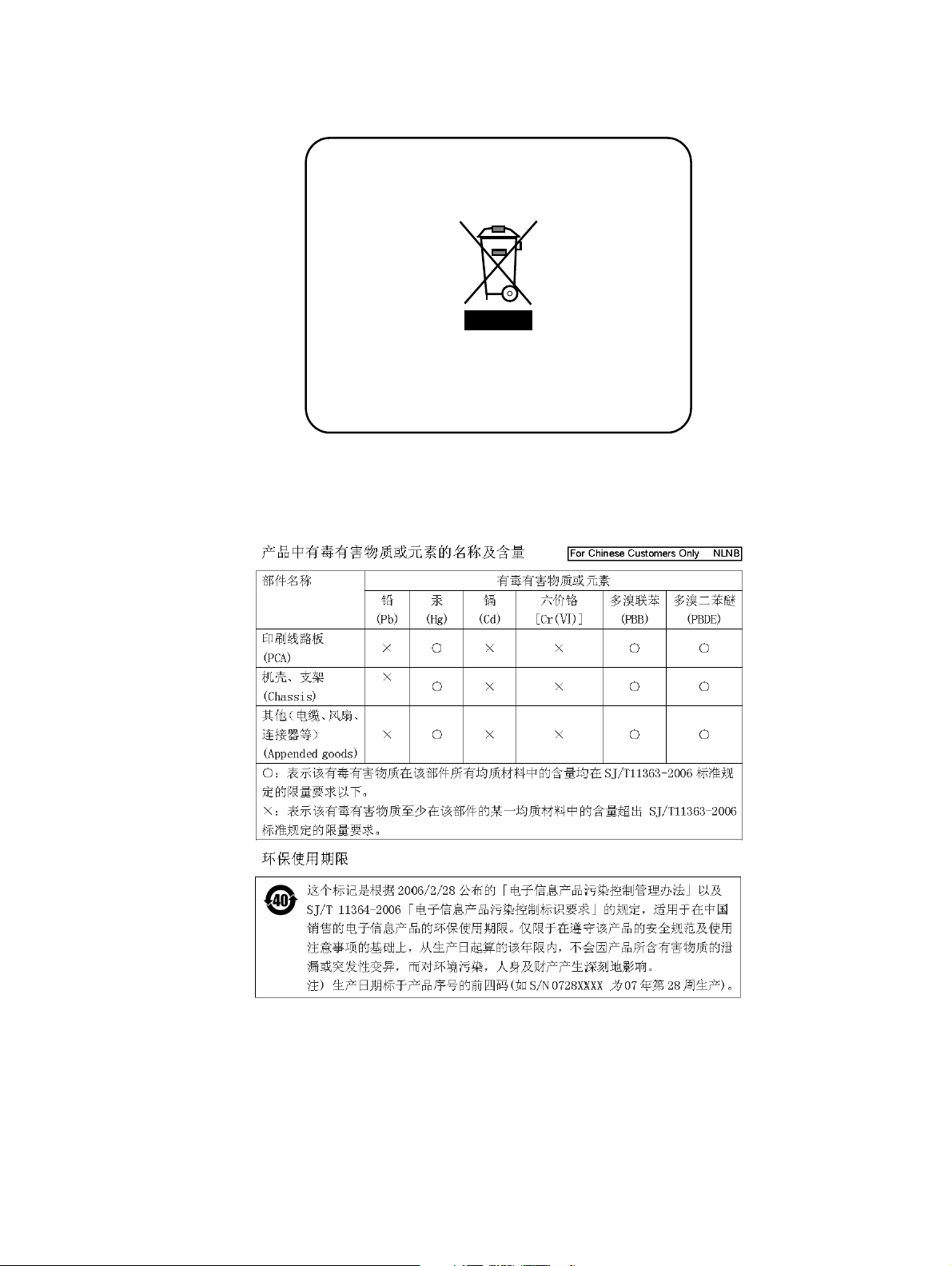
European Parliament and Council Directive 2002/96/EC
Equipment Marked with the crossed-out Wheelie
Bin symbol complies with the European
Parliament and Council Directive 2002/96/EC (the
“WEEE Directive”) in the European Union.
For Products placed on the EU market after
August 13, 2005, please contact your local Anritsu
representative at the end of the product’s useful
life to arrange disposal in accordance with your
initial contract and the local law.
Chinese RoHS Compliance Statement
Page 6

Page 7
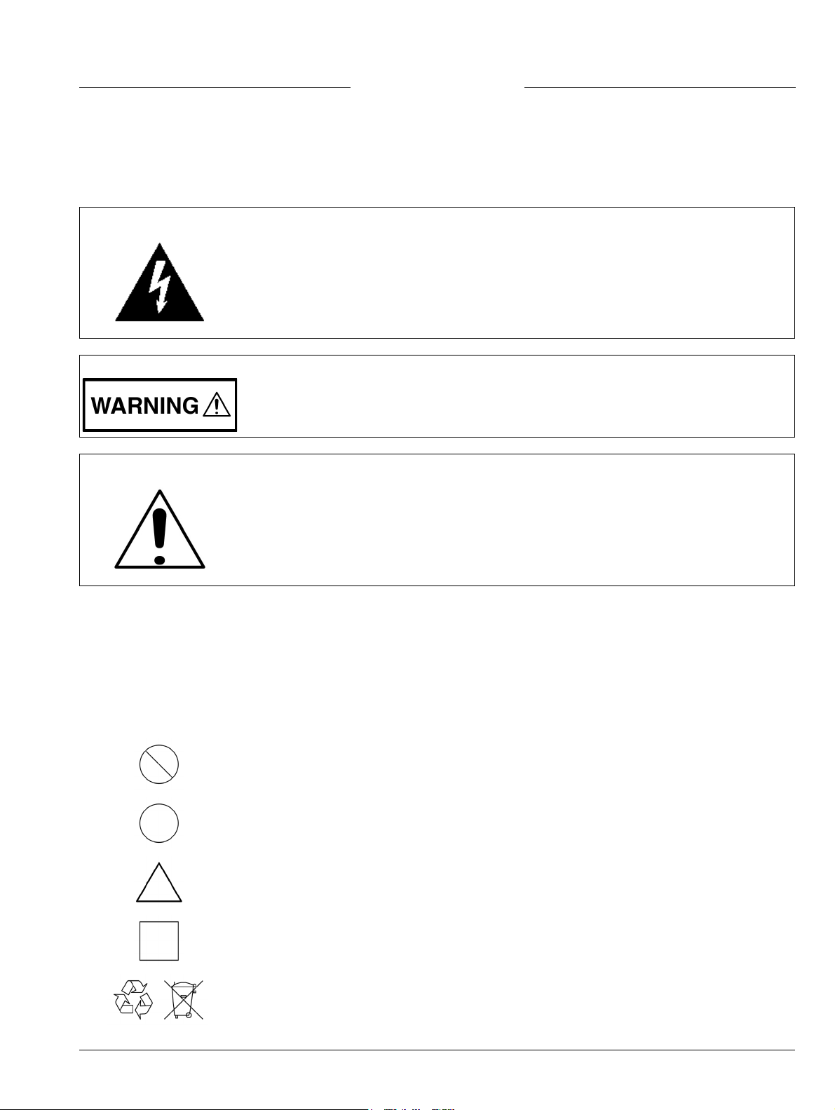
Safety Symbols
To prevent the risk of personal injury or loss related to equipment malfunction, Anritsu Company uses the
following symbols to indicate safety-related information. For your own safety, please read the information
carefully before operating the equipment.
Symbols Used in Manuals
Danger
This indicates a risk from a very dangerous condition or procedure that could result in
serious injury or death and possible loss related to equipment malfunction. Follow all
precautions and procedures to minimize this risk.
Warning
Caution
This indicates a risk from a hazardous condition or procedure that could result in
light-to-severe injury or loss related to equipment malfunction. Follow all precautions
and procedures to minimize this risk.
This indicates a risk from a hazardous procedure that could result in loss related to
equipment malfunction. Follow all precautions and procedures to minimize this risk.
Safety Symbols Used on Equipment and in Manuals
The following safety symbols are used inside or on the equipment near operation locations to provide
information about safety items and operation precautions. Ensure that you clearly understand the meanings of
the symbols and take the necessary precautions before operating the equipment. Some or all of the following
five symbols may or may not be used on all Anritsu equipment. In addition, there may be other labels attached
to products that are not shown in the diagrams in this manual.
This indicates a prohibited operation. The prohibited operation is indicated symbolically
in or near the barred circle.
This indicates a compulsory safety precaution. The required operation is indicated
symbolically in or near the circle.
This indicates a warning or caution. The contents are indicated symbolically in or near
the triangle.
This indicates a note. The contents are described in the box.
These indicate that the marked part should be recycled.
ML2419A OMM PN: 10585-00007 Rev. B Safety-1
Page 8
For Safety
Warning
Warning
Warning
Always refer to the operation manual when working near locations at which
the alert mark, shown on the left, is attached. If the operation, etc., is
performed without heeding the advice in the operation manual, there is a
risk of personal injury. In addition, the equipment performance may be
reduced.
Moreover, this alert mark is sometimes used with other marks and
descriptions indicating other dangers.
When supplying power to this equipment, connect the accessory 3-pin
power cord to a 3-pin grounded power outlet. If a grounded 3-pin outlet is
not available, use a conversion adapter and ground the green wire, or
connect the frame ground on the rear panel of the equipment to ground. If
power is supplied without grounding the equipment, there is a risk of
receiving a severe or fatal electric shock.
This equipment can not be repaired by the operator. Do not attempt to
remove the equipment covers or to disassemble internal components.
Only qualified service technicians with a knowledge of electrical fire and
shock hazards should service this equipment. There are high-voltage parts
in this equipment presenting a risk of severe injury or fatal electric shock to
untrained personnel. In addition, there is a risk of damage to precision
components.
Electrostatic Discharge (ESD) can damage the highly sensitive circuits in
the instrument. ESD is most likely to occur as test devices are being
Caution
Safety-2 PN: 10585-00007 Rev. B ML2419A OMM
connected to, or disconnected from, the instrument’s front and rear panel
ports and connectors. You can protect the instrument and test devices by
wearing a static-discharge wristband. Alternatively, you can ground
yourself to discharge any static charge by touching the outer chassis of the
grounded instrument before touching the instrument’s front and rear panel
ports and connectors. Avoid touching the test port center conductors
unless you are properly grounded and have eliminated the possibility of
static discharge.
Repair of damage that is found to be caused by electrostatic discharge is
not covered under warranty.
Page 9

Table of Contents
Chapter 1—General Information
1-1 Scope of Manual. . . . . . . . . . . . . . . . . . . . . . . . . . . . . . . . . . . . . . . . . . . . . . . . . . . . . . . . . . . . 1-1
1-2 Introduction . . . . . . . . . . . . . . . . . . . . . . . . . . . . . . . . . . . . . . . . . . . . . . . . . . . . . . . . . . . . . . . . 1-1
1-3 Identification . . . . . . . . . . . . . . . . . . . . . . . . . . . . . . . . . . . . . . . . . . . . . . . . . . . . . . . . . . . . . . . 1-1
1-4 Options and Accessories . . . . . . . . . . . . . . . . . . . . . . . . . . . . . . . . . . . . . . . . . . . . . . . . . . . . . 1-1
1-5 Verification and Test . . . . . . . . . . . . . . . . . . . . . . . . . . . . . . . . . . . . . . . . . . . . . . . . . . . . . . . . . 1-2
Instrument Control . . . . . . . . . . . . . . . . . . . . . . . . . . . . . . . . . . . . . . . . . . . . . . . . . . . . . . . . 1-2
Test Conditions . . . . . . . . . . . . . . . . . . . . . . . . . . . . . . . . . . . . . . . . . . . . . . . . . . . . . . . . . . 1-2
1-6 Related Documentation . . . . . . . . . . . . . . . . . . . . . . . . . . . . . . . . . . . . . . . . . . . . . . . . . . . . . . 1-2
Chapter 2—Installation
2-1 Introduction . . . . . . . . . . . . . . . . . . . . . . . . . . . . . . . . . . . . . . . . . . . . . . . . . . . . . . . . . . . . . . . . 2-1
2-2 Initial Inspection . . . . . . . . . . . . . . . . . . . . . . . . . . . . . . . . . . . . . . . . . . . . . . . . . . . . . . . . . . . . 2-1
2-3 Power Requirements . . . . . . . . . . . . . . . . . . . . . . . . . . . . . . . . . . . . . . . . . . . . . . . . . . . . . . . . 2-1
AC Line Power. . . . . . . . . . . . . . . . . . . . . . . . . . . . . . . . . . . . . . . . . . . . . . . . . . . . . . . . . . . 2-1
Fuses. . . . . . . . . . . . . . . . . . . . . . . . . . . . . . . . . . . . . . . . . . . . . . . . . . . . . . . . . . . . . . . . . . 2-1
Grounding . . . . . . . . . . . . . . . . . . . . . . . . . . . . . . . . . . . . . . . . . . . . . . . . . . . . . . . . . . . . . . 2-1
2-4 Environmental. . . . . . . . . . . . . . . . . . . . . . . . . . . . . . . . . . . . . . . . . . . . . . . . . . . . . . . . . . . . . . 2-1
2-5 Rack Mounting . . . . . . . . . . . . . . . . . . . . . . . . . . . . . . . . . . . . . . . . . . . . . . . . . . . . . . . . . . . . . 2-2
2-6 Storage and Shipment . . . . . . . . . . . . . . . . . . . . . . . . . . . . . . . . . . . . . . . . . . . . . . . . . . . . . . . 2-2
Preparation for Storage . . . . . . . . . . . . . . . . . . . . . . . . . . . . . . . . . . . . . . . . . . . . . . . . . . . . 2-2
Environmental Requirements . . . . . . . . . . . . . . . . . . . . . . . . . . . . . . . . . . . . . . . . . . . . . . . 2-2
Preparation for Shipment. . . . . . . . . . . . . . . . . . . . . . . . . . . . . . . . . . . . . . . . . . . . . . . . . . . 2-2
Chapter 3—Connections
3-1 Introduction . . . . . . . . . . . . . . . . . . . . . . . . . . . . . . . . . . . . . . . . . . . . . . . . . . . . . . . . . . . . . . . . 3-1
3-2 Front Panel . . . . . . . . . . . . . . . . . . . . . . . . . . . . . . . . . . . . . . . . . . . . . . . . . . . . . . . . . . . . . . . . 3-1
3-3 Rear Panel . . . . . . . . . . . . . . . . . . . . . . . . . . . . . . . . . . . . . . . . . . . . . . . . . . . . . . . . . . . . . . . . 3-2
Chapter 4—Operation with an ML2430A Series Power Meter
4-1 Performing a Verification . . . . . . . . . . . . . . . . . . . . . . . . . . . . . . . . . . . . . . . . . . . . . . . . . . . . . 4-1
4-2 RF Calibrator . . . . . . . . . . . . . . . . . . . . . . . . . . . . . . . . . . . . . . . . . . . . . . . . . . . . . . . . . . . . . . 4-4
4-3 Interpreting the Results. . . . . . . . . . . . . . . . . . . . . . . . . . . . . . . . . . . . . . . . . . . . . . . . . . . . . . . 4-4
dB Error Figure . . . . . . . . . . . . . . . . . . . . . . . . . . . . . . . . . . . . . . . . . . . . . . . . . . . . . . . . . . 4-4
Pass/Fail Criteria . . . . . . . . . . . . . . . . . . . . . . . . . . . . . . . . . . . . . . . . . . . . . . . . . . . . . . . . . 4-5
Absolute Error . . . . . . . . . . . . . . . . . . . . . . . . . . . . . . . . . . . . . . . . . . . . . . . . . . . . . . . . . . . 4-5
Linearity . . . . . . . . . . . . . . . . . . . . . . . . . . . . . . . . . . . . . . . . . . . . . . . . . . . . . . . . . . . . . . . . 4-5
Range Change Error . . . . . . . . . . . . . . . . . . . . . . . . . . . . . . . . . . . . . . . . . . . . . . . . . . . . . . 4-5
4-4 Diagnostic Mode . . . . . . . . . . . . . . . . . . . . . . . . . . . . . . . . . . . . . . . . . . . . . . . . . . . . . . . . . . . . 4-6
ML2419A OMM PN: 10585-00007 Rev. B Contents-1
Page 10

Table of Contents (Continued)
Chapter 5—Operation with an ML248xx or ML249xA Series Power Meter
5-1 Performing a Verification. . . . . . . . . . . . . . . . . . . . . . . . . . . . . . . . . . . . . . . . . . . . . . . . . . . . . . 5-1
5-2 Interpreting the Results. . . . . . . . . . . . . . . . . . . . . . . . . . . . . . . . . . . . . . . . . . . . . . . . . . . . . . . 5-2
dB Error Figure . . . . . . . . . . . . . . . . . . . . . . . . . . . . . . . . . . . . . . . . . . . . . . . . . . . . . . . . . . 5-2
Pass/Fail Criteria . . . . . . . . . . . . . . . . . . . . . . . . . . . . . . . . . . . . . . . . . . . . . . . . . . . . . . . . . 5-3
Absolute Error . . . . . . . . . . . . . . . . . . . . . . . . . . . . . . . . . . . . . . . . . . . . . . . . . . . . . . . . . . . 5-3
Linearity . . . . . . . . . . . . . . . . . . . . . . . . . . . . . . . . . . . . . . . . . . . . . . . . . . . . . . . . . . . . . . . . 5-3
Range Change Error . . . . . . . . . . . . . . . . . . . . . . . . . . . . . . . . . . . . . . . . . . . . . . . . . . . . . . 5-3
5-3 Using the Diagnostics Menu . . . . . . . . . . . . . . . . . . . . . . . . . . . . . . . . . . . . . . . . . . . . . . . . . . . 5-4
5-4 Using the Range Calibrator Config Menu . . . . . . . . . . . . . . . . . . . . . . . . . . . . . . . . . . . . . . . . . 5-4
Chapter 6—Maintenance
6-1 Introduction . . . . . . . . . . . . . . . . . . . . . . . . . . . . . . . . . . . . . . . . . . . . . . . . . . . . . . . . . . . . . . . . 6-1
6-2 Recommended Test Equipment . . . . . . . . . . . . . . . . . . . . . . . . . . . . . . . . . . . . . . . . . . . . . . . . 6-1
6-3 Test Conditions . . . . . . . . . . . . . . . . . . . . . . . . . . . . . . . . . . . . . . . . . . . . . . . . . . . . . . . . . . . . . 6-1
6-4 Test Setup . . . . . . . . . . . . . . . . . . . . . . . . . . . . . . . . . . . . . . . . . . . . . . . . . . . . . . . . . . . . . . . . 6-2
6-5 Power Supply Tests . . . . . . . . . . . . . . . . . . . . . . . . . . . . . . . . . . . . . . . . . . . . . . . . . . . . . . . . . 6-2
+12 V Supply Test . . . . . . . . . . . . . . . . . . . . . . . . . . . . . . . . . . . . . . . . . . . . . . . . . . . . . . . . 6-2
–12 V Supply Test . . . . . . . . . . . . . . . . . . . . . . . . . . . . . . . . . . . . . . . . . . . . . . . . . . . . . . . . 6-2
+5 V Supply Test . . . . . . . . . . . . . . . . . . . . . . . . . . . . . . . . . . . . . . . . . . . . . . . . . . . . . . . . . 6-2
50 MHz Supply . . . . . . . . . . . . . . . . . . . . . . . . . . . . . . . . . . . . . . . . . . . . . . . . . . . . . . . . . . 6-2
6-6 Reference Levels . . . . . . . . . . . . . . . . . . . . . . . . . . . . . . . . . . . . . . . . . . . . . . . . . . . . . . . . . . . 6-5
High Level Offsets . . . . . . . . . . . . . . . . . . . . . . . . . . . . . . . . . . . . . . . . . . . . . . . . . . . . . . . . 6-5
Positive High Level . . . . . . . . . . . . . . . . . . . . . . . . . . . . . . . . . . . . . . . . . . . . . . . . . . . . . . . 6-5
Balancing VH+ and VH– . . . . . . . . . . . . . . . . . . . . . . . . . . . . . . . . . . . . . . . . . . . . . . . . . . . 6-5
Positive Low Level . . . . . . . . . . . . . . . . . . . . . . . . . . . . . . . . . . . . . . . . . . . . . . . . . . . . . . . . 6-6
Low Level Differential Voltage . . . . . . . . . . . . . . . . . . . . . . . . . . . . . . . . . . . . . . . . . . . . . . . 6-6
6-7 Microcontroller Operation . . . . . . . . . . . . . . . . . . . . . . . . . . . . . . . . . . . . . . . . . . . . . . . . . . . . . 6-6
6-8 Attenuator Function. . . . . . . . . . . . . . . . . . . . . . . . . . . . . . . . . . . . . . . . . . . . . . . . . . . . . . . . . . 6-7
6-9 Reference Zero Function . . . . . . . . . . . . . . . . . . . . . . . . . . . . . . . . . . . . . . . . . . . . . . . . . . . . . 6-7
6-10 Low Level Attenuators . . . . . . . . . . . . . . . . . . . . . . . . . . . . . . . . . . . . . . . . . . . . . . . . . . . . . . . 6-8
6-11 High Level Attenuators . . . . . . . . . . . . . . . . . . . . . . . . . . . . . . . . . . . . . . . . . . . . . . . . . . . . . . . 6-9
6-12 Rear Panel Functions . . . . . . . . . . . . . . . . . . . . . . . . . . . . . . . . . . . . . . . . . . . . . . . . . . . . . . . . 6-9
5 V Reference Output . . . . . . . . . . . . . . . . . . . . . . . . . . . . . . . . . . . . . . . . . . . . . . . . . . . . . 6-9
Trigger Output . . . . . . . . . . . . . . . . . . . . . . . . . . . . . . . . . . . . . . . . . . . . . . . . . . . . . . . . . . 6-10
6-13 ML2419A 50 MHz, 0 dBm Reference Calibration Procedure . . . . . . . . . . . . . . . . . . . . . . . . . 6-10
Scope. . . . . . . . . . . . . . . . . . . . . . . . . . . . . . . . . . . . . . . . . . . . . . . . . . . . . . . . . . . . . . . . . 6-10
Equipment Required . . . . . . . . . . . . . . . . . . . . . . . . . . . . . . . . . . . . . . . . . . . . . . . . . . . . . 6-10
Frequency Calibration for the 50 MHz, 0 dBm Reference . . . . . . . . . . . . . . . . . . . . . . . . . 6-11
Procedure . . . . . . . . . . . . . . . . . . . . . . . . . . . . . . . . . . . . . . . . . . . . . . . . . . . . . . . . . . . . . 6-11
Output Power Level Calibration for the 50 MHz, 0 dBm Reference . . . . . . . . . . . . . . . . . 6-15
Procedure . . . . . . . . . . . . . . . . . . . . . . . . . . . . . . . . . . . . . . . . . . . . . . . . . . . . . . . . . . . . . 6-15
6-14 Post test . . . . . . . . . . . . . . . . . . . . . . . . . . . . . . . . . . . . . . . . . . . . . . . . . . . . . . . . . . . . . . . . . 6-21
Contents-2 PN: 10585-00007 Rev. B ML2419A OMM
Page 11

Appendix A—ML2419A Range Calibrator Specifications
Appendix B—Range Calibrator Verification Spreadsheet Information
B-1 Introduction . . . . . . . . . . . . . . . . . . . . . . . . . . . . . . . . . . . . . . . . . . . . . . . . . . . . . . . . . . . . . . . . B-1
B-2 Using the Spreadsheet Form . . . . . . . . . . . . . . . . . . . . . . . . . . . . . . . . . . . . . . . . . . . . . . . . . . B-1
ML2419A OMM PN: 10585-00007 Rev. B Contents-3
Page 12

Contents-4 PN: 10585-00007 Rev. B ML2419A OMM
Page 13
Chapter 1 — General Information
A
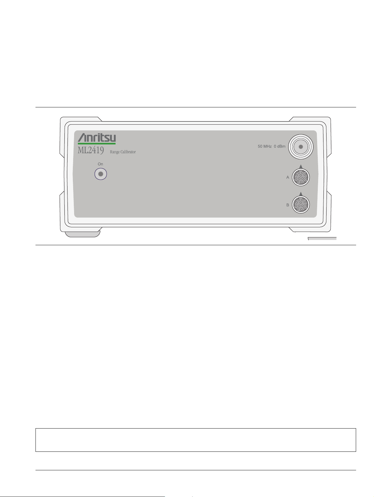
1-1 Scope of Manual
This manual provides installation, operation, and maintenance information for the Anritsu model ML2419A
Range Calibrator.
Figure 1-1. ML2419A Range Calibrator
1-2 Introduction
This chapter provides information to familiarize the user with the basic ML2419A Range Calibrator. Included
is information about the equipment identification number, options, and accessories.
1-3 Identification
The ML2419A identification number is affixed to the rear panel (see Figure 3-2, “ML2419A Rear Panel”
on page 3-2). Please use the complete identification number when ordering parts or corresponding with the
Anritsu Customer Service department.
1-4 Options and Accessories
The ML2419A Range Calibrator is available with the following options:
• 760-209: Hard Side Transit Case
• D41310: Soft Sided Carry Case with shoulder strap
• 2400-82: Rack Mount, single unit
• 2400-83: Rack Mount, side-by-side
Note
ML2419A OMM PN: 10585-00007 Rev. B 1-1
Options 2400-82 and 2400-83 are mutually exclusive.
1.5 meter sensor cables are supplied with the Anritsu ML24xxx Series Power Meter.
Page 14

1-5 Verification and Test Chapter 1 — General Information
1-5 Verification and Test
The ML2419A Range Calibrator provides a traceable series of voltages to facilitate accuracy measurements for
the ML2430A and ML248xx / ML249xA Series Power Meter signal channels. The voltages are produced by
means of a precision voltage reference and a series of switchable attenuators, operated by a microcontroller. All
voltages produced are accurate, stable, and low-noise such that errors inherent in the Range Calibrator itself
do not contribute significantly to the error measurements of the signal channel.
Instrument Control
The Range Calibrator is controlled remotely using the ML24xxx Series Power Meter menu system via the
sensor cables. On connection of a sensor cable, the meter automatically senses the presence of the Range
Calibrator. From this point, the Range Calibrator is controlled using the ML24xxx keypad and displayed
menus.
Test Conditions
The Range Calibrator is intended for use as a calibration instrument, and as such must be operated under
controlled conditions of temperature and humidity in order to meet its specified precision and stability.
All tests must be performed at 25 °C ± 10 °C (77 °F ± 18 °F) and a relative humidity of less than 75 % at 40 °C
(104 °F), non-condensing.
Prior to making any precision measurements, allow the Range Calibrator and the Power Meter to warm up for
a period of 15 minutes from power on. If the power supply is interrupted for any reason, allow a similar settling
period.
1-6 Related Documentation
The procedures in this manual may require reference to the following Power Meter Operation and Remote
Programming manuals and other information provided on the product disc:
• ML2430A Series Operation and Remote Programming Manual: 10585-00001
• ML248xx / ML249xA Operation Manual: 13000-00238
• ML248xx / ML249xA Remote Programming Manual: 13000-00239
• Anritsu Power Meters and Sensors Application and Documentation Disc: 2300-283
The above product disc contains all of the required documentation and spreadsheets specified in this manual.
Updated information can be downloaded from each product page on the Anritsu web site:
http://www.anritsu.com
1-2 PN: 10585-00007 Rev. B ML2419A OMM
Page 15

Chapter 2 — Installation
2-1 Introduction
This section provides information for the initial inspection and preparation for use of the ML2419A Range
Calibrator. Shipping and storage information is also included.
2-2 Initial Inspection
Inspect the shipping container for damage. If the container or cushioning material is damaged, retain until the
contents of the shipment have been checked against the packing list and the instrument has been checked for
mechanical and electrical operation.
If the instrument is damaged mechanically, notify your local sales representative or Anritsu Customer Service
Center. If either the shipping container is damaged or the cushioning material shows signs of stress, notify the
carrier as well as Anritsu. Retain the shipping materials for the carrier's inspection.
2-3 Power Requirements
The ML2419A Range Calibrator is operated from AC line power and is intended as an Installation
(Overvoltage) Category II, Insulation Category I device. A front-panel LED indicates when power is applied.
AC Line Power
The ML2419A Range Calibrator can operate on AC input power of 90 to 132 V or 180 to 264V, 47 Hz to 63 Hz,
6 VA max.
Fuses
The ML2419A Range Calibrator AC input line is protected by an internally mounted fuse. This fuse should
only be changed by qualified service personnel. Replace only with a fuse of the same type and rating:
0.5 A, 250 V, antisurge (T).
Grounding
The ML2419A Range Calibrator must be properly grounded. Failure to ground the instrument could be
hazardous to operating personnel. The instrument is supplied with a three-conductor power cord. The
instrument is properly grounded during AC line operation when the plug is connected to a properly installed
three-prong receptacle. A grounding terminal is also provided on the rear panel.
2-4 Environmental
The ML2419A Range Calibrator is designed to operate within the temperature range of 0 °C to 50 °C
(32 °F to 122 °F) with a maximum relative humidity of 95 % at 40 °C (104 °F), non-condensing.
Full accuracy is specified at 25 °C ± 10 °C (77 °F ± 18 °F), at a maximum relative humidity of 75 % at 40 °C
(104 °F), non-condensing.
ML2419A OMM PN: 10585-00007 Rev. B 2-1
Page 16

2-5 Rack Mounting Chapter 2 — Installation
2-5 Rack Mounting
The ML2419A Range Calibrator can be ordered with rack mounting hardware that allows the unit to be
mounted into a standard 19 inch equipment rack. There are two rack mount option kits available:
• The 2400-82 Rack Mount option allows the installation of a single ML2419A in either the left or
right-side rack position.
• The 2400-83 Rack Mount option allows mounting of two ML2419A Range Calibrators (or one Range
Calibrator and one ML24xxx Series Power Meter) side-by-side.
The instrument itself must be ordered from the factory as a rack mount unit. As such, it will be fitted with rack
mount top and bottom cases that have extra mounting holes so that the rack mount kits can be installed.
Instructions for installing the rack mount kits are supplied with the rack mounting kits.
2-6 Storage and Shipment
The following paragraphs describe preparing the range calibrator for storage and shipment.
Preparation for Storage
Preparing the range calibrator for storage consists of cleaning the unit and packing it with moisture-absorbing
desiccant crystals.
Environmental Requirements
Store the unit in a temperature controlled environment that is maintained between –40 and +70 °C
(–40 to +156 °F), with a maximum humidity of 95 % at 40 °C (104 °F), non-condensing.
Preparation for Shipment
To provide maximum protection against damage in transit, the range calibrator should be repackaged in the
original shipping container. If this container is no longer available and the range calibrator is being returned to
Anritsu for repair, follow the packaging instructions below:
• Use a Suitable Container: Obtain a corrugated cardboard carton with a 275 pound test strength. This
carton should have inside dimensions of no less than six inches larger than the instrument dimensions to
allow for cushioning.
• Protect the Instrument: Wrap the instrument to protect the finish.
• Cushion the Instrument: Cushion the instrument on all sides by tightly packing dunnage or urethane
foam between the carton and the instrument. Provide at least three inches of dunnage on all sides.
• Seal the Container: Seal the carton using either shipping tape or an industrial stapler.
• Address the Container: If the instrument is being returned to Anritsu for service, mark the address of
the appropriate Anritsu service center (refer to
Authorization (RMA) number, and your return address on the carton in a prominent location.
http://www.anritsu.com/contact.asp), the Return Materials
2-2 PN: 10585-00007 Rev. B ML2419A OMM
Page 17
Chapter 3 — Connections
A
3-1 Introduction
This section provides descriptions of the ML2419A Range Calibrator front and rear panels and connectors.
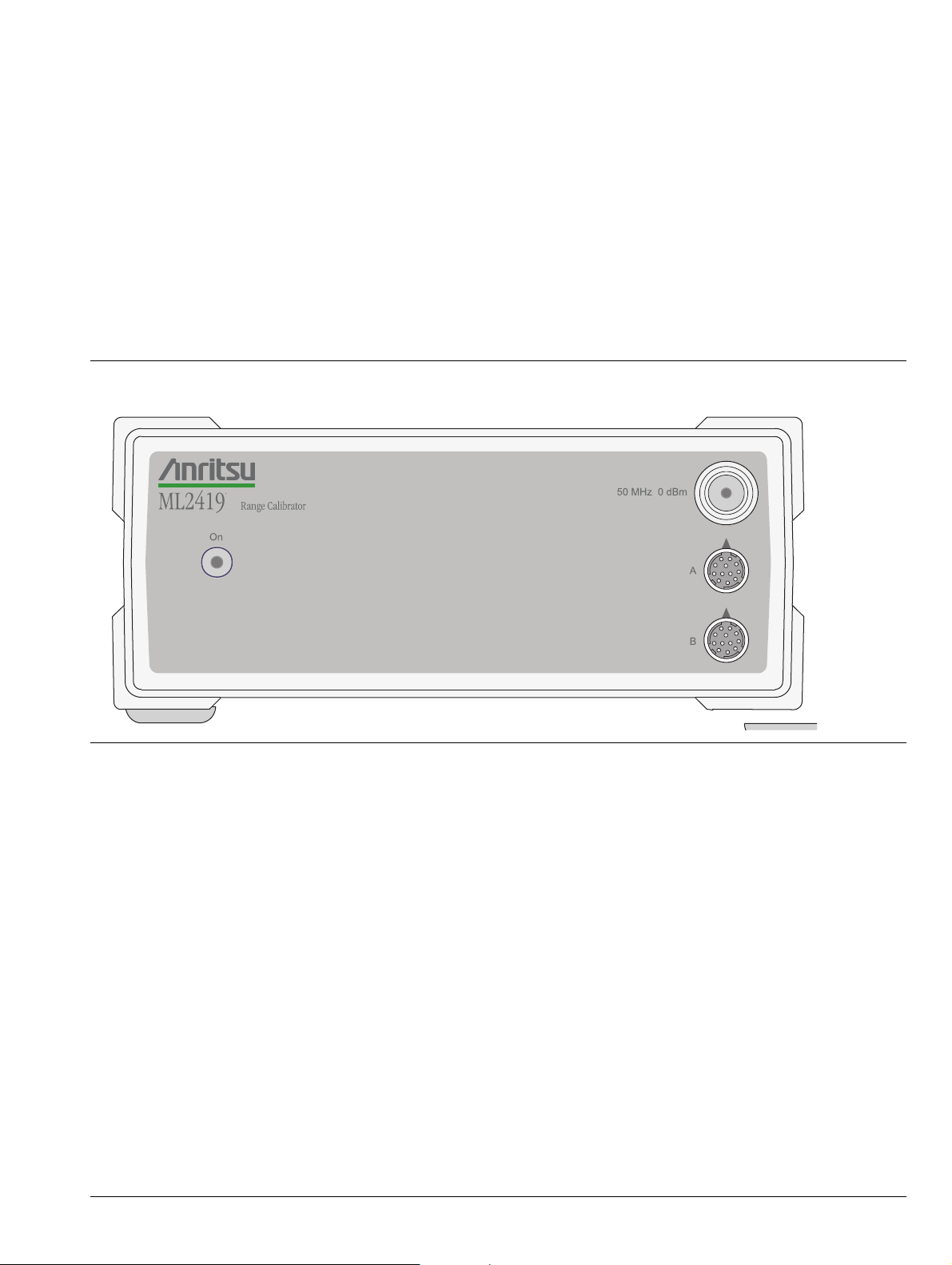
3-2 Front Panel
The front panel is illustrated in Figure 3-1. There are three connectors and an ON/OFF indicator LED on the
front panel.
Figure 3-1. ML2419A Front Panel
AC Power LED: This LED lights whenever AC power is applied to the ML2419A Range Calibrator and the
power switch is in the on position.
50 MHz 0 dBm Connector: This precision output provides a nominal 50 MHz, 0.0 dBm reference signal to
approximate the sensor calibration. For a traceable calibration, use the 50 MHz source on the ML24xxx Series
Power Meter. The 0.0 dBm level is available at this N-type connector whenever the Range Calibrator is
powered on.
Sensor A Connector: This connector is a 12 pin, circular precision connector to be used in conjunction with
1.5 meter power sensor cables.
Sensor B Connector: This connector is a 12 pin, circular precision connector to be used in conjunction with
1.5 meter power sensor cables.
ML2419A OMM PN: 10585-00007 Rev. B 3-1
Page 18

3-3 Rear Panel Chapter 3 — Connections
3-3 Rear Panel
The Rear Panel has four connectors, the AC input voltage selector, and an ID number label.
Figure 3-2. ML2419A Rear Panel
AC Line Power Connector: The ML2419A Range Calibrator can operate on AC input power of 90 to 132 V or
180 to 264V, 47 Hz to 63 Hz, 50 VA max. The Range Calibrator must be properly configured using the voltage
selector for the voltage being applied. No on/off switch is provided, as the unit is powered continuously during
use. A front-panel LED indicates when power is applied.
Output 1 5V Reference: This function is reserved for future use.
Output 2 Trigger: This function is reserved for future use.
Chassis Ground: This grounding terminal can be used to connect the chassis ground of the Range Calibrator
to other equipment as necessary.
The instrument itself is properly grounded when the AC line plug is connected to a properly installed
three-prong receptacle.
ID Number Label: The ML2419A identification number is affixed to the rear panel. Please use the complete
identification number when ordering parts or corresponding with the Anritsu Customer Service department.
3-2 PN: 10585-00007 Rev. B ML2419A OMM
Page 19

Chapter 4 — Operation with an ML2430A
-erom-A
Range Calibrator
ANRITSU
A
B
A and B - more -
Range Calibrator
ANRITSU
Series Power Meter
4-1 Performing a Verification
The performance of the Anritsu ML2430A Series Power Meter’s individual signal channel inputs are verified
using the following procedure. References in this procedure to sensor input B apply to model ML2438A
(dual-channel) power meter only. Before starting this procedure, refer to Section 1-5 “Verification and Test” for
information on the appropriate Test Conditions.
1. Connect the Range Calibrator to the Power Meter using 1.5 meter sensor cables. The inputs to be verified
must be connected to the corresponding connectors on the Range Calibrator; that is, connect Power
Meter connector A to Range Calibrator connector A, and connector B to connector B (ML2438A only).
2. On connection of the sensor cables, the meter automatically detects that a Range Calibrator is present
and displays the performance verification menus.
Figure 4-1. ML2419A Range Calibrator Top Menu (single-channel power meter)
Figure 4-2. ML2419A Range Calibrator Top Menu (dual-channel power meter)
3. The performance verification tests will begin when the soft key for the sensor input to be verified is
selected. For single-channel power meters (ML2437A), press the A soft key. For dual-channel models
(ML2438A), press A, B, or A and B. If the “A and B” soft key is selected, all measurements are first taken
on sensor input A, then repeated for sensor input B. Performance verification tests for each sensor input
are performed in the following sequence:
• The signal channel input is zeroed.
• The Power Meter signal channels are checked at the upper and lower levels of each measurement
range. A null is performed at each range setting prior to every measurement.
ML2419A OMM PN: 10585-00007 Rev. B 4-1
Page 20

4-1 Performing a Verification Chapter 4 — Operation with an ML2430A Series Power Meter
SENSOR
Range calibrator results SensorA
Range (upper) Range (lower)
1 6.996
2 -11.822
3 -25.864
4 -41.806
5 -57.805
1 -11.822
2 -25.771
3 -41.808
4 -57.814
5 -61.727
PRINT REPEAT - exit -
4. When all measurements have been performed on the selected inputs, the results are presented on the
screen and the following soft keys are displayed:
Figure 4-3. ML2419A Range Calibrator Verification Results Menu Example
SENSOR: Toggles the display to show the data for each sensor channel verified. If only one channel has been
verified, the SENSOR soft key shown in Figure 4-3 will not be displayed.
PRINT: The verification data can be printed using the PRINT selection. The data is output through the
ML2430A Series Power Meter rear panel printer port. The printer type will be the same as that selected when
operating the meter in stand-alone mode. Refer to the ML2430A Series Power Meter Operation Manual for
information on print commands and supported printers.
See Figure 4-4 for an example of a printed Range Calibrator Report.
The results of the Range Calibrator tests are available from the power meter via the GPIB, once the
Note
Range Calibrator is disconnected from the power meter. Refer to the description of the RCD
command in the ML2430A Series Power Meter Operation Manual.
REPEAT: The last selected performance verification sequence is repeated.
-exit-: Returns the user to the top-level menu (Figure 4-1 or Figure 4-2).
5. To exit the Range Calibrator mode, disconnect the sensor cables. The Power Meter will reset to the
default mode.
4-2 PN: 10585-00007 Rev. B ML2419A OMM
Page 21

Chapter 4 — Operation with an ML2430A Series Power Meter 4-1 Performing a Verification
Figure 4-4. Example Range Calibrator Report
ML2419A OMM PN: 10585-00007 Rev. B 4-3
Page 22

4-2 RF Calibrator Chapter 4 — Operation with an ML2430A Series Power Meter
4-2 RF Calibrator
The Range Calibrator RF Calibrator output can be used to approximate the 0.0 dBm at 50 MHz reference
calibration of a sensor. Calibration is accomplished using the ML2430A Series Power Meter Cal/Zero menu.
Sensors should be zeroed before being calibrated (refer to the ML2430A Series Power Meter Operation Manual,
part number 10585-00001). Zeroing a power sensor compensates for noise and thermal EMF of the device
under test, and is recommended prior to taking important power readings in the bottom 20 dB of a power
sensor’s dynamic range.
When the sensor is first attached, the message SENSOR x ZERO not done (where x = A or B as appropriate) is
displayed. Perform the sensor zeroing procedure described in the ML2430A Series Power Meter Operation
Manual.
After zeroing the power sensor, perform the following procedure to calibrate the sensor:
1. Connect the sensor to the ML2419A Range Calibrator 50 MHz, 0.0 dBm reference output connector
labeled CALIBRATOR.
2. Press the Cal/Zero front panel key and the Cal 0 dBm soft key, then select the appropriate sensor. Note
that if only one sensor is connected, the A and B selection is not displayed and the calibration process
begins immediately.
3. On successful completion of the calibration operation, the buzzer sounds.
The sensors can also be calibrated using the GPIB CAL command (refer to the programming section of the
ML2430A Series Power Meter Operation Manual).
4-3 Interpreting the Results
The tabular data presented consist of the values read by the meter for each range, with one measurement
taken at each end of each range. For each of these measurements, there is an expected value. These measured
values must meet the specification limits defined in Appendix A, “ML2419A Range Calibrator Specifications”.
dB Error Figure
The Range Calibrator measures the “Zero” level, and the “Upper” and “Lower” limits of each of the five ranges
(both channels on a dual-channel meter). To calculate the dB Error Figure for each level, subtract the expected
level from the measured level.
4-4 PN: 10585-00007 Rev. B ML2419A OMM
Page 23

Chapter 4 — Operation with an ML2430A Series Power Meter 4-3 Interpreting the Results
Pass/Fail Criteria
The meter should be accepted as PASSED if it meets the following conditions applied to the error figures
calculated by the above method.
Note
Table 4 - 1 . Pass / Fail Criteria
Range Specifications (dB)
Range 1 Absolute Error –0.028 ≤ R1U ≤ 0.028
Range 1 Linearity –0.028 ≤ R1U – R1L ≤ 0.028
Ranges 1 – 2 Change –0.028 ≤ R1L – R2U ≤ 0.028
Range 2 Linearity –0.028 ≤ R2U – R2L ≤ 0.028
Ranges 2 – 3 Change –0.028 ≤ R2L – R3U ≤ 0.028
Range 3 Absolute Error –0.028 ≤ R3U ≤ 0.028
Range 3 Linearity –0.028 ≤ R3U – R3L ≤ 0.028
Ranges 3 – 4 Change –0.028 ≤ R3L – R4U ≤ 0.028
Range 4 Linearity –0.028 ≤ R4U – R4L ≤ 0.028
Range 4 – 5 Change –0.075 ≤ R4L – R5U ≤ 0.075
Range 5 Linearity –0.023 ≤ R5U – R5L ≤ 0.023
Note that the provided Excel™ spreadsheet form can also be used to determine pass/fail status.
Refer to Appendix B, “Range Calibrator Verification Spreadsheet Information”.
Absolute Error
The calculated absolute error should be as shown in table above. For example, the calculated absolute errors
for Range 1 Upper (R1U) should be between –0.028 dB and +0.028 dB.
Linearity
The linearity values should be as shown in table above. For example, the Range 1 Lower (R1L) should differ
from Range 1 Upper (R1U) by no less than 0.028 dB.
Range Change Error
The range change error, defined as the difference between the errors for the two dB levels at the overlap
between any two ranges, should be as shown in the table above. For example, the maximum range change
error between Range 1 Lower and Range 2 Upper (R1L – R2U) should be between –0.028 dB and +0.028 dB.
ML2419A OMM PN: 10585-00007 Rev. B 4-5
Page 24

4-4 Diagnostic Mode Chapter 4 — Operation with an ML2430A Series Power Meter
6.990
Range Calibrator Diagnostics
Sensor A
Level Range 1 upper
SENSOR LEVEL ZERO - exit -
dB
4-4 Diagnostic Mode
The Diagnostics mode allows the user to investigate meter problems by holding on any of the fixed level
outputs to examine the results of a particular measurement. From the top-level menu press -more-and DIAGS.
When the Diagnostics option is selected, the SENSOR, LEVEL, and ZERO soft keys become available.
Figure 4-5. ML2419A Diagnostics Menu
SENSOR: Toggles the display to show the measurements for each channel. If only one channel is connected,
the SENSOR soft key shown in Figure 4-5 will not be displayed.
LEVEL: Selects the level to be verified.
ZERO: The selected sensor input is zeroed.
When a SENSOR and LEVEL are selected, the range calibrator outputs the required signal to the appropriate
sensor input on the meter, and the meter continuously measures it. The reading obtained for a particular
range should be the same as when the full set of tests were run (within the specifications listed in
Appendix A, “ML2419A Range Calibrator Specifications”). To obtain an accurate measurement, it is important
to ZERO at each selection of SENSOR and LEVEL.
-exit-: Returns the user to the top-level menu (Figure 4-1 or Figure 4-2).
4-6 PN: 10585-00007 Rev. B ML2419A OMM
Page 25

Chapter 5 — Operation with an ML248xx or ML249xA Series Power Meter
5-1 Performing a Verification
The performance of the ML248xx / ML249xA Series Power Meter’s individual signal channel inputs are
verified using the following procedure. References in this procedure to sensor input B apply to ML248xx and
ML2496A (dual-channel) power meters only. Before starting this procedure, refer to Section 1-5 “Verification
and Test” for information on the appropriate Test Conditions.
1. Connect the Range Calibrator to the Power Meter using 1.5 m sensor cables. The inputs to be verified
must be connected to the corresponding connectors on the Range Calibrator; that is, connect Power
Meter connector A to Range Calibrator connector A, and connector B to connector B (ML248xx and
ML2496A only).
2. On connection of the sensor cables, the power meter automatically detects the Range Calibrator and
displays the following screen.
Figure 5-1. ML2419A Range Calibrator Top Menu
3. Press the soft key of the sensor input to be verified. For single-channel power meters (ML2487x and
ML2495A), press the A soft key. For dual-channel models (ML248xx and ML2496A), press A, B, or
A&B. If the A & B soft key is selected, all measurements are first taken on sensor input A, then
repeated for sensor input B. Performance verification tests for each sensor input are performed in the
following sequence:
a. The signal channel input is zeroed.
b. The Power Meter signal channel are checked at the upper and lower levels of each measurement
range. A null is performed at each range setting prior to every measurement.
ML2419A OMM PN: 10585-00007 Rev. B 5-1
Page 26

5-2 Interpreting the Results Chapter 5 — Operation with an ML248xx or ML249xA Series Power Meter
4. When all measurements have been performed on the selected inputs, the results are presented on the
screen as shown below.
Figure 5-2. ML2419A Range Calibrator Verification Results Menu Example
The figure above shows the results for inputs A and B acquired by pressing the A & B soft key. Once results for
both inputs have been acquired, the information is retained until the power is turned off.
5-2 Interpreting the Results
The tabular data consists of the values read by the meter for each range, with one measurement taken at each
end of each range. For each of these measurements, the expected value must meet the specification limits as
defined in Appendix A, “ML2419A Range Calibrator Specifications”.
dB Error Figure
The Range Calibrator measures the "Zero" level, and the "Upper" and "Lower" limits of each of the five ranges
(both channels on a dual-channel meter). To calculate the dB Error Figure for each level, subtract the expected
level from the measured level.
5-2 PN: 10585-00007 Rev. B ML2419A OMM
Page 27

Chapter 5 — Operation with an ML248xx or ML249xA Series Power Meter 5-2 Interpreting the Results
Pass/Fail Criteria
The meter should be accepted as PASSED if it meets the error and linearity statistics in the following table.
Note
Table 5 - 1 . Pass / Fail Criteria
Range Specifications (dB)
Range 1 Absolute Error –0.020 ≤ R1U ≤ 0.020
Range 1 Linearity –0.040 ≤ R1U – R1L ≤ 0.040
Ranges 1 – 2 Change –0.030 ≤ R1L – R2U ≤ 0.030
Range 2 Linearity –0.040 ≤ R2U – R2L ≤ 0.040
Ranges 2 – 3 Change –0.030 ≤ R2L – R3U ≤ 0.030
Range 3 Absolute Error –0.020 ≤ R3U ≤ 0.020
Range 3 Linearity –0.040 ≤ R3U – R3L ≤ 0.040
Ranges 3 – 4 Change –0.030 ≤ R3L – R4U ≤ 0.030
Range 4 Linearity –0.040 ≤ R4U – R4L ≤ 0.040
Range 4 – 5 Change –0.030 ≤ R4L – R5U ≤ 0.030
Range 5 Linearity –0.040 ≤ R5U – R5L ≤ 0.040
Range 7 Absolute Error –0.030 ≤ R7U ≤ 0.030
Range 8 Absolute Error –0.030 ≤ R8U ≤ 0.030
Range 8 Linearity –0.085 ≤ R8U – R8L ≤ 0.085
Range 9 Absolute Error –0.050 ≤ R9U ≤ 0.050
Range 9 Linearity –0.18 ≤ R9U – R9L ≤ 0.18
Note that the provided Excel™ spreadsheet form can also be used to determine pass/fail status.
Refer to Appendix B, “Range Calibrator Verification Spreadsheet Information”.
Absolute Error
The calculated absolute error should be as shown in table above. For example, the calculated absolute errors
for Range 1 Upper (R1U) should be between –0.020 dB and +0.020 dB.
Linearity
The linearity values should be as shown in table above. For example, the Range 1 Lower (R1L) should differ
from Range 1 Upper (R1U) by no less than 0.040 dB.
Range Change Error
The range change error, defined as the difference between the errors for the two dB levels at the overlap
between any two ranges, should be as shown in the table above. For example, the maximum range change
error between Range 1 Lower and Range 2 Upper (R1L – R2U) should be between –0.030 dB and +0.030 dB.
ML2419A OMM PN: 10585-00007 Rev. B 5-3
Page 28

5-3 Using the Diagnostics Menu Chapter 5 — Operation with an ML248xx or ML249xA Series Power Meter
5-3 Using the Diagnostics Menu
The Diagnostics mode allows the user to investigate meter problems by holding on any of the fixed level
outputs to examine the results of a particular measurement.
1. Connect the Range Calibrator to the Power Meter using 1.5 m sensor cables. The inputs to be verified
must be connected to the corresponding connectors on the Range Calibrator; that is, connect Power
Meter connector A to Range Calibrator connector A, and connector B to connector B (ML248xx and
ML2496A only).
2. Press the Diag soft key to display the Rng Cal Diag group of commands and the Range Calibrator
Diagnostics dialog.
Figure 5-3. ML2419A Range Calibrator Diagnostics Menu
3. Press the Next Level soft key to display the required level. The range calibrator outputs the required
signal to the appropriate sensor input on the meter, and the meter continuously measures it. The
reading obtained for a particular range should be the same as when the full set of tests was run.
4. Press the Zero soft key to zero the residual range for the required level.
5. Press the Exit soft key to close the dialog and return to the main Range Cal menu.
5-4 Using the Range Calibrator Config Menu
The range calibrator config menu houses four commands normally found under the System hard key of the
ML248xx / ML249xA Series Power Meter. These commands have been included so that the user can access
them without the need to disconnect from the range calibrator. The soft keys in the Rng Cal Conf menu are
summarized below. Refer to chapter 5 of this manual for a more detailed explanation.
Identity: Press to display instrument type, serial number, and firmware version details.
Set GPIB Address: Press to display or change the instrument's GPIB address.
Set RS232 Baud Rate: Press to display or change the baud rate.
Screen Dump Mode: Press to retain the display of the soft keys in screen dumps captured remotely using the
supplied ScreenCapture.exe program.
5-4 PN: 10585-00007 Rev. B ML2419A OMM
Page 29

Chapter 6 — Maintenance
6-1 Introduction
This chapter describes the functional test and calibration of the ML2419A Range Calibrator used for
performance verification of the ML24xxx Series Power Meter. Also included is a list of recommended test
equipment.
Procedures in this section should be performed by qualified technical personnel only. These
procedures require access to internal test points and adjustment pots, and care should be taken to
Note
6-2 Recommended Test Equipment
The following test equipment is required to perform the procedures in this chapter.
• A DVM with a DC voltage measurement accuracy of ± 60 ppm ± 1 digit (example: Agilent 34401A)
• General purpose oscilloscope and BNC lead
• Test lead set for DVM
• Frequency Counter (example: Anritsu MF2412B)
• Power Meter (example: Agilent 732A)
• Thermistor Mount Sensor (example: Agilent 478A)
avoid contact with potentially hazardous voltages. No conductors carrying AC voltages are readily
accessible provided the unit is operated correctly with all insulators intact. As there are conductors
carrying AC voltages on the underside of the motherboard, the unit must always be powered with the
rear panel and motherboard firmly in place on the base.
Note Ensure all test equipment is within its calibration period.
6-3 Test Conditions
The Range Calibrator is intended for use as a calibration instrument and must be operated under controlled
conditions of temperature and humidity in order to meet its specified precision and stability. All tests should be
performed at a temperature of 25 °C ± 10 °C (77 °F ± 9 °F) and relative humidity of less than 75 % at 40 °C
(104 °F), non-condensing. Prior to making any precision measurements, allow the Range Calibrator to warm
up for a period of 30 minutes from power on. If the power supply is interrupted for any reason, allow a similar
settling period.
ML2419A OMM PN: 10585-00007 Rev. B 6-1
Page 30

6-4 Test Setup Chapter 6 — Maintenance
6-4 Test Setup
Procedures in this and the following sections should be performed by qualified technical personnel
Caution
With AC power disconnected, open the unit by loosening the six captive screws on the underside
(Figure 6-1, “ML2419A Bottom View” on page 6-3) and separating the top half of the case from the base.
Ensure that the front and rear panels remain firmly in place during this operation.
Apply power to the unit using the AC inlet on the rear panel and verify that the front panel LED is
illuminated. Prior to making any precision measurements, allow the Range Calibrator to warm up for a period
of 30 minutes from power on. If the power supply is interrupted for any reason, allow a similar settling period.
Record all measurements on a copy of the Test Result Sheet provided at the end of this chapter.
only. This procedure requires access to internal test points and adjustment pots, and care should be
taken to avoid contact with potentially hazardous voltages.
6-5 Power Supply Tests
Use a digital voltmeter and the Range Calibrator test lead set, as specified in Section 6-2 “Recommended Test
Equipment” on page 6-1 to perform the following tests. See Figure 6-2, “ML2419A Main PCB” on page 6-4 for
test point, potentiometer, and jumper locations.
+12 V Supply Test
1. Attach the DVM test leads to TP30 and TP31 and “zero” the DVM
2. Using the test lead set, connect the DVM –ve input to TP21 (0V) and the +ve input to TP24.
3. Verify that the +12 V supply is within specification.
SPECIFICATION: +12.15 V ± 0.5 V
–12 V Supply Test
1. Connect the DVM +ve input to TP25.
2. Verify that the –12 V supply is within specification.
SPECIFICATION: –12.17 V ± 0.50 V
+5 V Supply Test
1. Connect the DVM –ve input to TP22 and the +ve input to TP23.
2. Verify that the +5 V supply is within specification.
SPECIFICATION: +5.0 V ± 0.2 V
50 MHz Supply
1. Connect the DVM –ve input to TP26 and the +ve input to TP32.
2. Verify that the 50 MHz supply voltage is within specification.
SPECIFICATION: +24V ± 5 V
6-2 PN: 10585-00007 Rev. B ML2419A OMM
Page 31

Chapter 6 — Maintenance 6-5 Power Supply Tests
LOOSEN THESE SCREWS
Figure 6-1. ML2419A Bottom View
LOOSEN THESE SCREWS
ML2419A OMM PN: 10585-00007 Rev. B 6-3
Page 32

6-5 Power Supply Tests Chapter 6 — Maintenance
CH A
REFZ
ZERO
LEVEL 1
LEVEL 2
LEVEL 3
LEVEL 4
LEVEL 6
LEVEL 7
LEVEL 5
INVERT
START STEP RESET
TP24
TP26
TP25
TP32
TP22
TP23
TP19
TP13
TP15
TP11
TP9
TP17
TP7
TP16
TP12
TP10
TP18
TP8
TP20
TP14
TP27
TP29
J16 J17
J14
J15 J12 J13
TP3
TP5
TP4
TP6
TP30
TP1
R19
R41
R36
TP2
TP21
TP31
J1
J9
J10
J2
J3
J4
J5
FUSE
Figure 6-2. ML2419A Main PCB
6-4 PN: 10585-00007 Rev. B ML2419A OMM
Page 33

Chapter 6 — Maintenance 6-6 Reference Levels
6-6 Reference Levels
The following tests verify the high and low reference levels. Use a DVM and the test leads as specified in
Section 6-2 “Recommended Test Equipment” on page 6-1 to perform these tests. Refer to Figure 6-2, “ML2419A
Main PCB” on page 6-4 for test point, potentiometer, and jumper locations.
Section 6-6 and Section 6-9 require measurement of µV offset voltages while the top cover is
removed. To avoid interference during these measurements, turn off all nonessential equipment
Note
Before performing the reference level tests listed below, “zero” or “null” the DVM with the DVM test leads
attached to TP30 and TP31.
High Level Offsets
1. Attach the DVM –ve lead to TP21 and the +ve lead to TP3.
2. Move the jumper from J1 to J2.
3. Verify the offset voltage measured at TP3 is within specifications, even when the Invert button is pressed.
Record the results.
within close proximity (2 m) of the test.
Prior to making the following measurements, press the RESET button on the Range Calibrator PCB
and ensure that the REFZ LED is not lit. If the REFZ LED is lit, refer to Section 6-7 for information on
controlling the LED.
4. Move the jumper from J2 to J3 and the DVM +ve lead to TP4.
5. Verify the offset voltage measured at TP4 is within specifications, even when the Invert button is pressed.
Record the results.
SPECIFICATION: 0, ±20 µV
Positive High Level
1. Remove the jumper from J3 and return it to J1.
2. Attach the DVM +ve lead to TP1.
3. Adjust R19 to set the measurement as close as possible to +2.5000V, changing to –2.5000V when the
Invert button is pressed.
SPECIFICATION: ±2.5000, ± 0.1 mV.
Balancing VH+ and VH–
The voltage at TP2 should be the inverse of the voltage at TP1. Measure the voltages at TP1 and TP2
alternately while adjusting R19 if necessary to balance the two voltages as close as possible within their
specification. Obtain the best balance possible, including the effect of pressing the Invert button. Record the
final TP1 and TP2 voltages.
SPECIFICATION: ±2.5000, ± 0.1 mV.
ML2419A OMM PN: 10585-00007 Rev. B 6-5
Page 34

6-7 Microcontroller Operation Chapter 6 — Maintenance
Positive Low Level
1. Move the Jumper from J1 to J4, and place the DVM +ve lead on TP5 and the –ve lead on TP21.
Note Zero the DVM at TP30 and TP31 before making the following measurements.
2. Adjust R36 such that the offset voltage measured is balanced about zero when the Invert button is
alternately pressed and released. Obtain the best possible balance within the specification. Record the
results.
SPECIFICATION: 0, ±11 µV.
3. Move the jumper to J5, and the DVM +ve lead to TP6.
4. Repeat the above operation, this time adjusting R41 to obtain the best possible balance about zero at TP6.
Record the results.
SPECIFICATION: 0 ± 11 µV.
Low Level Differential Voltage
1. Move the jumper from J5 back to the park position at J1.
2. Move the DVM +ve lead to TP5 and the DVM –ve lead to TP6.
3. Measure and record the voltages, both with and without the Invert button pressed.
SPECIFICATION: ±279.33 mV ± 0.06 mV
6-7 Microcontroller Operation
On power-up, the Range Calibrator defaults to normal operation, whereby the unit is controlled remotely by
the ML24xxx Series Power Meter. To gain control of the Range Calibrator locally, hold down the START button
and press the PCB RESET button momentarily. Refer to Figure 6-2, “ML2419A Main PCB” on page 6-4 for
switch and LED locations.
To place the Range Calibrator in each of its states sequentially, press the PCB STEP button repeatedly and
note that indication of present state is given by the bank of LEDs on the PCB.
The sequence will step from Channel A, Level ZERO through LEVEL 7 to LEVEL 1, followed by Channel B,
Level ZERO through LEVEL 7 to LEVEL 1. Once all of the states have been stepped through the cycle will
repeat so that it is possible to return to any given state by repeatedly pressing the STEP button.
To operate the Reference Zero function, hold both the START and STEP buttons down together and press the
PCB RESET button momentarily. Now repeated operation of the STEP button will result in a single cycle
through the Channel A and Channel B levels, but with the REFZ LED illuminated indicating that a reference
voltage of 0.0 V has been selected. Once all of the states have been stepped through, the cycle will repeat with
the REFZ LED extinguished, indicating that the normal reference of 5.0 V has been selected.
To return to normal operation, press the PCB RESET button. In this mode, the STEP button will have no effect
since the instrument is waiting for instructions from the ML24XX Power Meter. Control can be switched
between local and remote operation as required without the need to cycle power, avoiding warm-up time
delays.
6-6 PN: 10585-00007 Rev. B ML2419A OMM
Page 35

Chapter 6 — Maintenance 6-8 Attenuator Function
6-8 Attenuator Function
Prior to verification of the attenuation factors, check the basic function of the attenuator control as follows:
Note Zero the DVM at TP30 and TP31 before making any of the following measurements.
1. Attach the DVM –ve lead to TP20 and the +ve lead to TP19.
2. Cycle through each attenuator step with the STEP button and verify the following readings on the DVM.
Use the INVERT button at each step to verify the negative polarity. Record the result.
LEVEL EXPECTED VALUE
7
6
5
4
3
2
1
ZERO
± 208 µV, ± 5 µV
± 512 µV, ± 5 µV
± 2.646 mV, ± 5 µV
± 20.434 mV, ± 5 µV
± 65.552 mV, ± 10 µV
± 802.78 mV, ± 100 µV
± 5.0000V, ± 500 µV
± 0.000 mV,± 5 µV
6-9 Reference Zero Function
To check the Reference Zero function:
1. Hold both the START and STEP buttons down together and press the RESET button momentarily.
2. Verify that the voltage measured with the leads at TP19 and TP20 for each of the Channel A and
Channel B level states is always at zero while the REFZ LED is on.
SPECIFICATION: 0.00mV ±50 µV
Note
ML2419A OMM PN: 10585-00007 Rev. B 6-7
Press the RESET button when this test is completed and ensure that the REFZ LED is off before
proceeding to the next test.
Page 36

6-10 Low Level Attenuators Chapter 6 — Maintenance
6-10 Low Level Attenuators
Note Zero the DVM at TP30 and TP31 before making any of the following measurements.
To check the low level attenuators:
1. Remove the jumpers from JP9 and JP10.
2. Place the DVM +ve lead on TP5 and the –ve lead on TP6.
3. Measure and record the voltage level.
Note Measure and record all voltage levels to four decimal places.
4. Place the leads on TP7 and TP8 and record the voltage level.
5. Divide the first voltage by the second to compare with the expected attenuation factor.
EXPECTED VALUE: 13.6701 ± 0.0027
6. Insert the jumpers on JP12 and JP13.
7. Measure and record the new voltage at TP7 and TP8.
8. Attach the DVM leads to TP9 and TP10 and record the voltage level.
9. Divide the first voltage by the second to compare with the expected attenuation factor.
EXPECTED VALUE: 7.7224 ± 0.0016
10. Insert the jumpers on JP14 and JP15.
11. Measure and record the new voltage at TP9 and TP10.
12. Attach the DVM leads on TP11 and TP12 and record the voltage level.
13. Divide the first voltage by the second to compare with the expected attenuation factor.
EXPECTED VALUE: 5.1651 ± 0.0010
14. Insert the jumpers on JP16 and JP17.
15. Measure and record the new voltage at TP11 and TP12.
16. Attach the DVM –ve test lead to TP14 and the +ve test lead to TP13 and record the voltage level.
17. Divide the first voltage by the second to compare with the expected attenuation factor.
EXPECTED VALUE: 2.4661 ± 0.0005
6-8 PN: 10585-00007 Rev. B ML2419A OMM
Page 37

Chapter 6 — Maintenance 6-11 High Level Attenuators
6-11 High Level Attenuators
Note Zero the DVM at TP30 and TP31 before making any of the following measurements.
To check the high level attenuators:
1. Attach the DVM +ve lead on TP3 and the –ve lead on TP4 and record the voltage level.
Note Measure and record all voltage levels to four decimal places.
2. Attach the leads on TP15 and TP16 and record the voltage level.
3. Divide the first voltage by the second to compare with the expected attenuation factor.
EXPECTED VALUE: 6.2281 ± 0.0013
4. Remove the jumpers from J16 and J17 and insert them on J18 and J19.
5. Measure and record the new voltage at TP15 and TP16.
6. Attach the leads on TP17 and TP18 and record the voltage level.
7. Divide the first voltage by the second to compare with the expected value.
EXPECTED VALUE: 12.2471 ± 0.0025
Remove the jumpers from J18 and J19 and return them to J9 and J10 once these measurements are
Note
complete. Failure to do this will lead to incorrect operation of the Low Level attenuator chain.
(Correct operation may be verified by repeating the operations described in Section 6-6 “Reference
Levels” on page 6-5.
6-12 Rear Panel Functions
The following paragraphs describe the rear panel functions.
5 V Reference Output
Refer to Section 6-7 “Microcontroller Operation” for information on the Range Calibrator using the on-board
push-button switches.
1. Attach the DVM +ve lead on TP29 and the DVM –ve lead on TP27.
2. Verify that the voltage measured at TP29 is +5 V when any level is selected other than level ZERO.
Record the result.
EXPECTED VALUE: +5.000 V, ± 1 mV
3. Confirm that when level ZERO is selected, the voltage at TP29 is 0 V. Record the result.
EXPECTED VALUE: 0 V, ± 1 mV
ML2419A OMM PN: 10585-00007 Rev. B 6-9
Page 38

6-13 ML2419A 50 MHz, 0 dBm Reference Calibration Procedure Chapter 6 — Maintenance
Trigger Output
Refer to Section 6-7 “Microcontroller Operation” for information on the Range Calibrator using the on-board
push-button switches.
1. Using a general-purpose oscilloscope and BNC lead, verify that every time the level is changed by
pressing the STEP button, a 300 µs duration positive going TTL pulse is generated at the TRIGGER BNC
output.
2. Set the oscilloscope vertical scale to 2 V/Div, horizontal scale to 100 µs/Div, and trigger on the rising edge.
The trace should appear as below:
Figure 6-3. ML2419A Trigger BNC Output Trace
6-13 ML2419A 50 MHz, 0 dBm Reference Calibration Procedure
Scope
This document details how to calibrate and adjust the ML2419A 50 MHz, 0 dBm Reference.
Equipment Required
• Anritsu MF2412B Frequency Counter
• RF Cable with BNC male connection at one end and an N-type male connection at other end
• Agilent 432A Analog Power Meter
• Agilent 34420A Nano Volt / Micro Ohm Meter or equivalent
• Agilent 8478B Power Sensor
6-10 PN: 10585-00007 Rev. B ML2419A OMM
Page 39

Chapter 6 — Maintenance 6-13 ML2419A 50 MHz, 0 dBm Reference Calibration Procedure
Frequency Calibration for the 50 MHz, 0 dBm Reference
Procedure
1. Power on the ML2419A and MF2412B. Allow both units to warm up for 30 minutes before taking any
measurements.
2. On the MF2412B, press the Preset Key.
Figure 6-4. MF2412B Preset Key
3. On the MF2412B, press the Input key (also the number 0 key).
Figure 6-5. MF2412B Input Key
ML2419A OMM PN: 10585-00007 Rev. B 6-11
Page 40

6-13 ML2419A 50 MHz, 0 dBm Reference Calibration Procedure Chapter 6 — Maintenance
4. On the MF2412B, press the Left Arrow key to highlight Input CH area.
Figure 6-6. MF2412B Input CH
5. On the MF2412B, press the enter key until “Input 2” is selected.
Figure 6-7. MF2412B Input 2
6-12 PN: 10585-00007 Rev. B ML2419A OMM
Page 41

Chapter 6 — Maintenance 6-13 ML2419A 50 MHz, 0 dBm Reference Calibration Procedure
6. On the MF2412B, press the right arrow key to highlight the Impd2 area.
Figure 6-8. MF2412B Impd2
7. On the MF2412B, press the enter key until 50 Ω is selected.
Figure 6-9. MF2412B 50 Ω
ML2419A OMM PN: 10585-00007 Rev. B 6-13
Page 42

6-13 ML2419A 50 MHz, 0 dBm Reference Calibration Procedure Chapter 6 — Maintenance
Inductor core for frequency
adjustment
8. On the MF2412B, press the “Return to Meas” key
Figure 6-10. MF2412B Return to Measure
9. Connect an RF cable from Input 2 of the MF2412B to the 50 MHz 0 dBm output connector on the
ML2419A.
10. Adjust the inductor core through the access hole in the module cover, using a non-metallic tool, so that
the frequency counter reads 50 MHz, +/- 10 kHz.
Figure 6-11. ML2419A Inductor Core
6-14 PN: 10585-00007 Rev. B ML2419A OMM
Page 43

Chapter 6 — Maintenance 6-13 ML2419A 50 MHz, 0 dBm Reference Calibration Procedure
Output Power Level Calibration for the 50 MHz, 0 dBm Reference
Procedure
1. Connect the Agilent 34420A to the Agilent 432A using the 4-wire cable provided with the Agilent 34420A.
4-wire cable provided with the Agilent 34420A,
along with two BNC to binding-posts adapters
needed to connect the four wires to the rear of
the 432A power meter.
Connection shown to the Agilent 34420A.
Connection shown to the rear of the 432A
power meter.
Green = V
White = GND of V
Red = V
Black = GND of V
rf
rf
comp
comp
ML2419A OMM PN: 10585-00007 Rev. B 6-15
Page 44

6-13 ML2419A 50 MHz, 0 dBm Reference Calibration Procedure Chapter 6 — Maintenance
2. Connect the Agilent Power Sensor 8478B to the Agilent Power Meter 432A.
432A Power meter shown connected to the
8478B power sensor.
Figure 6-12. 432A Power Meter and 8487B Power Sensor
3. Power on the 432A power meter and the 34420A voltmeter. Allow the units to warm up for 30 minutes
before taking any measurements.
6-16 PN: 10585-00007 Rev. B ML2419A OMM
Page 45

Chapter 6 — Maintenance 6-13 ML2419A 50 MHz, 0 dBm Reference Calibration Procedure
4. On the front panel of the 432A power meter, set the mount resistance to 200 Ω.
Figure 6-13. 432A Mount Resistance
5. On the front panel of the 432A power meter, set the calibration factor to 100.
Figure 6-14. Set 432A Calibrator
ML2419A OMM PN: 10585-00007 Rev. B 6-17
Page 46

6-13 ML2419A 50 MHz, 0 dBm Reference Calibration Procedure Chapter 6 — Maintenance
6. After the 432A and 34420A have warmed up for 15 minutes, perform a zero of the 432A power meter
according to the instructions listed in the 432A user manual.
7. On the front panel of the 432A power meter, set the Range to 0 dBm.
Figure 6-15. Set 432A Range
8. Unplug the ML2419A so there is no output from the 50 MHz, 0 dBm Reference.
9. Connect the 8478B power sensor to the ML2419A 50 MHz, 0 dBm Reference.
10. Select DCV 1-2 on the Agilent 34420A. Record the number shown in the display of the 34420A as V0.
(This will be a number near 20 micro-volts.)
V
= ____________ V
0
6-18 PN: 10585-00007 Rev. B ML2419A OMM
Page 47

Chapter 6 — Maintenance 6-13 ML2419A 50 MHz, 0 dBm Reference Calibration Procedure
Figure 6-16. 34420A DCV 1-2 Key
11. Plug in the ML2419A so the 50 MHz, 0 dBm Reference is active.
12. Record the new number on the Agilent 34420A as V1. (This will be a number near 80 milli-volts.)
V
= ____________ V
1
13. 10.While the Reference is still ON, press the DCV key on the 34420A and record this number as V
(This will be a number near 5 volts.)
V
= ____________ V
comp
comp
.
Figure 6-17. 34420A DCV Key
ML2419A OMM PN: 10585-00007 Rev. B 6-19
Page 48

6-13 ML2419A 50 MHz, 0 dBm Reference Calibration Procedure Chapter 6 — Maintenance
14. Use the below equation to determine P
(the 50 MHz, 0 dBm Reference output power in Watts). Start
meas
by finding the Mismatch (M), then using this number along with V
P
.
meas
, V1, V
0
, R, and EE to solve for
comp
15. If P
is between 0.000998 and 0.001002 W then calibration is complete. If outside of these limits,
meas
adjust the power level through the access hole in the module cover, using a non-metallic tool, and
re-calculate P
until it’s within the 1.0000 +/- 0.002 mW limit.
meas
Figure 6-18. Level Adjustment Access
6-20 PN: 10585-00007 Rev. B ML2419A OMM
Page 49

Chapter 6 — Maintenance 6-14 Post test
Tested By:_______________________________________ Date: _______________________________
6-14 Post test
Upon Completion of the tests:
• Remove the AC power.
• Remove all test leads and cables.
• Secure the range Calibrator top cover by tightening the six captive screws (Figure 6-1 on page 6-3). Take
care to not overtighten the screws.
ML2419A OMM PN: 10585-00007 Rev. B 6-21
Page 50

6-14 Post test Chapter 6 — Maintenance
6-22 PN: 10585-00007 Rev. B ML2419A OMM
Page 51

Appendix A — ML2419A Range Calibrator Specifications
Specifications
Signal Channel Ranges
RANGE 1
RANGE 2
RANGE 3
RANGE 4
RANGE 5
The top two ranges (Range 1 and Range 2) operate using DC voltage levels, while Range 3, Range 4, and Range 5 operate with voltages chopped
at 250 Hz to reduce offset and drift errors. The power meter expects an additional gain of 309.5 from the external voltage source (sensor or
Range Calibrator) when operating in the chopped mode. During operation in the three lower ranges, the Chop reference is provided by the meter.
The voltages provided by the Range Calibrator are such that each range will be tested close to the maximum and minimum power levels for that
range (with the exception of Range 5, which is tested at maximum and at 30 % of maximum only). Where possible, a single voltage is used to
measure the dB level at the overlap between two adjacent ranges.
Output Levels
Range 1 Upper Level
Range 1 Lower Level
Range 2 Upper Level
Range 2 Lower Level
Range 3 Upper Level
Range 3 Lower Level
Range 4 Upper Level
Range 4 Lower Level
Range 5 Upper Level
Range 5 Lower Level
Range 7 Upper Level
Range 7 Lower Level
Range 8 Upper Level
Range 8 Lower Level
Range 9 Upper Level
Range 9 Lower Level
This section provides range, mechanical, power supply, and environmental specifications.
The power meter Signal Channel incorporates five voltage measurement ranges spanning "power" levels
from +7 dB to –70 dB relative to 1.0 V. These ranges are divided as follows:
+7 to –12 dB
–11 to –28 dB
–25 to –44 dB
–41 to –58 dB
–56 to –70 dB
(dB relative to 1.0000 V)
ML2430A Series
Power Meter
+6.990 dB
–11.834 dB
–11.834 dB
–25.774 dB
–25.861 dB
–41.803 dB
–41.803 dB
–57.814 dB
–57.814 dB
–61.726 dB
–
–
–
–
–
–
ML248xx / ML249xB Series
Power Meter
–0.954 dB
–11.834 dB
–11.834 dB
–25.774 dB
–25.861 dB
–41.803 dB
–41.803 dB
–57.814 dB
–57.814 dB
–61.726 dB
–0.954
–11.834
–11.834
–16.897
–16.897
–25.774
Range 1 Upper Level Accuracy
Set point Accuracy
Temperature Stability
Long-Term Drift
±0.002 dB
± 10.612 PPM per °C (± 9.217 x 10⁻⁴ dB over ± 10 °C)
± 5.003 PPM per month (± 5.214 x 10⁻⁴ dB over 12 months)
All Other Levels
Set point Accuracy
Temperature Stability
Long-Term Drift
Noise
Range 1 Upper Level
Range 1 Lower Level
Range 2 Upper Level
Range 2 Lower Level
Range 3 Upper Level
Range 3 Lower Level
Range 4 Upper Level
Range 4 Lower Level
Range 5 Upper Level
Range 5 Lower Level
(worst case accuracy)
±0.003 dB
± 14.617 PPM per °C = ± 0.001 dB over 10 °C
± 9.928 PPM per month = ± 0.001 dB over 12 months
(1 kHz bandwidth)
1.02 x 10⁻⁵ Vrms
1.75 x 10⁻⁷ Vrms
1.75 x 10⁻⁷ Vrms
1.03 x 10⁻⁷ Vrms
1.64 x 10⁻⁶ Vrms
1.17 x 10⁻⁷ Vrms
1.17 x 10⁻⁷ Vrms
1.03 x 10⁻⁷ Vrms
1.03 x 10⁻⁷ Vrms
1.03 x 10⁻⁷ Vrms
ML2419A OMM PN: 10585-00007 Rev. B A-1
Page 52

Appendix A — ML2419A Range Calibrator Specifications
50 MHz, 0.0 dBm Reference1
Reference Power
Power Accu racy
Frequency
Frequency Accuracy
RF Output Connector
Mechanical
Dimensions
Weig ht
These specifications are valid when the output is terminated with a matched 50 ohm load.
0 dBm / 1.000 mW
+/- 1.2 % per year
50 MHz (nominal)
<1%
Front Panel, 50 ohm precision N-Type (female)
All equipment markings meet the requirements of EN 61010-1:1993.
Width: 213 mm (8.39 in)
Height: 88 mm (3.46 in)
Depth: 250 mm (9.84 in)
2.2 Kg (4.84 lb)
Power Supply Requirements
AC Line Power (selectable)
Fuse Rating
Environmental
Operating Temperature Range
Storage Temperature Range
Maximum Relative Humidity
230 V / 50 Hz 115 V / 60 Hz 6 VA maximum
0.1 A, 250 V, antisurge (T)
Full accuracy specified at 25 °C (77 °F) ± 10 °C, maximum relative humidity of 75 % at 40 °C (104 °F),
non-condensing
0°C to 50°C (32°F to 122°F)
–40 to +70 °C (–40 °F to +156 °F)
95 % at 40 °C (104 °F), non-condensing
General Options and Accessories
760–209
D41310
Hardside Transit Case
Soft Carry Case with Shoulder Strap
1.This precision output provides a nominal 50 MHz, 0.0 dBm reference signal to approximate a sensor calibration.
For a traceable calibration, use the 50 MHz source on the ML24xxx series power meter.
A-2 PN: 10585-00007 Rev. B ML2419A OMM
Page 53

Appendix B — Range Calibrator Verification Spreadsheet Information
B-1 Introduction
The Range Calibrator Verification Spreadsheet is a form that can be used to enter range data during a power
meter calibration. There are two versions of this form, one for the ML243xA power meters and one for the
ML248xx/ML249xA power meters. This form can be obtained from the Anritsu public website:
http://www.anritsu.com, under the Library tab of the power meter model being calibrated. The advantage of
using these forms is it will provide pass/fail indications automatically when entering the range data.
B-2 Using the Spreadsheet Form
The following procedure can be used to enter data into the spreadsheet from the Range Calibrator Report (see
Figure 4-4, “Example Range Calibrator Report” on page 4-3). The Range Calibrator Report can be printed
using the PRINT selection (see “PRINT” on page 4-2) on the ML2430A Series Power Meter.
1. Open the appropriate Excel spreadsheet file for your series of power meter:
ML2430A Series Power Meter: 49424.xls
ML248xx / ML249xA: 63153.xls
2. Click on the cell assigned to Channel A (CHA) Range 1 Upper and type the measured dB value from the
Range Calibrator Report printout for that level. Press Enter and continue to type the data for Channel A
until all the measured values have been entered.
3. If the Power Meter is dual-channel (ML2438A, ML2488x, or ML2496A), click on the cell assigned to
Channel B (CHB) Range 1 Upper and type the measured dB value for that level. Press Enter and
continue to type the data for Channel B from the report printout.
4. If the power meter is single-channel (ML2437A, ML2487x, or ML2495A), leave the CHB Measured Level
column empty. If old data is in this column, drag over the old values and press Delete to clear the
column. When the CHB Measured Level column is empty, the CHB Error and CHB Results columns will
show N/A.
5. Check that all values have been entered correctly. The measurements are automatically assessed with
respect to the specification limits for absolute accuracy, linearity, and range-change error. The
RESULTS columns indicate PASS or FAIL accordingly.
ML2419A OMM PN: 10585-00007 Rev. B B-1
Page 54

B-2 Using the Spreadsheet Form Appendix B — Range Calibrator Verification Spreadsheet Information
To properly maintain calibration records, complete the rest of the form, print, and file the report.
Figure B-1. Example of 63153.xls Spreadsheet
B-2 PN: 10585-00007 Rev. B ML2419A OMM
Page 55

Page 56

Anritsu utilizes recycled paper and environmentally conscious inks and toner.
Anritsu Company
Morgan Hill, CA 95037-2809
490 Jarvis Drive
USA
http://www.Anritsu.com
 Loading...