

Technical Data Sheet
ShockLine™ Modular 2-Port
Vector Network Analyzer
ME7868A
1 MHz to 43.5 GHz
2 Meters to 25+ Meters

ME7868A Specifications
Introduction
The ME7868A is part of the ShockLine™ family of Vector Network Analyzers from Anritsu. It is a modular 2-port VNA
consisting of two ShockLine MS46131A 1-port VNAs synchronized with PhaseLync™ technology. The ShockLine ME7868A
2-port VNA is available in three frequency ranges: 1 MHz to 8/20/43.5 GHz, and is capable of S-parameter and time domain
measurements.
The two ShockLine MS46131A VNAs determine the instrument performance of the ME7868A as they become the test ports
and provide the source and measurement capabilities for the 2-port VNA. The MS46131A is based on patented ShockLine
VNA on chip technology, which simplifies the internal VNA architecture at high frequencies, reduces instrument cost and
size, and enhances accuracy and measurement repeatability. This makes the 1-port VNA an ideal platform on which to
create the distributed 2-port ME7868A VNA.
The patent-pending PhaseLync technology enables the two MS46131As to phase synchronize enabling the ME7868A to
measure complex 2-port S-parameters on passive RF and Microwave devices. The MS46131A-012 PhaseLync option
supports synchronization to distances of 100 meters or greater, enabling the ME7868A to simplify applications where
vector transmission measurements over distance is required by bringing the VNA port to the DUT.
The ME7868A VNA uses USB communication to control both MS46131A VNAs from an external PC. ShockLine software
runs the ME7868A as well as the rest of the ShockLine family of VNAs providing a powerful graphical user interface for
debugging and manual testing of devices. The software also provides a common command syntax that is compatible
across the entire ShockLine VNA lineup for comprehensive remote control programming.
This document provides detailed specifications for the ME7868A series Vector Network Analyzers and related options.
Models and Operating Frequencies
2 Meter
ME7868A-010-2: 1 MHz to 8 GHz
ME7868A-020-2: 1 MHz to 20 GHz
ME7868A-043-2: 1 MHz to 43.5 GHz
5 Meter
ME7868A-010-5: 1 MHz to 8 GHz
ME7868A-020-5: 1 MHz to 20 GHz
ME7868A-043-5: 1 MHz to 43.5 GHz
25 Meter
ME7868A-010-25: 1 MHz to 8 GHz
ME7868A-020-25: 1 MHz to 20 GHz
ME7868A-043-25: 1 MHz to 43.5 GHz
For distances > 25 meters, please contact the factory.
2 of 28 PN: 11410-02824 Rev. B ME7868A TDS

Specifications ME7868A
Table of Contents
Definitions. . . . . . . . . . . . . . . . . . . . . . . . . . . . . . . . . . . . . . . . . . . . . . . . . . . . . . . . . . . . . . . . . . . . . . . . . . . . . . . . . . . . . 4
System Dynamic Range . . . . . . . . . . . . . . . . . . . . . . . . . . . . . . . . . . . . . . . . . . . . . . . . . . . . . . . . . . . . . . . . . . . . . . . . . 5
High Level Noise — 1-Port MS46131A-010 . . . . . . . . . . . . . . . . . . . . . . . . . . . . . . . . . . . . . . . . . . . . . . . . . . . . . . . . . 5
High Level Noise — 1-Port MS46131A-020/043 . . . . . . . . . . . . . . . . . . . . . . . . . . . . . . . . . . . . . . . . . . . . . . . . . . . . . 5
High Level Noise — 2-Port . . . . . . . . . . . . . . . . . . . . . . . . . . . . . . . . . . . . . . . . . . . . . . . . . . . . . . . . . . . . . . . . . . . . . . . 5
Receiver Compression Levels . . . . . . . . . . . . . . . . . . . . . . . . . . . . . . . . . . . . . . . . . . . . . . . . . . . . . . . . . . . . . . . . . . . . 5
Output Power Settings . . . . . . . . . . . . . . . . . . . . . . . . . . . . . . . . . . . . . . . . . . . . . . . . . . . . . . . . . . . . . . . . . . . . . . . . . . 5
Measurement Stability — 1-Port . . . . . . . . . . . . . . . . . . . . . . . . . . . . . . . . . . . . . . . . . . . . . . . . . . . . . . . . . . . . . . . . . .5
Measurement Stability — 2-Port . . . . . . . . . . . . . . . . . . . . . . . . . . . . . . . . . . . . . . . . . . . . . . . . . . . . . . . . . . . . . . . . . .5
Frequency Resolution, Accuracy, and Stability . . . . . . . . . . . . . . . . . . . . . . . . . . . . . . . . . . . . . . . . . . . . . . . . . . . . . . 6
Uncorrected (Raw) Port Characteristics . . . . . . . . . . . . . . . . . . . . . . . . . . . . . . . . . . . . . . . . . . . . . . . . . . . . . . . . . . . . 6
MS46131A-010 VNA System Performance with Manual Cal Kits . . . . . . . . . . . . . . . . . . . . . . . . . . . . . . . . . . . . . . .7
MS46131A-020 VNA System Performance with Manual Cal Kits . . . . . . . . . . . . . . . . . . . . . . . . . . . . . . . . . . . . . . .8
MS46131A-043 VNA System Performance with Manual Cal Kits . . . . . . . . . . . . . . . . . . . . . . . . . . . . . . . . . . . . . . .9
MS46131A-043 VNA System Performance with Manual Cal Kits . . . . . . . . . . . . . . . . . . . . . . . . . . . . . . . . . . . . . .10
MS46131A-010 VNA System Performance with SmartCal™ . . . . . . . . . . . . . . . . . . . . . . . . . . . . . . . . . . . . . . . . . . 11
MS46131A-010 VNA System Performance with SmartCal™ . . . . . . . . . . . . . . . . . . . . . . . . . . . . . . . . . . . . . . . . . . 12
MS46131A-010, MS46131A-020 VNA System Performance with SmartCal™ . . . . . . . . . . . . . . . . . . . . . . . . . . . . 13
MS46131A-010, MS46131A-020 VNA System Performance with SmartCal™ . . . . . . . . . . . . . . . . . . . . . . . . . . . . 14
MS46131A-043 VNA System Performance with Precision AutoCal™. . . . . . . . . . . . . . . . . . . . . . . . . . . . . . . . . . .15
Measurement Throughput. . . . . . . . . . . . . . . . . . . . . . . . . . . . . . . . . . . . . . . . . . . . . . . . . . . . . . . . . . . . . . . . . . . . . . 15
Standard Capabilities . . . . . . . . . . . . . . . . . . . . . . . . . . . . . . . . . . . . . . . . . . . . . . . . . . . . . . . . . . . . . . . . . . . . . . . . . . 16
Calibration and Correction Capabilities . . . . . . . . . . . . . . . . . . . . . . . . . . . . . . . . . . . . . . . . . . . . . . . . . . . . . . . . . . .18
Optional Capabilities . . . . . . . . . . . . . . . . . . . . . . . . . . . . . . . . . . . . . . . . . . . . . . . . . . . . . . . . . . . . . . . . . . . . . . . . . . . 18
Remote Operability . . . . . . . . . . . . . . . . . . . . . . . . . . . . . . . . . . . . . . . . . . . . . . . . . . . . . . . . . . . . . . . . . . . . . . . . . . . . 18
Standard Device Connections . . . . . . . . . . . . . . . . . . . . . . . . . . . . . . . . . . . . . . . . . . . . . . . . . . . . . . . . . . . . . . . . . . .19
Recommended External PC Configuration . . . . . . . . . . . . . . . . . . . . . . . . . . . . . . . . . . . . . . . . . . . . . . . . . . . . . . . . 23
Regulatory Compliance. . . . . . . . . . . . . . . . . . . . . . . . . . . . . . . . . . . . . . . . . . . . . . . . . . . . . . . . . . . . . . . . . . . . . . . . . 23
Environmental . . . . . . . . . . . . . . . . . . . . . . . . . . . . . . . . . . . . . . . . . . . . . . . . . . . . . . . . . . . . . . . . . . . . . . . . . . . . . . . .23
Warranty . . . . . . . . . . . . . . . . . . . . . . . . . . . . . . . . . . . . . . . . . . . . . . . . . . . . . . . . . . . . . . . . . . . . . . . . . . . . . . . . . . . . .23
Ordering Information . . . . . . . . . . . . . . . . . . . . . . . . . . . . . . . . . . . . . . . . . . . . . . . . . . . . . . . . . . . . . . . . . . . . . . . . . .24
ME7868A TDS PN: 11410-02824 Rev. B 3 of 28

ME7868A Specifications
Definitions
Error-Corrected Specifications Specifications are valid over 23 °C ± 3 °C, with < 1 °C variation from calibration temperature.
Discrete Spurious Responses Specifications may exclude discrete spurious responses.
Recommended Calibration Cycle 12 months (Residual specifications also require calibration kit calibration cycle adherence.)
Specifications Subject to Change
All specifications and characteristics apply under the following conditions, unless otherwise stated.
ME7868A 2-port VNA consisting of:
• Two MS46131A, Base model, revision 2
• MS46131A-012, PhaseLync synchronization option, revision 1, installed on both MS46131A 1-port
VNAs.
Warm-Up Time After 60 minutes of warm-up time, where the instrument is left in the ON state.
Temperature Range Over the 25 °C ± 5 °C temperature range.
Frequency Bands in Tables When a frequency is listed in two rows of the same table, the specification for the common frequency is
User Cables Specifications do not include effects of any user cables attached to the instrument.
Internal Reference Signal All specifications apply with the internal 10 MHz frequency reference.
Interpolation Mode All specifications are with Interpolation Mode Off.
Typical Performance Typical performance indicates the measured performance of an average unit.
Characteristic Performance Characteristic performance indicates a performance designed-in and verified during the design phase. It is
Transmission Performance All transmission specifications (requiring option 012) are tested with a 2 meter PhaseLync cable. These
Instrument Grounding For optimum performance and ESD protection, the AC power cord to the external power supply should be
Error-corrected specifications are warranted and include guard-bands, unless otherwise stated.
taken from the lower frequency band.
It does not include guard-bands and is not covered by the product warranty.
Typical specifications are shown in parenthesis, such as (-102 dB), or noted as Typical.
not covered by the product warranty.
specifications may be interpreted as typical values for longer PhaseLync cable lengths.
plugged into a AC socket with a ground. If this is not possible, the ground receptacle on the MS46131A can
be used to ground the chassis.
All specifications subject to change without notice.
web site:
www.anritsu.com
For the most current data sheet, please visit the Anritsu
The instrument may be protected by one or more of the following patents: 6894581, 7088111, 7545151, 7683633, 7924024, 8417189, 8718586,
10116432, 9967085, 9964585, 9860054, 9733289, and 9366707, depending upon the model and option configuration of the instrument.
4 of 28 PN: 11410-02824 Rev. B ME7868A TDS
Specifications ME7868A
System Dynamic Range
System dynamic range for an ME7868A, consisting of two MS46131A VNAs with the PhaseLync option, is calculated as the difference between High source
power and the noise floor (RMS) at the specified reference plane at 10 Hz IF Bandwidth with an isolation calibration. High isolation mode is used.
Frequency Range All Configurations (dB)
1 MHz to 5 GHz 97 (110 typical)
> 5 GHz to 8.5 GHz 97
> 8.5 GHz to 20 GHz 98 (110 typical)
> 20 GHz to 40 GHz 102 (110 typical)
> 40 GHz to 43.5 GHz 99 (110 typical)
a. For the port that is not providing the master reference the SDR will degrade as follows: > 5 GHz to 7 GHz: 89 (105 typical)
b. Dynamic range maybe degraded in a narrow range near 8 GHz in -020 and -043 models due to receiver residuals.
High Level Noise — 1-Port MS46131A-010
Measured at 100 Hz IF bandwidth and at High power level, RMS.
Frequency Magnitude (dB) Phase (deg)
1 MHz to 8 GHz 0.009 (0.003 typical) 0.12 (0.03 typical)
High Level Noise — 1-Port MS46131A-020/043
Measured at 100 Hz IF bandwidth and at High power level, RMS.
Frequency Magnitude (dB) Phase (deg)
1 MHz to 6 GHz 0.009 (0.003 typical) 0.12 (0.03 typical)
> 6 GHz to 8 GHz 0.022 (0.01 typical) 0.15 (0.08 typical)
> 8 GHz to 40 GHz 0.006 (0.001 typical) 0.1 (0.02 typical)
> 40 GHz to 43.5 GHz 0.009 (0.002 typical) 0.12 (0.03 typical)
a,b
(105 typical)
High Level Noise — 2-Port
Measured at 100 Hz IF bandwidth and at High power level, RMS exclusive of drift. Requires PhaseLync option on both MS46131A VNAs. High Isolation Mode
off.
Frequency Magnitude (dB) Phase (deg)
1 MHz to 4GHz 0.007 (0.0015 typical) 0.21 (0.02 typical)
> 4 GHz to 8 GHz 0.011 (0.003 typical) 0.41 (0.08 typical)
> 8 GHz to 20 GHz 0.006 (0.0015 typical) 0.41 (0.08 typical)
> 20 GHz to 43.5 GHz 0.011 (0.0025 typical) 0.56 (0.25 typical)
Receiver Compression Levels
Port power level beyond which the response may be compressed more than 0.1 dB. Performance is typical.
Frequency Range All Configurations (dBm)
1 MHz to 43.5 GHz + 5
Output Power Settings
Performance is typical.
Power Setting All Configurations
High (default) 0 dBm ±2dB
Low – 20 dBm ±2dB
Measurement Stability — 1-Port
Performance is typical.
Frequency Magnitude (dB/ºC) Phase (deg/ºC)
1 MHz to 43.5 GHz 0.02 0.3
Measurement Stability — 2-Port
Ratioed transmission measurement at default power with an electrically short thru in place over the normal specified temperature range and a 15 m
PhaseLync interconnect (values approximately scale with length of the interconnect). Measured with both modules and interconnect in the same
environment. Larger values may be obtained with a temperature differential between modules. Performance is typical.
Frequency Magnitude (dB/ºC) Phase (deg/ºC)
1 MHz to 8 GHz 0.015 0.3
> 8 GHz to 20 GHz 0.015 0.5
> 20 GHz to 43.5 GHz 0.02 0.8
ME7868A TDS PN: 11410-02824 Rev. B 5 of 28

ME7868A Specifications
Frequency Resolution, Accuracy, and Stability
Resolution Accuracy Stability Aging
1 Hz
Uncorrected (Raw) Port Characteristics
User and System Correction Off. All specifications are typical.
Frequency Range Directivity (dB) Port Match (dB)
1 MHz to 6 GHz > 6 > 6
> 6 GHz to 8 GHz > 5 > 6
> 8 GHz to 43.5 GHz > 10 > 10
± 1.0 ppm
(at time of calibration)
± 1.0 ppm from -10 °C to +55 °C, typical ± 1.0 ppm/year, typical
6 of 28 PN: 11410-02824 Rev. B ME7868A TDS
Specifications ME7868A
0.1
1
10
-40-30-20-10 0
Uncertainty (dB)
Device reŇecƟon (dB)
ReŇecƟon magnitude uncertainty
1 MHz
10 MHz
8 GHz
1
10
100
-40 -30 -20 -10 0
Uncertainty (deg)
Device reŇecƟon (dB)
ReŇecƟon phase uncertainty
1 MHz
10 MHz
8 GHz
0.01
0.1
1
10
-90 -80 -70 -60 -50 -40 -30 -20 -10 0 10
Uncertainty (dB)
Device transmission (dB)
Transmission magnitude uncertainty
1 MHz
10 MHz
8 GHz
0.1
1
10
100
-90 -80 -70 -60 -50 -40 -30 -20 -10 0 10
Uncertainty (deg)
Device transmission (dB)
Transmission phase uncertainty
1 MHz
10 MHz
8 GHz
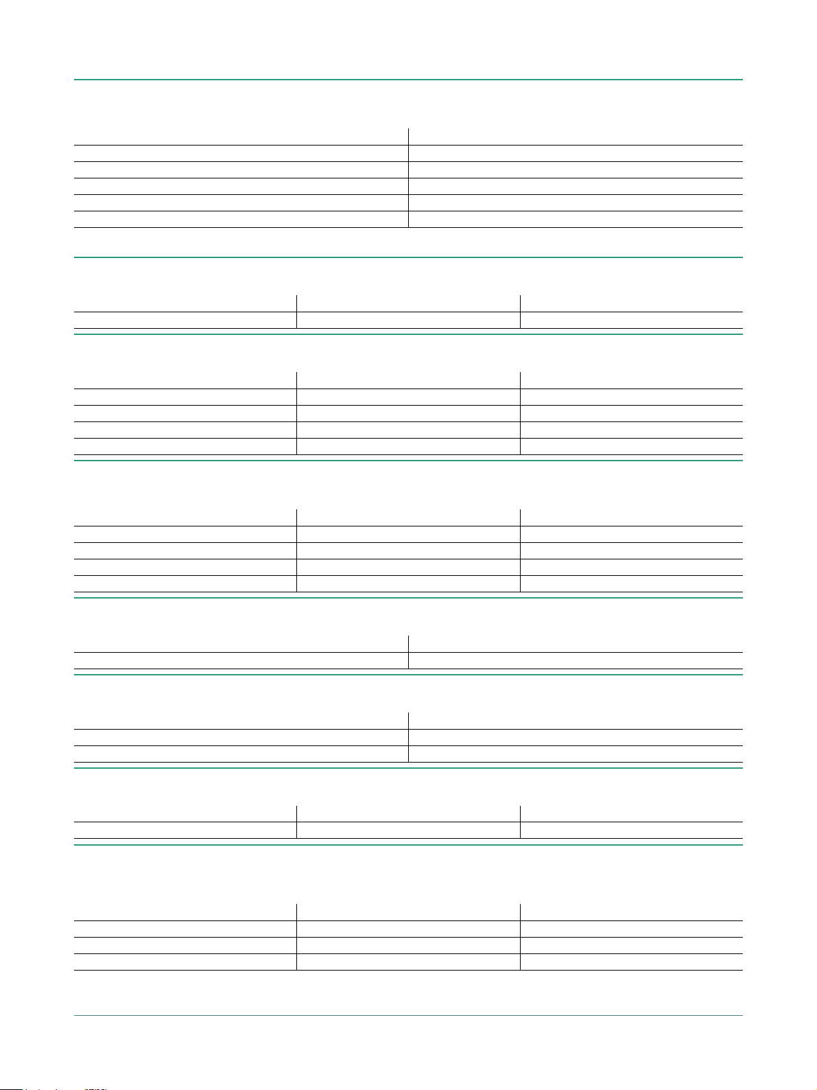
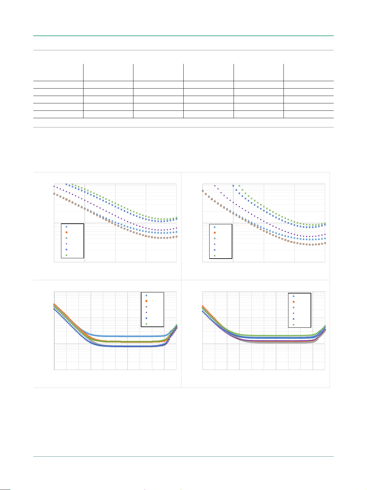
MS46131A-010 VNA System Performance with Manual Cal Kits
Error-Corrected Specifications
With calibration using TOSLN50A-8 or TOSLNF50A-8 N type connector calibration kits.
a
Frequency Range
Directivity
(dB)
Source Match
(dB)
Load Match
(dB)
Reflection Tracking
(dB)
1 MHz to 6 GHz ≥ 42 ≥ 33 ≥ 41 ± 0.15 ±0.06
> 6 GHz to 8 GHz ≥ 37 ≥ 33 ≥ 36 ± 0.15 ±0.06
a. Characteristic performance.
Measurement Uncertainties
The graphs give measurement uncertainties after the above error-corrected calibration. The errors are a worst-case contribution of residual directivity,
load and source match, frequency response and isolation, network analyzer dynamic accuracy, and connector repeatability. 10 Hz IF Bandwidth is used.
For transmission uncertainties, it is assumed that S11 = S22 = 0. A nominal amount of time drift is included in the computation as is consistent with the
use of phase compensation mode. Without phase compensation, uncertainties hold, but for a shorter amount of time/temperature change after
calibration. For reflection uncertainties, it is assumed that S
other conditions, please use our free Exact Uncertainty Calculator software, available for download from the Anritsu web site at
= 0. All calibrations and measurements were performed at default port power. For
21=S12
Transmission
a
Tracking
www.anritsu.com
a
(dB)
.
ME7868A TDS PN: 11410-02824 Rev. B 7 of 28
ME7868A Specifications
0.1
1
10
-40 -30 -20 -10 0
Uncertainty (dB)
Device reŇecƟon (dB)
ReŇecƟon magnitude uncertainty
1 MHz
10 MHz
10 GHz
20 GHz
1
10
100
-40 -30 -20 -10 0
Uncertainty (deg)
Device reŇecƟon (dB)
ReŇecƟon phase uncertainty
1 MHz
10 MHz
10 GHz
20 GHz
0.01
0.1
1
10
-90 -80 -70 -60 -50 -40 -30 -20 -10 0 10
Uncertainty (dB)
Device transmission (dB)
Transmission magnitude uncertainty
1 MHz
10 MHz
10 GHz
20 GHz
0.1
1
10
100
-90 -80 -70 -60 -50 -40 -30 -20 -10 0 10
Uncertainty (deg)
Device transmission (dB)
Transmission phase uncertainty
1 MHz
10 MHz
10 GHz
20 GHz
MS46131A-020 VNA System Performance with Manual Cal Kits
Error-Corrected Specifications
With calibration using the TOSLK50A-20 or TOSLKF50A-20 K type connector calibration kits.
a
Frequency Range
Directivity
(dB)
Source Match
(dB)
Load Match
(dB)
Reflection Tracking
(dB)
1 MHz to 10 GHz ≥ 42 ≥ 33 ≥ 41 ± 0.15 ±0.06
> 10 GHz to 20 GHz ≥ 36 ≥ 26 ≥ 35 ± 0.15 ±0.06
a. Characteristic performance.
Measurement Uncertainties
The graphs give measurement uncertainties after the above error-corrected calibration. The errors are a worst-case contribution of residual directivity,
load and source match, frequency response and isolation, network analyzer dynamic accuracy, and connector repeatability. 10 Hz IF Bandwidth is used.
For transmission uncertainties, it is assumed that S11 = S22 = 0. A nominal amount of time drift is included in the computation as is consistent with the
use of phase compensation mode. Without phase compensation, uncertainties hold, but for a shorter amount of time/temperature change after
calibration. For reflection uncertainties, it is assumed that S
other conditions, please use our free Exact Uncertainty Calculator software, available for download from the Anritsu web site at
= 0. All calibrations and measurements were performed at default port power. For
21=S12
Transmission
a
Tracking
www.anritsu.com
a
(dB)
.
8 of 28 PN: 11410-02824 Rev. B ME7868A TDS
Specifications ME7868A
0.1
1
10
-40 -30 -20 -10 0
Uncertainty (dB)
Device reŇecƟon (dB)
ReŇecƟon magnitude uncertainty
1 MHz
10 MHz
10 GHz
20 GHz
40 GHz
43.5 GHz
1
10
100
-40 -30 -20 -10 0
Uncertainty (deg)
Device reŇecƟon (dB)
ReŇecƟon phase uncertainty
1 MHz
10 MHz
10 GHz
20 GHz
40 GHz
43.5 GHz
0.01
0.1
1
10
-90 -80 -70 -60 -50 -40 -30 -20 -10 0 10
Uncertainty (dB)
Device transmission (dB)
Transmission magnitude uncertainty
1 MHz
10 MHz
10 GHz
20 GHz
40 GHz
43.5 GHz
0.1
1
10
100
-90 -80 -70 -60 -50 -40 -30 -20 -10 0 10
Uncertainty (deg)
Device transmission (dB)
Transmission phase uncertainty
1 MHz
10 MHz
10 GHz
20 GHz
40 GHz
43.5 GHz
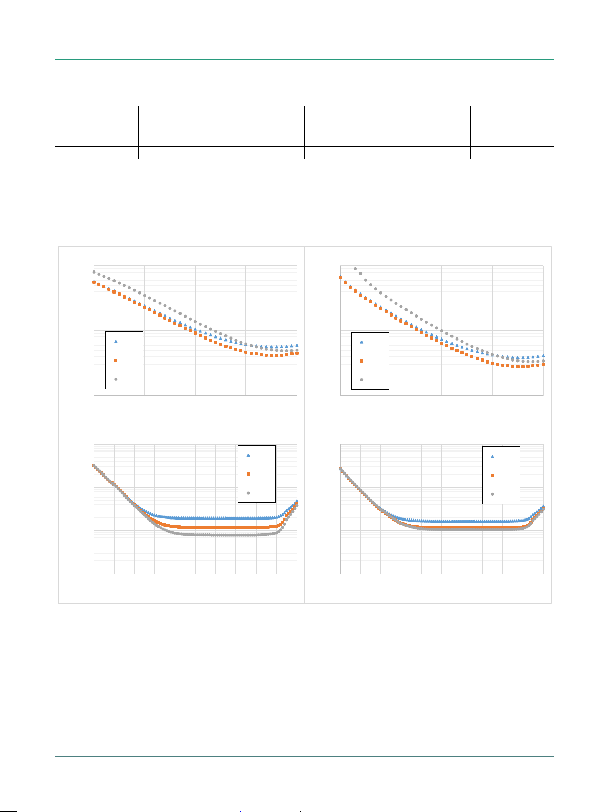
MS46131A-043 VNA System Performance with Manual Cal Kits
Error-Corrected Specifications
With calibration using TOSLK50A-43.5 or TOSLKF50A-43.5 K type connector calibration kits with generic calibration coefficients.
a
Frequency Range
Directivity
(dB)
Source Match
(dB)
Load Match
(dB)
Reflection Tracking
(dB)
1 MHz to 10 GHz ≥ 42 ≥ 33 ≥ 41 ± 0.15 ±0.06
> 10 GHz to 20 GHz ≥ 36 ≥ 26 ≥ 35 ± 0.15 ±0.06
> 20 GHz to 30 GHz ≥ 32 ≥ 22 ≥ 31 ± 0.15 ±0.06
> 30 GHz to 40 GHz ≥ 30 ≥ 20 ≥ 29 ± 0.15 ±0.06
> 40 GHz to 43.5 GHz ≥ 28 ≥ 20 ≥ 27 ± 0.2 ±0.16
a. Characteristic performance.
Measurement Uncertainties
The graphs give measurement uncertainties after the above error-corrected calibration. The errors are a worst-case contribution of residual directivity,
load and source match, frequency response and isolation, network analyzer dynamic accuracy, and connector repeatability. 10 Hz IF Bandwidth is used.
For transmission uncertainties, it is assumed that S11 = S22 = 0. A nominal amount of time drift is included in the computation as is consistent with the
use of phase compensation mode. Without phase compensation, uncertainties hold, but for a shorter amount of time/temperature change after
calibration. For reflection uncertainties, it is assumed that S
other conditions, please use our free Exact Uncertainty Calculator software, available for download from the Anritsu web site at
= 0. All calibrations and measurements were performed at default port power. For
21=S12
Transmission
a
Tracking
www.anritsu.com
a
(dB)
.
ME7868A TDS PN: 11410-02824 Rev. B 9 of 28

ME7868A Specifications
0.1
1
10
-40-30-20-10 0
Uncertainty (dB)
Device reŇecƟon (dB)
ReŇecƟon magnitude uncertainty
1 MHz
10 MHz
10 GHz
20 GHz
40 GHz
43.5 GHz
1
10
100
-40 -30 -20 -10 0
Uncertainty (deg)
Device reŇecƟon (dB)
ReŇecƟon phase uncertainty
1 MHz
10 MHz
10 GHz
20 GHz
40 GHz
43.5 GHz
0.01
0.1
1
10
-90 -80 -70 -60 -50 -40 -30 -20 -10 0 10
Uncertainty (dB)
Device transmission (dB)
Transmission magnitude uncertainty
1 MHz
10 MHz
10 GHz
20 GHz
40 GHz
43.5 GHz
0.1
1
10
100
-90-80-70-60-50-40-30-20-10 0 10
Uncertainty (deg)
Device transmission (dB)
Transmission phase uncertainty
1 MHz
10 MHz
10 GHz
20 GHz
40 GHz
43.5 GHz
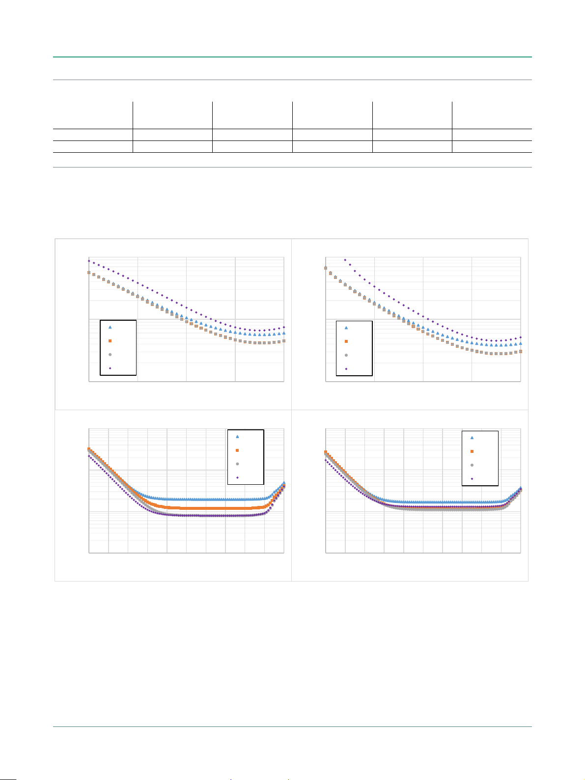
MS46131A-043 VNA System Performance with Manual Cal Kits
Error-Corrected Specifications
With calibration using TOSLK50A-43.5 or TOSLKF50A-43.5 K type connector calibration kits with .s1p definitions.
a
Frequency Range
Directivity
(dB)
Source Match
(dB)
Load Match
(dB)
Reflection Tracking
(dB)
1 MHz to 50 MHz ≥ 45 ≥ 45 ≥ 44 ± 0.15 ±0.06
> 0.05 GHz to 10 GHz ≥ 45 ≥ 45 ≥ 44 ± 0.15 ±0.06
> 10 GHz to 20 GHz ≥ 45 ≥ 45 ≥ 44 ± 0.15 ±0.06
> 20 GHz to 30 GHz ≥ 45 ≥ 44 ≥ 44 ± 0.15 ±0.06
> 30 GHz to 40 GHz ≥ 45 ≥ 42 ≥ 44 ± 0.15 ±0.06
> 40 GHz to 43.5 GHz ≥ 42 ≥ 41 ≥ 41 ± 0.2 ±0.16
a. Characteristic performance.
Measurement Uncertainties
The graphs give measurement uncertainties after the above error-corrected calibration. The errors are a worst-case contribution of residual directivity,
load and source match, frequency response and isolation, network analyzer dynamic accuracy, and connector repeatability. 10 Hz IF Bandwidth is used.
For transmission uncertainties, it is assumed that S11 = S22 = 0. A nominal amount of time drift is included in the computation as is consistent with the
use of phase compensation mode. Without phase compensation, uncertainties hold, but for a shorter amount of time/temperature change after
calibration. For reflection uncertainties, it is assumed that S
other conditions, please use our free Exact Uncertainty Calculator software, available for download from the Anritsu web site at
= 0. All calibrations and measurements were performed at default port power. For
21=S12
Transmission
a
Tracking
www.anritsu.com
a
(dB)
.
10 of 28 PN: 11410-02824 Rev. B ME7868A TDS

Specifications ME7868A
0.1
1
10
-40 -30 -20 -10 0
Uncertainty (dB)
Device reŇecƟon (dB)
ReŇecƟon magnitude uncertainty
1 MHz
10 MHz
8 GHz
1
10
100
-40 -30 -20 -10 0
Uncertainty (deg)
Device reŇecƟon (dB)
ReŇecƟon phase uncertainty
1 MHz
10 MHz
8 GHz
0.01
0.1
1
10
-90 -80 -70 -60 -50 -40 -30 -20 -10 0 10
Uncertainty (dB)
Device transmission (dB)
Transmission magnitude uncertainty
1 MHz
10 MHz
8 GHz
0.1
1
10
100
-90 -80 -70 -60 -50 -40 -30 -20 -10 0 10
Uncertainty (deg)
Device transmission (dB)
Transmission phase uncertainty
1 MHz
10 MHz
8 GHz
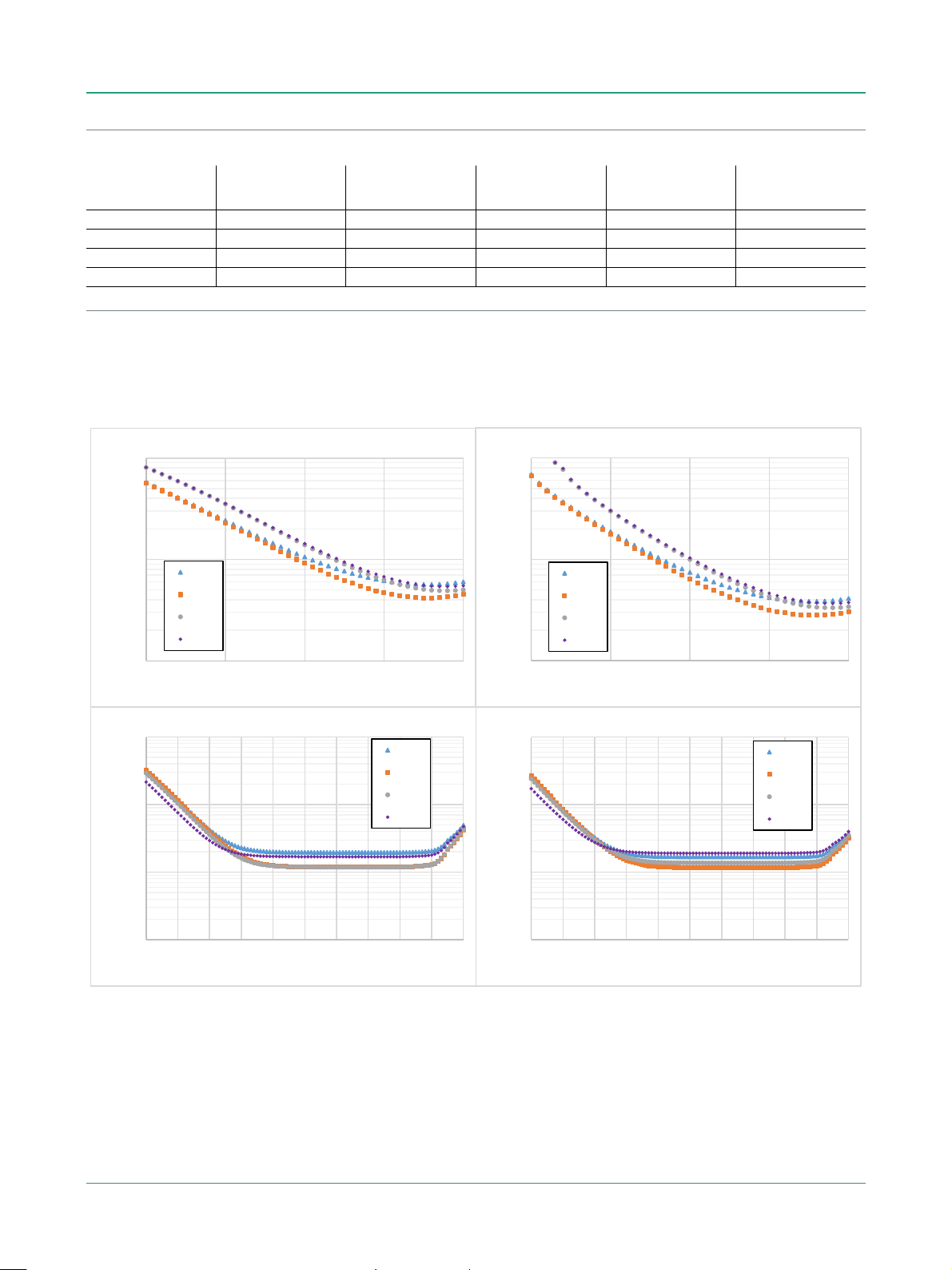
MS46131A-010 VNA System Performance with SmartCal™
Error-Corrected Specifications
With calibration using the 2-port MN25208A SmartCal™ automatic calibration kit with connector options MN25208A-001, -002, -003
a
Transmission
Tracking
(dB)
Frequency Range
Directivity
(dB)
Source Match
(dB)
Load Match
(dB)
a
Reflection Tracking
(dB)
1 MHz to 1 GHz ≥ 42 ≥ 35 ≥ 41 ± 0.15 ±0.06
> 1 GHz to 5 GHz ≥ 42 ≥ 35 ≥ 41 ± 0.08 ±0.08
> 5GHz to 8 GHz ≥ 36 ≥ 35 ≥ 36 ± 0.1 ±0.08
a. Characteristic performance.
Measurement Uncertainties
The graphs give measurement uncertainties after the above error-corrected calibration. The errors are a worst-case contribution of residual directivity,
load and source match, frequency response and isolation, network analyzer dynamic accuracy, and connector repeatability. 10 Hz IF Bandwidth is used.
For transmission uncertainties, it is assumed that S11 = S22 = 0. A nominal amount of time drift is included in the computation as is consistent with the
use of phase compensation mode. Without phase compensation, uncertainties hold, but for a shorter amount of time/temperature change after
calibration. For reflection uncertainties, it is assumed that S
other conditions, please use our free Exact Uncertainty Calculator software, available for download from the Anritsu web site at
= 0. All calibrations and measurements were performed at default port power. For
21=S12
www.anritsu.com
a
.
ME7868A TDS PN: 11410-02824 Rev. B 11 of 28

ME7868A Specifications
0.1
1
10
-40-30-20-10 0
Uncertainty (dB)
Device reŇecƟon (dB)
ReŇecƟon magnitude uncertainty
1 MHz
10 MHz
8 GHz
1
10
100
-40 -30 -20 -10 0
Uncertainty (deg)
Device reŇecƟon (dB)
ReŇecƟon phase uncertainty
1 MHz
10 MHz
8 GHz
0.01
0.1
1
10
-90 -80 -70 -60 -50 -40 -30 -20 -10 0 10
Uncertainty (dB)
Device transmission (dB)
Transmission magnitude uncertainty
1 MHz
10 MHz
8 GHz
0.1
1
10
100
-90 -80 -70 -60 -50 -40 -30 -20 -10 0 10
Uncertainty (deg)
Device transmission (dB)
Transmission phase uncertainty
1 MHz
10 MHz
8 GHz
MS46131A-010 VNA System Performance with SmartCal™
Error-Corrected Specifications
With calibration using the 4-port MN25408A SmartCal™ automatic calibration kit with connector options MN25408A-001, -002, -003
a
Transmission
Tracking
(dB)
Frequency Range
Directivity
(dB)
Source Match
(dB)
Load Match
(dB)
a
Reflection Tracking
(dB)
1 MHz to 1 GHz ≥ 42 ≥ 35 ≥ 41 ± 0.15 ±0.2
> 1 GHz to 5 GHz ≥ 37 ≥ 35 ≥ 36 ± 0.08 ±0.2
> 5 GHz to 8 GHz ≥ 37 ≥ 32 ≥ 36 ± 0.2 ±0.2
a. Characteristic performance.
Measurement Uncertainties
The graphs give measurement uncertainties after the above error-corrected calibration. The errors are a worst-case contribution of residual directivity,
load and source match, frequency response and isolation, network analyzer dynamic accuracy, and connector repeatability. 10 Hz IF Bandwidth is used.
For transmission uncertainties, it is assumed that S11 = S22 = 0. A nominal amount of time drift is included in the computation as is consistent with the
use of phase compensation mode. Without phase compensation, uncertainties hold, but for a shorter amount of time/temperature change after
calibration. For reflection uncertainties, it is assumed that S
other conditions, please use our free Exact Uncertainty Calculator software, available for download from the Anritsu web site at
= 0. All calibrations and measurements were performed at default port power. For
21=S12
www.anritsu.com
a
.
12 of 28 PN: 11410-02824 Rev. B ME7868A TDS
Specifications ME7868A
0.01
0.1
1
10
-90 -80 -70 -60 -50 -40 -30 -20 -10 0 10
Uncertainty (dB)
Device transmission (dB)
Transmission magnitude uncertainty
1 MHz
10 MHz
10 GHz
20 GHz
0.1
1
10
100
-90 -80 -70 -60 -50 -40 -30 -20 -10 0 10
Uncertainty (deg)
Device transmission (dB)
Transmission phase uncertainty
1 MHz
10 MHz
10 GHz
20 GHz
0.1
1
10
-40 -30 -20 -10 0
Uncertainty (dB)
Device reŇecƟon (dB)
ReŇecƟon magnitude uncertainty
1 MHz
10 MHz
10 GHz
20 GHz
1
10
100
-40 -30 -20 -10 0
Uncertainty (deg)
Device reŇecƟon (dB)
ReŇecƟon phase uncertainty
1 MHz
10 MHz
10 GHz
20 GHz
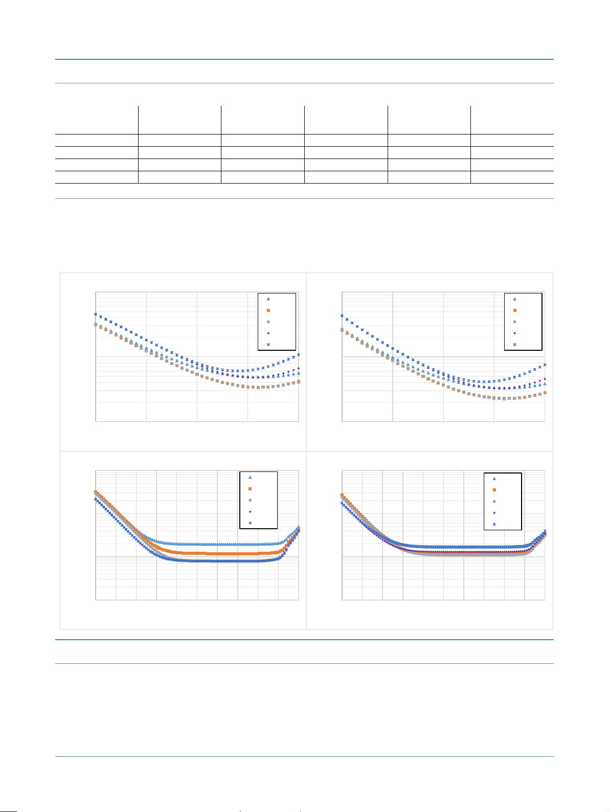
MS46131A-010, MS46131A-020 VNA System Performance with SmartCal™
Error-Corrected Specifications
With calibration using the 2-port MN25218A SmartCal™ automatic calibration kit.
a
Frequency Range
Directivity
(dB)
Source Match
(dB)
Load Match
(dB)
Reflection Tracking
(dB)
1 MHz to 1 GHz ≥ 42 ≥ 33 ≥ 41 ± 0.15 ±0.1
> 1 GHz to 10 GHz ≥ 37 ≥ 33 ≥ 41 ± 0.15 ±0.1
> 10 GHz to 18 GHz ≥ 37 ≥ 33 ≥ 35 ± 0.15 ±0.1
> 18 GHz to 20 GHz ≥ 37 ≥ 33 ≥ 35 ± 0.20 ±0.15
a. Characteristic performance.
Measurement Uncertainties
The graphs give measurement uncertainties after the above error-corrected calibration. The errors are a worst-case contribution of residual directivity,
load and source match, frequency response and isolation, network analyzer dynamic accuracy, and connector repeatability. 10 Hz IF Bandwidth is used.
For transmission uncertainties, it is assumed that S11 = S22 = 0. A nominal amount of time drift is included in the computation as is consistent with the
use of phase compensation mode. Without phase compensation, uncertainties hold, but for a shorter amount of time/temperature change after
calibration. For reflection uncertainties, it is assumed that S
other conditions, please use our free Exact Uncertainty Calculator software, available for download from the Anritsu web site at
= 0. All calibrations and measurements were performed at default port power. For
21=S12
Transmission
a
Tracking
www.anritsu.com
a
(dB)
.
ME7868A TDS PN: 11410-02824 Rev. B 13 of 28

ME7868A Specifications
0.1
1
10
-40-30-20-10 0
Uncertainty (dB)
Device reŇecƟon (dB)
ReŇecƟon magnitude uncertainty
1 MHz
10 MHz
10 GHz
20 GHz
1
10
100
-40 -30 -20 -10 0
Uncertainty (deg)
Device reŇecƟon (dB)
ReŇecƟon phase uncertainty
1 MHz
10 MHz
10 GHz
20 GHz
0.01
0.1
1
10
-90 -80 -70 -60 -50 -40 -30 -20 -10 0 10
Uncertainty (dB)
Device transmission (dB)
Transmission magnitude uncertainty
1 MHz
10 MHz
10 GHz
20 GHz
0.1
1
10
100
-90 -80 -70 -60 -50 -40 -30 -20 -10 0 10
Uncertainty (deg)
Device transmission (dB)
Transmission phase uncertainty
1 MHz
10 MHz
10 GHz
20 GHz
MS46131A-010, MS46131A-020 VNA System Performance with SmartCal™
Error-Corrected Specifications
With calibration using the 4-port MN25418A SmartCal™ automatic calibration kit.
a
Frequency Range
Directivity
(dB)
Source Match
(dB)
Load Match
(dB)
Reflection Tracking
(dB)
1 MHz to 10 MHz ≥ 40 ≥ 31 ≥ 41 ± 0.15 ±0.20
> 10 MHz to 6 GHz ≥ 40 ≥ 31 ≥ 41 ± 0.15 ±0.15
> 6 GHz to 18 GHz ≥ 35 ≥ 31 ≥ 36 ± 0.20 ±0.20
> 18 GHz to 20 GHz ≥ 35 ≥ 31 ≥ 33 ± 0.20 ±0.25
a. Characteristic performance.
Measurement Uncertainties
The graphs give measurement uncertainties after the above error-corrected calibration. The errors are a worst-case contribution of residual directivity,
load and source match, frequency response and isolation, network analyzer dynamic accuracy, and connector repeatability. 10 Hz IF Bandwidth is used.
For transmission uncertainties, it is assumed that S11 = S22 = 0. A nominal amount of time drift is included in the computation as is consistent with the
use of phase compensation mode. Without phase compensation, uncertainties hold, but for a shorter amount of time/temperature change after
calibration. For reflection uncertainties, it is assumed that S
other conditions, please use our free Exact Uncertainty Calculator software, available for download from the Anritsu web site at
= 0. All calibrations and measurements were performed at default port power. For
21=S12
Transmission
a
Tracking
www.anritsu.com
a
(dB)
.
14 of 28 PN: 11410-02824 Rev. B ME7868A TDS
Specifications ME7868A
0.1
1
10
-40 -30 -20 -10 0
Uncertainty (dB)
Device reŇecƟon (dB)
ReŇecƟon magnitude uncertainty
1 MHz
10 MHz
10 GHz
20 GHz
40 GHz
1
10
100
-40 -30 -20 -10 0
Uncertainty (deg)
Device reŇecƟon (dB)
ReŇecƟon phase uncertainty
1 MHz
10 MHz
10 GHz
20 GHz
40 GHz
0.01
0.1
1
10
-90 -80 -70 -60 -50 -40 -30 -20 -10 0 10
Uncertainty (dB)
Device transmission (dB)
Transmission magnitude uncertainty
1 MHz
10 MHz
10 GHz
20 GHz
40 GHz
0.1
1
10
100
-90 -80 -70 -60 -50 -40 -30 -20 -10 0 10
Uncertainty (deg)
Device transmission (dB)
Transmission phase uncertainty
1 MHz
10 MHz
10 GHz
20 GHz
40 GHz
MS46131A-043 VNA System Performance with Precision AutoCal™
Error-Corrected Specifications
With calibration using the 36585K automatic calibration kit with type K connectors.
a
Frequency Range
Directivity
(dB)
Source Match
(dB)
Load Match
(dB)
Reflection Tracking
(dB)
1 MHz to < 10 GHz ≥ 50 ≥ 49 ≥ 42 ± 0.15 ±0.06
10 GHz to < 20 GHz ≥ 45 ≥ 49 ≥ 36 ± 0.15 ±0.06
20 GHz to < 30 GHz ≥ 45 ≥ 45 ≥ 36 ± 0.10 ±0.06
30 GHz to 40 GHz ≥ 45 ≥ 45 ≥ 30 ± 0.10 ±0.06
a. Characteristic performance.
Measurement Uncertainties
The graphs give measurement uncertainties after the above error-corrected calibration. The errors are a worst-case contribution of residual directivity,
load and source match, frequency response and isolation, network analyzer dynamic accuracy, and connector repeatability. 10 Hz IF Bandwidth is used.
For transmission uncertainties, it is assumed that S11 = S22 = 0. A nominal amount of time drift is included in the computation as is consistent with the
use of phase compensation mode. Without phase compensation, uncertainties hold, but for a shorter amount of time/temperature change after
calibration. For reflection uncertainties, it is assumed that S
other conditions, please use our free Exact Uncertainty Calculator software, available for download from the Anritsu web site at
= 0. All calibrations and measurements were performed at default port power. For
21=S12
Transmission
a
Tracking
www.anritsu.com
a
(dB)
.
Measurement Throughput
Measurement Speed
170 µs/point (1-port calibrated data, typical)
230 µs/point (2-port calibrated data, typical)
Per point single sweep time, including placing measurement data into memory. Average of narrow, mid,
and wide frequency span sweeps. Measured with 300 kHz IFBW, 1601 points. Timing dependent on external
computer configuration. Measurements taken with an Intel® Core™ i5-6300U processor running
Windows 10 with 4 GB of RAM and 60 GB of free hard disk space.
ME7868A TDS PN: 11410-02824 Rev. B 15 of 28

ME7868A Specifications
Standard Capabilities
Operating Frequencies
Applies to all PhaseLync cable lengths.
ME7868A-010 1 MHz to 8 GHz
ME7868A-020 1 MHz to 20 GHz
ME7868A-043 1 MHz to 43.5 GHz
Measurement Parameters
2-Port Measurements S11, S21, S22, S12, and any user-defined combination of a1, a2, b1, b2, 1
Domains Frequency Domain, Time (Distance) Domain (Option 002)
Sweeps
Frequency Sweep Types Linear, Log, CW, or Segmented
Display Graphs
Single Rectilinear Graph Types Log Magnitude, Phase, Group Delay, Linear Magnitude, Real, Imaginary, SWR, Impedance
Dual Rectilinear Graph Types Log Mag and Phase, Linear Mag and Phase, Real and Imaginary
Circular Graph Types Smith Chart (Impedance), Polar
Measurements Data Points
Maximum Data Points 2 to 16,001 points
Limit Lines
Limit Lines Single or segmented. 2 limit lines per trace. 50 segments per trace.
Single Limit Readouts Uses interpolation to determine the intersection frequency.
Test Limits Both single and segmented limits can be used for PASS/FAIL testing.
Ripple Limit Lines
Limit Lines Single or segmented. 2 limit lines per trace. 50 segments per trace.
Ripple Value Absolute Value or Margin
Test Limits Both single and segmented limits can be used for PASS/FAIL testing.
Maximum Efficiency Analysis, Mixed-mode SDD, SDC, SCD, SCC
Averaging
Point-by-Point Point-by-point (default),
Sweep-by-Sweep Sweep-by-sweep,
IF Bandwidth
Reference Plane
Line Length or Time Delay The reference planes of a calibration or other normalization can be changed by entering a line length or
Dielectric Constants Dielectric constants may be entered for different media so the length entry can be physically meaningful.
Dispersion Modeling Dispersion modeling is used in the cases of microstrip and waveguide to take into account frequency
Attenuation Attenuation (with frequency slope) and constant phase offsets can be entered to better describe any
Auto Modes Automatic reference plane finding tools are available for phase alone or phase + magnitude. These routines
De-embedding For more complete reference plane manipulation, the full de-embedding system can also be used.
Measurement Frequency Range
Frequency Range Change Frequency range of the measurement can be narrowed within the calibration range without recalibration.
CW Mode CW mode permits single frequency measurements also without recalibration.
Interpolation Not Activated If interpolation is not activated, the subset frequency range is forced to use calibration frequency points.
Interpolation Activated If interpolation is activated, any frequency range that is a subset of the calibration frequency range can be
Group Delay
Group Delay Aperture Defined as the frequency span over which the phase change is computed at a given frequency point.
Aperture The aperture can be changed without recalibration.
Minimum Aperture The minimum aperture is the frequency range divided by the number of points in calibration and can be
Group Delay Range < 180° of phase change within the aperture
maximum number of averages = 200
maximum number of averages = 4096
10, 20, 50, 70, 100, 200, 300, 500, 700 Hz
1, 2, 3, 5, 7, 10, 20, 30, 50, 70, 100, 200, 300 kHz
time delay.
dependent phase velocities.
reference plane distortions. The frequency dependence exponent is changeable.
do a fitting process on phase or phase and magnitude to estimate the reference plane location and enter
correcting values.
used, but there may be some added interpolation error.
increased to 20 % of the frequency range.
16 of 28 PN: 11410-02824 Rev. B ME7868A TDS

Specifications ME7868A
Channels, Display, and Traces
Channels and Traces 16 channels, each with up to 16 traces
Display Colors Unlimited colors for data traces, memory, text, markers, graticules, and limit lines
Trace Memory and Math Up to 20 trace memories per channel can be used to store trace measurement data for later display or
Inter-trace Math Any two traces within a channel can be combined (via addition, subtraction, multiplication, or division) and
subtraction, addition, multiplication or division with current measurement data. The trace data can be saved
and recalled.
displayed on another trace. An equation editor mode is also available that allows the combination of trace
data, trace memory and S-parameter data in more complex equations. Over 30 built-in functions are
available. Simple editing tools and the ability to save/recall equations are also provided.
Scale Resolution
Markers
Marker Search and Tracking Search and/or track for minimum, maximum, peak, or target value. Multiple marker search ranges per trace
Other
S-Parameter Conversion Z Reflection Impedance
Minimum per division, varies with graph type.
Log Magnitude 0.001 dB
Linear Magnitude 10
Phase 0.01°
Group Delay 0.1 ps
Time 0.0001 ps
Distance 0.1
SWR 10
Power 0.01 dB
Markers 12 markers + 1 reference marker
Marker Coupling Coupled or decoupled
Marker Overlay Display markers on active trace only or
Marker Data Data displayed in graph area or in table form
Reference Marker Additional marker per trace for reference
Marker Statistics Mean, maximum, minimum, standard deviation
Filter Parameters Display bandwidth (user-selectable loss value), corner and center frequencies, loss, Q, and shape factors.
U
m
U
on all traces when multiple trace responses are present on the same trace
Per trace or over a marker region
are available.
Z Transmission Impedance
Y Reflection Admittance
Y Transmission Admittance
1/S
ME7868A TDS PN: 11410-02824 Rev. B 17 of 28

ME7868A Specifications
Calibration and Correction Capabilities
Calibration Methods
Short-Open-Load-Through (SOLT)
Offset-Short-Offset-Short-Load-Through (SSLT)
Triple-Offset-Short-Through (SSST)
Short-Open-Load-Reciprocal (SOLR)
Line-Reflect-Line (LRL) / Line-Reflect-Match (LRM)
Thru-Reflect-Line (TRL) / Thru-Reflect-Match (TRM)
SmartCal™
AutoCal™
Thru Update available
Secondary match correction available for improved low insertion loss measurements
Correction Models
1-Port (S11, S22, or both)
2-Port (Forward, Reverse, or both directions)
Transmission Frequency Response (Forward, Reverse, or both directions)
Reflection Frequency Response (S11, S22, or both)
Coefficients for Calibration Standards
Use the Anritsu calibration kit USB memory device to load kit coefficients and characterization files.
Enter coefficients into user-defined locations.
Use complex load models.
Interpolation
Adapter Removal Calibration
Dispersion Compensation
Embedding/De-embedding
De-embedding De-embedding is generally used for removal of test fixture contributions, modeled networks, and other
Embedding Similarly, the Embedding function can be used to simulate matching circuits for optimizing amplifier
Multiple Networks Multiple networks can be embedded/de-embedded and changing the port and network orientations is
Extraction Utility An extraction utility is part of this package that allows easier computation of de-embedding files based on
Impedance Conversion
Allows interpolation between calibration frequency points.
Characterizes and “removes” an adapter that is used during calibration that will not be used for subsequent
device measurements; for accurate measurement of non-insertable devices.
Selectable as Coaxial, other non-dispersive (e.g., for coplanar waveguide), Waveguide, or Microstrip
The ME7868A is equipped with an Embedding/De-embedding system.
networks described by S-parameters (s2p files) from measurements.
designs or simply adding effects of a known structure to a measurement.
handled easily.
additional calibration steps and measurements.
Allows entry of different reference impedances (complex values) for different ports
Optional Capabilities
Time Domain Measurements, MS46131A-002 Displays all S-parameters and overlays with Frequency Domain, Low-pass Mode with added harmonics
frequency list flexibility, Band-pass Mode, Phasor Impulse Mode, Windowing, Gating (pass-band or
reject-band), and Frequency with Time Gate. Option must be enabled on both MS46131As in the ME7868A
configuration for time domain to be enabled for the 2-port VNA.
Remote Operability
ShockLine supports several remote operability options.
Communication Type Data Format Performance Description
Drivers IVI-C drivers are available for download from the Anritsu website. The IVI-C package supports National Instruments
Triggering Start Trigger Software and Digital Edge
LabVIEW and LabWindows, C#, .NET, MATLAB, and Python programming environments.
Input Range +3.3 V logic level (+5 V tolerant)
Minimum Trigger Width 50 ns
Trigger Delay 6 µs, typical
18 of 28 PN: 11410-02824 Rev. B ME7868A TDS

Specifications ME7868A
Standard Device Connections
2 Meter
ME7868A-010-2: 1 MHz to 8 GHz
ME7868A-020-2: 1 MHz to 20 GHz
ME7868A-043-2: 1 MHz to 43.5 GHz
Solution includes:
• Two MS46131A Modular 1-Port VNAs:
- Each VNA must have one frequency option 010 / 020 / 043
- Each VNA must have Option 012 PhaseLync
• One 2000-2011-R (2 meter) PhaseLync Optical Cable (PLO)
• One 2000-2013-R (2 meter) PhaseLync Electrical Cable (PLE)
• Windows PC is user supplied
ME7868A TDS PN: 11410-02824 Rev. B 19 of 28

ME7868A Specifications
Solution includes:
• Two MS46131A Modular 1-Port VNAs:
5 Meter
ME7868A-010-5: 1 MHz to 8 GHz
ME7868A-020-5: 1 MHz to 20 GHz
ME7868A-043-5: 1 MHz to 43.5 GHz
- Each VNA must have one frequency option 010 / 020 / 043
- Each VNA must have Option 012 PhaseLync
• One 2000-2012-R (5 meter) PhaseLync Optical Cable (PLO)
• One 2000-2014-R (5 meter) PhaseLync Electrical Cable (PLE)
• Two 3 meter USB extension cables
• Windows PC is user supplied
20 of 28 PN: 11410-02824 Rev. B ME7868A TDS

Specifications ME7868A
ME7868A TDS PN: 11410-02824 Rev. B 21 of 28

ME7868A Specifications
Solution includes:
• Two MS46131A Modular 1-Port VNAs:
- Each VNA must have one frequency option 010 / 020 / 043
- Each VNA must have Option 012 PhaseLync
25 Meter
ME7868A-010-25: 1 MHz to 8 GHz
ME7868A-020-25: 1 MHz to 20 GHz
ME7868A-043-25: 1 MHz to 43.5 GHz
• One 2000-2025-R (25 meter) PhaseLync Cable Assembly
• One 2000-2007-R PhaseLync Accessory Kit:
- Two MN25131A Multifunction Extenders
- USB Monitor
- USB Keyboard/Mouse
- Two USB Headsets
- Extender Connection Cables
• Windows PC is user supplied
For distances > 25 meters, please contact the factory.
22 of 28 PN: 11410-02824 Rev. B ME7868A TDS

Specifications ME7868A
Test Port
10 MHz In
External Trigger Input/Output
ME7868A-010 N(f)
ME7868A-020 Ruggedized K(m)
ME7868A-043 Ruggedized Extended-K™(m)
Damage Input Levels +23 dBm maximum,
Signal presence is auto-sensing (better than 10 ppm frequency accuracy is recommended).
Connector Type SMA(f)
Signal +0 dBm, typical; 50 Ω, nominal
External trigger input should be applied to the master MS46131A in the ME7868A.
External trigger output may be accessed on the slave MS46131A.
Connector Type SMA(f)
Voltage Input 0 to 3.3 V input (5 V tolerant)
Impedance High impedance (> 100 kΩ)
Pulse Width 50 ns minimum input pulse width
µs
µs,
typical
typical
Trigger Delay 6
Voltage Output 0 to 3.3 V (HCMOS logic)
Drive Current 12 mA maximum
Pulse Width 1
Recommended External PC Configuration
CPU Intel® Core™ i5-6300U Processor
RAM 4 GB
Disk 120 GB
DirectX Version 9 with Windows Display Driver Model (WDDM) installed
ShockLine software is compatible with Windows® 7,8, 8.1, or 10; 32 or 64 bit operating systems
USB One USB 2.0 (or higher) type A port per MS46131A used
To increase the number of USB ports available, an externally powered USB hub may also be used.
±
50 VDC maximum
Regulatory Compliance
European Union EMC 2014/30/EU, EN 61326:2013, CISPR 11/EN 55011, IEC/EN 61000-4-2/3/4/5/6/8/11
Australia and New Zealand RCM AS/NZS 4417:2012
South Korea KCC-REM-A21-0004
Environmental
Operating Temperature Range -10 ºC to 55 ºC
Storage Temperature Range –51 ºC to 71 ºC
Maximum Relative Humidity 95 % RH at 30 ºC, non-condensing
Warranty
MS46131A and Built-In Options 3 years from the date of shipment (standard warranty)
MN25131A Typically 1 year from the date of shipment
PhaseLync cables Typically 1 year from the date of shipment
Calibration Kits Typically 1 year from the date of shipment
Test Port Cables Typically 1 year from the date of shipment
Warranty Options Additional warranty available
Low Voltage Directive 2014/35/EU
Safety EN 61010-1:2010
RoHS Directive 2011/65/EU applies to instruments with CE marking placed on the market after July 22, 2017
MIL-PRF-28800F Class 2
Altitude 4600 meters, operating and non-operating
ME7868A TDS PN: 11410-02824 Rev. B 23 of 28

ME7868A Specifications
Ordering Information
ME7868A 2-Port VNA
2 meter ME7868A-010-2: 2-port Modular ME7868A Vector Network Analyzer, 1 MHz to 8 GHz
ME7868A-020-2: 2-port Modular ME7868A Vector Network Analyzer, 1 MHz to 20 GHz
ME7868A-043-2: 2-port Modular ME7868A Vector Network Analyzer, 1 MHz to 43.5 GHz
5 meter ME7868A-010-5: 2-port Modular ME7868A Vector Network Analyzer, 1 MHz to 8 GHz
ME7868A-020-5: 2-port Modular ME7868A Vector Network Analyzer, 1 MHz to 20 GHz
ME7868A-043-5: 2-port Modular ME7868A Vector Network Analyzer, 1 MHz to 43.5 GHz
1
25 meter
ME7868A-010-25: 2-port Modular ME7868A Vector Network Analyzer, 1 MHz to 8 GHz
ME7868A-020-25: 2-port Modular ME7868A Vector Network Analyzer, 1 MHz to 20 GHz
ME7868A-043-25: 2-port Modular ME7868A Vector Network Analyzer, 1 MHz to 43.5 GHz
VNA Options
Main Options MS46131A-002, Time Domain with Time Gating
Calibration Options VNA performance is determined by the verified performance of the two MS46131As in the configuration.
Calibration options offered for the MS46131A only.
MS46131A-098, Standard Calibration, ISO 17025 compliant, without data
MS46131A-099, Premium Calibration, ISO 17025 compliant, with data
Precision Automatic Calibrator Modules
MN25208A 2-port USB SmartCal Module, 300 kHz to 8.5 GHz
MN25408A 4-port USB SmartCal Module, 300 kHz to 8.5 GHz
MN25218A
MN25418A 4-port USB SmartCal Module, 300 kHz to 20 GHz
36585K-2M K Connector Precision AutoCal Module, 70 kHz to 40 GHz, K(m) to K(m)
36585K-2F K Connector Precision AutoCal Module, 70 kHz to 40 GHz, K(f) to K(f)
36585K-2MF K Connector Precision AutoCal Module, 70 kHz to 40 GHz, K(m) to K(f)
2000-1809-R Serial to USB Adapter (required for use with 36585 AutoCal module if control PC does not have a serial port)
(available with connector Options -001 N(f), -002 K(f), -003 3.5 mm(f))
(available with connector Options -001 N(f), -002 K(f), -003 3.5 mm(f))
2
2-port USB SmartCal Module, 300 kHz to 20 GHz
(available with connector Option -002 K(f))
(available with connector Option -002 K(f))
Mechanical Calibration Kits
3650A-1 SMA/3.5 mm Calibration Kit, With Sliding Loads, DC to 26.5 GHz, 50 Ω
3652A-1 K Connector Calibration Kit, With Sliding Loads, DC to 40 GHz, 50 Ω
OSLN50A-8 Precision N Male Open/Short/Load Mechanical Calibration Tee, DC to 8 GHz, 50 Ω
OSLNF50A-8 Precision N Female Open/Short/Load Mechanical Calibration Tee, DC to 8 GHz, 50 Ω
TOSLN50A-8 Precision N Male Through/Open/Short/Load Mechanical Calibration Tee, DC to 8 GHz, 50 Ω
TOSLNF50A-8 Precision N Female Through/Open/Short/Load Mechanical Calibration Tee, DC to 8 GHz, 50 Ω
OSLN50A-18 Precision N Male Open/Short/Load Mechanical Calibration Tee, DC to 18 GHz, 50 Ω
OSLNF50A-18 Precision N Female Open/Short/Load Mechanical Calibration Tee, DC to 18 GHz, 50 Ω
TOSLN50A-18 Precision N Male Through/Open/Short/Load Mechanical Calibration Tee, DC to 18 GHz, 50 Ω
TOSLNF50A-18 Precision N Female Through/Open/Short/Load Mechanical Calibration Tee, DC to 18 GHz, 50 Ω
TOSLK50A-20 Precision K Male Through/Open/Short/Load Mechanical Calibration Tee, DC to 20 GHz, 50 Ω
TOSLKF50A-20 Precision K Female Through/Open/Short/Load Mechanical Calibration Tee, DC to 20 GHz, 50 Ω
TOSLK50A-40 Precision K Male Through/Open/Short/Load Mechanical Calibration Tee, DC to 40 GHz, 50 Ω
TOSLKF50A-40 Precision K Female Through/Open/Short/Load Mechanical Calibration Tee, DC to 40 GHz, 50 Ω
TOSLK50A-43.5 Precision K Male Through/Open/Short/Load Mechanical Calibration Tee, DC to 43.5 GHz, 50 Ω
TOSLKF50A-43.5 Precision K Female Through/Open/Short/Load Mechanical Calibration Tee, DC to 43.5 GHz, 50 Ω
3650A SMA/3.5 mm Calibration Kit, Without Sliding Loads, DC to 26.5 GHz, 50 Ω
3652A K Connector Calibration Kit, Without Sliding Loads, DC to 40 GHz, 50 Ω
3653A N Connector Calibration Kit, Without Sliding Loads, DC to 18 GHz, 50 Ω
Includes .s1p files for data-based calibration support
Includes .s1p files for data-based calibration support
1. All 25 meter configurations come with additional components to enable long distance usage. These items include two MN25131A multi-function extenders, USB monitor, keyboard,
mouse, headset, and additional cabling to allow for communication and control from either side of the 25 meter setup.
2. Applies to Rev 2 SmartCal Modules. MN25218A with serial numbers < 1817999 operate from 1 MHz to 20 GHz.
24 of 28 PN: 11410-02824 Rev. B ME7868A TDS

Specifications ME7868A
Adapters
1091-26-R Adapter, SMA(m) to N(m), DC to 18 GHz, 50 Ω
1091-27-R Adapter, SMA(f) to N(m), DC to 18 GHz, 50 Ω
1091-80-R Adapter, SMA(m) to N(f), DC to 18 GHz, 50 Ω
1091-81-R Adapter, SMA(f) to N(f), DC to 18 GHz, 50 Ω
71693-R Ruggedized adapter, K(f) to N(f), DC to 18 GHz, 50 Ω
33KK50C Calibration Grade Adapter, DC to 43.5 GHz, K(m) to K(m), 50 Ω
33KKF50C Calibration Grade Adapter, DC to 43.5 GHz, K(m) to K(f), 50 Ω
33KFKF50C Calibration Grade Adapter, DC to 43.5 GHz, K(f) to K(f), 50 Ω
34NK50 Precision Adapter, N(m) to K(m), DC to 18 GHz, 50 Ω
34NKF50 Precision Adapter, N(m) to K(f), DC to 18 GHz, 50 Ω
34NFK50 Precision Adapter, N(f) to K(m), DC to 18 GHz, 50 Ω
34NFKF50 Precision Adapter, N(f) to K(f), DC to 18 GHz, 50 Ω
34VFK50A Precision Adapter, DC to 43.5 GHz, V(f) - K(m), 50 Ω
34VFKF50A Precision Adapter, DC to 43.5 GHz, V(f) - K(f), 50 Ω
34VK50A Precision Adapter, DC to 43.5 GHz, V(m) - K(m), 50 Ω
34VKF50A Precision Adapter, DC to 43.5 GHz, V(m) - K(f), 50 Ω
K220B Precision Adapter, DC to 40 GHz, K(m) to K(m), 50 Ω
K222B Precision Adapter, DC to 40 GHz, K(f) to K(f), 50 Ω
K224B Precision Adapter, DC to 40 GHz, K(m) to K(f), 50 Ω
Test Port Cables, Flexible, Ruggedized, Phase Stable
15 Series Cable Example
15NNF50-1.0B Test Port Cable, Flexible, Phase Stable, N(f) to N(m), 1.0 m
15NNF50-1.5B Test Port Cable, Flexible, Phase Stable, N(f) to N(m), 1.5 m
15NN50-1.0B Test Port Cable, Flexible, Phase Stable, N(m) to N(m), 1.0 m
15LL50-1.0A Test Port Cable, Armored, Phase Stable, DC to 20 GHz, 3.5 mm(m) to 3.5 mm(m), 1.0 m, 50
15LLF50-1.0A Test Port Cable, Armored, Phase Stable, DC to 20 GHz, 3.5 mm(m) to 3.5 mm(f), 1.0 m, 50
15KK50-1.0A Test Port Cable, Armored, Phase Stable, DC to 20 GHz, K(m) to K(m), 1.0 m, 50
15KKF50-1.0A Test Port Cable, Armored, Phase Stable, DC to 20 GHz, K(m) to K(f), 1.0 m, 50
Phase-Stable 18 GHz and 43.5 GHz Semi-Rigid Cables (Armored)
3670 Series Cable Example
3670N50-1 0.3 m (12”), DC to 18 GHz, N(f) to N(m), 50 Ω
3670NN50-1 0.3 m (12”), DC to 18 GHz, N(m) to N(m), 50 Ω
3670N50-2 0.6 m (24”), DC to 18 GHz, N(f) to N(m), 50 Ω
3670NN50-2 0.6 m (24”), DC to 18 GHz, N(m) to N(m), 50 Ω
3670K50A-1 0.3 m (12”), DC to 43.5 GHz, K(f) to K(m), 50 Ω
3670K50A-2 0.6 m (24”), DC to 43.5 GHz, K(f) to K(m), 50 Ω
Ω
Ω
Ω
Ω
ME7868A TDS PN: 11410-02824 Rev. B 25 of 28

ME7868A Specifications
Phase-Stable 20 GHz and 40 GHz Test Port Cables (Flexible)
3671 Series Cable Example 806-304-R Cable Example
3671KFS50-60 60 cm (23.6 in), DC to 20 GHz, K (f) to 3.5 mm (m), 50 Ω
3671KFSF50-60 60 cm (23.6 in), DC to 20 GHz, K (f) to 3.5 mm (f), 50 Ω
3671KFKF50-60 60 cm (23.6 in), DC to 40 GHz, K (f) to K (f), 50 Ω
3671KFK50-100 100 cm (39.4 in), DC to 40 GHz, K (f) to K (m), 50 Ω
806-304-R 36 in (91.5 cm), DC to 40 GHz, K(m) - K(f), 50 Ω
Tools
01-201 Torque End Wrench, 5/16 in, 0.9 N·m (8 lbf·in)
01-203 Torque End Wrench, 13/16 in, 0.9 N.m (8 lbf.in)
01-204 End Wrench, 5/16 in, Universal, Circular, Open-ended
More Information Refer to our Precision RF & Microwave Components Catalog for descriptions of adapters and other
(for tightening male devices, for SMA, 3.5 mm, 2.4 mm, K, and V connectors)
(for tightening ruggedized SMA, 2.4 mm, K and V test port connectors)
(for SMA, 3.5 mm, 2.4 mm, K, and V connectors)
components.
Documentation
User Documentation Soft copies of the manuals as Adobe Acrobat PDF files are available for download from the instrument
10100-00067 ShockLine Product Information, Compliance, and Safety
10410-00780 MS46131A Series VNA Operation Manual
10410-00337 MS46121A/B, MS46122A/B, MS46131A, and MS46322A/B Series VNA User Interface Reference Manual
10410-00336 MS46122A/B, MS46131A, and MS46322A/B Series VNA Measurement Guide
10410-00746 ShockLine Programming Manual
10410-00782 ME7868A Quick Start Guide
model web page at
www.anritsu.com/contact-us
www.anritsu.com
.
. For more information and product support, please contact
26 of 28 PN: 11410-02824 Rev. B ME7868A TDS

Training at Anritsu
Anritsu has designed courses to help you stay up to date with technologies important to your job. For available training
courses, visit:
www.anritsu.com/training
• United States
Anritsu Americas Sales Company
450 Century Parkway, Suite 190
Allen, TX 75013, U.S.A.
Phone: +1-800-Anritsu (1-800-267-4878)
• Canada
Anritsu Electronics Ltd.
700 Silver Seven Road, Suite 120
Kanata, Ontario K2V 1C3, Canada
Phone: +1-613-591-2003
Fax: +1-613-591-1006
• Brazil
Anritsu Eletronica Ltda.
Praça Amadeu Amaral, 27 - 1 Andar
01327-010 - Bela Vista - Sao Paulo - SP
Brazil
Phone: +55-11-3283-2511
Fax: +55-11-3288-6940
• Mexico
Anritsu Company, S.A. de C.V.
Blvd Miguel de Cervantes Saavedra #169 Piso 1,
Col. Granada
Mexico, Ciudad de Mexico, 11520, MEXICO
Phone: +52-55-4169-7104
• United Kingdom
Anritsu EMEA L td.
200 Capability Green
Luton, Bedfordshire, LU1 3LU, U.K.
Phone: +44-1582-433200
Fax: +44-1582-731303
• France
Anritsu S.A.
12 avenue du Québec, Bâtiment Iris 1- Silic 612,
91140 Villebon-sur-Yvette, France
Phone: +33-1-60-92-15-50
Fax: +33-1-64-46-10-65
• Germany
Anritsu GmbH
Nemetschek Haus, Konrad-Zuse-Platz 1
81829 München, Germany
Phone: +49-89-442308-0
Fax: +49-89-442308-55
• Italy
Anritsu S.r.l.
Via Elio Vittorini 129, 00144 Roma, Italy
Phone: +39-6-509-9711
Fax: +39-6-502-2425
List Revision Date: 20200602
• Sweden
Anritsu AB
Isafjordsgatan 32C
164 40 Kista, Sweden
Phone: +46-8-534-707-00
• Finland
Anritsu AB
Teknobulevardi 3-5
FI-01530 Vantaa, Finland
Phone: +358-20-741-8100
Fax: +358-20-741-8111
• Denmark
Anritsu A/S
c/o Regus Winghouse, Ørestads Boulevard 73, 4th
floor,
2300 Copenhagen S, Denmark
Phone: +45-7211-2200
• Russia
Anritsu EMEA Ltd.
Representation Office in Russia
Tverskaya str. 16/2, bld. 1, 7th floor
Moscow 125009, Russia
Phone: +7-495-363-1694
Fax: +7-495-935-8962
• Spain
Anritsu EMEA Ltd.
Representation Office in Spain
Paseo de la Castellana, 141.
Planta 5, Edificio Cuzco IV
28046, Madrid, Spain
Phone: +34-91-572-6761
• United Arab Emirates
Anritsu EMEA Ltd.
Dubai Liaison Office
902 Aurora Tower
P O Box: 500311- Dubai Internet City
Dubai, United Arab Emirates
Phone: +971-4-3758479
Fax: +971-4-4249036
• India
Anritsu India Private Limited
6th Floor, Indiqube ETA, No.38/4
Adjacent to EMC2, Doddanekundi, Outer Ring Road
Bengaluru 560048, India
Phone: +91-80-6728-1300
Fax: +91-80-6728-1301
• Singapore
Anritsu Pte. Ltd.
11 Chang Charn Road, #04-01, Shriro House
Singapore 159640
Phone: +65-6282-2400
Fax: +65-6282-2533
• P.R. China (Shanghai)
Anritsu (China) Co., Ltd.
Room 2701-2705, Tower A
New Caohejing International Business Center
No. 391 Gui Ping Road
Shanghai 200233, P.R. China
Phone: +86-21-6237-0898
Fax: +86-21-6237-0899
• P.R. China (Hong Kong)
Anritsu Company Ltd.
Unit 1006-7, 10/F.
Greenfield Tower, Concordia Plaza
No. 1 Science Museum Road
Tsim Sha Tsui East, Kowloon
Hong Kong, P.R. China
Phone: +852-2301-4980
Fax: +852-2301-3545
• Japan
Anritsu Corporation
8-5, Tamura-cho, Atsugi-shi, Kanagawa, 243-0016
Japan
Phone: +81-46-296-6509
Fax: +81-46-225-8352
• South Korea
Anritsu Corporation, Ltd.
5FL, 235 Pangyoyeok-ro
Bundang-gu, Seongnam-si
Gyeonggi-do 13494, South Korea
Phone: +82-31-696-7750
Fax: +82-31-696-7751
• Australia
Anritsu Pty. Ltd.
Unit 20, 21-35 Ricketts Road
Mount Waverley, Victoria 3149, Australia
Phone: +61-3-9558-8177
Fax: +61-3-9558-8255
• Taiwan
Anritsu Company Inc.
7F, No. 316, Sec. 1, NeiHu Rd. Taipei 114, Taiwan
Phone: +886-2-8751-1816
Fax: +886-2-8751-1817
Data subject to change without notice.
For the most recent specifications, visit: www.anritsu.com.
28
27 of 28
® Anritsu All trademarks are registered trademarks of their respective companies.
Copyright November 2020, Anritsu Company, USA. All Rights Reserved.
ME7868A TDS, PN: 11410-02824, Rev. B
Anritsu utilizes recycled paper and environmentally conscious inks and toner.

ME7868A Specifications
28 of 28 PN: 11410-02824 Rev. B ME7868A TDS
 Loading...