

User Guide
MA25101A IQ Streaming PCIe Kit and MX280006A IQ Acquisition Tool
Anritsu Company
490 Jarvis Drive
Morgan Hill, CA 95037-2809
USA
Part Number: 10580-00476
Copyright 2021 Anritsu Company
Published: March 2021
Revision: A

Unauthorized Use or Disclosure
Anritsu Company has prepared the product user documentation for use by Anritsu Company personnel and
customers as a guide for the proper installation, operation, and maintenance of Anritsu Company equipment and
software programs. The drawings, specifications, and information contained therein are the property of Anritsu
Company, and any unauthorized use of these drawings, specifications, and information is prohibited; they shall not be
reproduced, copied, or used in whole or in part as the basis for manufacture or sale of the equipment or software
programs without the prior written consent of Anritsu Company.
Export Management
The Anritsu products identified herein and their respective manuals may require an Export License or approval by
the government of the product country of origin for re-export from your country. Before you export these products or
any of their manuals, please contact Anritsu Company to confirm whether or not these items are export-controlled.
When disposing of export-controlled items, the products and manuals must be broken or shredded to such a degree
that they cannot be unlawfully used for military purposes.
Front-2 PN: 10580-00476 Rev. A MA25101A UG

Table of Contents
Chapter 1—General Information
1-1 Introduction . . . . . . . . . . . . . . . . . . . . . . . . . . . . . . . . . . . . . . . . . . . . . . . . . . . . . . . . . . . . . . . . 1-1
Before You Begin . . . . . . . . . . . . . . . . . . . . . . . . . . . . . . . . . . . . . . . . . . . . . . . . . . . . . . . . 1-1
1-2 System Requirements . . . . . . . . . . . . . . . . . . . . . . . . . . . . . . . . . . . . . . . . . . . . . . . . . . . . . . . 1-2
1-3 Contacting Anritsu for Sales and Service . . . . . . . . . . . . . . . . . . . . . . . . . . . . . . . . . . . . . . . . . 1-3
Additional Documentation . . . . . . . . . . . . . . . . . . . . . . . . . . . . . . . . . . . . . . . . . . . . . . . . . . 1-3
Chapter 2—Installation
2-1 Introduction . . . . . . . . . . . . . . . . . . . . . . . . . . . . . . . . . . . . . . . . . . . . . . . . . . . . . . . . . . . . . . . . 2-1
ESD Caution . . . . . . . . . . . . . . . . . . . . . . . . . . . . . . . . . . . . . . . . . . . . . . . . . . . . . . . . . . . . 2-1
2-2 PCIe Card Installation. . . . . . . . . . . . . . . . . . . . . . . . . . . . . . . . . . . . . . . . . . . . . . . . . . . . . . . . 2-2
2-3 Ethernet and PCIe Connections . . . . . . . . . . . . . . . . . . . . . . . . . . . . . . . . . . . . . . . . . . . . . . . . 2-3
2-4 Software Installation . . . . . . . . . . . . . . . . . . . . . . . . . . . . . . . . . . . . . . . . . . . . . . . . . . . . . . . . . 2-4
MX280006A IQ Acquisition Installation . . . . . . . . . . . . . . . . . . . . . . . . . . . . . . . . . . . . . . . . 2-4
PCIe Driver Installation . . . . . . . . . . . . . . . . . . . . . . . . . . . . . . . . . . . . . . . . . . . . . . . . . . . . 2-4
Chapter 3—Software Operation and Overview
3-1 Introduction . . . . . . . . . . . . . . . . . . . . . . . . . . . . . . . . . . . . . . . . . . . . . . . . . . . . . . . . . . . . . . . . 3-1
3-2 Using IQ Acquisition . . . . . . . . . . . . . . . . . . . . . . . . . . . . . . . . . . . . . . . . . . . . . . . . . . . . . . . . . 3-1
3-3 GUI Overview . . . . . . . . . . . . . . . . . . . . . . . . . . . . . . . . . . . . . . . . . . . . . . . . . . . . . . . . . . . . . . 3-2
Toolbar . . . . . . . . . . . . . . . . . . . . . . . . . . . . . . . . . . . . . . . . . . . . . . . . . . . . . . . . . . . . . . . . 3-3
Settings Panel . . . . . . . . . . . . . . . . . . . . . . . . . . . . . . . . . . . . . . . . . . . . . . . . . . . . . . . . . . . 3-4
Status Information . . . . . . . . . . . . . . . . . . . . . . . . . . . . . . . . . . . . . . . . . . . . . . . . . . . . . . . . 3-6
3-4 Benchmark and Optimize . . . . . . . . . . . . . . . . . . . . . . . . . . . . . . . . . . . . . . . . . . . . . . . . . . . . . 3-7
3-5 Command-Line Interface . . . . . . . . . . . . . . . . . . . . . . . . . . . . . . . . . . . . . . . . . . . . . . . . . . . . . 3-9
MA25101A UG PN: 10580-00476 Rev. A Contents-1

Contents-2 PN: 10580-00476 Rev. A MA25101A UG

Chapter 1 — General Information
1-1 Introduction
This manual discusses the MA25101A IQ Streaming PCIe kit hardware and software installation and use of
the MX280006A IQ Acquisition Tool. The IQ Streaming PCIe kit has two main components:
• Windows compatible PCIe interface card that connects to Anritsu analyzers directly through a PCIe
interface port.
• MX280006A IQ Acquisition Tool (PC software) that interfaces to Anritsu analyzers via Ethernet or
through a PCIe interface.
This chapter covers general information, including references to related documents and system requirements.
Chapter 2 covers hardware and software installation. Chapter 3 covers the software overview and basic use of
the controls.
Before You Begin
Ensure that you are familiar with your analyzer by reviewing the “Additional Documentation” on page 1-3.
Also, there are several important points that need to be well understood to get full benefit from the
MX280006A IQ Acquisition Tool (PC software). The two main interface types are discussed below.
Using Ethernet
Connection speed matters. The supported analyzers have Gigabit Ethernet ports. This will provide gapless
streaming up to about 40 MHz capture bandwidth. However, if any element in the Ethernet chain runs at a
lower speed, such as at 100 Megabits, then performance will be seriously degraded. IQ Acquisition Tool cannot
detect this, but it will be evident in data throughput. For best performance, a direct connection is
recommended, using a single Gigabit Ethernet hub or switch.
Using PCIe
PCIe is a system bus. The PC expects that devices on this bus are inside the PC case. It was not designed to
connect remote devices so care must be taken when making connections. First, when you power on the PC, it
interrogates the system bus for attached devices. The operating system expects that all devices on the system
bus will power on when power is applied to the bus.
Loading the FPGA Image for PCIe Streaming
When the MS2090A boots up, it does not automatically load the FPGA image that supports
Note
It is important that the analyzer already be connected and running in the supported mode. If you turn on the
analyzer after the PC, it will not be found on the PCIe bus. Also, you would not consider opening the PC case
and removing the bus card while the PC is running. Turning off the analyzer is similar from the PC’s point of
view. Do not expect to power cycle the analyzer without also doing the same with the PC.
PCIe data transfer. The analyzer detects when it is connected to an active PCIe card and will
prompt to load the image. If you choose to load the image, the analyzer will reboot, which takes
about 40 seconds. As discussed above, the PC must be started after the analyzer fully reboots
and begins sweeping. This means that the PC must also be powered up or rebooted after the
analyzer is set up properly, but not before the analyzer has finished booting.
MA25101A UG PN: 10580-00476 Rev. A 1-1

1-2 System Requirements General Information
Best practice is always:
For power up:
1. Start by powering up the analyzer and wait for it to start sweeping.
2. If using an MS2090A with the MA25101A PCIe card, set the following:
• IQ Capture Mode: Streaming
• Output Port: Data Out
• Data Out Format: PCIe
3. Turn on the PC and launch the IQ Acquisition Tool.
For power down:
Turn off the PC, then turn off the analyzer.
Resource Management
When doing large bandwidth captures, you must make all resources available on the PC. The system bus is
fully utilized during the PCIe data transfer. If you play a game, browse the Internet, or edit a document, the
data stream will be interrupted and the transfer will stop.
Besides user programs, it is also necessary to limit system services and background programs running on the
PC. These can also periodically use system resources and interfere with data transfer. IQ Acquisition Tool
must write data at near the limit of the hard drive write speed. For example, if virus protection software is
checking this file for viruses during file writing, the process will be interrupted. IQ Acquisition Tool provides
means to disable many system services that are not necessary to the PC when using this software. It is highly
recommended that you use these tools to limit other background applications. Refer to Section 3-4 “Benchmark
and Optimize” on page 3-7.
1-2 System Requirements
The following system requirements are required for using the IQ Acquisition Tool with PCIe IQ streaming:
• MA25101A IQ Streaming PCIe Kit:
• IQ Acquisition Tool (free download from www.anritsu.com)
• PCIe PC interface card
• PCIe data cable
• PC Requirements:
• Full-height or half-height desktop PC (Lenovo ThinkCenter 920 SFF or similar recommended)
• Empty PCIe adapter card slot
• Intel i5 processor or higher
• 8 GB of RAM or higher
• 1 TB high performance PCIe-NVMe M.2 SSD
(or equivalent to sustained 2000 MB/sec write speed)
• Ethernet Connection for analyzer control and low-speed IQ acquisition
• Analyzer Requirements:
• Option 125 – for I/Q waveform streaming or
• Option 127 – for license free I/Q waveform streaming
Alternatively, low-speed IQ streaming can be accomplished using the IQ Acquisition Tool with an Ethernet
connection and a supported analyzer.
1-2 PN: 10580-00476 Rev. A MA25101A UG

General Information 1-3 Contacting Anritsu for Sales and Service
1-3 Contacting Anritsu for Sales and Service
To contact Anritsu, visit the following URL and select the services in your region:
http://www.anritsu.com/contact-us
Additional Documentation
Table 1-1 . Related Manuals
Document Part Number Description
10100-00069 MS2090A Product Information, Compliance, and Safety Notices
11410-01000 MS2090A Technical Data Sheet
10580-00444 MS2090A User Guide
10580-00445 MS2090A Programming Manual
10100-00064 MS2710xA Product Information, Compliance, and Safety Notices
11410-00847 MS2710xA Technical Data Sheet
10580-00414 MS2710xA Configuration Quick Start Guide
10580-00419 MS2710xA User Guide
For additional information and literature covering your product, visit the product page of your analyzer and
select the Library tab: http://www.anritsu.com/
MA25101A UG PN: 10580-00476 Rev. A 1-3

1-3 Contacting Anritsu for Sales and Service General Information
1-4 PN: 10580-00476 Rev. A MA25101A UG

Chapter 2 — Installation
2-1 Introduction
This chapter provides installation procedures for the PCIe card and both the PCIe card software driver and
user interface software. Be sure to read the ESD Caution below before starting Section 2-2 “PCIe Card
Installation”.
ESD Caution
The equipment discussed in this manual is susceptible to electrostatic discharge (ESD) damage. Operators
should exercise practices outlined within industry standards such as JEDEC-625 (EIA-625), MIL-HDBK-263,
and MIL-STD-1686, which pertain to ESD and ESDS devices, equipment, and practices. Because these apply
to the user’s PC and the analyzer, it is recommended that any static charges that may be present are
dissipated before disassembling the computer case or connecting cables or antennas to the analyzer. It is
important to remember that the operator may carry a static charge that can cause damage and these charges
should be dissipated through proper grounding. Following the practices outlined in the above standards will
ensure a safe environment for both personnel and equipment.
MA25101A UG PN: 10580-00476 Rev. A 2-1

2-2 PCIe Card Installation Installation
2-2 PCIe Card Installation
1. Disconnect power from the desktop PC.
2. Remove the PC cover to access the motherboard and PCIe expansion slots.
3. Install the PCIe card into an available PCIe slot as illustrated in Figure 2-1. Ensure that the PCIe card
is fully seating into the slot.
Figure 2-1. PCIe Card Installation
4. Replace the PC cover and proceed to Section 2-3 “Ethernet and PCIe Connections”.
2-2 PN: 10580-00476 Rev. A MA25101A UG

Installation 2-3 Ethernet and PCIe Connections
PCIe
Nano Pitch
Cable
Ethernet
Cable
2-3 Ethernet and PCIe Connections
If using an MS2090A, connect it to the PC as illustrated in Figure 2-2. There will be a direct connection from
the Data Out port on the MS2090A to the PCIe expansion card port on the desktop PC. Additionally, both the
PC and the MS2090A must be connected to each other over an Ethernet network, an Ethernet switch/hub, or
through a direct connection via an Ethernet cable as shown.
Figure 2-2. MS2090A to PCIe Connections
For low speed IQ acquisitions, data can be transferred through just the Ethernet cable. Once the connections
are made, turn on the analyzer and wait for it to start sweeping and then turn on the PC. Proceed to
Section 2-4 “Software Installation”.
MA25101A UG PN: 10580-00476 Rev. A 2-3

2-4 Software Installation Installation
2-4 Software Installation
The MX280006A IQ Acquisition Tool installation provides both a hardware driver for the PCIe card and the
software user interface for acquiring IQ data. Click “Yes” if a User Account Control dialog appears during the
installation process.
Figure 2-3. User Account Control Dialog
MX280006A IQ Acquisition Installation
1. Download the software installation package from www.anritsu.com and run the MSI installer file.
2. Follow the series of on-screen instructions during installation.
Figure 2-4. Installation Dialogs
3. Once the installation process is complete, click Close to complete the installation.
PCIe Driver Installation
The PCIe driver is not automatically installed must be manually installed.
1. Run PLDADriverInstaller_3.8.8.exe file from the installation\Driver folder
(default: C:\Program Files\Anritsu Company\IQ Acquisition\Driver\PLDADriverInstaller_3.8.8.exe).
2. Follow the series of on-screen instructions during installation.
This completes the installation of the PCIe card and IQ Acquisition Tool. Proceed to Chapter 3, “Software
Operation and Overview” for details of operating the PC software.
2-4 PN: 10580-00476 Rev. A MA25101A UG

Chapter 3 — Software Operation and Overview
3-1 Introduction
This chapter provides an overview of the Anritsu MX280006A IQ Acquisition Tool. It describes the software
features, general settings, and analyzer configuration. For detailed information on the analyzer’s user
interface and functions, refer to the analyzer’s user guide.
3-2 Using IQ Acquisition
The IQ Acquisition Tool is used for capturing streaming IQ data from supported Anritsu analyzers. It
currently supports the MS2090A and MS2710xA series analyzers and can stream IQ data from the Ethernet
port or to the MA25101A PCIe card.
Loading the FPGA Image for PCIe Streaming
When the MS2090A boots up, it does not automatically load the FPGA image that supports
Note
PCIe data transfer. The analyzer detects when it is connected to an active PCIe card and will
prompt to load the image. If you choose to load the image, the analyzer will reboot, which takes
about 40 seconds. As discussed above, the PC must be started after the analyzer fully reboots
and begins sweeping. This means that the PC must also be powered up or rebooted after the
analyzer is set up properly, but not before the analyzer has finished booting.
1. Start by powering up the analyzer and wait for it to start sweeping.
2. If using an MS2090A with the MA25101A PCIe card, set the following:
• IQ Capture Mode: Streaming
• Output Port: Data Out
• Data Out Format: PCIe
3. Turn on the PC and launch the IQ Acquisition Tool.
MA25101A UG PN: 10580-00476 Rev. A 3-1

3-3 GUI Overview Software Operation and Overview
1
2
3
3-3 GUI Overview
This section illustrates the main graphical display and its controls, settings, and information. The main screen
is the primary setup panel for designating the capture characteristics. The user must specify some basic
analyzer setup parameters, the capture bandwidth, and data format. They also set the preamp and
attenuation states, and they designate a location for data to be stored on the local hard disk.
1. See “Toolbar” on page 3-3
2. See “Settings Panel” on page 3-4
3. See “Status Information” on page 3-6
Figure 3-1. GUI Overview
The PC software reads the following analyzer parameters (via Ethernet) and provides custom user settings if
desired:
• Set/Read Center Frequency
• Set/Read Reference Level
• Set/Read Span
• Set/Read Attenuation
• Set/Read Preamp state
• Set/Read Capture BW/Sample rate pair
• Set/Read Capture Bit depth (if user selects .xdat IQ file format, the bit depth is then fixed at I16, 16-bit
integer)
The PC software initiates IQ streaming on the analyzer when the Stream IQ Data toolbar button is clicked.
The software reads the IQ data stream over Ethernet or the PCIe interface and stores the data on the PC.
Note A high-speed SSD is recommended for PCIe streaming and high bandwidth settings.
The IQ streaming and storage can be set to a fixed time or stopped at any time by clicking the Stop IQ Stream
button.
3-2 PN: 10580-00476 Rev. A MA25101A UG

Software Operation and Overview 3-3 GUI Overview
Toolbar
The toolbar provides convenient controls for saving streaming data and interfacing with the analyzer.
Table 3-1. IQ Acquisition Toolbar
Press the information button to 'connect' to the analyzer and show a summary of
the connected analyzer (see Figure 3-2, “Analyzer Information Dialog”). Also
indicates if a PCIe connection is available. If an analyzer is connected, the LED
button next to "Analyzer URL" will change color and the "Stream IQ Data button"
will be enabled. Refer to “Status LED and Analyzer URL” on page 3-4 for
discussion of status and displayed messages.
Downloads the current analyzer settings to the “Settings Panel” on page 3-4.
Initiates IQ data streaming and saves the streaming data to the output folder (see
“Settings Panel” on page 3-4). After it is pressed, the button changes to
Stop IQ Stream and it can be used to stop the stream. It is only enabled if the
analyzer is connected and the correct options are installed. The button will be
unavailable if a required option is missing or if a connection via the selected
streaming port is not established.
Opens Windows Explorer to the output folder location.
Deletes all supported streaming files (.dgz, .dgzm, .biq, .xdat, .xml, .xhdr) in the
specified output folder (see “Settings Panel” on page 3-4).
Opens a dialog box where the user can perform certain system performance
checks and optimize some system settings (see “Benchmark and Optimize”
on page 3-7).
Factory reset restores the analyzer to the factory default settings for all
measurement modes and system settings, including language and the display
and audio settings. Ethernet settings and user files are not affected. The analyzer
will automatically restart. After the reset, the analyzer will need reconfiguring
and the IQ Acquisition software will need to be restarted. Factory reset could
be useful to correct an erroneous analyzer setting that might affect the IQ stream
as it is the surest way to get the analyzer back into a known good state. A
message is displayed and the user can choose whether to continue with this
action.
Opens the online help in the default browser.
Figure 3-2. Analyzer Information Dialog
MA25101A UG PN: 10580-00476 Rev. A 3-3

3-3 GUI Overview Software Operation and Overview
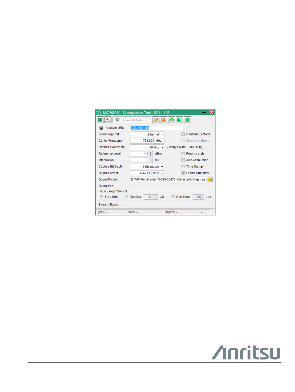
Settings Panel
The settings panel provides a variety of settings for the interface to the analyzer as well as some basic
measurement setup parameters.
Figure 3-3. Settings Panel
Status LED and Analyzer URL
This field is used to enter the analyzer URL or IP address. The indicator to the left will illuminate as described
below:
•Green LED: A connection has been established with the analyzer and the required option is installed.
The "Stream IQ Data” button will be enabled.
•Gray LED: No connection to the analyzer has been attempted.
•Red LED: No analyzer is found or an analyzer is found missing option 125 or 127. Streaming is
disabled.
Click the indicator or the Information button in the toolbar to display a status message dialog.
Streaming Port
Use this drop-down selection for Ethernet or PCIe data streaming. PCIe is only shown if a compatible analyzer
and PCIe hardware is detected.
Continuous Mode
Disabled if in Free Run mode (see below). If checked, then IQ data will continue until stopped. Each time the
target file size or collection size is met, a new file will be created. The IQ stream will not be continuous across
files and there will be a gap.
Stop on Errors
Enabled for PCIe only. The PCIe interface can detect if a byte is wrong. This setting is on by default. Uncheck
to continue streaming data even if a transfer error is detected.
Center Frequency
This field sets the analyzer’s center frequency. The setting takes affect when the Stream IQ Data is clicked.
3-4 PN: 10580-00476 Rev. A MA25101A UG

Software Operation and Overview 3-3 GUI Overview
Capture Bandwidth
This field sets the analyzer’s streaming bandwidth. The list of allowed streaming bandwidths is adjusted to
match the specific analyzer option. The setting takes affect when the Stream IQ Data is clicked.
Reference Level
This field sets the analyzer’s reference level. The setting takes affect when the Stream IQ Data is clicked.
Attenuation, Auto-Attenuation, and Preamp State
This field sets the analyzer’s attenuation level manually or to AUTO ATTEN, and sets the PRE AMP state.
The settings take affect when the Stream IQ Data is clicked.
Capture Bit Depth and Time Stamp
This field sets the analyzer’s streaming bit depth and toggles time stamps in the saved data file. The list of
allowed streaming bit depths is adjusted to match the specific analyzer option. The settings take affect when
the Stream IQ Data is clicked.
Output Format
This field sets the streamed data file and accompanying metadata file formats:
• Raw IQ (DGZ): This is the native format of the Anritsu SPA. For bit-depths < 32 bits, the I and Q values
are ordered in a proprietary way, and programs not specifically designed to support our DGZ files will
not be able to read these. Metadata is stored in an accompanying .dgzm file.
• Binary IQ (biq): This format undoes the I/Q pair ordering of Anritsu’s proprietary format. I/Q values are
written to the file in consecutive pairs. This file format is more easily read by 3rd party software. For
32-bit files, there is no difference. Metadata is written to an xml file.
Output Folder
This field sets the streamed data file and accompanying metadata file location where each filename is the time
stamp of the data stream. Network and external drives are not recommended.
Create Subfolder
If checked, a time stamped folder is created each time a new transfer is started. This is most useful if
Continuous Mode is on as then all related files are stored in a common location.
Output File
This is a display-only field of the current data transfer file name.
Run Length Control
Free Run: Streaming will continue until:
• The user presses “Stop”
• Out of space (transfer stops with about 2 GB remaining)
• An error is detected (If Stop on Errors is checked)
File Size: Streaming will continue until:
• The user presses “Stop”
• Out of space (transfer stops with about 2 GB remaining)
• An error is detected (If Stop on Errors is checked)
• The current file reaches the set file size and Continuous Mode is Off
• Continuous Mode is set to Off; the stream will end when the current file size limit is reached
MA25101A UG PN: 10580-00476 Rev. A 3-5

3-3 GUI Overview Software Operation and Overview
Run Time: Streaming will continue until:
• The user presses “Stop”
• Out of space (transfer stops with about 2 GB remaining)
• An error is detected (If Stop on Errors is checked)
• The current stream time reaches the set time and Continuous Mode is Off
• Continuous Mode is set to Off; the stream will end when current file elapsed time reaches the set time
Status Information
At the bottom of the window there is status information. Stream status indicates if a stream is active or if the
stream stops because of an error. The four boxes in the status bar show: total bytes downloaded (reset for each
file in Continuous Mode), transfer rate, elapsed time, available disk space.
Figure 3-4. Status Information
3-6 PN: 10580-00476 Rev. A MA25101A UG

Software Operation and Overview 3-4 Benchmark and Optimize
3-4 Benchmark and Optimize
Figure 3-5, “Transfer Optimization Dialog” is displayed when benchmark and optimize transfer parameters
button is pressed from the top toolbar.
Figure 3-5. Transfer Optimization Dialog
The top section of this dialog shows system parameters and available resources. The three items on top right
will have green or red indicators depending on system settings. If the PCIe status is not green, then not all
performance tests will run, specifically the capture bandwidth tests. Best performance occurs when the system
isn’t busy with other tasks, indicated by the CPU Utilization.
Available Drives
This list will vary depending on the number of disk drives on the system. Only fixed drives should be used and,
if multiple drives are shown, then those that you want to test can be selected with the checkboxes to the left.
Capture Bandwidth
Shows the bandwidths that will be successful at gapless streaming for 16-bit and 32-bit captures. Note that
this is a measurement of the system at a point in time. If for some reason the system load is different when
actually transferring data, performance will be different.
Performance Test
Evaluates system performance. This will give the user a good idea of what they can expect when running an IQ
Stream. Note that for streaming data at relatively low bandwidth, such as anything below 50 MHz, much of
this discussion is irrelevant. To obtain the highest possible transfer rates, careful tuning may be required.
Blue Links
The blue links along the bottom are for controlling system services. Only the right-most link (Manage Services)
will be enabled unless the program is started with Administer privileges. Most services will not have a drastic
effect on IQ streaming, but cumulatively they may have a significant effect. IQ Acquisition Tool will stop the IQ
stream if a single byte is incorrect, even if it is 1 out of 10 billion. Services may periodically wake and request
access to system resources, causing the IQ stream to be momentarily interrupted. To avoid this, it is useful to
stop as many services as possible without making the PC unstable.
Stop ## Common Services
Stops services from a common list of safe services to stop. Stopping these services is safe assuming the PC is
dedicated to PCIe data transfer. If they are doing other tasks, an expected service may be missing. A PC is
likely to restart some services that it needs, so even after stopping them the count in the link text will likely
not go to ‘0’. Stopping Services with this function is temporary. All services will restart when the PC is
restarted.
MA25101A UG PN: 10580-00476 Rev. A 3-7

3-4 Benchmark and Optimize Software Operation and Overview
Stop Custom Services
This will apply a list of services to stop. The list creation is the next link. Many PC’s will have varied set of
services running. Different virus protection software, for instance. The standard list will not include these.
Save Custom Service List
This creates a list, based on the current PC status, of services that have been stopped. This is most useful if the
user has used the ‘Manage Services’ link to stop services that are not included in the Common Services list.
Restore Services
This will restart all services that have been stopped. This is a way to restore the PC operation after IQ
streaming is complete.
Manage Services
This opens the standard Windows Services control panel application. This allows the user to select specific
services to stop, and also allows the user to permanently stop services of their choosing.
3-8 PN: 10580-00476 Rev. A MA25101A UG

Software Operation and Overview 3-5 Command-Line Interface
3-5 Command-Line Interface
If your use case requires controlling the IQ stream through another software package, or if you want to script
the data transfer, the command-line interface is very convenient.
To run the command-line interface, open a console window to the application folder (typically C:\Program
Files\Anritsu Company\IQ Acquisition Tool). You can easily open a console window by browsing to the
application folder using Windows File Explorer, then entering ‘cmd’ in the address bar.
Note
The command-line application is named ‘IQConsole.exe’. All options and settings are entered with this
application as command-line directives. Some directives can be entered together on a single command-line, and
some need to be entered singly. All commands begin with a hyphen (-). Many commands take an argument,
and a colon separates the directive from its argument.
As an example for format, consider the directive to set the ip address (analyzer hostname).
Iqconsole –h:192.168.0.22
The ‘-h’ tells the application that we are setting the hostname. The colon separates the directive from the value
passed in, and the hostname follows.
As another example, we can set the output filename:
Iqconsole –n:C:\datafiles\Data.bin
The ‘-n’ tells the application we are setting the output filename. The color separations the directive from the
filename, and the filename follows. Please note, the default value is ‘Data.bin’. The default value does not
contain a path specifier, so the file will be written to the current folder. If you are running from the application
folder, this is write protected and the transfer will fail. Specify a folder that you have write privileges to.
In the descriptions below, angle brackets (‘< >’) represent input values. Do not include the angle brackets, and
replace the text between the brackets with the desired value. A vertical bar (‘|’) should be read as ‘or’. Include
a single value from the list separated by vertical bars.
For convenience, certain common directives can be shortened to a single letter:
-s for stream
-a for abort
-d for display
-m for metadata
Use any combination of the following command-line directives to configure and control the spectrum analyzer.
These can be used together on a single line.
Note: if you want to use the command-line interface to stop services that might interfere with data
transfer, you will need to open the console window in Administrator mode
-h:<Hostname> => IP address or hostname of the spectrum analyzer.
-f:<Frequency> => The center frequency in MHz.
-b:<BW> => The capture bandwidth in MHz.
-r:<RefLevel> => The reference level in dBm.
-a:<Attenuation> => The attenuation in dBm (Use 'Auto' to set auto-attenuation).
-d:<8|16|I32|F32> => The bit-depth.
-p:<on|off> => Turn preamp on or off.
-c:<count> => The number of 4 MB packets to transfer in I/Q stream.
-e:<yes|no> => Indicates if data capture should continue if an error in the data stream is detected.
-n:<filename> => Set the output filename (Default: 'Data.bin'.)
All of the above settings are remembered and do not need to be re-entered, except to change settings.
MA25101A UG PN: 10580-00476 Rev. A 3-9

3-5 Command-Line Interface Software Operation and Overview
The following commands should be used singly. Other commands will be ignored.
-? or –help => Display a summary list of all command directives.
-pcie Set output port to PCIe
-Ethernet Set output port to Ethernet
-stream => Start streaming I/Q data.
-metadata => Create metadata file (.dgzm) for most recent capture. (May be invalid if not done
promptly)
-abort => Abort IQ streaming.
-display => Display all saved parameter values.
-info => Display PCIe interface summary information.
-kill => Stop many common Windows processes that might interfere with data throughput.
-scpi:<cmd> => Pass through any supported SCPI command to the analyzer.
-reset => Reset the spectrum analyzer to factory default settings.
-restart => Reboot the spectrum analyzer.
The following commands are for testing the interface. If source is set to ‘test’ then a test pattern is returned.
You can use the –t directive to set the transfer rate of the test pattern (for instance, to test at 50 MHz, use
‘-t:50’)
-s:<source> => Source is either 'iq' or 'test'.
-t:<rate> => The transfer rate when using test ramp data.
-wt => Perform disk write test to verify disk performance is adequate for IQ stream.
-verify => Perform verification of all file formats.
When streaming over Ethernet, the transfer is accomplished by a series of network packets. As the size of
these packets are not controlled, the application has no control over the size of the transfer. The transfer will
stop when the time or size requirement is met. However, the actual time and file size may be much longer or
larger than anticipated depending on the size and transfer time of the last packet.
3-10 PN: 10580-00476 Rev. A MA25101A UG


Anritsu utilizes recycled paper and environmentally conscious inks and toner.
Anritsu Company
Morgan Hill, CA 95037-2809
490 Jarvis Drive
USA
http://www.anritsu.com
 Loading...