

Page 1
50 High Frequency Electronics
High Frequency Design
HIGH-Q RESONATORS
C
eramic coaxial resonators have
become an everyday sight in
engineering development laboratories and manufacturing production lines. These components use the
size-reducing effects of high diectric
constant ceramic materials to make
the smallest possible resonators for
VCOs and filters operating from VHF
to microwave frequencies.
Figure 1 shows the typical construction of a commercially available
ceramic resonator. The configuration
is coaxial, with an approximately
square cross-section outer conductor
and a round (cylindrical) center conductor. Physical dimensions for a particular coaxial element are W, d and
l. Together with the dielectric constant of the ceramic material, ε
r
, the
approximate coaxial line characteristic impedance can be calculated by:
Commonly-used products typically
have Z
0
in the range of 5 to 15 ohms.
The electrical length of a coaxial
line is affected by ε
r
as follows:
Since the ceramics used in these
coaxial elements have ε
r
from 10 to
more than 100, so we can see from
the above equation that the electrical
length can be reduced by a factor of
ten or more from the free space
length. For example, a 300 MHz 1/4wavelength line section with ε
r
of 90
has a length of 1.037 in. (26.3 mm),
compared to a free space length of
9.84 in. (250 mm).
The typical resonator consists of a
shorted λ/4 line section, although an
open-circuit λ/2 line may be used for
some applications. Typically, a ceramic coaxial element can be obtained in
a specified length, with one end plated to “short-circuit” the center conductor to the outer conductor.
Resonator Q can vary significantly with different materials, frequencies and size, but will have a value in
the hundreds (~150 to 500).
Tuning the Resonator
For VCO applications the resonator must be tuned over a significant frequency range. The simplest
method for doing this is to select a
coaxial element with a self-resonant
frequency (SRF) that is 20 to 30 percent higher than the operating frequency, where it will present an
inductive reactance. Parallel capacitance (e.g. a varactor tuning diode)
can then be added to obtain resonance at the desired frequency.
The inductive reactance of a coaxial line can be approximated using:
where Z
0
is the characteristic
impedance of the line, and Θ is its
electrical length in radians. (Θ =
2πl/λ
eff
, where λ
eff
is the wavelength
in the dielectric at the operating frequency.)
This value of inductance (actually,
a range of values, since it varies with
frequency), can be used to design the
desired VCO circuit.
Tuning of resonators for filters
does not necessarily mean production
line tweaking. Often, resonators are
tuned with fixed capacitors to compensate for the shift in resonance due
to different coupling coefficients
between filter sections. This enables
a single resonator type to be used in
a typical “stagger-tuned” filter.
Cautions and Caveats
There are physical limitations in
the ceramic resonator manufacturing
processes. Each manufacturer will
have a recommended range of SRF
for each product, which is governed
by practical lengths for each crosssection profile. Consult with the supplier if you want a resonator at the
limits of the recommended sizes.
High reactance values can be
obtained close to resonance. If such
use is considered, examine such factors as temperature stability (of the
resonator and the surrounding circuitry) and manufacturing tolerances
from piece-to-piece and lot-to-lot.
Finally, remember all the stray
and parasitic reactances and resistances: the effect of plating on the
shorted end, the inductance of the
inner conductor connecting tab, and
the effects due to the PC board
mounting method and proximity to
adjacent components.
()
Basic Data on High-Q
Ceramic Coaxial Resonators
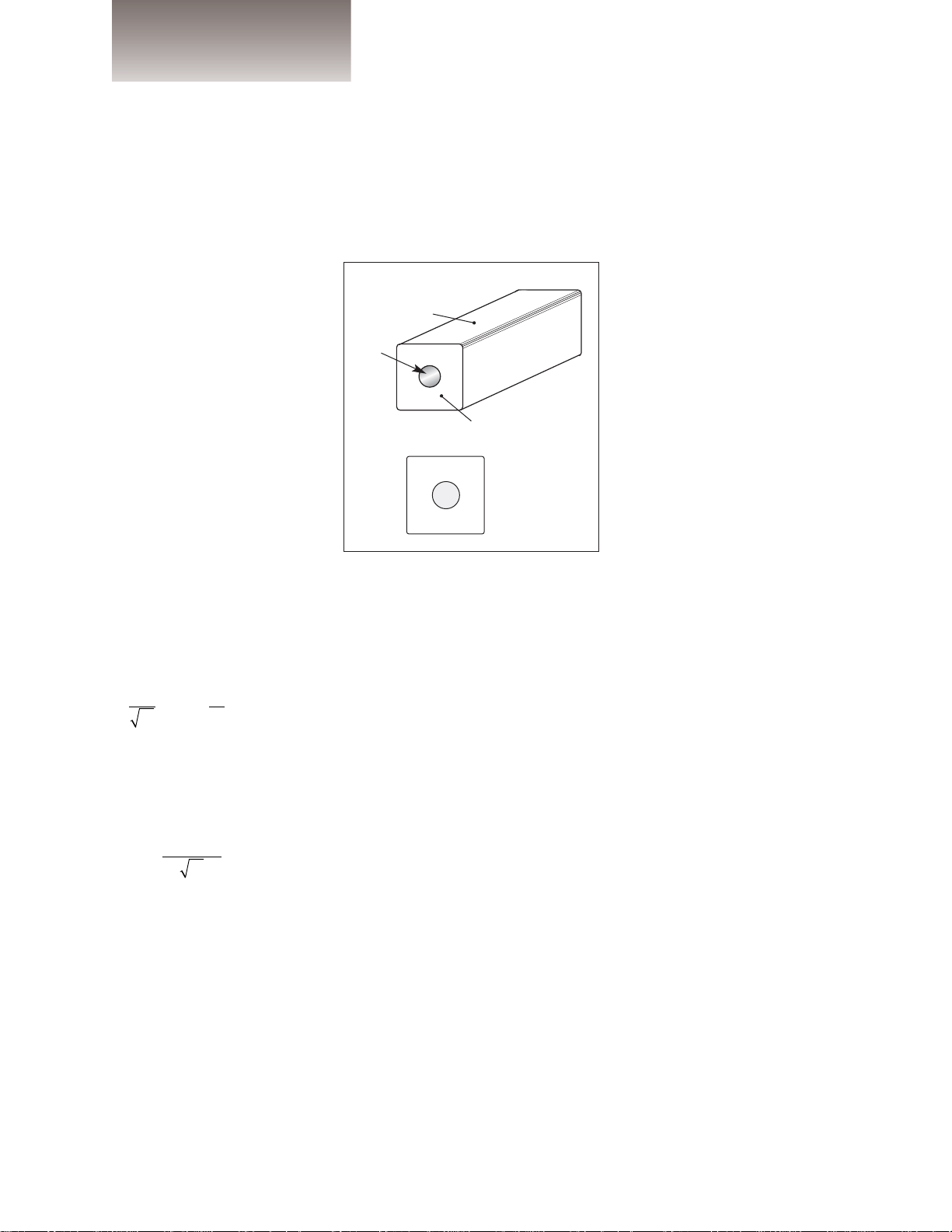
Conductors silver-plated on
ceramic body:
Outer
Inner
(hollow)
Ceramic dielectric
Figure 1 · Construction of a ceramic coaxial resonator and its physical dimensions.
W d l = length
From November 2002 High Frequency Electronics
Copyright © 2002, Summit Technical Media, LLC
108=
λ
freespace
ε
W
d
r
60
Z
0
λ
effective
ln .
ε
r
=
XZ
=
tan Θ
L
0
 Loading...