

46 High Frequency Electronics
High Frequency Design
RF POWER AMPLIFIERS
RF and Microwave Power
Amplifier and Transmitter
Technologies —
Part 5
By Frederick H. Raab, Peter Asbeck, Steve Cripps, Peter B. Kenington,
Zoya B. Popovich, Nick Pothecary, John F. Sevic and Nathan O. Sokal
The ever-increasing
demands for more bandwidth, coupled with
requirements for both
high linearity and high
efficiency create everincreasing challenges in
the design of power
amplifiers and transmitters. A single W-CDMA
signal, for example, taxes the capabilities of a
Kahn-technique transmitter with a conventional class-S modulator. More acute are the
problems in base-station and satellite transmitters, where multiple carriers must be
amplified simultaneously, resulting in peakto-average ratios of 10 to 13 dB and bandwidths of 30 to 100 MHz.
A number of the previously discussed techniques can be applied to this problem, including
the Kahn EER with class-G modulator or splitband modulator, Chireix outphasing, and
Doherty. This section presents some emerging
technologies that may be applied to wideband,
high efficiency amplification in the near future.
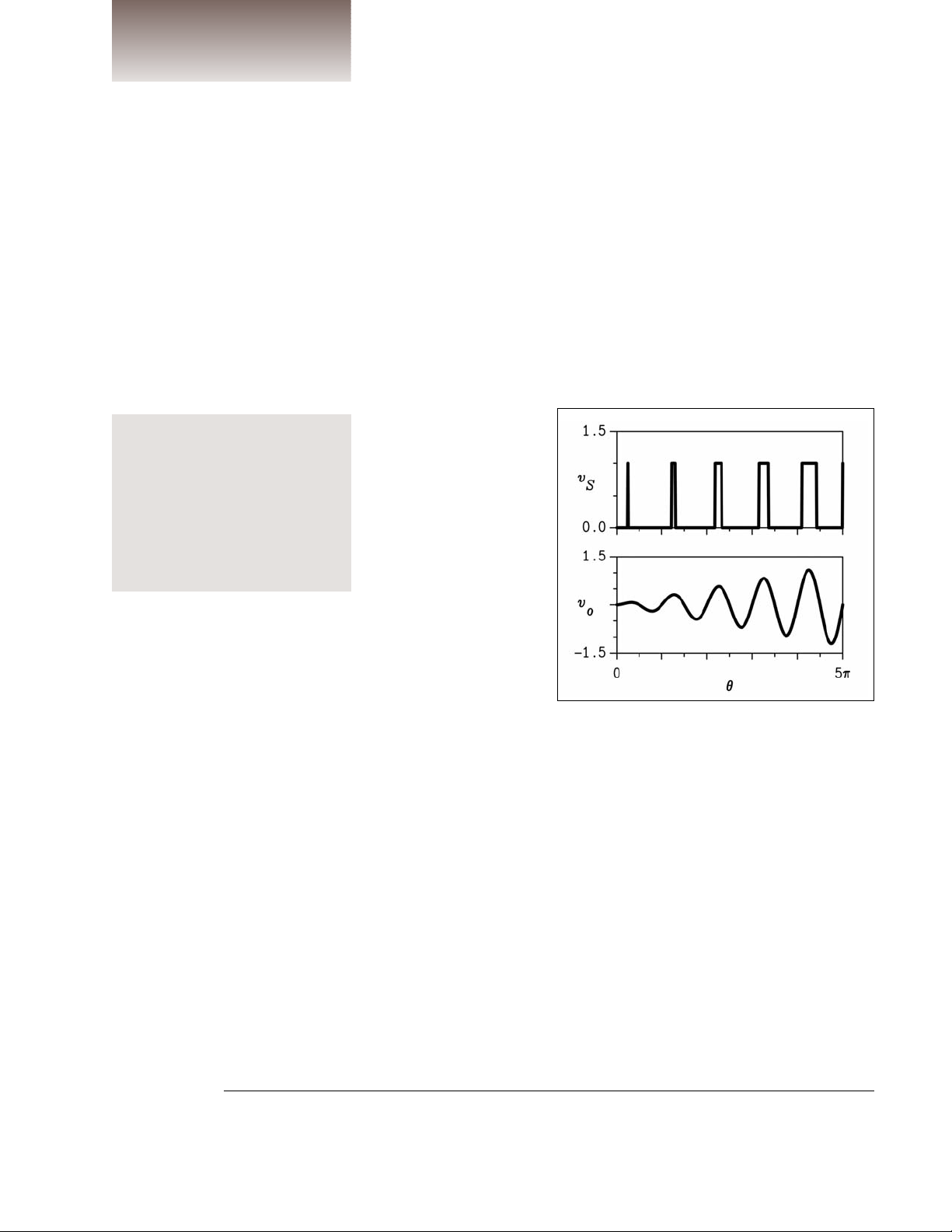
RF Pulse-Width Modulation
Variation of the duty ratio (pulse width) of
a class-D RF PA [112] produces an amplitudemodulated carrier (Figure 59). The output
envelope is proportional to the sine of the
pulse width, hence the pulse width is varied in
proportion to the inverse sine of the desired
envelope. This can be accomplished in DSP, or
by comparison of the desired envelope to a
full-wave rectified sinusoid. The pulse timing
conveys signal phase information as in the
Kahn and other techniques.
Radio-frequency pulse-width modulation
(RF PWM) eliminates the series-pass losses
associated with the class-S modulator in a
Kahn-technique transmitter. More importantly, the spurious products associated with
PWM are located in the vicinity of the harmonics of the carrier [113] and therefore easily removed. Consequently, RF PWM can
accommodate a significant RF bandwidth
with only a simple, low-loss output filter.
Ideally, the efficiency is 100 percent. In
practice, switching losses are increased over
those in a class-D PA with a 50:50 duty ratio
because drain current is nonzero during
switching.
Emerging techniques are
examined in this final
installment of our series on
power amplifier technolo-
gies, providing notes on
new modulation methods
and improvements in
linearity and efficiency
This series of articles is an expanded version of the paper, “Power Amplifiers and Transmitters for RF and
Microwave” by the same authors, which appeared in the the 50th anniversary issue of the IEEE Transactions on
Microwave Theory and Techniques, March 2002. © 2002 IEEE. Reprinted with permission.
Figure 59 · RF pulse-width modulation.
From January 2004 High Frequency Electronics
Copyright © Summit Technical Media, LLC
48 High Frequency Electronics
High Frequency Design
RF POWER AMPLIFIERS
Previous applications of RF PWM have been limited to
LF and MF transmitters (e.g., GWEN [114]). However, the
recent development of class-D PAs for UHF and
microwave frequencies (Figure 60) offers some interesting
possibilities.
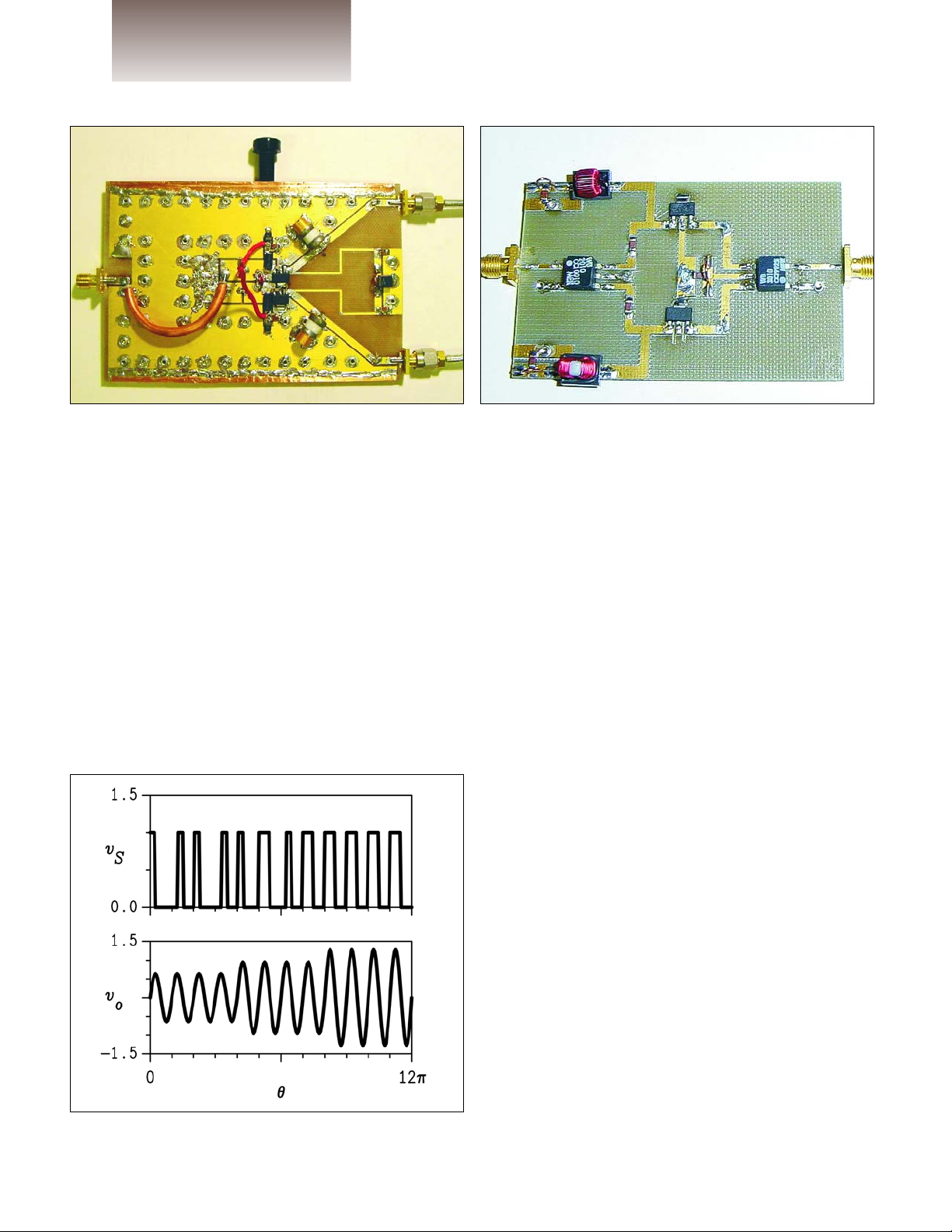
Delta-Sigma Modulation
Delta-sigma modulation is an alternative technique
for directly modulating the carrier produced by a class-D
RF PA (Figure 61) [PA8],[PA9]. In contrast to the basically analog operation of RF PWM, delta-sigma modulation
drives the class-D PA at a fixed clock rate (hence fixed
pulse width) that is generally higher than the carrier frequency (Figure 62). The polarity of the drive is toggled as
necessary to create the desired output envelope from the
average of the cycles in the PA. Phase is again conveyed
in pulse timing.
The delta-sigma modulator employs an algorithm
such as that shown in Figure 63. The signal is digitized by
a quantizer (typically a single-bit comparator) whose output is subtracted from the input signal through a digital
feedback loop, which acts as a band-pass filter. Basically,
the output signal in the pass band is forced to track the
desired input signal. The quantizing noise (associated
with the averaging process necessary to obtain the
desired instantaneous output amplitude) is forced outside
of the pass band.
The degree of suppression of the quantization noise
depends on the oversampling ratio; i.e., the ratio of the
digital clock frequency to the RF bandwidth and is relatively independent of the RF center frequency. An example of the resultant spectrum for a single 900-MHz carrier and 3.6-GHz clock is shown in Figure 64. The quantization noise is reduced over a bandwidth of 50 MHz,
which is sufficient for the entire cellular band. Out-ofband noise increases gradually and must be removed by a
band-pass filter with sufficiently steep skirts.
As with RF PWM, the efficiency of a practical deltasigma modulated class-D PA is reduced by switching losses associated with nonzero current at the times of switching. The narrow-band output filter may also introduce
significant loss.
Carrier Pulse-Width Modulation
Carrier pulse-width modulation was first used in a
UHF rescue radio at Cincinnati Electronics in the early
1970s. Basically, pulse-width modulation as in a class-S
modulator gates the RF drive (hence RF drain current) on
and off in bursts, as shown in Figure 65. The width of each
burst is proportional to the instantaneous envelope of the
Figure 60 · Current-switching PA for 1 GHz (courtesy
UCSD).
Figure 61 · Prototype class-D PA for delta-sigma modulation (courtesy UCSD).
Figure 62 · Delta-sigma modulation.
 Loading...