


606B.3XX
1
© 2016 AS America Inc.
Installation Instructions
Certied to comply with ASME A112.19.2
© 2016 AS America, Inc.
NOTE TO INSTALLER: Please give this manual to the customer after installation.
To learn more about American Standard Selectronic
®
Products visit our website at: www.americanstandard-us.com
or e-mail us at: CRTTEAM@americanstandard.com
For Parts, Service, Warranty or other Assistance,
please call (844) CRT-TEAM / (844) 278-8326 (In Canada: 1-800-387-0369)
(In Toronto Area only: 1-905-306-1093)
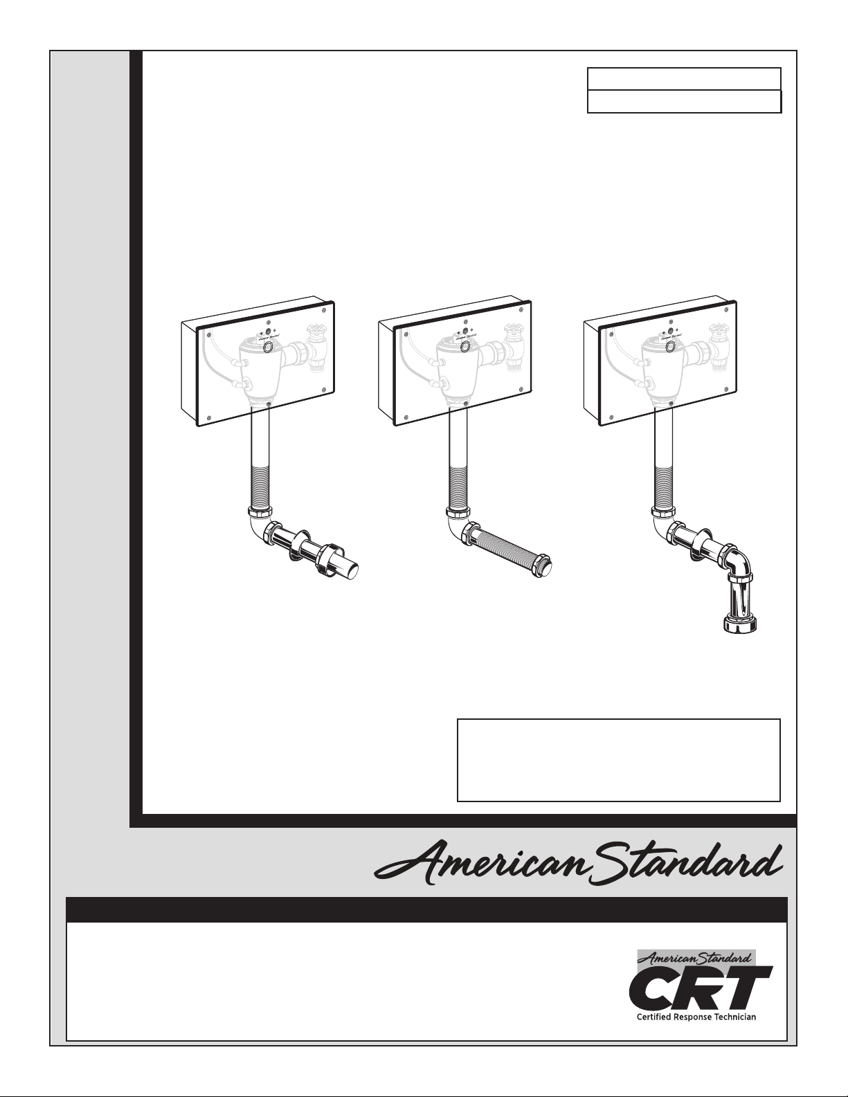
SELECTRONIC
®
CONCEALED TOILET FLUSH VALVE
1.1, 1.28 & 1.6 GPF
MODEL NUMBERS
606B.3XX
CAUTION: Use only American Standard supplied
transformers and cable sets. Using non-AS supplied
cables, or cutting, splicing or modifying any components
will void the warranty.
M965642 Rev. 1.5 (11/16)
Concealed Back SpudExposed Back Spud Top Spud
2
Thank you for selecting American-Standard...the benchmark of ne quality for over 100 years. To ensure that your
installation proceeds smoothly--please read these instructions carefully before you begin.
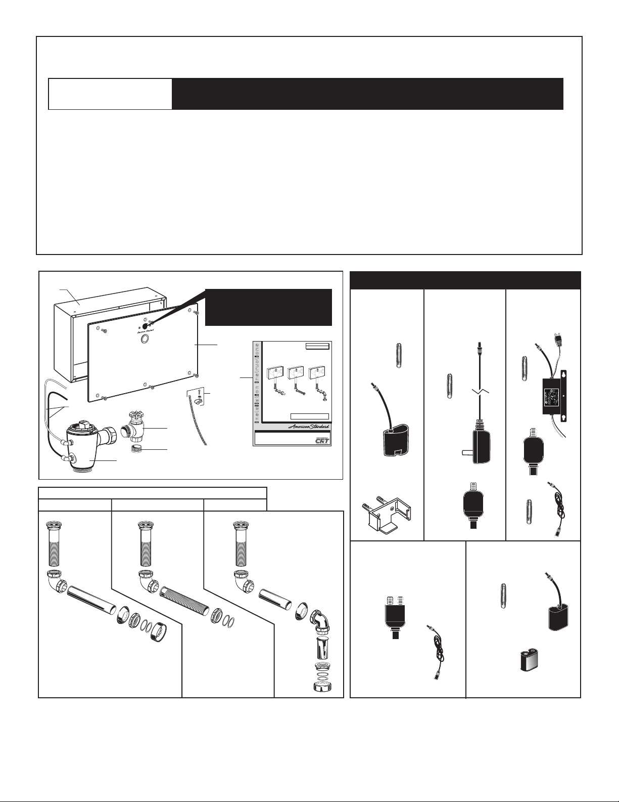
Remove the Flush Valve items from the carton. The illustration below shows all items after they have been
removed from the carton. Some items may be packaged partially assembled to other items.
UNPACKING
All American Standard Products Are Water Tested At Our Factory.
Some Residual Water May Remain In The Valve During Shipping.
1. Installation Instructions
2. Flush Valve Body Assembly
3. Cover Plate with Sensor
4. Wall Box
5. Sweat Adapter
6. Stop Valve
7. Manual Override Hoses
8a. Vacuum Breaker Flush Connection
(Exposed Back Spud)
8b. Vacuum Breaker Flush Connection
(Concealed Back Spud)
8c. Vacuum Breaker Flush Connection
(Top Soud)
9. Safety Chain
3
8c8b8a
6065.XXX 6067.XXX
VACUUM BREAKER FLUSH CONNECTIONS
6068.XXX
4
1
9
6
5
2
7
DO NOT REMOVE PROTECTIVE
FILM FROM SENSOR
EYE UNTIL INSTALLATION
IS COMPLETE.
Installation Instructions
Certified to comply with ASME A112.19.2
© 2016 AS America, Inc.
CAUTION: Use only American Standard supplied cable
sets. Using non-AS supplied cables, or cutting, splicing or
modifying any components will void the warranty.
Concealed Back SpudExposed Back Spud Top Spud
SELECTRONIC™CONCEALED
TOILET FLUSH VALVE
1.28 & 1.6 GPF
NOTE TO INSTALLER: Please give this manual to the customer after installation.NOTE TO INSTALLER: Please give this manual to the customer after installation.
To learn more about American Standard Selectronic
®
Products visit our website at: www.americanstandard-us.com
or e-mail us at: CRTTEAM@americanstandard.com
For Parts, Service, Warranty or other Assistance,
please call (844) CRT-TEAM / (844) 278-8326 (In Canada: 1-800-387-0369)
(In Toronto Area only: 1-905-306-1093)
POWER KITS — SOLD SEPARATELY
Plug-In AC
Power Kit
Hard-Wired AC
Power Kit
Multi-AC
Power Kit
PWRX
Power Kit
PK00. PACPK00.WRK
PK00.HAC
PK00.MAC
CR-P2 Battery
Power Kit
MODEL NUMBERS
606B.3XX
M965642 Rev. 1.5 (11/16)
3
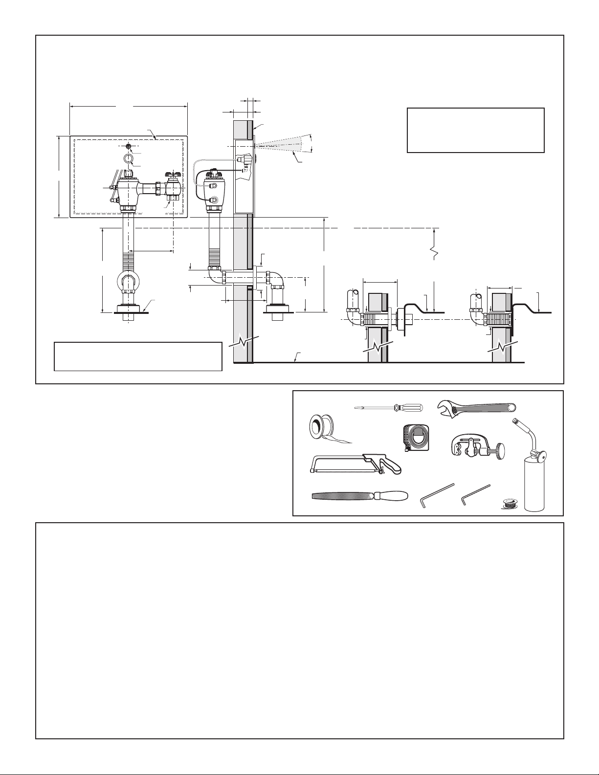
-C-L-
51 mm
(2")
404 mm
(15-7/8")
389 x 265 mm
(15-5/16" x 10-3/8")
ROUGH OPENING FOR BOX
OVERRIDE
BUTTON
280 mm
(11 ")
176 mm MAX.
(6-15/16") MAX.
TOP OF
FIXTURE
FINISHED WALL
SENSOR
108 -134 mm
(4-1/4" to 5-1/4")
*Note: The Critical Line (-C-L-) on Vacuum
Breaker must typically be 6
" (152 mm) min.
above fixture. Consult Codes for details.
-C-L-
*
15˚
SUPPLY
(1") NPT
152 mm
(6") MIN.
240 mm MAX.
(9-1/2") MAX.
-C-L-
128 mm MAX.
(5") MAX.
FOR LOCATION OF INLET SUPPLY ON BACK INLET
FIXTURES AND CORRECT HEIGHT FROM FINISHED FLOOR,
REFER TO FIXTURE INSTRUCTION SHEET.
CONCEALED BACK
SPUD TOILET
EXPOSED BACK
SPUD TOILET
TOP OF
FIXTURE
FINISHED
FLOOR
51 mm
(2)
51 mm
(2")
TOP OF
FIXTURE
450 mm MAX.
(17-3/4") MAX.
400 mm MAX.
(15-3/4") MAX.
25 mm (1") MAX.
WALL THICKNESS
70 mm
(2-3/4") DIA.
TOP SPUD
TOILET
DETECTION ZONE
400 -800 mm
(Factory Setting: 400 mm)
152 mm MIN.
(6") MIN.
*-C-L-
Fig. 1
Roughing-in
Dimensions
RECOMMENDED TOOLS; Fig. 2.
1. Teon Tape
2. Flat Blade Screwdriver
3. Adjustable Wrench
4. Tape Measure
5. Hacksaw
6. Tubing Cutter
7. File
8. For Sweat Connection; Solder and Torch
9. 2.5 mm Hex Wrench
10. 1.5 mm Hex Wrench
GENERAL DESCRIPTION:
SELECTRONIC
®
PROXIMITY TOILET
FLUSH VALVE
Concealed Flushometer for 1-1/2"
Top Spud Fixtures
PRIOR TO INSTALLATION
Note: Prior to installing the Selectronic™Flush
Valve the following items must be installed.
1. Toilet
2. Drain line
3. Water supply line
IMPORTANT:
• All plumbing and electrical wiring should be
installed in accordance with applicable codes
and regulations.
• The use of water hammer arrestors is strongly
recommended for commercial applications. All piping
behind the walls should be properly secured and
fastened.
• Wate r supply lines must be sized to provide an
adequate volume of water for each xture.
• Flush all water lines prior to operation (see Step 3).
Dirt and debris can cause ush valve to run continuously.
• With the exception of Stop Valve Inlet, DO NOT
use pipe sealant or plumbing grease on any
valve component or coupling!
• Protect the chrome or special nish on the Flushometer.
DO NOT USE toothed tools on nished surfaces to install
or service these valves. Also see “Care and Cleaning”
section of this manual.
• This product contains mechanical and/or electrical
components that are subject to normal wear. These
components should be checked on a regular basis and
replaced as needed to maintain the valve’s performance.
Fig. 2
1
2
3
4
5
6
7 9 10
8
10'
M965642 Rev. 1.5 (11/16)
CAUTION: Use only American Standard
supplied transformers and cable sets.
Using non-AS supplied cables, or cutting,
splicing or modifying any components will
void the warranty.

4
1
INSTALL WALL BOX; Fig. 3
1. Frame out a 389 mm x 265 mm (15-5/4" X 10-3/8") rough
opening in wall for the WALL BOX (1) at the dimension
shown.
2. Fasten one end of the SAFETY CHAIN (2) and CLIP
(4) to the WALL BOX (1) with NUT & SCREW (3) provided.
3. Install the WALL BOX (1) into rough opening in the wall
Level and secure the WALL BOX (1) to the wall opening
with screws.
Important: Front face of WALL BOX (1) should be ush
with nished wall.
4. Cut a 2" hole for outlet pipe at dimension shown.*
2
INSTALL SWEAT ADAPTER; Fig. 4
Note: Stop Valve inlet is 1" NPT. For optional sweat
connection, install Sweat Adapter (1) (Supplied) for 1"
copper pipe supply line.
1. Clean the end of the supply pipe. Push the threaded
SWEAT ADAPTER (1) until it is seated against the
internal stop. Sweat the ADAPTER (1) to the pipe.
2. Install the STOP VALVE (2) to the water supply line
with the outlet positioned as required (Behind the Wall).
3. Support piping as required.
3
FLUSH OUT SUPPLY LINES; Fig. 5
1. Open STOP VALVE (1).
2. Tur n on water supply line to ush line of any debris or
sediment.
3. Close STOP VALVE (1) and turn off water supply line.
CAUTION
Turn water supplies off before
beginning
M965642 Rev. 1.5 (11/16)
1
ROUGH OPENING IN WALL
265 mm
(10-3/8")
389 mm
(15-5/16")
LEVEL
3
2
4
Fig. 3 (TOP SPUD FIXTURE ILLUSTRATED)
*FOR HOLE LOCATION OF
SUPPLY ON BACK INLET
FIXTURES, REFER TO FIXTURE
BEING INSTALLED FOR CORRECT
HEIGHT FROM FINISHED FLOOR
128 mm MAX.
(5") MAX.
176 mm MAX.
(6-15/16") MAX.
Fig. 4
2
1
FILE
EDGES
CLEAN & SOLDER
TO ADAPTER (1)
115 mm-134 mm
(4-1/2" TO 5-1/4")
STOP VALVE
(1"NPT)
STOP VALVE OUTLET
Fig. 5
1
CLOCKWISE CLOSES
STOP VALVE
COUNTER-CLOCKWISE
OPENS STOP VALVE
FLUSH VALVE INSTALLATION

5
M965642 Rev. 1.5 (11/16)
4
INSTALL VACUUM BREAKER AND
FLUSH CONNECTIONS; Fig. 6
1. Place the SPUD FLANGE (1) over the spud on the Fixture. Fig. 6.
2. Place FRICTION WASHER (3) and SEAL WASHER (4) inside
SPUD COUPLING NUT (2) and thread onto Spud. Do not tighten
fully. Fig. 6.
3. Remove the ELBOW COUPLING NUTS (6, 6a) from the CHROME
ELBOW (5). Make sure you have a TAPERED RUBBER WASHER
(7), PLASTIC SUPPORT (8) and SQUARE SEAL WASHER (9).
Fig. 6a.
4. Install the SQUARE SEAL WASHER (9) onto the PLASTIC
SUPPORT (8) if not already installed. Insert the PLASTIC
SUPPORT (8) into the VERTICAL OUTLET PIPE (10). Slide the
ELBOW COUPLING NUT (6) onto the VERTICAL OUTLET PIPE
(10). Connect the ELBOW COUPLING NUT (6) to the CHROME
ELBOW (5) and tighten fully.
5. Insert the VERTICAL OUTLET PIPE (10) with assembled CHROME
ELBOW (5) into the SPUD COUPLING NUT (2) and push it down.
Do not tighten fully. Fig. 6a.
Note: Cutting the VERTICAL OUTLET PIPE (10) may be necessary
for the CHROME ELBOW (5) center line to line up with opening in
the wall.
6. Measure and cut the HORIZONTAL OUTLET PIPE (11) to length
required. Fig. 6b.
Important: Make sure that there is a minimum of 1-1/4" for
engagement with elbow when making your measurement.
7. Remove the ELBOW COUPLING NUT (14) from BRASS ELBOW
(12) and slide it onto the HORIZONTAL OUTLET PIPE (11). Install
the SQUARE SEAL WASHER (13) onto the PLASTIC SUPPORT
(15) if not already installed. Insert the PLASTIC SUPPORT (15) into
the HORIZONTAL OUTLET PIPE (11). Connect the ELBOW
COUPLING NUT (14) to the BRASS ELBOW (12) and tighten fully.
Fig. 6b.
8. From behind the wall, insert the assembled BRASS ELBOW and
HORIZONTAL OUTLET PIPE (12, 11) through the hole in the wall.
Install WALL ESCUTCHEON (16) onto the HORIZONTAL OUTLET
PIPE (11). Slide the ELBOW COUPLING NUT (6a) and TAPERED
RUBBER WASHER (7) onto the HORIZONTAL OUTLET PIPE (11).
Push the HORIZONTAL OUTLET PIPE (11) into the CHROME
ELBOW (5). Tighten ELBOW COUPLING NUT (6a) but not fully.
Fig. 6b.
9. For back spud installations: Follow steps #1 and #2 to install the
spud coupling kit. Push the HORIZONTAL OUTLET PIPE (11) into
the spud connection on the back of the xture. Do not tighten fully.
If spud coupling kit is not required, install HORIZONTAL OUTLET
PIPE (11) into back spud on xture and hand tighten. Fig. 6b.
10. All installations: If required, cut scored VACUUM BREAKER PIPE
(17), leave a minimum of 1-1/4" (32 mm) of pipe to ensure
engagement with compression coupling. Assemble the ELBOW
COUPLING NUT (14a) and TAPERED RUBBER WASHER (19)
onto the VACUUM BREAKER PIPE (17). Install VACUUM
BREAKER PIPE (17) into BRASS ELBOW (12) and hand tighten
COUPLING NUT (14a). Fig. 6c.
Note: If cutting VACUUM BREAKER PIPE (17) to size, note that
Critical Line (C/L) on Vacuum Breaker must typically be 6"
(152mm) above xture. Consult Code for details.
Fig. 6
Fig. 6a
Fig. 6b
Fig. 6c
1
2
3
4
1-1/2" TOP SPUD
9
6a
8
7
5
6
10
FLANGE END UP
2
TAPERED SIDE
14
16
12
11
15
5
7
6a
13
FLANGE END
11
14a
19
19
17
TOP SPUD
INSTALLATION
BACK SPUD
INSTALLATION
BACK SPUD
INSTALLATION
TOP SPUD
INSTALLATION
TAPERED
SIDE
12
TAPERED SIDE UP
TAPERED
SIDE UP
 Loading...