


Installation Instructions
SELECTRONIC |
® |
|
606B.101 606B.051 606B.025 606B.013 |
||
|
MODEL NUMBERS |
|
EXPOSED URINAL FLUSH VALVE |
|
|
|
||
AC POWERED PROXIMITY |
|
|
0.125 0.25 0.5 & 1.0 GPF |
|
|
COVER PLATE
(Required for Front Installation Only)
Exposed Flushometer for 3/4" Top Spud Urinals
CAUTION: Use only American Standard supplied transformers and cable sets. Using non-AS supplied cables, or cutting, splicing or modifying any components will void the warranty.
Certified to comply with ASME A112.19.2
© 2017 AS America, Inc.
NOTE TO INSTALLER: Please give this manual to the customer after installation.
To learn more about American Standard Selectronic® Products visit our website at: www.americanstandard-us.com or e-mail us at: CRTTEAM@americanstandard.com
For Parts, Service, Warranty or other Assistance,
please call (844) CRT-TEAM / (844) 278-8326 (In Canada: 1-800-387-0369)
(In Toronto Area only: 1-905-306-1093)
© 2017 AS America Inc. |
1 |
M965645 EN REV. 1.7 (5/17) |

Thank you for selecting American-Standard...the benchmark of fine quality for over 100 years.To ensure that your installation proceeds smoothly--please read these instructions carefully before you begin.
UNPACKING |
All American Standard Products Are Water Tested At Our Factory. |
|
Some Residual Water May Remain In The Valve During Shipping. |
Remove the Flush Valve items from the carton. The illustration below shows all items after they have been removed from the carton. Some items may be packaged partially assembled to other items.
1. Installation Instructions |
8. |
Sweat Adapter |
2. Flush Valve Body Assembly |
9. |
Stop Valve |
3.Vacuum Breaker Tube
4.Spud Coupling Nut and Washers
5.Spud Flange
6.Wall Escutcheon
7.Cover Tube
CARE INSTRUCTIONS:
DO: CLEAN THE PRODUCT WITH CLEAR WATER, DRY WITH A SOFT COTTON FLANNEL CLOTH.
DO NOT: DO NOT CLEAN THE PRODUCT WITH SOAPS, ACID, POLISH, ABRASIVES, HARSH CLEANERS, OR A CLOTH WITH A COARSE SURFACE.
2
COVER PLATE
(Required For
Front Installation 3
Only)
4
DO NOT REMOVE PROTECTIVE FILM FROM SENSOR EYE UNTIL INSTALLATION IS COMPLETE.
7
6 |
8 |
|
9 |
||
|
1
Instructions |
SELECTRONIC |
® |
6061.101 6061.051 6061.025 |
6061.013 |
|
MODEL NUMBERS |
|
||
|
|
for 3/4"Top Spud Urinals |
|
|
|
EXPOSED URINAL FLUSH VALVE |
6062.101 6062.051 6062.025 |
6062.013 |
|
|
AC POWERED PROXIMITY |
|
|
|
|
0.125 0.25 0.5 & 1.0 GPF |
|
|
|
|
|
|
COVER PLATE |
|
|
|
|
(Required for Front Installation Only) |
|
Installation |
|
|
Exposed Flushometer |
|
|
|
CAUTION: Use only American Standard supplied |
|
|
|
|
|
transformers and cable sets. Using non-AS supplied |
|
|
|
|
cables, or cutting, splicing or modifying any components |
|
|
|
|
will void the warranty. |
|
|
© 2015 AS America, Inc. |
|
|
|
NOTE TO INSTALLER: Please give this manual to the customer after installation.
To learn more about American Standard Selectronic Products visit our website at: www.americanstandard-us.com or e-mail us at: CRTTEAM@americanstandard.com
For Parts, Service, Warranty or other Assistance,
please call (844) CRT-TEAM / (844) 278-8326 (In Canada: 1-800-387-0369) (In Toronto Area only: 1-905-306-1093)
POWER KIT - SOLD SEPARATELY
Hard-Wire AC |
|
Multi-AC |
||||||||||
Power Kit |
|
Power Kit |
||||||||||
(PK00.HAC) |
|
(PK00.MAC) |
||||||||||
|
|
|
|
|
|
|
|
|
|
|
|
|
|
|
|
|
|
|
|
|
|
|
|
|
|
|
|
|
|
|
|
|
|
|
|
|
|
|
|
|
|
|
|
|
|
|
|
|
|
|
|
|
|
|
|
|
|
|
|
|
|
|
|
|
|
|
|
|
|
|
|
|
|
|
|
|
|
|
|
|
|
|
|
|
|
|
|
|
|
|
|
|
|
|
|
|
|
|
|
|
|
|
|
|
|
|
|
|
|
|
|
|
|
|
|
|
|
|
|
|
|
|
|
|
|
|
|
|
|
5
2 |
M965645 EN REV. 1.7 (5/17) |
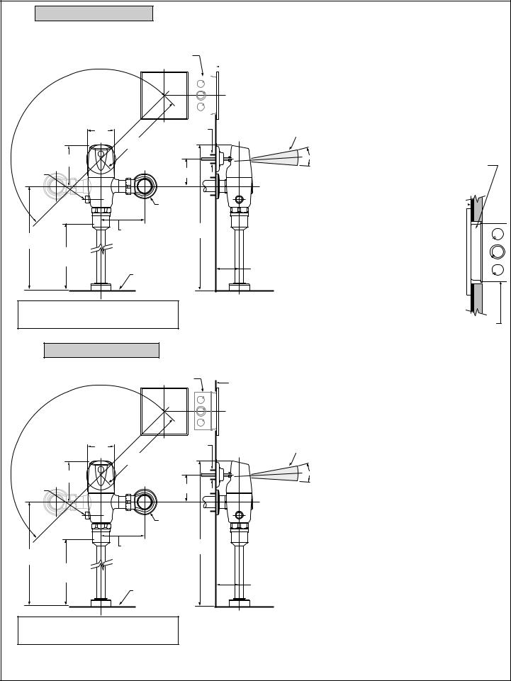
Fig. 1 (Before November 2017)
Roughing-in Dimensions (Front Installation Shown) |
GENERAL DESCRIPTION: |
||||||
Right or Left Hand Installation |
|
|
|
|
|
|
SELECTRONIC® PROXIMITY URINAL FLUSH VALVE |
See (Section 5) for converting Flush |
SEE DETAIL “A” |
Exposed Flushometer for 3/4" Top Spud Fixtures |
|||||
Valve to Left Hand Installation. |
|
|
|
|
|
FINISHED WALL |
|
|
|
|
|
|
|
|
CAUTION: Use only American Standard supplied |
|
|
|
|
|
|
|
transformers and cable sets. Using non-AS supplied |
|
|
|
|
|
|
|
cables, or cutting, splicing or modifying any components |
|
|
|
|
|
|
|
will void the warranty. |
|
|
|
|
|
|
|
|
|
|
|
|
|
|
|
|
|
73 mm |
51 mm (2") HOLE |
|
(2-7/8") |
FOR CONDUIT |
|
305 mm MAX. |
|
|
(12" MAX.) |
|
|
117 mm |
|
MANUAL |
(4-5/8") |
86 mm |
OVERRIDE |
|
|
BUTTON |
|
(3-3/8) |
|
|
(3/4" NPT) |
|
-C-L- |
409 mm |
|
115 - 134 mm |
|
292 mm |
(4-1/2" - 5-1/4") |
(16-1/8") |
|
|
|
(11-1/2") |
|
|
|
*-C-L- |
|
|
152 mm MIN. |
|
|
(6") MIN. |
|
|
TOP OF |
|
|
FIXTURE |
|
DETECTION ZONE: 400 - 800 mm (15-3/4" – 31-1/2") (FACTORY SETTING: 600 mm (23-5/8")
|
|
|
|
|
|
15˚ |
4" (102 mm) SQ. BOX DEVICE COVER (PLASTER RING). |
||||
3/4" (19 mm) HIGH Hubbel-RACO #779 OR EQUAL |
|||||
|
|||||
|
(BY CONTRACTOR). |
||||
|
NOTE: INSTALL PLASTER RING SO THAT SCREW |
||||
|
HOLES ARE ON THE LEFT AND RIGHT SIDE OF BOX. |
||||
|
FINISHED TILE WALL |
|
|
|
|
|
|
||||
|
DETAIL “A” |
||||
76 mm MAX. (3") MAX.
*Note: The Critical Line (-C-L-) on Vacuum
Breaker must typically be 6" (152mm) above fixture. Consult Codes for details.
FINISHED PLASTER WALL
4" (102 mm) SQ. x 3-1/2" (89 mm) DEEP ELECTRICAL BOX Hubbel-RACO #256 OR EQUAL (BY CONTRACTOR).
Fig. 1A (After November 2017)
Roughing-in Dimensions Fig. 1
SEE DETAIL “A” |
FINISHED WALL |
|
|
73 mm |
51 mm (2") HOLE |
DETECTION ZONE: 400 - 800 mm (15-3/4" – 31-1/2") |
|
(2-7/8") |
FOR CONDUIT |
(FACTORY SETTING: 600 mm (23-5/8") |
|
305 mm MAX. |
|
|
|
(12" MAX.) |
|
|
|
114 mm |
|
15˚ |
MANUAL |
(4-1/2") |
86 mm |
|
OVERRIDE |
|
|
|
BUTTON |
|
(3-3/8) |
|
|
|
(3/4" NPT) |
|
|
-C-L- |
406 mm |
|
|
115 - 134 mm |
|
|
292 mm |
(4-1/2" - 5-1/4") |
(16") |
|
|
|
|
|
(11-1/2") |
|
|
|
|
*-C-L- |
|
|
|
152 mm MIN. |
|
|
|
(6") MIN. |
|
|
|
TOP OF |
|
76 mm MAX. |
|
|
(3") MAX. |
|
|
FIXTURE |
|
|
*Note: The Critical Line (-C-L-) on Vacuum
Breaker must typically be 6" (152mm) above fixture. Consult Codes for details.
3 |
M965645 EN REV. 1.7 (5/17) |

RECOMMENDED TOOLS; Fig. 2.
1. Teflon Tape
2.Flat Blade Screwdriver
3.Adjustable Wrench
4.Tape Measure
5.Hacksaw
6.Tubing Cutter
7.File
8.For Sweat Connection; Solder and Torch
9.2.5 mm Hex Wrench
10.1.5 mm Hex Wrench
Fig. 2 |
|
|
|
|
1 |
2 |
|
|
3 |
|
4 |
|
|
|
|
|
10' |
|
|
|
|
|
|
|
|
|
|
|
6 |
|
5 |
|
|
8 |
|
7 |
|
9 |
10 |
PRIOR TO INSTALLATION |
• Flush all water lines prior to operation. Dirt and debris can |
|
Note: Prior to installing the Selectronic™Flush |
cause flush valve to run continuously. |
|
Valve the following items must be installed. |
• With the exception of Stop Valve Inlet, DO NOT |
|
1. Urinal |
||
use pipe sealant or plumbing grease on any |
||
2. Drain line |
||
valve component or coupling! |
||
3. Water supply line |
• Protect the chrome or special finish on the Flushometer. |
|
IMPORTANT: |
||
DO NOT USE toothed tools on finished surfaces to install |
||
• All plumbing and electrical wiring should be |
or service these valves. Also see “Care and Cleaning” |
|
installed in accordance with applicable codes |
section of this manual. |
|
and regulations. |
• This product contains mechanical and/or electrical |
|
• The use of water hammer arrestors is strongly |
||
components that are subject to normal wear. These |
||
recommended for commercial applications. All piping |
||
components should be checked on a regular basis and |
||
behind the walls should be properly secured and |
||
replaced as needed to maintain the valve’s performance. |
||
fastened. |
||
|
||
• Water supply lines must be sized to provide an |
|
|
adequate volume of water for each fixture. |
|
|
|
|
4 |
M965645 EN REV. 1.7 (5/17) |
 Loading...