

Page 1

PRESS BRAKE (ZII)
RG35S–100
OPERATOR'S MANUAL
RG25-125-
E02
-200510
Page 2

PREFACE Read this manual carefully to obtain a thorough knowledge of machine operation and maintenance.
Be sure to follow the instructions to ensure proper procedures and prevent injuries and accidents. Do not operate
the machine by guesswork. Keep the manual at hand
and refer to it whenever you are not sure of how to perform
any of the procedures.
Operator's Manual:
Press Brake (ZII) RG35S-100
© 2005 by AMADA CO., LTD.
No part of this publication may be photocopied or otherwise reproduced without the prior written permission of AMADA CO., LTD.
ii
Printed in Japan
Page 3

CONTENTS
Part I Safety.................................................................................... I-1
1. Safety rules ............................................................................ I-2
2. DANGER and WARNING plates........................................... I-10
Part II Description.......................................................................... II-1
1. Functions ...............................................................................II-2
2. General view ..........................................................................II-3
3. Specifications......................................................................... II-5
4. Dimensions ............................................................................ II-6
5. Standard accessories ............................................................II-9
6. Options..................................................................................II-10
Part III Installation.......................................................................... III-1
1. Summary............................................................................... III-2
1-1. Environmental conditions............................................... III-2
1-2. Input power source......................................................... III-2
1-3. Things to be supplied by customer ................................ III-3
2. Installation procedures.......................................................... III-4
2-1. Location.......................................................................... III-4
2-2. Lifting.............................................................................. III-5
2-3. Foundation ..................................................................... III-6
2-4. Placing ........................................................................... III-6
2-5. Leveling.......................................................................... III-6
2-6. Supplying hydraulic oil ................................................... III-8
2-7. Supplying electric power ................................................ III-8
Part IV Controls..............................................................................IV-1
1. Controls on electrical enclosure............................................ IV-2
2. Controls on upper beam ....................................................... IV-3
3. Hydraulic equipment controls ............................................... IV-4
4. Other controls .......................................................................IV-6
(Continued on next page.)
iii
Page 4

Part V Operation ............................................................................V-1
1. Inspection before start of day’s work .....................................V-3
2. Preparing for operation.......................................................... V-3
3. Turning on power...................................................................V-5
4. Removing tools ......................................................................V-6
4-1. Preparing for removing tools........................................... V-6
4-2. Removing punches .........................................................V-8
4-3. Removing dies ................................................................V-9
5. Installing tools .......................................................................V-11
5-1. Preparing for installing tools ..........................................V-11
5-2. Installing dies .................................................................V-12
5-3. Installing punches ..........................................................V-14
6. Preparing for special bending...............................................V-16
6-1. Installing and removing punch holders .......................... V-16
6-1-1. Removing punch holders ........................................V-16
6-1-2. Installing punch holders ..........................................V-17
6-2. Installing punches rearside front....................................V-18
6-3. Installing wide dies.........................................................V-19
7. Other uses ............................................................................ V-20
7-1. Adjusting punch holders.................................................V-20
7-2. Using one-touch punch holders (option)........................V-23
7-2-1. Installing and removing punches from front ............V-25
7-2-2. Installing and removing punches by sliding them
along groove of rear clamping plates .....................V-28
7-2-3. Installing and removing rear clamping plates..........V-29
8. Aligning tools ........................................................................V-32
8-1. RG35S ...........................................................................V-32
8-2. RG50, RG80, and RG100.............................................. V-34
9. Setting tool origin ..................................................................V-37
10. Bending operation...............................................................V-38
10-1. Setting rising speed change position ...........................V-38
10-2. Setting multiple opening limit .......................................V-39
10-3. Bending worksheet ......................................................V-40
10-3-1. Temporarily setting multiple closing limit...............V-40
10-3-2. Setting worksheet..................................................V-41
10-3-3. Setting bend angle ................................................V-42
11. Turning off power ................................................................V-44
12. Troubleshooting ..................................................................V-46
13. Clearing emergency stop condition .................................... V-48
iv
Page 5

Part VI Maintenance.......................................................................VI-1
1. Inspection before start of day’s work .................................... VI-2
2. Maintaining hydraulic system................................................ VI-4
2-1. Checking hydraulic oil level............................................ VI-4
2-2. Changing hydraulic oil.................................................... VI-5
2-3. Maintaining tools ............................................................ VI-6
3. Lubrication ............................................................................ VI-7
4. Hydraulic circuit diagrams..................................................... VI-8
4-1. RG35S ........................................................................... VI-8
4-2. RG50, RG80, and RG100............................................. VI-10
5. Electric circuit diagrams....................................................... VI-13
v
Page 6

vi
Page 7

Part
I
Safety
1. Safety rules ..................................................................................I-2
2. DANGER and WARNING plates.................................................I-10
I-1
Page 8
1. SAFETY RULES
Observe these safety rules to prevent injuries and accidents:
a) Never modify the machine. If the control circuit or other part of the machine
is modified, the ram may malfunction.
b) Whenever the machine is not in use, remove the key from the POWER
ON/OFF keyswitch, and hand it to the chief operator for custody.
c) Assign trained operators to the operation and maintenance of the machine.
d) Inspect the machine before the start of the day's work.
e) Install the machine with a rear clearance of at least 1000 mm {40 in.} where
it is not exposed to direct sunlight. If the electrical equipment of the
machine is overheated as a result, the machine may malfunction.
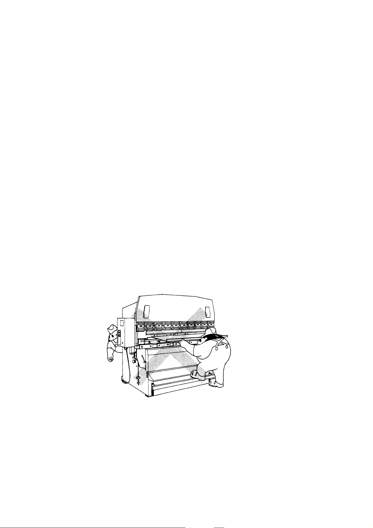
f) Before starting the operation of the machine, check that there are no
persons and obstacles around the machine. Pay particular attention to the
rear of the machine. Never place hand tools and parts on the installed dies
and the lower beam.
g) Never put your hand or hands between the punches and dies.
I-2
Page 9
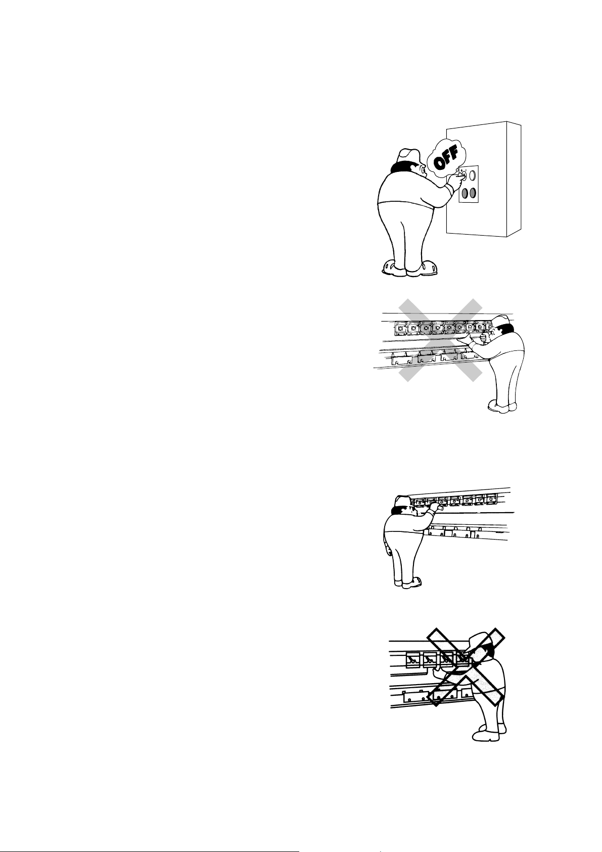
h) When changing the tools, strictly observe the following rules:
• Before installing and removing the
dies, turn the POWER ON/OFF
keyswitch to OFF, remove the key from
the keyswitch, and keep it by yourself.
(Install and remove the dies as
described in “4. Removing tools” and
“5. Installing tools” in Part V.)
• Before installing and removing the
punches, turn the multiple closing limit
setting handwheel to close the ram to
the desired position, turn the POWER
ON/OFF keyswitch to OFF, remove the
key from the keyswitch, and keep it by
yourself. Never put your hand or
hands between the punch and die to
support the punch. (Install and
remove the punches as described in
“4. Removing tools” and “5. Installing
tools” in Part V.)
• Securely fix the punches, dies, and die
holders before applying pressure to
them.
• When you install and remove the tools
with an assistant operator or
operators, be sure to coordinate your
work with them.
• Never put your hands between the
punches and dies to support a punch,
for example.
• When you install a tool by sliding it
sideways, take care not to get your
hand pinched between it and another
tool already installed.
I-3
Page 10
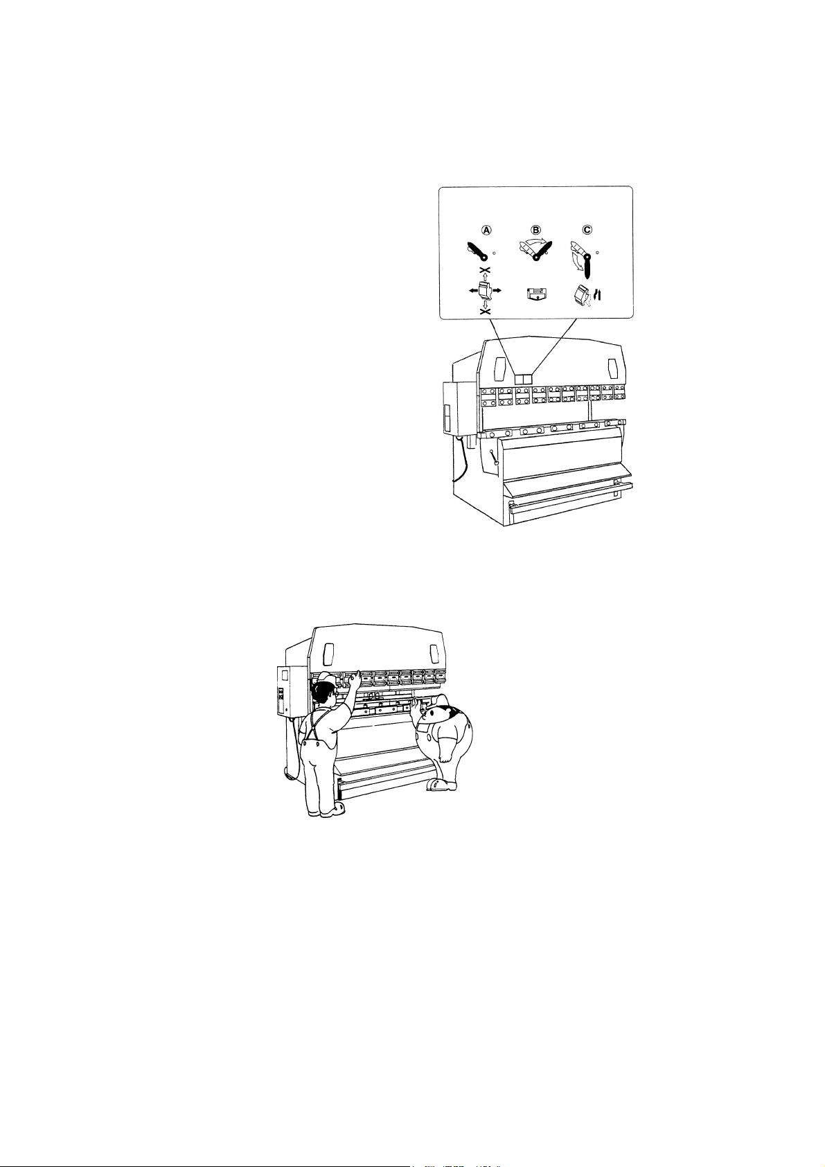
If your machine is equipped with optional one-touch punch holders, keep the
following rules:
• When applying pressure to the
punches or bending the worksheet,
ONE-TOUCH PUNCH HOLDER
LEVER POSITIONS
POSITION POSITION POSITION
turn the punch holder levers to the
position ◯B.
POSITIONS FOR OPERATING
LEVER AND INSTALLING AND
REMOVING PUNCHES
• Install or remove the punch holder
levers only in the position ◯B.
• Affix the punch holder lever position
sticker in an easy-to-see place to
prevent procedural mistakes.
i) When you bend worksheets with an assistant operator or operators, you
must press the bar pedal after fully ensuring the safety of all of them.
I-4
Page 11
j) Before adjusting the stoppers, turn the POWER ON/OFF keyswitch to OFF,
remove the key from the keyswitch, and keep it by yourself. Be sure to
adjust the stoppers from the rear of the machine.
k) Correctly set the position where the bending speed of the ram is to be
changed. If this position is not correctly set, the worksheet may start to
bend unexpectedly.
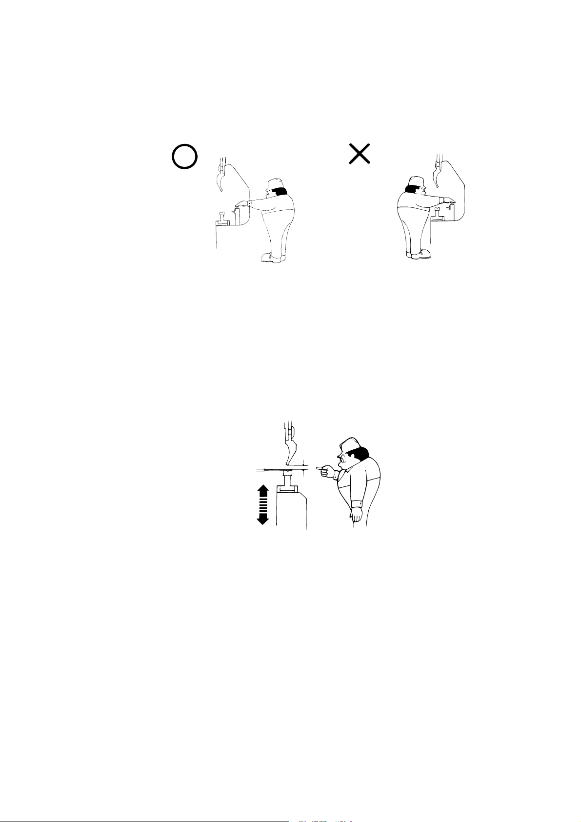
l) When bending a small worksheet, set the stroke length of the ram to 6 mm
{0.24 in.} or less, and hold the worksheet as shown on the next page. Take
care not to get your fingers pinched between the punches and dies or
between the punches and worksheet.
6 mm
{0.24 in.}
or less
I-5
Page 12
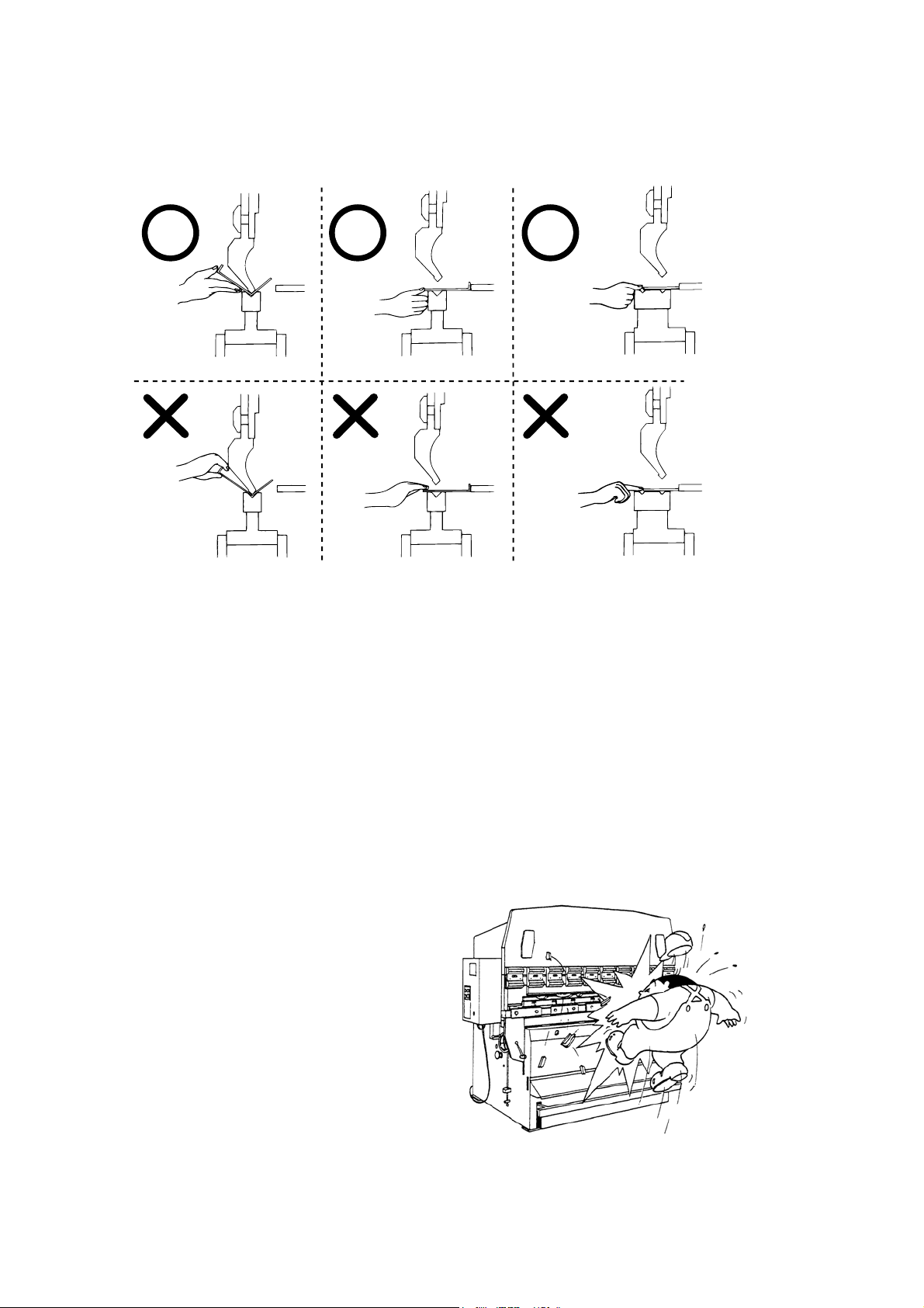
Hold the worksheet as shown below.
m) If your machine is equipped with an optional backgauge, push the
worksheet against the stoppers of the backgauge after the backgauge is
properly positioned. Otherwise the worksheet may be pushed forward
when the backgauge moves forward.
n) Use Amada genuine punches and dies on the machine. The machine
performs various controls by reference to the Amada genuine punches and
dies. Non-genuine punches and dies are different in brittleness and
allowable tonnage from the genuine punches and dies. Use of such nongenuine tools may cause various troubles and detract from safety of the
machine.
o) Apply to the installed tools a pressure
that is not higher than the allowable
tonnage marked on them. Unless a
proper pressure is applied to them, the
tools may break and scatter in a
dangerous manner.
When 2V-dies are used, use the Vgroove toward the rear of the machine
for additional safety from breakage.
I-6
Page 13
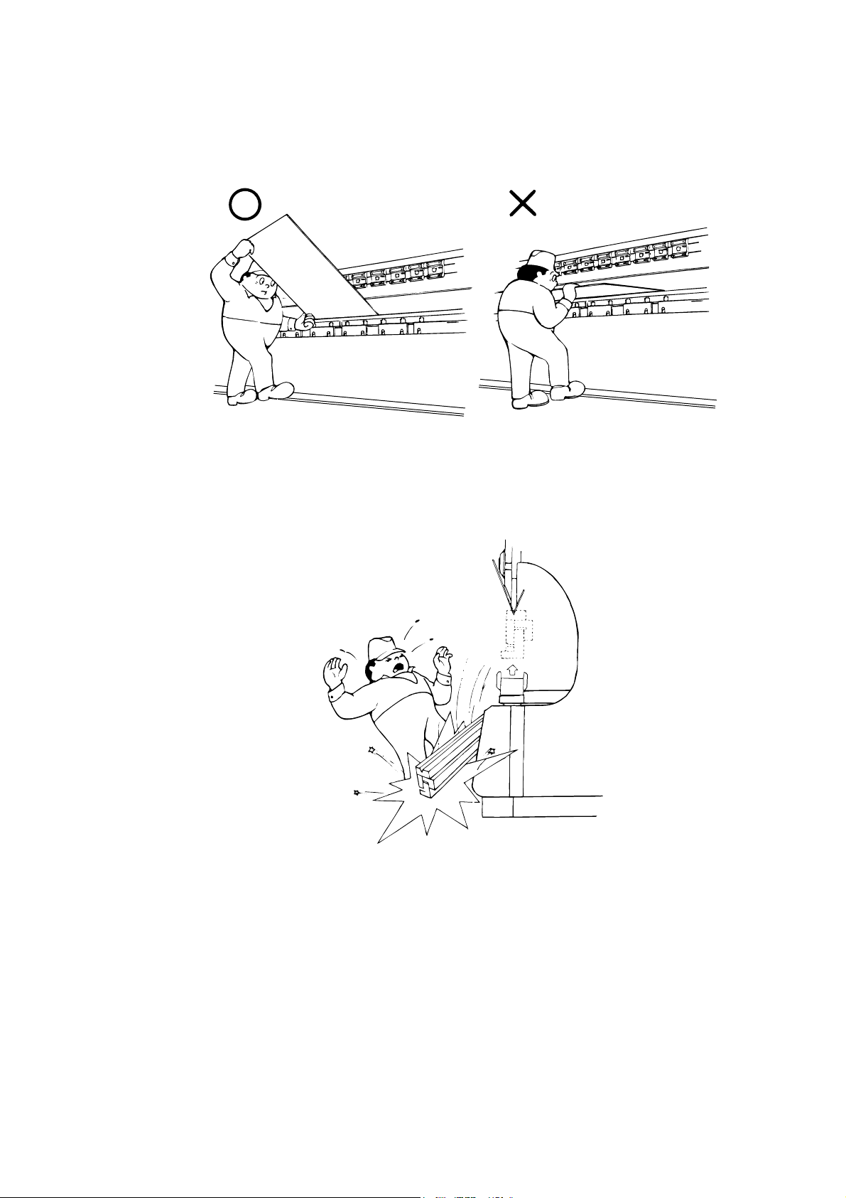
p) When bending a large worksheet, be careful of its springing upward. Hold
one side of the worksheet or otherwise be ready for its springing upward.
q) Before bending each worksheet, check that the tools are securely installed
and tightened. With a sharp bend or U-bend, the punches and dies may
eat into the worksheet and fall together with the worksheet.
I-7
Page 14
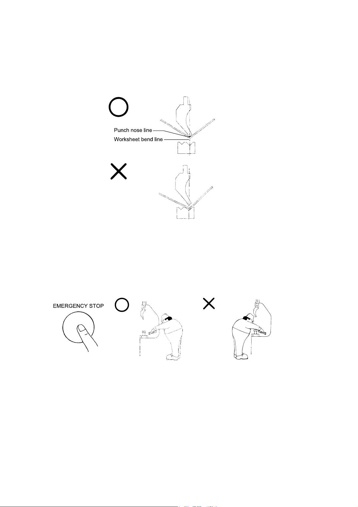
r) When rebending the same worksheet, align the nose line of the punches
with the bend line of the worksheet. If the worksheet is rebent without
aligning the lines, abnormal noise may be produced, and the tools may
break and scatter in a dangerous manner.
s) Whenever trouble occurs during the operation of the machine, press one of
the EMERGENCY STOP buttons, turn the POWER ON/OFF keyswitch to
OFF, remove the key from the keyswitch, keep it by yourself, and fix the
problem. When picking a worksheet that has fallen into the machine, be
sure to do so from the rear of the machine. As soon as the machine
develops trouble, report it to the chief operator.
I-8
Page 15
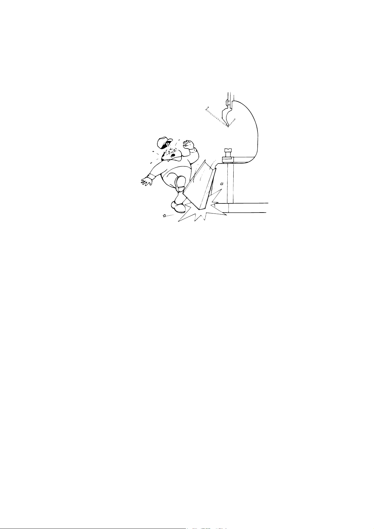
t) If the machine suddenly loses its power due to a power failure, the ram may
open to the maximum opening limit. In such a case, hold the worksheet
over the ram so that it does not fall.
u) Before walking away from the machine, turn the POWER ON/OFF
keyswitch to OFF, remove the key from the keyswitch, and keep it by
yourself.
v) Before opening the electrical enclosure, be sure to turn off the machine
circuit breaker. You may receive an electric shock if you touch any parts in
the electrical enclosure.
w) Be sure to perform periodic maintenance on the machine. For the items of
maintenance to be performed, refer to Part VI, Maintenance.
x) Before maintaining or cleaning the machine, turn off the shop circuit breaker,
relieve the residual hydraulic pressure in the machine, and post a sign to
inform other workers that the machine is under maintenance.
y) When relocating the machine, ask AMADA about how to move the machine.
If moved incorrectly, the machine may turn over.
I-9
Page 16
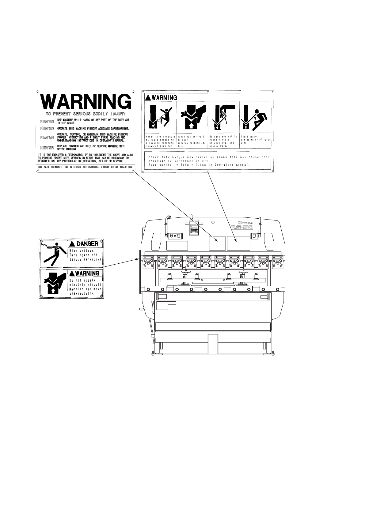
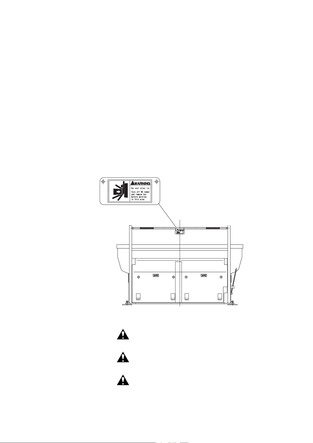
2. DANGER AND WARNING PLATES
Keep the DANGER and WARNING plates well noticeable and never remove
them.
I-10
Page 17
Hazard seriousness level
DANGER
WARNING
CAUTION
Indicates an imminently hazardous situation
which, if not avoided, will result in death or
serious injury.
Indicates a potentially hazardous situation
which, if not avoided, could result in death or
serious injury.
Indicates a potentially hazardous situation
which, if not avoided, may result in minor or
moderate injury.
I-11
Page 18

I-12
Page 19

Part
II
Description
1. Functions .................................................................................... II-2
2. General view ............................................................................... II-3
3. Specifications.............................................................................. II-5
4. Dimensions ................................................................................. II-6
5. Standard accessories .................................................................II-9
6. Options....................................................................................... II-10
II-1
Page 20

1. FUNCTIONS
This machine is a hydraulic press brake of the central pressure
application and parallel rising type. It has the following features:
• The hydraulic circuit is simplified to minimize oil leakage and facilitate
maintenance.
• A main cylinder is installed at the center of the ram to minimize the
distortion produced in the upper and lower beams during pressure
application.
• Installed at the center of the ram, a bearing guide unit slides up and
down along the main cylinder surface that doubles as sliding surface,
in order to keep the upper and lower beams accurately parallel.
• A punch-to-die clearance setting unit allows the ram stroke length to
be set to a required minimum and the working efficiency to be
enhanced as a result.
• The bar pedal can be pressed as required to adjust the ram approach
speed or stop the ram mid-stroke. This is ideal for bending
worksheets on which scribed lines must be aligned with the punch
nose line.
• Punch holders and die holders are installed in the upper and lower
beams and provide for easy installation of punches and dies,
respectively.
• Standard tools are light in mass, easy to carry, available in many
types, and adaptable to a variety of bending operations. (For the
tools, refer to their catalogs.)
II-2
Page 21
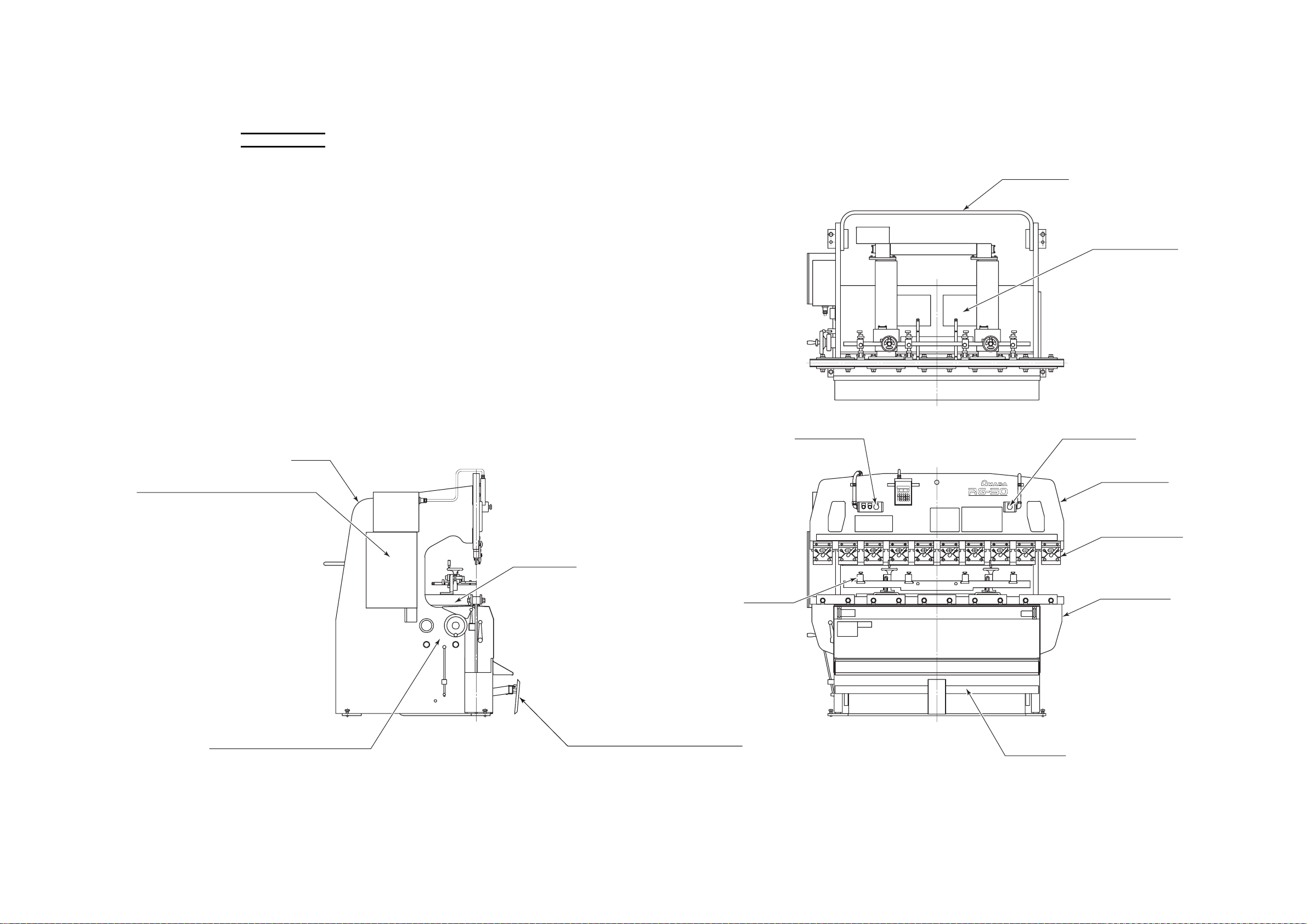
2. GENERAL VIEW
NOTE
O This drawing shows the general view of the RG50 machine.
REAR GUARD
HYDRAULIC UNIT
Hydraulic oil tank and hydraulic
drive unit are located at rear
of lower beam.
FRAME
ELECTRICAL ENCLOSURE
Power distribution and control circuits
are built in. Power and hydraulic pump
motor switches are located.
Shop's main power source is connected
to terminals in this enclosure.
HYDRAULIC
EQUIPMENT CONTROLS
Knobs and levers required for
operation of ram are located.
SUPPORTER
PEDAL STOPPER
Pressed to allow ram to be operated
only by single operator. Bar pedal can
be pressed only when foot is placed on
pedal stopper to disable pedal stopper.
STOPPER
EMERGENCY
STOP BUTTON
EMERGENCY
STOP BUTTON
UPPER BEAM
PUNCH HOLDER
LOWER BEAM
BAR PEDAL
Pressed as required to adjust ram approach
speed or stop ram mid-stroke.
II-3
Page 22

II-4
Page 23

3. SPECIFICATIONS
Metric unit system (International system of units)
Item
Maximum bend length (mm) 1250 2085 2505 3100
Press capacity (kN) 343 490 784 980
Stroke length (mm) 100 100 100 100
Open height without punch holders (mm) 370 370 370 370
Approach speed at 50/60 Hz (mm/sec) 46/55 38/45 38/45 49/59
Bending speed at 50/60 Hz (mm/sec) 8/9.5 7/8.5 7/8.5 8.3/10.1
Moving-down speed (mm/sec) 40 35 52 52
Number of main cylinders
(number of auxiliary cylinders)
Hydraulic pump motor output (kW) 2.2 3.7 5.5 7.5
Hydraulic oil tank capacity (L) 26 51 51 65
Machine mass (kg) 1600 2900 5100 6400
RG35S RG50 RG80 RG100
1 1 (2) 1 (2) 1 (2)
Model
Power supply of 380/400/460 V
Item
RG35S RG50 RG80 RG100
Primary power cable (mm2)223.58
Load current (A) 9.1 13.2 23.0 30.0
Model
Power supply of 200/230 V
Item
Primary power cable (mm2) 3.5 3.5 8 14
Load current (A) 17.0 22.3 38.0 49.1
RG35S RG50 RG80 RG100
Model
II-5
Page 24

English unit system
Item
Maximum bend length (in.) 49.2 82.1 98.6 122.0
Press capacity (US tonf) 38.6 55.1 88.2 110.2
Stroke length (in.) 3.9 3.9 3.9 3.9
Open height without punch holders (in.) 14.6 14.6 14.6 14.6
Approach speed at 50/60 Hz (ips) 1.8/2.2 1.5/1.8 1.5/1.8 1.9/2.3
Bending speed at 50/60 Hz (ips) 0.31/0.37 0.28/0.33 0.28/0.33 0.33/0.40
Moving-down speed (ips) 1.6 1.4 2.0 2.0
Number of main cylinders
(number of auxiliary cylinders)
Hydraulic pump motor output (HP) 3.0 5.0 7.4 10.1
Hydraulic oil tank capacity (US gal) 6.9 13.5 13.5 17.2
Machine mass (lb) 3530 6390 11250 14110
RG35S RG50 RG80 RG100
1 1 (2) 1 (2) 1 (2)
Model
Power supply of 380/400/460 V
Item
RG35S RG50 RG80 RG100
Primary power cable (mm2)223.58
Load current (A) 9.1 13.2 23.0 30.0
Model
Power supply of 200/230 V
Item
Primary power cable (mm2) 3.5 3.5 8 14
Load current (A) 17.0 22.3 38.0 49.1
RG35S RG50 RG80 RG100
Model
II-6
Page 25
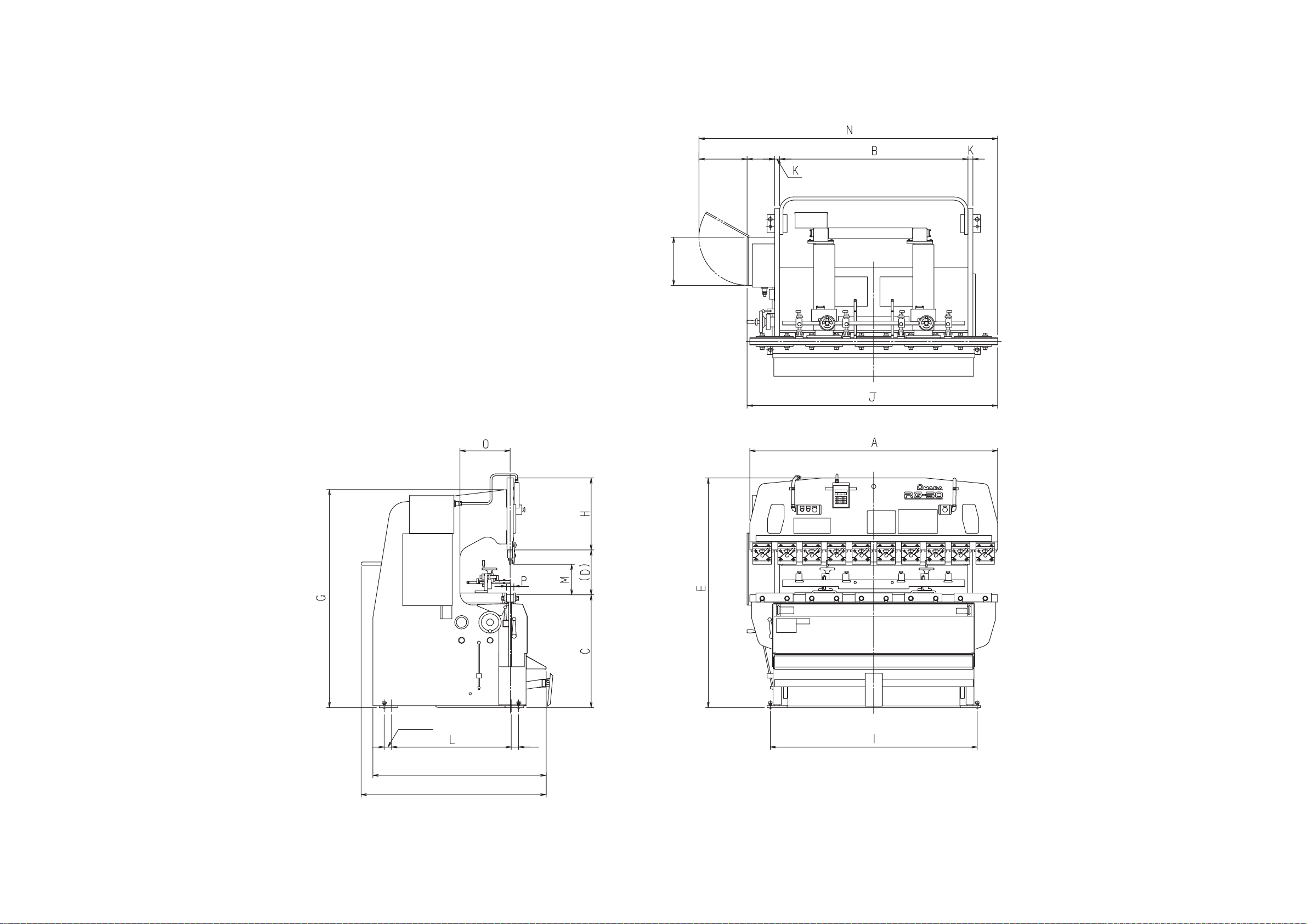
4. DIMENSIONS
400 mm
{15.7 in.}
390 mm
{15.4 in.}
225 mm
{8.9 in.}
F*
F**
60 mm
{2.4 in.}
60 mm
{2.4 in.}
*Depth of RG35S, RG50, RG80
**Depth of RG100
II-7
Page 26

Unit: mm
Model A B C (D) E F G H I J K L M N O P
RG35S 1200 1020 935 370 1955 1495 1800 650 920 1355 25 445 250 1745 200 60
RG50 2000 1520 940 370 1910 1495 1820 600 1670 2025 40 970 250 2410 400 60
RG80 2400 2050 945 370 2065 1495 1920 750 2240 2515 60 970 250 2895 400 60
RG100 3000 2550 1035 370 2305 1555 2110 900 2750 3065 60 1090 250 3445 400 90
Unit: in.
Model A B C (D) E F G H I J K L M N O P
RG35S 47.2 40.2 36.8 14.6 77 58.9 70.9 25.6 36.2 53.3 0.98 17.5 9.8 68.7 7.9 2.4
RG50 78.7 59.8 37.0 14.6 75.2 58.9 71.7 23.6 65.7 79.7 1.57 38.2 9.8 94.9 15.7 2.4
RG80 94.5 80.7 37.2 14.6 81.3 58.9 75.6 29.5 88.2 99.0 2.36 38.2 9.8 114.0 15.7 2.4
RG100 118.1 100.4 40.7 14.6 90.7 61.2 83.1 35.4 108.3 120.7 2.36 42.9 9.8 135.6 15.7 3.5
II-8
Page 27

5. STANDARD ACCESSORIES
No. Item Description Qty Applicable model
Tool box
Single-ended
wrench
45° offset box
1 Tool set
2 Hydraulic oil Super Hydraulic oil 56 (Nippon oil)
3 Stopper 2 (0) ALL
4 Supporter 4 (2) ALL
5 2V-die holder
6 Punch holder
7 Bulb LS-6 2 ALL
Note: Quantity values enclosed in parentheses apply when machine is equipped with optional
backgauge.
wrench
Allen wrench
Brass bar
Hammer 1/2 pound
Size L: 830 mm {32.7 in.} long,
75 mm {3.0 in.} high
Size S: 412 mm {16.2 in.} long,
75 mm {3.0 in.} high
30 mm
13 mm
14 × 17 mm
8 mm, long type
5 mm
φ20 × 200 mm
1ALL
26 L
{6.9 US gal}
51 L
{13.5 US gal}
65 L
{17.2 US gal}
1RG35S
2RG50
3RG80
4RG100
1 RG35S, 50
6RG35S
10 RG50
12 RG80
15 RG100
RG35S
RG50, 80
RG100
II-9
Page 28

6. OPTIONS
Name Function
Auto-backgauge system
Remote foot pedals
RR-type front gauge
Worksheet follower
One-touch punch holders*
Dial-type punch holders*
Double-side punch
holders*
Optical safety device
• Can set worksheet contact positions (bending positions) for up
to 99 processes.
• Allows continuous bending by programmed operation.
• Displays set values and current position of backgauge by LEDs.
• Has such functions as elongation compensation, backlash
compensation, and timing.
• Like bar pedal, open and close ram.
• Installed at front of machine to support worksheet with stoppers
and used for positioning worksheet at front of machine.
• Supports large worksheet during bending while following bend
angle.
• Allow punches to be installed and removed by levers without
use of any other tool.
• Allow height of punches to be adjusted with dials.
• Allow punches to be installed on both of front and rear sides.
• Emits light beams at front of installed punches and dies and
automatically stops machine as soon as two or more light
beams are interrupted by operator’s body parts or other objects.
Side guards
Two-hand control buttons
Two-person foot pedals
*Standard option
• Close up gaps in left and right frames and prevent operator’s
body parts from entering machine.
• Simultaneously pressed to open and close ram in place of bar
pedal.
• Simultaneously pressed by two persons to open and close ram
in place of bar pedal.
II-10
Page 29

Part
III
Installation
1. Summary.....................................................................................III-2
1-1. Environmental conditions.....................................................III-2
1-2. Input power source...............................................................III-2
1-3. Things to be supplied by customer ......................................III-3
2. Installation procedures................................................................III-4
2-1. Location................................................................................III-4
2-2. Lifting....................................................................................III-5
2-3. Foundation ...........................................................................III-6
2-4. Placing .................................................................................III-6
2-5. Leveling................................................................................III-6
2-6. Supplying hydraulic oil .........................................................III-8
2-7. Supplying electric power ......................................................III-8
When the machine is delivered to you directly from AMADA, it is usually
transported by the specialized carrier. Instruct them where to install the
machine.
Select such a machine installation place where the space required for
worksheet loading, part unloading and machine maintenance can be
secured and where the machine can be installed on a flat surface
without ground subsidence. For details, refer to “2. Installation
procedures”.
WARNING
O Moving or carrying the machine may not only
damage the machine, but also is dangerous. Ask
a qualified contractor to perform this work.
III-1
Page 30

1. SUMMARY
1-1. Environmental conditions
• Keep the machine at least 10 m {33 ft} away from a welder or any
other equipment that may produce electrical noise and magnetic
fields.
• Where the ambient temperature is not higher than 5 °C {41 °F}, keep
the machine and hydraulic pump motor energized during the day's
work.
• The higher the humidity in the place where the machine is installed,
the lower the insulation performance of its electric parts becomes.
This results in the premature degradation of the electric parts. Do
not install the machine in such a humid place.
• Install the machine in a place where it is not subjected to dust, dirt,
and organic or corrosive gases.
1-2. Input power source
Power requirement: 200/230/380/400/460 VAC±10% (transformer tap
and motor wiring is required), 3 phases, 50/60 Hz±1 Hz
NOTICE
O Supply the machine from a power source independent of a welder or any
other equipment that may produce line voltage variations. Otherwise the
machine may misoperate.
III-2
Page 31

1-3. Things to be supplied by customer
Primary power cable
Four-conductor VCT cable (600V polyvinyl chloride insulated cabtyre
cable)
380/400/460 V specification
Model Each conductor size
RG35S 9.1 A
RG50
RG80 3.5 mm
RG100 8 mm
200/230 V specification
Model Each conductor size
RG35S 17.0 A
RG50
RG80 8 mm
RG100 14 mm
2 mm
3.5 mm
Current carrying
capacity
2
13.2 A
2
2
23.0 A
30.0 A
Current carrying
capacity
2
22.3 A
2
2
38.0 A
49.1 A
III-3
Page 32

2. INSTALLATION PROCEDURES
2-1. Location
Select a place where an ample space can be secured for the machine
by paying full attention to the required floor area and the following items:
• There must be no pillars and other obstacles where the tools are
installed and removed. (At least 835 mm {33 in.} long tools must be
able to be horizontally installed and removed through the left and right
frame gaps of the machine.)
• The ceiling must be at least 1000 mm {40 in.} from the top of the
machine. (Take the height of the base plates into account.)
• There must be an additional space to locate a tool storage case and
any other necessary items.
• Space must be available for worksheet loading, part unloading,
machine maintenance, and other tasks.
A space of 1000 mm {40 in.} or more must be available at the rear of
the machine.
An enough space must be available for the cover of the electrical
enclosure to be opened.
A space of 1000 mm {40 in.} or more must be available from the cover
edge at the right side of the ram.
NOTICE
O Do not install the machine in a place where it is exposed to dust from such
operations as sandblasting and to direct sunlight, rain and wind.
O It is ideal to install the machine on a concrete floor to prevent deflection due to
ground subsidence.
1000 mm
{40 in.}
700 mm
{28 in.}
300 mm
{12 in.}
1000 mm
{40 in.}
III-4
FRONT
Page 33
2-2. Lifting
WARNING
For the mass of the machine, refer to “Machine mass” in the
specifications on pages II-5 and II-6. This mass is that of a standard
specification machine and increases when the machine is fitted with
optional units.
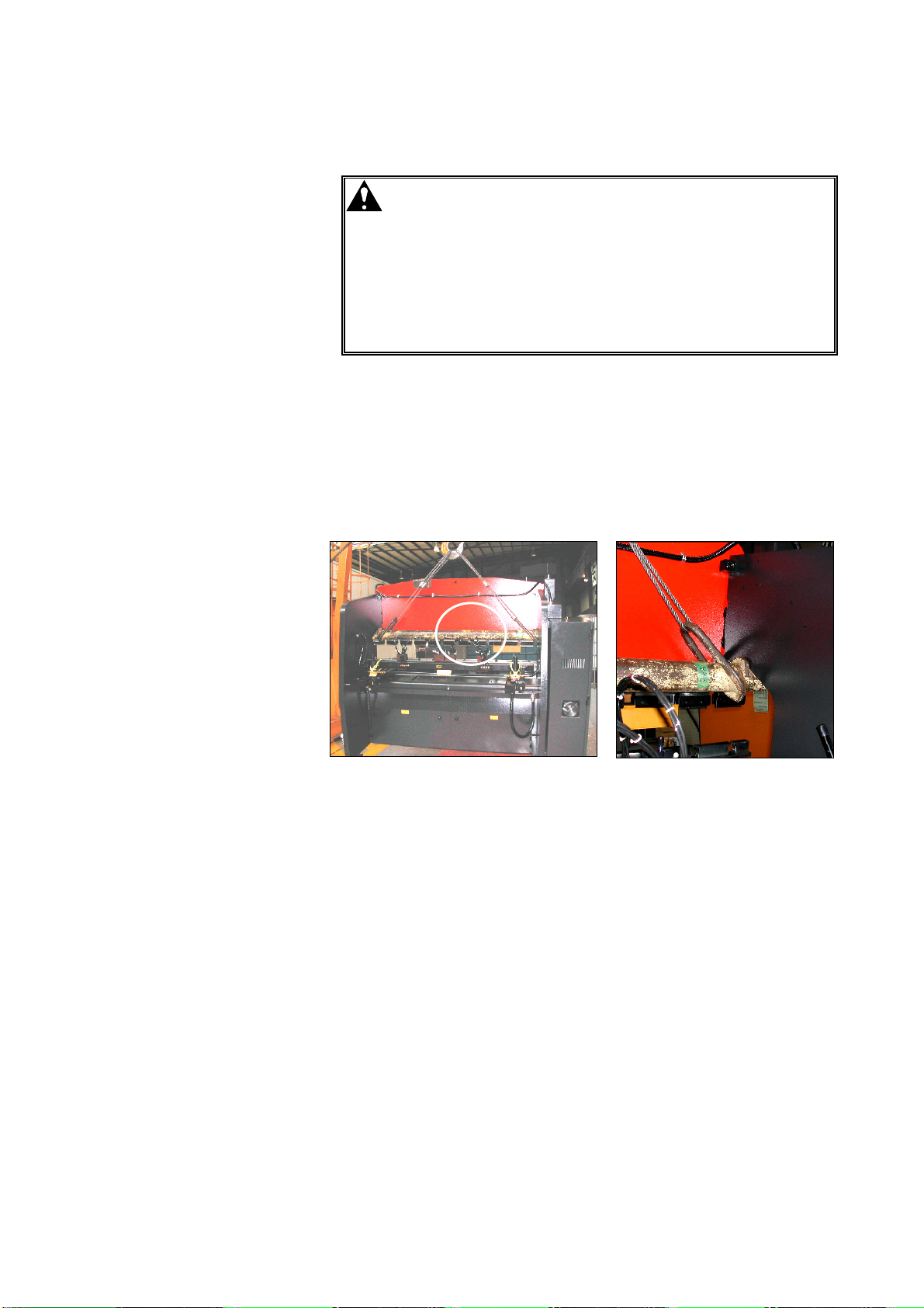
When lifting the machine, pass special lifting devices through the frame
gaps as shown below, apply wire rope slings to the lifting devices, and
lift the machine with a crane.
O The machine requires special lifting
devices. Never use steel pipes or apply
wire rope slings directly to the frame of the
machine. Doing so is not only
dangerous, but also damages the
machine.
O If it is necessary to lift the machine for
layout change, for example, ask a qualified
contractor to perform the work.
III-5
Page 34

2-3. Foundation
To maintain its bending accuracy, install the machine on a flat concrete
floor constructed strong enough to carry its mass. Before carrying the
machine to the location, execute the foundation work by referring to the
foundation drawing supplied by AMADA. If the ground is soft with a
bearing capacity of 49 kN/m
foundation with steel bars or the like.
2-4. Placing
Usually, fixing the machine with anchor bolts is not necessary.
Place base plates (150 mm {6 in.} square and 9 to 16 mm {0.4 to 0.6 in.}
thick steel plates) on the foundation, and install the machine on the base
plates.
2-5. Leveling
2
{0.51 US tonf/ft
2
}
or less, reinforce the
After installing the machine, be sure to level it. Unless it is properly
leveled, it will not perform and last as originally designed. Leveling the
machine calls for the use of spirit levels accurate to 0.05 mm/m {0.0006
in./ft} or less, a thickness gauge, and stretch bars (or die holders).
Levelness in left-right direction
Place a spirit level at the center of the ram.
III-6
Page 35

Levelness in front-back direction
Place a stretch bar (or die holder) on the two leveling pins inside each of
the left and right frames of the machine.
Insert a thickness gauge between the front or rear leveling pin and the
stretch bar.
The thickness of the thickness gauge to be inserted is marked at the
front left or right of the ram.
The position where to insert the thickness gauge depends on the
position of the mark on the lower beam as shown below.
When the mark is placed at the upper front of the ram, insert the
thickness gauge between the front leveling pin and the stretch bar.
When the mark is placed at the lower front of the ram, insert the
thickness gauge between the rear leveling pin and the stretch bar.
Leveling machine
Place a spirit level on each stretch bar (or die holder).
Adjust the level of the machine to within 0.05 mm/m {0.0006 in./ft} in the
front-back and left-right directions by turning the leveling bolts at the four
corners of the machine.
III-7
Page 36
2-6. Supplying hydraulic oil
The hydraulic unit is located at the rear of the machine. Remove the
top cover or covers of the hydraulic oil tank, and pour the recommended
hydraulic oil into the hydraulic oil tank to the specified level of the oil
gauge. The specified level is near the middle mark of the oil gauge
when the ram is at the maximum opening limit. (Refer to “2.
Maintaining hydraulic system” in Part VI.)
Model Tank capacity
RG35S 26 L {6.9 US gal}
RG50, RG80 51 L {13.5 US gal}
RG100 65 L {17.2 US gal}
Recommended hydraulic oil: Amada Oil A-110
Esso Nuto H46
Mobil DTE 25
Shell Tellus Oil 46
(ISO VG46 equivalent)
The hydraulic oil Super Hyrando 56 of Nippon Oil Co., Ltd. is delivered
with the machine.
2-7. Supplying electric power
WARNING
Connecting power source
Connect the power source to the machine as described below.
1 Turn off the machine circuit breaker and the shop circuit breaker.
2 Pull the three-phase power cable through the power inlet at the
bottom of the electrical enclosure, and connect it to the L1, L2 and
L3 primary terminals of the terminal block.
3 Securely connect the grounding conductor to the ground terminal.
After wiring the power cable, check the voltage with a tester.
Primary power cable Four-conductor cable
Input power source 200/230/380/400/460 VAC±10%, 3 phases,
O Have a qualified electrician perform all
electric work to prevent accidents and
damage.
O Before making the electrical connections,
be sure to turn off the shop circuit breaker.
O Be sure to connect the grounding
conductor for safety.
50/60 Hz±1 Hz
III-8
Page 37

Checking rotation direction of hydraulic pump motor
WARNING
Check the rotation direction of the hydraulic pump motor as described
below.
1 Remove the cover of the rotating shaft of the hydraulic pump
motor.
2 Turn on the shop circuit breaker and the machine circuit breaker.
3 Turn the POWER ON/OFF keyswitch to ON.
4 Push back the bar pedal lock lever, if provided.
5 Press the HYD. ON button. The button illuminates, and the
hydraulic pump motor starts.
6 Check the rotation direction of the hydraulic pump motor, and
immediately press the HYD. OFF button. The hydraulic pump
motor stops, and the HYD. ON button extinguishes.
O To check the rotation direction of the
hydraulic pump motor, do not get any part
of your body or clothing too close to any
rotating parts (like the coupling of the
motor to the pump).
If you have any part of your body or
clothing caught in a rotating part, you may
get hurt.
CORRECT
DIRECTION
[RG50, RG80, RG100] [RG35S]
When the hydraulic pump motor runs in the correct direction, its
wiring is properly connected. Replace the cover of the rotating
shaft, and complete the connecting procedure.
When the hydraulic pump motor runs in the reverse direction, turn
the POWER ON/OFF keyswitch to OFF, turn off the machine circuit
breaker and the shop circuit breaker, and interchange two of the
three power conductors L1, L2 and L3 connected to the primary
terminals in the electrical enclosure. This makes correct wiring
connections. Replace the cover of the rotating shaft, and
complete the connecting procedure.
III-9
Page 38

NOTICE
O Supply electric power to the machine from a source different from that of a
welder or any other equipment that produces electrical noise. Use a welder,
electric drill, sander, or grinder at least 10 m {33 ft} away from the machine.
O The type of primary power cable varies with machine model. Maintain the
supply voltage variations to within ±10%.
O Use a grounding conductor of size not smaller than that of the L1, L2, and L3
power conductors.
III-10
Page 39

Part
IV
Controls
1. Controls on electrical enclosure.................................................... IV-2
2. Controls on upper beam ................................................................... IV-3
3. Hydraulic equipment controls .................................................... IV-4
4. Other controls ............................................................................ IV-6
IV-1
Page 40

1. CONTROLS ON ELECTRICAL ENCLOSURE
[6] MACHINE
CIRCUIT
BREAKER
[2] POWER LAMP
[1] POWER ON/OFF
KEYSWITCH
[5] EMERGENCY
[4] HYD. OFF BUTTON
[3] HYD. ON BUTTON
STOP BUTTON
[1] POWER ON/OFF keyswitch
Used to turn on and off the power of the machine.
[2] POWER lamp
Illuminates to indicate that the machine circuit breaker is turned to ON to
supply electric power to the machine.
[3] HYD. ON button
Pressed to illuminate itself and start the hydraulic pump motor.
[4] HYD. OFF button
Pressed to extinguish the HYD. ON button and stop the hydraulic pump
motor.
[5] EMERGENCY STOP button
Pressed in an emergency to stop all motions of the machine. When
pressed and locked, the EMERGENCY lamp on the upper beam is
illuminated.
[6] Machine circuit breaker
Used to turn on and off the power to the electrical enclosure.
IV-2
Page 41

2. CONTROLS ON UPPER BEAM
[1][1] [2]
[2][2]
[3][3] [3]
(Not installed on RG35S)
[3][3]
[1] EMERGENCY lamp
Illuminates to indicate that the machine is under the emergency stop
condition.
[2] DOWN button
Pressed to force down the ram.
[3] EMERGENCY STOP button or buttons
Pressed in an emergency to stop all motions of the machine. When
pressed and locked, the EMERGENCY lamp is illuminated.
NOTE
O The RG35S have the one EMERGENCY STOP button on the upper beam.
The RG50, RG80, and RG100 have the two EMERGENCY STOP buttons.
IV-3
Page 42
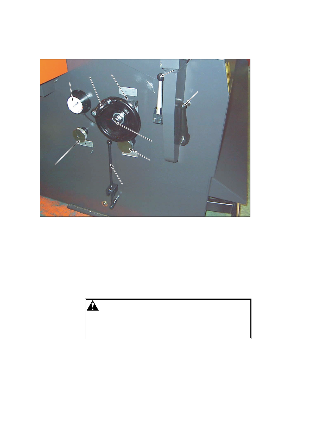
3. HYDRAULIC EQUIPMENT CONTROLS
[1][1]
[4][4]
[6] [6]
[9] [9]
[8] [8]
[3] [3]
[7] [7]
[5] [5]
[2] [2]
[1] Pressure adjusting knob (Regulator)
Used to adjust the pressure applied between the punches and dies.
Turned counterclockwise (–) to decrease the pressure and clockwise (+)
to increase the pressure. To obtain the maximum press capacity,
usually keep the knob turned fully clockwise (+).
[2] Bar pedal lock lever (Not installed on RG35S)
Used to lock the bar pedal in the fully pressed state when the ram is
closed to the multiple closing limit. Lock and unlock the bar pedal while
it is pressed.
DANGER
O When the bar pedal lock lever is used, the
bar pedal is fixed in the fully pressed state,
and the applied pressure is maintained.
The ram may follow the multiple closing
limit setting made with its handwheel and
may produce an excessive pressure.
IV-4
Page 43

[3] Multiple opening limit setting lever
Used to set the multiple opening limit (stop position) of the ram. Open
the ram to the position where you want to stop the ram, and turn down
the lever to set the stop position. Turn up the lever to clear the stop
position and open the ram to the maximum opening limit.
[4] Pressure gauge
Indicates the pressure applied between the punches and dies when the
cut-off valve knob is turned fully counterclockwise.
[5] Cut-off valve knob
Used to stop the flow of hydraulic oil to the pressure gauge so that the
pressure gauge does not indicate the pressure. Turned fully clockwise
when there is no need to check the pressure.
[6] Multiple closing limit setting handwheel
Used to set the multiple closing limit of the ram. Turned clockwise to
raise the multiple closing limit and counterclockwise to lower the multiple
closing limit when the handwheel lock knob is turned fully
counterclockwise.
NOTICE
O Do not turn the multiple closing limit setting handwheel counterclockwise with
the bar pedal pressed and held. Doing so may break the multiple closing
limit setting mechanism and render the machine unusable.
[7] Handwheel lock knob
Used to lock the multiple closing limit setting handwheel after setting the
multiple closing limit of the ram with the handwheel. Turned fully
clockwise to lock the handwheel.
NOTICE
O When the handwheel lock knob is overloosened to unlock the multiple closing
limit setting handwheel, the handwheel may not be locked again. To loosen
the knob, turn it once to twice.
[8] Rising speed change position setting lever
Used to change the rising speed of the ram from the approach speed to
the bending speed (low speed).
[9] Digital multiple closing limit display (Digicollar)
Located behind the multiple closing limit setting handwheel and
indicates the current position of the ram set with the handwheel. Press
the reset button alongside the display to reset the display to “0”.
IV-5
Page 44

4. OTHER CONTROLS
[1] Bar pedal
Pressed to adjust the ram approach speed or stop the ram mid-stroke.
The ram closes to the multiple closing limit when the bar pedal is fully
pressed and opens to the multiple opening limit or maximum opening
limit when the bar pedal is released.
[2] Pedal stopper
Pressed to allow the ram to be operated only by a single operator. The
bar pedal can be pressed only when a foot is placed on the pedal
stopper to disable the pedal stopper. When the foot is released from
the pedal stopper, the pedal stopper opens under its own mass and
does not allow the bar pedal to be pressed. The pedal stopper can be
moved to any desired working position.
[2] PEDAL
[2] PEDAL
STOPPER
STOPPER
[1] BAR PEDAL[1] BAR PEDAL
IV-6
Page 45

Part
V
Operation
1. Inspection before start of day’s work .......................................... V-3
2. Preparing for operation ............................................................... V-3
3. Turning on power ........................................................................V-5
4. Removing tools ........................................................................... V-6
4-1. Preparing for removing tools................................................ V-6
4-2. Removing punches ..............................................................V-8
4-3. Removing dies .....................................................................V-9
5. Installing tools ............................................................................ V-11
5-1. Preparing for installing tools................................................ V-11
5-2. Installing dies ......................................................................V-12
5-3. Installing punches ...............................................................V-14
6. Preparing for special bending ....................................................V-16
6-1. Installing and removing punch holders ...............................V-16
6-1-1. Removing punch holders..............................................V-16
6-1-2. Installing punch holders................................................ V-17
6-2. Installing punches rearside front .........................................V-18
6-3. Installing wide dies ..............................................................V-19
7. Other uses .................................................................................V-20
7-1. Adjusting punch holders......................................................V-20
7-2. Using one-touch punch holders (option) .............................V-23
7-2-1. Installing and removing punches from front ................. V-25
7-2-2. Installing and removing punches by sliding them
along groove of rear clamping plates........................... V-28
(Continued on next page.)
V-1
Page 46

7-2-3. Installing and removing rear clamping plates............... V-29
8. Aligning tools .............................................................................V-32
8-1. RG35S ................................................................................V-32
8-2. RG50, RG80, and RG100................................................... V-34
9. Setting tool origin ....................................................................... V-37
10. Bending operation.................................................................... V-38
10-1. Setting rising speed change position ................................ V-38
10-2. Setting multiple opening limit ............................................ V-39
10-3. Bending worksheet ...........................................................V-40
10-3-1. Temporarily setting multiple closing limit.................... V-40
10-3-2. Setting worksheet....................................................... V-41
10-3-3. Setting bend angle ..................................................... V-42
11. Turning off power ..................................................................... V-44
12. Troubleshooting ....................................................................... V-46
13. Clearing emergency stop condition ......................................... V-48
V-2
Page 47

1. INSPECTION BEFORE START OF DAY’S WORK
Inspection before the start of the day's work is very important for the
safe and trouble-free operation of the machine. Before starting its
operation, inspect the machine as described in “1. Inspection before
start of day’s work” in Part VI.
2. PREPARING FOR OPERATION
Prepare the machine for operation as described below.
1 Turn up the multiple
opening limit setting
lever to open the ram
to the maximum
opening limit.
2 Pull forward the rising
speed change
position setting lever
to prevent the ram
from unexpectedly
closing.
3 Loosen the
handwheel lock knob,
and turn the multiple
closing limit setting
handwheel fully
counterclockwise.
V-3
Page 48

4 Turn the cut-off valve
knob fully
counterclockwise to
enable the pressure
gauge.
5 Turn the pressure
adjusting knob fully
clockwise (+).
V-4
Page 49

3. TURNING ON POWER
Start the machine as described below.
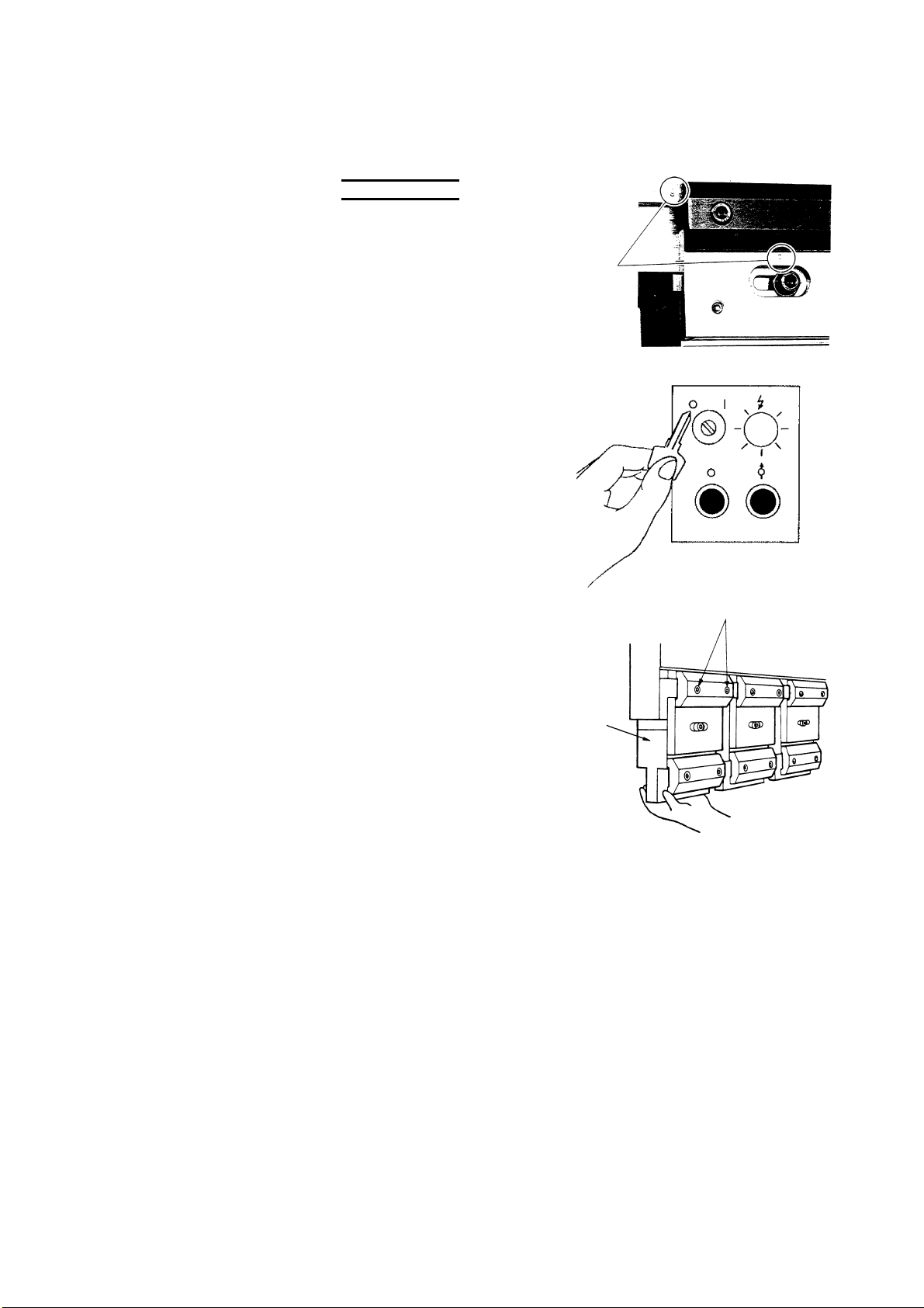
1 Turn on the shop circuit breaker.
2 Turn the machine circuit
breaker to ON.
The POWER lamp illuminates.
3 Insert the key in the POWER
ON/OFF keyswitch, and turn
the keyswitch to ON.
4 Push back the bar pedal lock
lever, except RG35S.
5 Press the HYD. ON button.
The button illuminates, and the
hydraulic pump motor starts.
V-5
Page 50

4. REMOVING TOOLS
DANGER
O Never put your hand or hands between the
punches and dies.
O When changing the tools, strictly observe
the following cautions:
{ Before removing the dies, turn the
POWER ON/OFF keyswitch to OFF,
remove the key from the keyswitch, and
keep it by yourself.
| Before removing the punches, turn the
multiple closing limit setting handwheel
to close the ram to the desired position,
turn the POWER ON/OFF keyswitch to
OFF, remove the key from the
keyswitch, and keep it by yourself.
Never put your hand or hands between
the punch and die to support the
punch.
} When you remove the tools with an
assistant operator or operators, be sure
to coordinate your work with them.
O Be sure to remove the punches first and
then the dies.
4-1. Preparing for removing tools
Before removing the tools, set the multiple opening limit of the ram as
described below.
NOTE
O The maximum opening limit refers to the bottom dead center of the ram, and
the multiple opening limit refers to the stop position of the ram set with the
multiple opening limit setting lever.
1 Check the punch-die
combination dimension H
shown right.
2 Loosen the handwheel lock knob to unlock the multiple closing limit
setting handwheel.
3 Turn the multiple closing limit setting handwheel fully
counterclockwise.
4 Clear the pedal stopper, and fully press the bar pedal.
The ram closes to the multiple closing limit and stops.
V-6
Page 51

5 With the bar pedal
fully pressed, turn the
multiple closing limit
setting handwheel
clockwise to set the
height between the
punch holders and die
holders to the
dimension H plus 2 to
H + 2 to 3 mm
{0.08 to 0.12 in.}
2 to 3mm
2 to 3 mm
2 to 3 mm
(0.08 to 0.12 in.)
{0.08 to 0.12 in.}
{0.08 to 0.12 in.}
3 mm {0.08 to 0.12
in.}.
NOTICE
O Do not turn the multiple closing limit setting handwheel
counterclockwise with the bar pedal pressed and held. Doing so may
break the multiple closing limit setting mechanism. Even when the
handwheel is turned counterclockwise, the ram does not open.
O To adjust the multiple closing limit of the ram to a lower position, release
the bar pedal to open the ram, turn the multiple closing limit setting
handwheel counterclockwise, and press the bar pedal again.
6 Release the bar
pedal, and turn up the
multiple closing limit
setting lever to clear
the multiple opening
limit of the ram.
The ram opens to the
maximum opening
limit.
7 Clear the pedal stopper, press the bar pedal again to close the ram
to the position you want to set as the multiple opening limit, and
hold the bar pedal in that state.
The ram stops in that position.
8 Turn down the
multiple opening limit
setting lever to set the
multiple opening limit
of the ram.
NOTE
O Positively turn down the multiple opening limit setting lever so that the
ram does not open.
9 Release the bar pedal.
The ram remains at the multiple opening limit.
V-7
Page 52

10 To perform the subsequent
tasks safely, press the HYD.
OFF button, turn the POWER
ON/OFF keyswitch to OFF, and
remove the key from the
keyswitch.
4-2. Removing punches
WARNING
Remove the punches from the punch holders as described below.
1 Loosen the fixing
bolts of the punch
clamping plate or
plates.
The punch drops onto
the V-groove of the
die.
O When removing the punch in step 1, do
not support it from below with your hand
as shown below. Otherwise you may get
your hand or fingers pinched.
FIXING
BOLT
V-8
2 Slide the punch
sideways to remove it.
LOOSEN
FIXING BOLTS
PUNCH DROPS ONTO
V-GROOVE OF DIE
Page 53

When optional one-touch punch holders (refer to page V-23)
are available:
1 Turn the punch holder lever or
levers counterclockwise as
shown right.
2 Slide the punch sideways to
remove it.
4-3. Removing dies
After removing the punches, remove the dies from the ram as described
below.
Removing 2V-dies
Loosen the die fixing bolts, and remove the die.
DIE
WASHER
BOLT
Removing 1V-dies for forming sashes
Remove the 1V-dies for forming sashes as described for the 2V-dies on
the above.
1V-DIE
(FOR FORMING SASHES)
DIE HOLDER
2V-DIE
DIE FIXING BOLT
DIE HOLDER
DIE FIXING BOLT
DIE HOLDER FIXING BOLT
V-9
Page 54

Removing 1V-dies
Loosen the front die-block fixing bolts, and remove the die together with
the die block.
NOTICE
O The rear clamping plates of the ram and die blocks establish the reference
surface for aligning the punches and dies. Never loosen them.
CLAMPING
PLATES
REAR FRONT
DIE BLOCK
DIE BLOCK
1V-DIE
REAR
RAM
FRONT
CLAMPING
PLATES
V-10
Page 55

5. INSTALLING TOOLS
WARNING
O Never put your hand or hands between the
punches and dies.
O When changing the tools, strictly observe
the following cautions:
{ Before installing the dies, turn the
POWER ON/OFF keyswitch to OFF,
remove the key from the keyswitch, and
keep it by yourself.
| Before installing the punches, turn the
multiple closing limit setting handwheel
to close the ram to the desired position,
turn the POWER ON/OFF keyswitch to
OFF, remove the key from the
keyswitch, and keep it by yourself.
Never put your hand or hands between
the punch and die to support the
punch.
} When you install the tools with an
assistant operator or operators, be sure
to coordinate your work with them.
O Be sure to install the dies first and then the
punches.
5-1. Preparing for installing tools
Before installing the tools, wipe off the upper beam and ram tool
installation surfaces and tools, refer to “4-1. Preparing for removing
tools” in this Part, and set the multiple opening limit of the ram.
V-11
Page 56

5-2. Installing dies
Install the dies on the ram as described below.
Installing 2V-dies
NOTICE
O Install 2V-dies so that the
V-groove to be used faces
the rear of the machine by
considering safety in the
event of die breakage.
When the die holders are
installed with the step facing
the rear as shown right, the
V-groove to be used comes
to the rear.
O When using two or more die
holders, install them with a
clearance of about 5 mm
{0.2 in.} between them.
NOTE
O When using two or more dies, install them so as to create no gap between
them.
STEP
REAR
REAR
FRONT
(OPERATOR SIDE)
ABOUT 5 mm
ABOUT 5 mm {0.2 in.}
FRONT
(OPERATOR SIDE)
{0.2 in.}
1 Place the die holder for the 2V-
die on the top of the ram.
2 Set the die fixing bolts
as shown right.
SPRING
WASHER
BOLT
3 Slide the 2V-die from
the front of the
machine onto the die
holder with the Vgroove to be used
facing the rear.
4 Fasten the die holder
with the die holder
fixing bolts.
DIE HOLDER
a + 2 mm {0.08 in.}
2V-DIE
DIE FIXING BOLT
DIE HOLDER FIXING BOLT
DIE HOLDER
V-12
Page 57

Installing 1V-dies for forming sashes
Install the 1V-dies for forming sashes as described for the 2V-dies on
the previous page.
1V-DIE
(FOR FORMING SASHES)
DIE HOLDER
Installing 1V-dies
NOTICE
O The rear clamping plates of the ram and die blocks establish the reference
surface for aligning the punches and dies. Never loosen them.
CLAMPING
PLATES
DIE FIXING BOLT
DIE HOLDER FIXING BOLT
1V-DIE
REAR
REAR FRONT
DIE BLOCK
DIE BLOCK
NOTE
O Depending on the type of 1V-die, the tool height and ram stroke length may
not be large enough for the punch and die to properly engage. In such a
case, use the optional die block on the ram. Install the die block by paying
attention to its orientation as shown below.
RAM
FRONT
CLAMPING
PLATES
1 Place the 1V-die together with the die block on the top of the ram.
2 Tighten the front die-block fixing bolts.
V-13
Page 58

5-3. Installing punches
WARNING
O When installing a punch, do not support it
from below with your hand as shown
below. Otherwise you may get your hand
or fingers pinched.
After installing the dies, install the punches to the punch holders as
described below.
NOTE
O When installing sectionalized punches
and dies, stagger them by about 5 mm
{0.2 in.} as shown right to prevent the
worksheet from being scratched.
PUNCH
1 Slide the punch into
the V-groove of the
die as shown right.
2 Determine the
installation position of
the punch by sliding it
left and right, and
lightly tighten the
fixing bolts of the
punch clamping plate
or plates.
UPPER
BEAM
PUNCH
HOLDER
CLAMPING
PLATE
2 to 3 mm {0.08 to 0.12 in.}
PUNCH
DIE
ABOUT 5 mm {0.2 in.}
V-14
Page 59

When optional one-touch punch holders (refer to page V-23)
are available:
1 Insert the fall prevention tongue of the punch into the fall
prevention groove of the clamping plate or plates as shown lower
left, and slide the punch into position.
2 Tighten the punch holder lever or levers clockwise to prevent the
punch from as shown lower right.
V-15
Page 60

6. PREPARING FOR SPECIAL BENDING
6-1. Installing and removing punch holders
When special-shaped punches are used or when a worksheet comes
into contact with punch holders during bending, the punch holders may
be removed from the upper beam for bending the worksheet. Install
and remove the punch holders as described below.
6-1-1. REMOVING PUNCH HOLDERS
1 Remove the punches from the punch holders. (Refer to “4.
Removing tools” in this Part.)
2 Turn the POWER
ON/OFF keyswitch to
OFF, and remove the
key from the
keyswitch.
3 Turn up the multiple
opening limit setting
lever to clear the
multiple opening limit
of the ram.
The ram opens to the
maximum opening
limit.
4 Loosen the clamping
bolts of each punch
holder while
supporting the punch
holder with the other
hand, and remove the
punch holder.
CLAMPING BOLTS
PUNCH
HOLDER
V-16
Page 61
6-1-2. INSTALLING PUNCH HOLDERS
NOTE
O The numbers that specify
their installation position of
the punch holders are
marked on the punch
holders and upper beam.
Install each punch holder in
the position that matches its
marked number.
1 Turn the POWER
ON/OFF keyswitch to
OFF, and remove the
key from the
keyswitch.
NUMBERS
2 While pushing each
punch holder against
CLAMPING BOLTS
the upper beam with
one hand, fingertighten its clamping
bolts with the other
hand.
PUNCH
HOLDER
3 Install the punches and dies along the entire length of the upper
beam and ram, respectively. (Refer to “5. Installing tools” in this
Part.)
4 Align the punches and dies. (Refer to “8. Aligning tools” in this
Part.)
V-17
Page 62

5 Place a worksheet
along the entire length
of the dies, clear the
pedal stopper, and
press the bar pedal to
apply a pressure
lower than the
allowable tonnage of
the tools and bring the
punch holders into
tight contact with the
upper beam.
6 With the upper beam and punch holders in tight contact, retighten
the clamping bolts of the punch holders.
PRESSURE GAUGE
6-2. Installing punches rearside front
WARNING
Depending on the bend shape of
parts, the punches may have to be
installed rearside front as shown
right. In such a case, install the
punches as described below.
1 Turn the POWER ON/OFF
keyswitch to OFF, and remove
the key from the keyswitch.
O If you reach between the upper beam and
ram to install the clamping plates at the
rear of the punch holders, you may get
your hands pinched. Never do so.
O When you install the clamping plates at
the rear of the punch holders, turn off the
power of the machine and optional
backgauge, and go to the rear of the
machine.
FRONT
V-18
Page 63

2 Remove the fixing
bolts of the clamping
plate of each punch
holder, and remove
the clamping plate.
3 Install the clamping
plates at the rear of
the punch holders,
and fasten them with
the fixing bolts.
4 Install the punches. (Refer to “5. Installing tools” in this Part.)
6-3. Installing wide dies
With the machine model RG100 having bar attached to the clamping
plate at the top of the ram, removing the bar allows 90 mm {3.5 in.} wide
dies to be installed.
FRONT
V-19
Page 64
7. OTHER USES
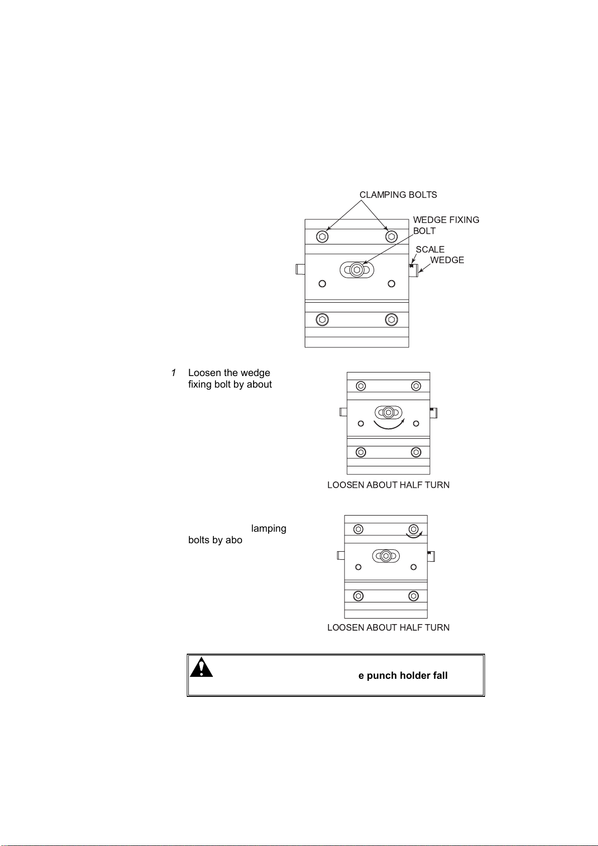
7-1. Adjusting punch holders
If the worksheet is not bent to a uniform angle along the entire bend
length, adjust the punch holders as described below.
Before adjusting the punch
holder, record the current
value of the scale marked
on the wedge. This value
serves as a guide when
returning the punch holder
to the original state.
1 Loosen the wedge
fixing bolt by about a
half turn with an Allen
wrench.
2 Loosen either of the
left and right clamping
bolts by about a half
turn with an Allen
wrench, and lightly
tighten it again.
CAUTION
O If both of the two clamping bolts are
loosened, the punch holder falls. Be
sure to loosen only either of them.
V-20
Page 65

3 Apply the accessory
brass bar to either of
the left and right sides
of the wedge, and
strike it with a
hammer.
NOTE
O To bend the
worksheet to an acute
angle, strike the brass
bar from right to left
facing the front of the
machine.
O To bend the
worksheet to an
obtuse angle, strike
the brass bar from left
to right facing the front
of the machine.
Guide for adjusting punch holders:
Consider bending a 1.6 mm {0.06 in.} thick worksheet of mild steel
to an angle of about 90° with a die V-groove opening width of 10
mm {0.4 in.}. In this example, moving the wedge by one
graduation of the scale changes the bend angle by 20 to 30’.
NOTICE
O When striking the wedge with a hammer, be sure to use the accessory
brass bar. Never strike the wedge directly with the hammer.
4 After completing the
adjustment, securely
tighten the wedge
fixing bolt.
5 While pressing and
holding the bar pedal
to apply pressure to
the punch and die,
securely tighten the
clamping bolts.
CAUTION
O The pressure to apply here should be
about one-third of the allowable
tonnage of the tools.
V-21
Page 66

6 Actually bend the worksheet to check that the bend angle is
uniform.
7 If the bend angle is not uniform, repeat the procedure from the
beginning.
V-22
Page 67
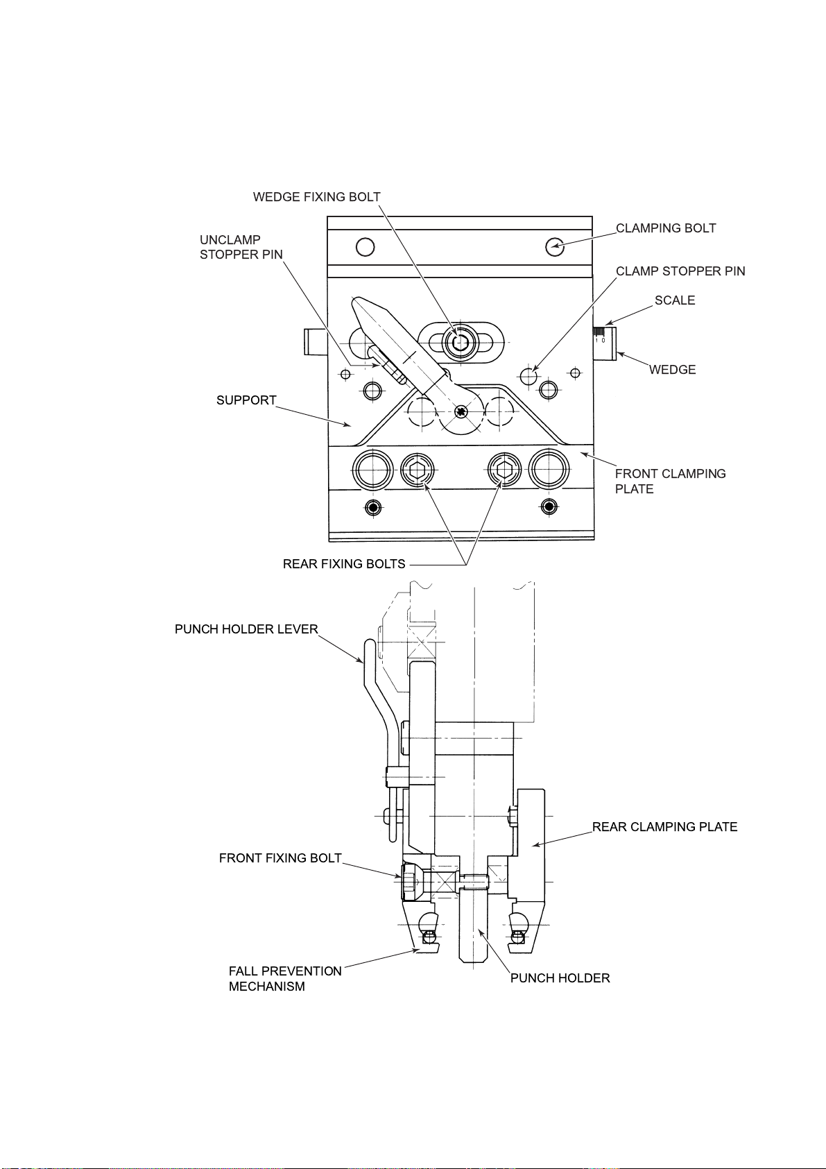
7-2. Using one-touch punch holders (option)
Names of parts
WEDGE FIXING BOLT
UNCLAMP
STOPPER PIN
SUPPORT
REAR FIXING BOLTS
PUNCH HOLDER LEVER
CLAMPING BOLT
CLAMP STOPPER PIN
SCALE
WEDGE
FRONT CLAMPING
PLATE
FRONT FIXING BOLT
FALL PREVENTION
MECHANISM
REAR CLAMPING PLATE
PUNCH HOLDER
V-23
Page 68

Punch holder lever positions
Position ◯
A
Turn the lever to this position to install and remove the punches by
sliding them sideways.
NOTE
O When the lever is turned to the position ◯A the punches cannot be installed
and removed from the front of the machine.
Position ◯B (Basic lever position)
Turn the lever to this position to clamp the punches and to install and
remove the lever itself.
Position ◯
Turn the lever to this position to install and remove 100 mm {4 in.} or
shorter sectionalized punches from the front of the machine.
C
V-24
Page 69

7-2-1. INSTALLING AND REMOVING PUNCHES FROM FRONT
WARNING
Installing punches from front
WARNING
CAUTION
O Before installing and removing the
punches, turn the POWER ON/OFF
keyswitch to OFF, remove the key from the
keyswitch, and keep it by yourself.
O If the punch is 100 mm {4 in.} or more in
length, do not install it from the front of the
machine. You cannot safely support it
with your hand or hands.
O When installing
a punch from the
front of the
machine, push it
straight up.
If the punch is
pushed up
inclined, the
clamping plate remains open and allows
the punch to fall.
Check that the punch does not fall when
pulled down, and then release it.
1 Turn down the
unclamp stopper pin,
and turn the punch
holder lever
counterclockwise to
the position ◯
2 Hold the sides of the
punch as shown right,
and push the punch
upward so that it
becomes parallel with
the punch holder.
C
.
V-25
Page 70

3 Turn the punch holder
lever clockwise to the
position ◯
A
, and turn
up the unclamp
stopper pin.
4 After positioning the punch, turn the punch holder lever clockwise
to the position ◯
B
to clamp the punch.
5 Install the punch as described in “5-3. Installing punches” in this
Part.
V-26
Page 71

Removing punches from front
WARNING
O If the punch is 100 mm {4 in.} or more in
1 Turn down the
unclamp stopper pin,
and turn the punch
holder lever to the
position ◯
C
.
2 Hold the sides of the
punch as shown right,
and remove the
punch from the front
of the machine.
length, do not remove it from the front of
the machine. You cannot safely support
it with your hand or hands.
3 Turn the punch holder
lever clockwise to the
position ◯
A
, and turn
up the unclamp
stopper pin.
V-27
Page 72

7-2-2. INSTALLING AND REMOVING PUNCHES BY SLIDING THEM
ALONG GROOVE OF REAR CLAMPING PLATES
WARNING
O Before installing and removing the
punches, turn the POWER ON/OFF
keyswitch to OFF, remove the key from the
keyswitch, and keep it by yourself.
Installing punches in rear clamping plates
1 Insert the fall
prevention tongue of
the punch into the fall
prevention groove of
the rear clamping
plate as shown right.
2 After positioning the
punch, turn the rear
fixing bolts clockwise
with an Allen wrench
to clamp the punch.
FALL PREVENTION
MECHANISM
3 Install the punch as
described in “5-3.
Installing punches” in
this Part.
NOTICE
O When turning the rear
fixing bolts with the
Allen wrench to clamp
the punch, be sure to
tighten the left and
right of the rear
clamping plate parallel
and with equal force.
If you overtighten the
clamping plate with
the leverage of a long
wrench or pipe, the
durability of the
belleville springs may
suffer.
REAR FIXING
BOLTS
V-28
Page 73

Removing punches from rear clamping plates
WARNING
1 Turn the rear fixing
bolts
counterclockwise by
one turn with an Allen
wrench as shown
right.
2 Remove the punch by
sliding it sideways.
O When loosening the rear fixing bolts, do
not turn them counterclockwise by more
than one and a half turns. If the bolts are
turned by more than one and a half turns,
the rear fall prevention mechanism does
not operate, allowing the punch to fall in a
dangerous manner.
TURN REAR FIXING BOLTS
COUNTERCLOCKWISE
REAR FIXING
BOLTS
7-2-3. INSTALLING AND REMOVING REAR CLAMPING PLATES
WARNING
Before installing and removing the rear clamping plates, be sure to
remove the punch holder units from the upper beam.
O Before installing and removing the rear
clamping plates, turn the POWER ON/OFF
keyswitch to OFF, remove the key from the
keyswitch, and keep it by yourself.
Removing rear clamping plates
1 Place the punch
holder unit so that the
rear clamping plate
faces down as shown
right.
REAR CLAMPING
PLATE
V-29
Page 74

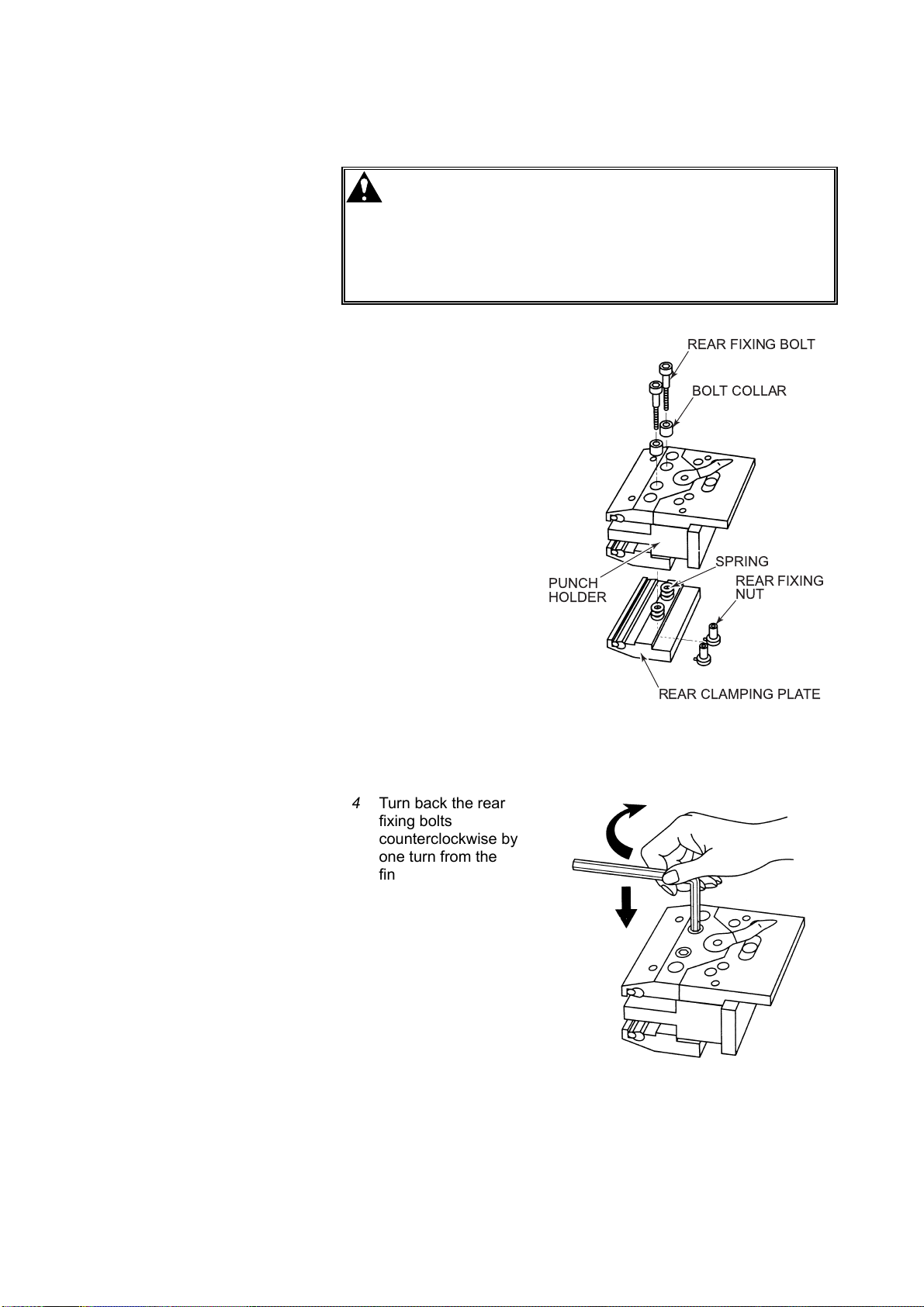
2 Turn the rear fixing
bolts
counterclockwise with
an Allen wrench, and
remove them from the
rear fixing nuts.
REAR FIXING BOLT
BOLT COLLAR
3 Remove the bolt
collars from the front
clamping plate, lift the
punch holder, and
remove the rear
clamping plate.
Assemble the rear
clamping plate as
shown right, and store
it.
REAR FIXING BOLT
BOLT COLLAR
SPRING
REAR CLAMPING
PLATE
V-30
Page 75
Installing rear clamping plates
WARNING
O Do not turn the rear fixing bolts
1 Place the punch
holder unit as shown
right with the keys of
the rear fixing nuts
aligned with the nut
anti-rotation keyways
of the rear clamping
plate.
2 Insert the springs in
the spring seats of the
rear clamping plate,
and position the
punch holder as
shown right.
3 Insert the bolt collars
into the rear fixing-bolt
installation holes of
the front clamping
plate, and fingertighten the rear fixing
bolts clockwise with
an Allen wrench while
pushing down the
front clamping plate.
counterclockwise by more than one turn
from the finger-tightened position. If the
bolts are turned by more than one turn, the
rear fall prevention mechanism may not
operate, allowing the punch to fall in a
dangerous manner.
REAR FIXING BOLT
BOLT COLLAR
SPRING
PUNCH
HOLDER
REAR CLAMPING PLATE
REAR FIXING
NUT
4 Turn back the rear
fixing bolts
counterclockwise by
one turn from the
finger-tightened
position, so that the
punch can be slid
sideways.
V-31
Page 76

8. ALIGNING TOOLS
8-1. RG35S
WARNING
After installing the tools, align them as described below.
When you reinstall the dies after removing them together with the die
holders, align them again.
1 Turn the POWER ON/OFF
keyswitch to ON.
O Never put your hand or hands between the
punches and dies.
O Apply to the installed tools a pressure that
is not higher than the allowable tonnage
marked on them. Unless a proper
pressure is applied to them, the tools may
break and scatter in a dangerous manner.
2 Press the HYD. ON button.
The button illuminates, and the
hydraulic pump motor starts.
3 Clear the pedal stopper, and
fully press the bar pedal.
The ram closes to the multiple
closing limit and stops.
CLEARANCE
V-32
Page 77

4 With the bar pedal fully pressed, slowly turn the multiple opening
limit setting handwheel clockwise.
The ram slowly closes. (Its multiple closing limit rises.)
5 When the clearance between
the punches and punch holders
is about to disappear, turn the
multiple closing limit setting
PRESSURE
GAUGE
handwheel further clockwise,
while checking the pressure
gauge, in order to apply the
pressure until the pointer of the
pressure gauge indicates the
NC9 value.
WARNING
O If the allowable tonnage of the installed
tools is smaller than the NC9 value, set
their origin with a pressure smaller than
the allowable tonnage.
6 Tighten the handwheel lock knob to lock the multiple closing limit
setting handwheel.
7 Press the bar pedal two to three times until the dies completely
engage with the punches.
8 With the bar pedal fully
pressed, retighten the fixing
bolts of the punch clamping
plates. (If the optional onetouch punch holders are used,
retightening their levers is not
necessary.)
9 When the dies are 2V-dies or
sash forming 1V-dies, with the
bar pedal fully pressed, tighten
the fixing bolts of the dies.
10 Release the bar pedal to complete the tool aligning procedure.
The ram opens to the multiple opening limit and stops.
V-33
Page 78

8-2. RG50, RG80, and RG100
CAUTION
1 Turn the POWER ON/OFF
keyswitch to ON.
2 Check that the bar pedal lock
lever is not pulled forward. If
pulled forward, push it back.
3 Press the HYD. ON button.
The button illuminates, and the
hydraulic pump motor starts.
O When you are aligning the tools with the
bar pedal locked, do not stop the hydraulic
pump motor by pressing the HYD. OFF
button or turning the POWER ON/OFF
keyswitch to OFF. Doing so will open the
ram.
UNLOCK BAR PEDAL
PUSH BACK
BAR PEDAL LOCK LEVER
V-34
4 Clear the pedal stopper, and
fully press the bar pedal.
The ram closes to the multiple
closing limit and stops.
CLEARANCE
Page 79

5 With the bar pedal fully pressed, slowly turn the multiple closing
limit setting handwheel clockwise.
The ram slowly closes. (Its multiple closing limit rises.)
6 When the clearance between
the punches and punch holders
is about to disappear, turn the
multiple closing limit setting
PRESSURE
GAUGE
handwheel further clockwise,
while checking the pressure
gauge, in order to apply the
pressure until the pointer of the
pressure gauge indicates the
NC9 value.
WARNING
O If the allowable tonnage of the installed
tools is smaller than the NC9 value, set
their origin with a pressure smaller than
the allowable tonnage.
7 Tighten the handwheel lock knob to lock the multiple closing limit
setting handwheel.
8 Press the bar pedal two to three times until the dies completely
engage with the punches.
9 Pull forward the bar pedal lock
lever, and release the bar
pedal.
PULL
FORWARD
The bar pedal is locked, and the
ram is fixed in that position.
BAR PEDAL LOCK LEVER
10 Retighten the fixing bolts of the
punch clamping plates. (If the
optional one-touch punch
holders are used, retightening
their levers is not necessary.)
11 When the dies are 2V-dies or
sash forming 1V-dies, tighten
their fixing bolts.
V-35
Page 80

12 Clear the pedal stopper, fully
press the bar pedal, and push
PUSH BACK
back the bar pedal lock lever.
The bar pedal is unlocked.
BAR PEDAL LOCK LEVER
13 Release the bar pedal to complete the tool aligning procedure.
The ram opens to the multiple opening limit and stops.
V-36
Page 81
9. SETTING TOOL ORIGIN
WARNING
After aligning the tools, set their origin as required. Once set, the tool
origin comes convenient for bending jobs that must be repeatedly
performed.
Do as described below, and record the value of the digital multiple
closing limit display when the worksheet is bent to an accurate angle.
When you set the digital multiple closing limit display to the recorded
value, you can repeat the same bending job.
1 With the bar pedal fully pressed, turn the multiple closing limit
setting handwheel clockwise to apply the pressure until the pointer
of the pressure gauge indicates the NC9 value.
WARNING
O Never put your hand or hands between the
punches and dies.
O Apply to the installed tools a pressure that
is not higher than the allowable tonnage
marked on them. Unless a proper
pressure is applied to them, the tools may
break and scatter in a dangerous manner.
O If the allowable tonnage of the installed
tools is smaller than the NC9 value, set
their origin with a pressure smaller than
the allowable tonnage.
2 When the pointer of the pressure gauge indicates the NC9 value,
press the reset button of the digital multiple closing limit display.
The display is reset to “0”.
PRESSURE
GAUGE
POINTER
INDICATES
NC9 VALUE
Model Tool origin setting pressure (NC9 valve)
RG35S 22 kN {2.53 US tonf}
RG50, RG80 53 kN {5.95 US tonf}
RG100 58 kN {6.50 US tonf}
PRESS
RESET BUTTON DIGITAL UPPER END DISPLAY
IS RESET TO "0"
V-37
Page 82

10. BENDING OPERATION
WARNING
Tool selection is very important in bending. Select your tools by
referring to the AMADA tool catalog. Usually, the allowable tonnage is
marked on the tools. If the tools do not have the allowable tonnage
marked on them, contact AMADA.
When the ambient temperature drops to 10°C {50°F} or below, the
machine varies in the multiple closing limit of the ram. To obtain stable
bending accuracy, warm up the machine by applying a pressure about
one-third of its press capacity for about 10 min. (Take care not to apply
a pressure larger than the allowable tonnage of the installed tools.)
O Never put your hand or hands between the
punches and dies.
O Apply to the installed tools a pressure that
is not higher than the allowable tonnage
marked on them. Unless a proper
pressure is applied to them, the tools may
break and scatter in a dangerous manner.
10-1. Setting rising speed change position
Set the position where to change the rising speed of the ram from the
approach speed to the bending speed (low speed) as described below.
1 Pull forward the rising
speed change
position setting lever.
The setting of the
rising speed change
position is cleared.
2 Loosen the
handwheel lock knob
to unlock the multiple
closing limit setting
handwheel.
3 Turn the multiple
closing limit setting
handwheel fully
counterclockwise.
The multiple closing
limit of the ram
becomes the lowest.
V-38
Page 83

4 Clear the pedal stopper, and fully press the bar pedal.
The ram closes to the multiple closing limit and stops.
5 With the bar pedal
fully pressed, turn the
multiple closing limit
setting handwheel
clockwise to close the
ram to such a position
that the clearance
between the punch
nose and die top
becomes 5 mm {0.2
in.}.
6 With the bar pedal
fully pressed, tighten
the handwheel lock
knob to lock the
multiple closing limit
setting handwheel.
7 Push back the rising
speed change
position setting lever.
The rising speed
change position is set.
NOTE
O The required press capacity cannot be obtained at any speed other than
the bending speed. (The maximum press capacity cannot be obtained
at the approach speed.) Before bending, check the rising speed
change position.
8 Release the bar pedal.
The ram opens to the maximum opening limit or temporarily set
multiple opening limit and stops.
10-2. Setting multiple opening limit
Set the multiple opening limit of the ram with the multiple opening limit
setting lever to such a position that the worksheet can be moved in and
out of the machine without any problems. (For the setting procedure,
refer to “4-1. Preparing for removing tools” in this Part.)
V-39
Page 84

10-3. Bending worksheet
Bend the worksheet as described below.
10-3-1. TEMPORARILY SETTING MULTIPLE CLOSING LIMIT
1 Loosen the handwheel lock knob to unlock the multiple closing limit
setting handwheel.
2 Clear the pedal stopper, and fully press the bar pedal.
The ram closes to the multiple closing limit and stops.
3 With the bar pedal
fully pressed, turn the
multiple closing limit
setting handwheel
clockwise to close the
ram to such a position
that the clearance
between the punch
nose and die top
becomes slightly
smaller than the
worksheet thickness
(or the worksheet is to
be slightly bent).
4 With the bar pedal fully pressed, tighten the handwheel lock knob
to lock the multiple closing limit setting handwheel.
The multiple closing limit of the ram is temporarily set.
5 Go to “10-3-2. Setting worksheet” on the next page.
V-40
Page 85

10-3-2. SETTING WORKSHEET
WARNING
O Do not adjust the stoppers by reaching
from the front of the machine. Adjust the
stoppers from the rear of the machine.
NOTE
O For the operation of the optional backgauge, refer to its operator’s manual.
1 Release the bar pedal.
The ram opens to the multiple opening limit and stops.
2 Loosen the lock bolts
on the top of the
stoppers, and move
ADJUSTING
KNOB
LOCK BOLT
STOPPER
the stoppers back and
forth to set them to
the bend width.
3 Loosen the lock bolts of the supporters, and set the supporters to
the worksheet bend length.
4 Place the worksheet on the installed dies, and push it against the
stoppers while aligning its center in the left/right direction
approximately with the center of the ram.
NOTE
O When an uneven load is imposed on the left or right side of the ram and
the resultant pressure exceeds the tolerance value, the uneven load
prevention device operates and stops the machine. When bending a
worksheet, set it so that its center in the left/right direction is
approximately aligned with the center of the ram.
O When the uneven load prevention device has operated and stopped the
machine, release the bar pedal, to open the ram and clear the operation
of the uneven load prevention device. When the HYD. ON button is
then pressed and illuminated, the machine can resume its operation.
5 Go to “10-3-3. Setting bend angle” on the next page.
V-41
Page 86

10-3-3. SETTING BEND ANGLE
NOTE
O For the pressure required for a normal bending operation, refer to the bending
pressure chart affixed to the machine.
1 While holding the set worksheet
with both hands, clear the pedal
stopper, and fully press the bar
pedal to close the ram to the
temporarily set multiple closing
limit.
The punches contact and hold
the worksheet.
NOTE
O When bending the worksheet along a scribed line, adjust the degree of
pressing the bar pedal to stop the ram before the punches contact the
worksheet, and align the punch nose line with the scribed line.
2 With the bar pedal fully pressed, loosen the handwheel to unlock
the multiple closing limit setting handwheel.
3 With the bar pedal fully
pressed, slowly turn the
multiple closing limit setting
handwheel clockwise until the
worksheet is bent to the desired
angle.
4 With the bar pedal fully pressed, tighten the handwheel lock knob
to lock the multiple closing limit setting handwheel.
5 Hold the worksheet with both
hands, and release the bar
pedal.
The ram opens to the multiple
opening limit and stops.
V-42
Page 87

6 Remove the
worksheet from the
machine, and check
the bend angle as
shown right.
7 When the worksheet is bent to the desired angle, the bending
procedure is completed.
When the worksheet is not bent to the desired angle, do as
described below.
(a) When the bend angle is larger than the desired angle, set the
worksheet again, and repeat steps 1 to 6 above to bend the
worksheet to the desired angle.
(b) When the bend angle is smaller than the desired angle, lower
the multiple closing limit of the ram, set a new worksheet, and
bend it as described in steps 1 to 6 above.
CAUTION
O Do not turn the multiple closing limit
setting handwheel counterclockwise with
the bar pedal pressed and held. Doing so
may break the multiple closing limit
setting mechanism. Even when the
handwheel is turned counterclockwise,
the ram does not open.
O To adjust the multiple closing limit of the
ram to a lower position, release the bar
pedal to open the ram, turn the multiple
closing limit setting handwheel
counterclockwise, and press the bar pedal
again.
V-43
Page 88

11. TURNING OFF POWER
CAUTION
NOTICE
O When stopping the machine at the end of the day’s work, turn off its power
with the ram positioned at the multiple opening limit.
Turn off the power of the machine as described below.
1 Turn up the multiple opening limit setting lever to clear the multiple
opening limit of the ram.
The ram opens to the maximum opening limits.
O Whenever the machine is not in use,
remove the key from the POWER ON/OFF
keyswitch, and hand it to the chief
operator for custody.
O When the ram is positioned above the
maximum opening limit, stopping the
hydraulic pump motor opens the ram even
if the bar pedal is locked. Before
stopping the hydraulic pump motor,
unlock the bar pedal, and open the ram to
the maximum opening limit.
2 Press the HYD. OFF button.
The HYD. ON button
extinguishes, and the hydraulic
pump motor stops.
3 Turn the POWER ON/OFF
keyswitch to OFF, and remove
the key from the keyswitch.
V-44
Page 89

4 Turn the machine circuit
breaker to OFF.
The POWER lamp
extinguishes.
5 Turn off the shop circuit
breaker.
V-45
Page 90

12. TROUBLESHOOTING
Symptom Cause Remedy
EMERGENCY
lamp is
illuminated.
HYD. ON button
does not
illuminate when
pressed.
EMERGENCY STOP button or
buttons are pressed and locked, or
ram is not at maximum opening limit.
Lamp of button is burnt out.
POWER ON/OFF keyswitch is set to
OFF.
Fuse is blown.
Thermal relay is tripped. Press its reset button.
Bar pedal is pressed and held.
Excessive uneven load was applied
during bending operation.
Shop circuit breaker is turned off. Turn it on.
Pressure adjusting knob is not
tightened.
Refer to “13. Clearing emergency
stop condition” in this Part.
Turn off machine circuit breaker and
shop circuit breaker, and change
lamp.
Turn it to ON.
Turn off machine circuit breaker and
shop circuit breaker, and change
fuse.
Release it. (Unlock it or remove
obstacle.)
Contact AMADA.
Turn it fully clockwise (+).
Ram does not
close when bar
pedal is pressed.
Ram does not
close fast
enough.
Refer to “HYD. ON button does not
Hydraulic pump motor does not run.
Hydraulic pump motor runs in
reverse direction.
Oil level in hydraulic oil tank is low.
Valves or other devices are faulty. Contact AMADA.
Pushrod is disconnected. Contact AMADA.
Rising speed change position is not
properly set.
Rising speed change position setting
lever is faulty.
illuminate when pressed” described
above.
Refer to “2-7. Supplying electric
power” in Part III.
Add oil as described in “2.
Maintaining hydraulic system” in Part
VI.
Set it again as described in “10-1.
Setting rising speed change position”
in this Part.
Contact AMADA.
V-46
Page 91

Symptom Cause Remedy
Specified
pressure is not
delivered.
Multiple opening
limit of ram
cannot be set.
Pressure adjusting knob is not
tightened.
Rising speed change position is not
properly set.
Turn it fully clockwise (+).
Set it again as described in “10-1.
Setting rising speed change position”
in this Part.
Add oil as described in “2.
Oil level in hydraulic oil tank is low.
Maintaining hydraulic system” in Part
VI.
Hydraulic pump is faulty. Contact AMADA.
Filters in hydraulic oil tank are
clogged.
Clean or change them as described
in “2. Maintaining hydraulic system”
in Part VI.
Seal in cylinder is worn. Contact AMADA.
Multiple opening limit is not properly
set.
Multiple opening limit setting lever is
faulty.
Set it again as described in “10-2.
Setting multiple opening limit” in this
Part.
Contact AMADA.
1 Remove handwheel lock knob.
Multiple closing
limit of ram
cannot be set.
NORMAL FAULTY
PIN LOCK KNOB
Handwheel lock knob was
overloosened so that multiple closing
limit setting handwheel became
faulty.
2 Expand internal pin with scriber or
other sharp-pointed tool.
3 Reinstall handwheel lock knob as
shown below. If you are unable
to remedy trouble, contact
AMADA.
LOCK KNOB OVERLOOSENED
SCRIBER
EXPAND INTERNAL PIN WITH SCRIBER
OR OTHER SHARP-POINTED TOOL
V-47
Page 92

13. CLEARING EMERGENCY STOP CONDITION
When one of the EMERGENCY STOP buttons is pressed, the ram and
the hydraulic pump motor immediately stop, and the EMERGENCY
lamp comes on. Clear the emergency stop condition as described
below.
1 Pull the pressed EMERGENCY STOP button.
2 If the multiple opening limit of the ram is set, turn up the multiple
opening limit setting lever to clear the multiple opening limit.
3 Press the DOWN button to open the ram to the maximum opening
limit and extinguish EMERGENCY LAMP.
4 Press the HYD. ON button to start the hydraulic pump motor.
V-48
Page 93

Part
VI
Maintenance
1. Inspection before start of day’s work ......................................... VI-2
2. Maintaining hydraulic system..................................................... VI-4
2-1. Checking hydraulic oil level................................................. VI-4
2-2. Changing hydraulic oil......................................................... VI-5
2-3. Maintaining tools ................................................................. VI-6
3. Lubrication ................................................................................. VI-7
4. Hydraulic circuit diagrams.......................................................... VI-8
4-1. RG35S ................................................................................ VI-8
4-2. RG50, RG80, and RG100.................................................. VI-10
5. Electric circuit diagrams ............................................................ VI-13
WARNING
O Unless you need electric and hydraulic power
when maintaining or cleaning the machine, turn off
the shop circuit breaker, and relieve the residual
hydraulic pressure in the machine.
O Post a sign to inform other workers that the
machine is under maintenance.
VI-1
Page 94

1. INSPECTION BEFORE START OF DAY'S WORK
Inspection before the start of the day's work is very important for the
safe and trouble-free operation of the machine. Before starting the
operation of the machine, be sure to inspect the following items.
No. Item Method Remedy
Primary power cable is not
1
damaged.
Switches, buttons, and
lamps are not functionally or
2
visually damaged.
Hydraulic pump motor does
3
not produce abnormal noise.
There are no hydraulic oil
leaks.
4
Ram normally operates.
5
EMERGENCY STOP
buttons normally operate.
6
Visually check. If cable is damaged, change
it immediately.
Visually and tactually check. If switches and buttons
malfunction or are damaged,
and if lamps are burnt out,
contact AMADA for
changing them.
Aurally check. If abnormal noise is heard,
contact AMADA.
Visually check. If there is hydraulic oil leak,
contact AMADA for repairing
it.
Refer to “Checking ram for
operation” on next page.
1 Remove tools from
machine.
2 Press bar pedal, and
press one of
EMERGENCY STOP
buttons while ram is
closing.
If ram does not normally
operate, contact AMADA.
If ram does not stop when
EMERGENCY STOP button
is pressed, contact AMADA.
7
8
9
10
VI-2
Tools are fixed in place. Visually and tactually check. Correctly install tools. (For
detailed procedure, refer to
“5. Installing tools” in Part V.)
Tools are not damaged. Visually check. If tools are damaged,
change them.
Hydraulic oil level is proper.
(When ram is at maximum
opening limit, hydraulic oil
level is near middle mark of
oil gauge.)
Pressure gauge is not
functionally or visually
damaged.
Visually check. If hydraulic oil level is low,
add hydraulic oil. (Refer to
“2-1. Checking hydraulic oil
level” in this Part.)
Visually check. Ask AMADA to change
pressure gauge if pointer is
missing or does not move, or
if glass is broken.
Page 95

Checking ram for operation
Check the ram for proper operation as described below.
1 Remove the tools from the machine.
2 Fully press the bar pedal.
The ram closes to the multiple opening limit and stops.
NOTICE
O To close the ram with the punches and dies installed, turn the multiple
opening limit setting handwheel fully counterclockwise, and fully press
the bar pedal.
3 With the bar pedal fully pressed, turn the multiple opening limit
setting handwheel clockwise to close the ram to the desired
position.
4 Release the bar pedal.
The ram opens to the maximum opening limit.
VI-3
Page 96

2. MAINTAINING HYDRAULIC SYSTEM
If the hydraulic oil is badly contaminated, change it.
NOTICE
O When dirt, dust, and other foreign matter are deposited in large amounts in
the hydraulic circuit, the hydraulic pump may produce abnormal noise and
decrease in discharge capacity, and the ram may decrease in bending speed
and vibrate. These conditions are attributable to the plugging of the filters in
the hydraulic oil tank. Remove the filters, and clean or change them.
2-1. Checking hydraulic oil level
Open the ram to the maximum opening limit, turn the POWER ON/OFF
keyswitch to OFF, and check that the hydraulic oil is filled to the middle
mark of the oil gauge.
If the hydraulic oil level is low, remove the top cover or covers of the
hydraulic oil tank, and add the hydraulic oil into the tank.
TOP COVER
OIL GAUGE
OIL GAUGE
[RG35S]
NOTICE
O Be sure to add the same hydraulic oil as originally used.
O Check that the hydraulic pressure indication is stable when pressure is
applied.
TOP COVERS
OIL GAUGE
OIL GAUGE
[RG50, RG80, RG100]
VI-4
Page 97

2-2. Changing hydraulic oil
Change the hydraulic oil after about first three months of machine
operation and every year or 2000 hours of machine operation thereafter.
(The hydraulic oil should be changed entirely even if it was added in the
midway.)
Model Tank capacity
RG35S 26 L {6.9 US gal}
RG50, RG80 51 L {13.5 US gal}
RG100 65 L {17.2 US gal}
Recommended hydraulic oil: Amada Oil A-110
Esso Nuto H46
Mobil DTE 25
Shell Tellus Oil 46
(ISO VG46 equivalent)
NOTICE
O When the hydraulic oil is changed, also clean the filters in the hydraulic oil
tank.
Change the hydraulic oil as described below.
1 Open the ram to the maximum opening limit.
2 Press the HYD. OFF button. The HYD. ON button extinguishes,
and the hydraulic pump motor stops.
3 Turn the POWER ON/OFF keyswitch to OFF.
4 Remove all bolts fixing the two top covers of the tank, and remove
the top covers. (For the RG35S remove the one top cover in the
same way.)
5 Drain the old hydraulic oil from the tank into an empty can, using a
pump.
If the pump is not available, prepare an empty can of such a
capacity as to match the tank capacity (refer to the table above),
and place it below the drain plug of the tank. Remove the drain
plug to drain the old hydraulic oil from the tank into the can.
6 Wipe the inside of the tank with a clean cloth.
7 Remove all filters from the tank.
8 Blow the dust off the inside of
the filters with an air gun.
9 Replace the filters in the tank.
FILTER
VI-5
Page 98

10 Replace the drain plug if removed.
12 Pour new hydraulic oil into the tank.
13 Replace the tank top cover or covers.
2-3. Maintaining tools
To keep the tools in the best condition, pay attention to the following
items:
• When storing the tools in their case, place them on a soft protective
material like wood.
• Apply rust-preventive grease or machine oil to the tools, and take
constant care to prevent them from rusting.
• If the same portions of the tools are repeatedly used for bending
worksheets, they partially wear and decrease in bending accuracy.
Periodically change the arrangement of the tools on the upper beam
and ram.
• To maintain bending accuracy, regrind the tools as soon as they are
worn.
NOTE
O For regrinding the tools, contact AMADA.
VI-6
Page 99

3. LUBRICATION
WARNING
Lubrication is very important to maintain bending accuracy and avoid
machine troubles. Be sure to appropriately lubricate the machine.
FEED SCREWFEED SCREW
O Before maintaining or cleaning the
machine, turn off the shop circuit breaker,
and relieve the residual hydraulic pressure
in the machine.
O Post a sign to inform other workers that
the machine is under maintenance.
Apply grease to the feed screw.
Recommended lubricant: Shell Alvania EP Grease R0 or equivalent
Lubrication interval: Six months
VI-7
Page 100

4. HYDRAULIC CIRCUIT DIAGRAMS
4-1. RG35S
VI-8
 Loading...