

Page 1
Vipros III Z/K 3610NT Layout Drawings ©Amada America Inc.
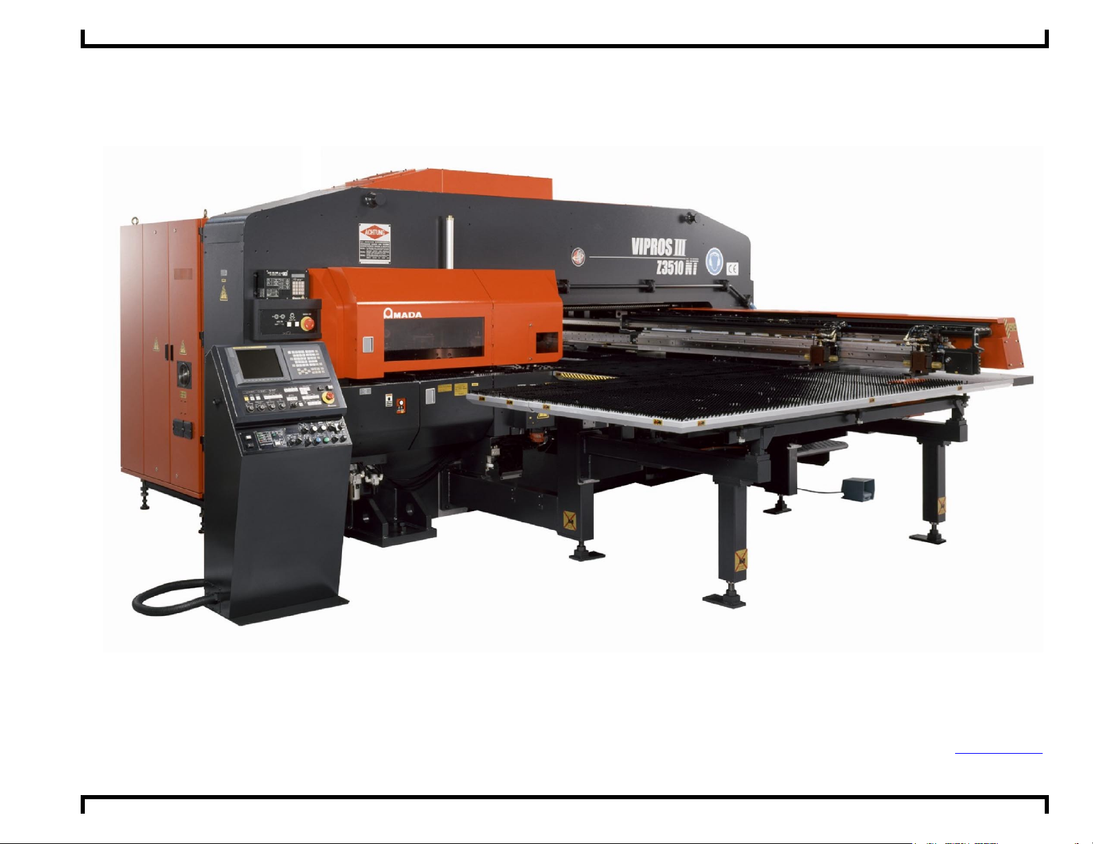
Vipros III Z/K3610NT with AMNC-F Control
Layout Drawings
Amada America Inc.
7025 Firestone Blvd.
Buena Park CA. 90621
Fax.: (714) 739 4099
Email info@amada.com
Print Date 08/11/2004 Revision 2 This document available on the World Wide Web at http://www.amada.com/ Page 1 of 13
Page 2
Vipros III Z/K 3610NT Layout Drawings ©Amada America Inc.
Warning
XQualified personnel must complete all work.
XDo not apply power to the Vipros III 3610NT until an Amada Service Engineer is present and has instructed you
to do so.
XNot all information required to install the Vipros lll Z/K 3610 NT is included with this document. Specific details for
proper installation are found in the document Vipros lll Z/K 3610 NT with AMNC-F User Pre-installation Guide
available at the Amada America Internet web site at http://www.amada.com/.
XConsiderable effort has been made to ensure that this manual is free of inaccuracies and omissions. However,
as we are constantly improving our product, some of the data contained herein may be out of date. Please
check our Internet site, http://www.amada.com/, for the latest release of this document.
Print Date 08/11/2004 Revision 2 This document available on the World Wide Web at http://www.amada.com/ Page 2 of 13
Page 3
Vipros III Z/K 3610NT Layout Drawings ©Amada America Inc.
Contents
Planning the Location of the Vipros lll Z/K 3610 NT .......................................................................................... 4
Plan View - Vipros lll Z/K 3610 NT .................................................................................................................... 5
Plan View - Vipros lll Z/K 3610 NT (shown with MP1530 Loader) ..................................................................... 6
Detailed Plan View - Vipros lll Z/K 3610 NT ...................................................................................................... 7
Elevation View - Vipros lll Z/K 3610 NT............................................................................................................. 8
End View - Vipros lll Z/K 3610 NT ..................................................................................................................... 9
Conveyor Options – Single Steel Track Conveyor........................................................................................... 10
Conveyor Options – Rubber Belt Dual Conveyor.............................................................................................11
Conveyor Options – “Generic” Dual Rubber Belt Conveyor............................................................................. 12
Chiller Placement ............................................................................................................................................ 13
Print Date 08/11/2004 Revision 2 This document available on the World Wide Web at http://www.amada.com/ Page 3 of 13
Page 4

Vipros III Z/K 3610NT Layout Drawings ©Amada America Inc.
Planning the Location of the Vipros lll Z/K 3610 NT
The following diagrams provide the details for positioning the Vipros lll Z/K 3610 NT.
YNo obstacles are allowed in the worksheet travel area and the ceiling must be at least 40" above the Vipros lll Z/K 3610 NT.
YAll of the recommended maintenance areas should be used, but at a minimum the doors of the NC unit must be able to be
opened. Any reduction of the listed maintenance areas may increase time and expense of installation and maintenance.
YThe Vipros lll Z/K 3610 NT machine and control must be protected from direct sunlight or other heat sources. Direct exposure
to direct heating sources such as infrared heaters have been shown to affect punch and die alignment.
YThe positioning of the SBC EX5.5 Chiller is very flexible.
Print Date 08/11/2004 Revision 2 This document available on the World Wide Web at http://www.amada.com/ Page 4 of 13
Page 5

Vipros III Z/K 3610NT Layout Drawings ©Amada America Inc.
Plan View - Vipros lll Z/K 3610 NT
Electrical Requirements
Vipros III Z/K 3610NT
200/ 3 / 60 ±10%, 30 kVA
E1
86 amps @ 200VAC / 3phase / 60 hz.
To operate at 230 / 460 VAC a step up
transformer is required.
SBC EX5.5 Chiller
E2
230 or 460 / 3 / 60 ±10% 15 kVA
19 amps @ 460 / 3 / 60 VAC
Compressed Air Requirements
Vipros III K 3610NT
A1
Vipros III Z 3610NT
Operator Control Station
80 psi @ 8.8 ft3/min.
80 psi @ 19 ft3/min.
12" 12" 12"
Scale
37"
Y-axis 0"
57"
Chiller Unit
(Actual location variable)
E2
Optional Material
Support Required
Track 200
Punch Center
213.5" Machine length
120" Maximum travel area 60" material
Optional Material
333" Recommended Safety / Maintenance area 40" from all components
Support Required
E1
Machine
202" Machine Width
393.70" Maximum Travel Area when punching 196.85" Material*
474" Recomended Safety / Maintenance Area 40" from all components*
* Actual clearance depends on the maximum size of the material that will be punched
- Always use sub tables to support sheets larger than 100"
P1
Centerline
98.425" to X axis origin
101" to edge of table
Print Date 08/11/2004 Revision 2 This document available on the World Wide Web at http://www.amada.com/ Page 5 of 13
Page 6

Vipros III Z/K 3610NT Layout Drawings ©Amada America Inc.
Plan View - Vipros lll Z/K 3610 NT (shown with MP1530 Loader)
Electrical Requirements
Vipros III Z/K 3610NT
200/ 3 / 60 ±10%, 30 kVA
E1
86 amps @ 200VAC / 3phase / 60 hz.
To operate at 230 / 460 VAC a step up
transformer is required.
SBC EX5.5 Chiller
E2
230 or 460 / 3 / 60 ±10% 15 kVA
19 amps @ 460 / 3 / 60 VAC
37 amps @ 230 / 3 / 60 VAC
MP1530 Loader
E5
200 / 3 / 60 ±10%, 10 Kva
To operate at 230 / 460 VAC a step up
transformer is required.
Compressed Air Requirements
Vipros III K 3610NT
A1
Vipros III Z 3610NT
MP1530 Loader
A2
Operator Control Station
80 psi @ 8.8 ft3/min.
80 psi @ 19 ft3/min.
80 psi @ 31.8 ft³/min.
12" 12" 12"
213.5" Machine length
Scale
Y-axis 0"
Track 200
Punch Center
37"
57"
Chiller Unit
(Actual location variable)
E2
A2
MP1530
E5
Xformer
145.8" 78.0"
223.8" MP1530 Loader Length
120" Maximum travel area 60" material
Optional Material
333" Recommended Safety / Maintenance area 40" from all components
Support Required
E1
A1
MP1530
Access Required For Material / Parts Removal
Machine
Centerline
98.425" to X axis origin
101" to edge of table
202" Machine Width
393.70" Maximum Travel Area when punching 196.85" Material*
538" Recommended Safety / Maintenance Area 40" From All Components*
* Actual clearance depends on the maximum size of the material that will be punched
- Always use sub tables to support sheets larger than 100"
102" to edge of loader
162.7" MP1530 Loader Width
Print Date 08/11/2004 Revision 2 This document available on the World Wide Web at http://www.amada.com/ Page 6 of 13
Page 7

Vipros III Z/K 3610NT Layout Drawings ©Amada America Inc.
Detailed Plan View - Vipros lll Z/K 3610 NT
Y ZERO DATUM POINT
9.33"
40.55"
47.24"
3.15"
18.90"
19.69"
60.36" 60.08"
42.24"
21.77"
100.79"
19.69"
CONTROL
118.07"CONTROL MOVABLE RADIUS
90.95"
19.69"
26.34"
89.37"
Print Date 08/11/2004 Revision 2 This document available on the World Wide Web at http://www.amada.com/ Page 7 of 13
124.10"
PUNCH CENTERLINE
2.36" X ZERO DATUM POINT
98.43"
100.79"
201.58"
Page 8

Vipros III Z/K 3610NT Layout Drawings ©Amada America Inc.
Elevation View - Vipros lll Z/K 3610 NT
Punch Center track 200
Y axis zero datum point
61.02"
26.77"
84.25"
62.60"
Throat Depth
8.46"
23.62"
60.04"
6.89"
18.90"
35.24"
19.69"
9.13"
5.91"
98.03"
43.31" ** 48.82"
1.26" **
15.75"
113.62"
38.98"
213.47" ( 240.5" for shipping*)
* Electrical Cabinet is attached to left side of
frame for shipping adding 27" to overall length
**
Material Pass line may vary due to installation of different options
Print Date 08/11/2004 Revision 2 This document available on the World Wide Web at http://www.amada.com/ Page 8 of 13
129.33"
15.75"
45.16"
Page 9

Vipros III Z/K 3610NT Layout Drawings ©Amada America Inc.
End View - Vipros lll Z/K 3610 NT
21.81"
32.92"
42.05"
41.34"
125.20" (Shipping width)
Print Date 08/11/2004 Revision 2 This document available on the World Wide Web at http://www.amada.com/ Page 9 of 13
1.25"
Page 10

Vipros III Z/K 3610NT Layout Drawings ©Amada America Inc.
Conveyor Options – Single Steel Track Conveyor
TOP VIEW
14.21"
SIDE VIEW
65.01"
43.12"
Print Date 08/11/2004 Revision 2 This document available on the World Wide Web at http://www.amada.com/ Page 10 of 13
Page 11

Vipros III Z/K 3610NT Layout Drawings ©Amada America Inc.
Conveyor Options – Rubber Belt Dual Conveyor
135.3"
27.6"
71"
44"
148"
60.5"
Print Date 08/11/2004 Revision 2 This document available on the World Wide Web at http://www.amada.com/ Page 11 of 13
Page 12

Vipros III Z/K 3610NT Layout Drawings ©Amada America Inc.
Conveyor Options – “Generic” Dual Rubber Belt Conveyor
Conveyor
Outlet
30.80"
113.6"
Print Date 08/11/2004 Revision 2 This document available on the World Wide Web at http://www.amada.com/ Page 12 of 13
Page 13

Vipros III Z/K 3610NT Layout Drawings ©Amada America Inc.
Chiller Placement
Two 15ft supplied water lines
6"
Chiller Unit
Air Flow
Under normal operating conditions the Chiller may be placed against walls as shown.
For maintenance purposes access to all sides may be required.
60" overhead clearence required.
Chiller may be located up to 50ft from Hydraulic Unit.
Chiller is not designed for outdoor placement.
Print Date 08/11/2004 Revision 2 This document available on the World Wide Web at http://www.amada.com/ Page 13 of 13
6"
 Loading...