

Page 1

REFERENCE MANUAL
CNC LASER MACHINE
AMNC-F
AMNC-F-LASER-E02-200710
Page 2

PREFACE Read this manual carefully to obtain a thorough knowledge of the AMNC-F for the laser machine.
Be sure to follow the instructions to ensure proper procedures and prevent injuries and accidents. Do not operate
the AMNC-F by guesswork. Keep the manual at hand
and refer to it whenever you are not sure of how to
perform any of the procedures.
For the operation and maintenance of the laser machine,
refer to its own operator’s manual.
200709010504
Reference Manual:
AMNC-F
© 2007 by AMADA CO., LTD.
No part of this publication may be photocopied or otherwise reproduced without the prior written permission of AMADA CO., LTD.
ii
Printed in Japan
Page 3

CONTENTS
Part I Displays................................................................................ I-1
1. Description ............................................................................. I-4
1-1. Description of display operation...................................... I-4
1-1-1. Basic operation......................................................... I-4
1-1-2. Entering letters and numerals .................................. I-4
1-1-3. Scroll bars ................................................................ I-4
1-1-4. Cursor....................................................................... I-4
1-2. Composition of displays .................................................. I-5
2. Areas common to displays ..................................................... I-9
2-1. Processing status display area 1 .................................... I-9
2-2. Processing status display area 2 ................................... I-18
2-3. Data edit area................................................................. I-20
2-4. Status icons.................................................................... I-43
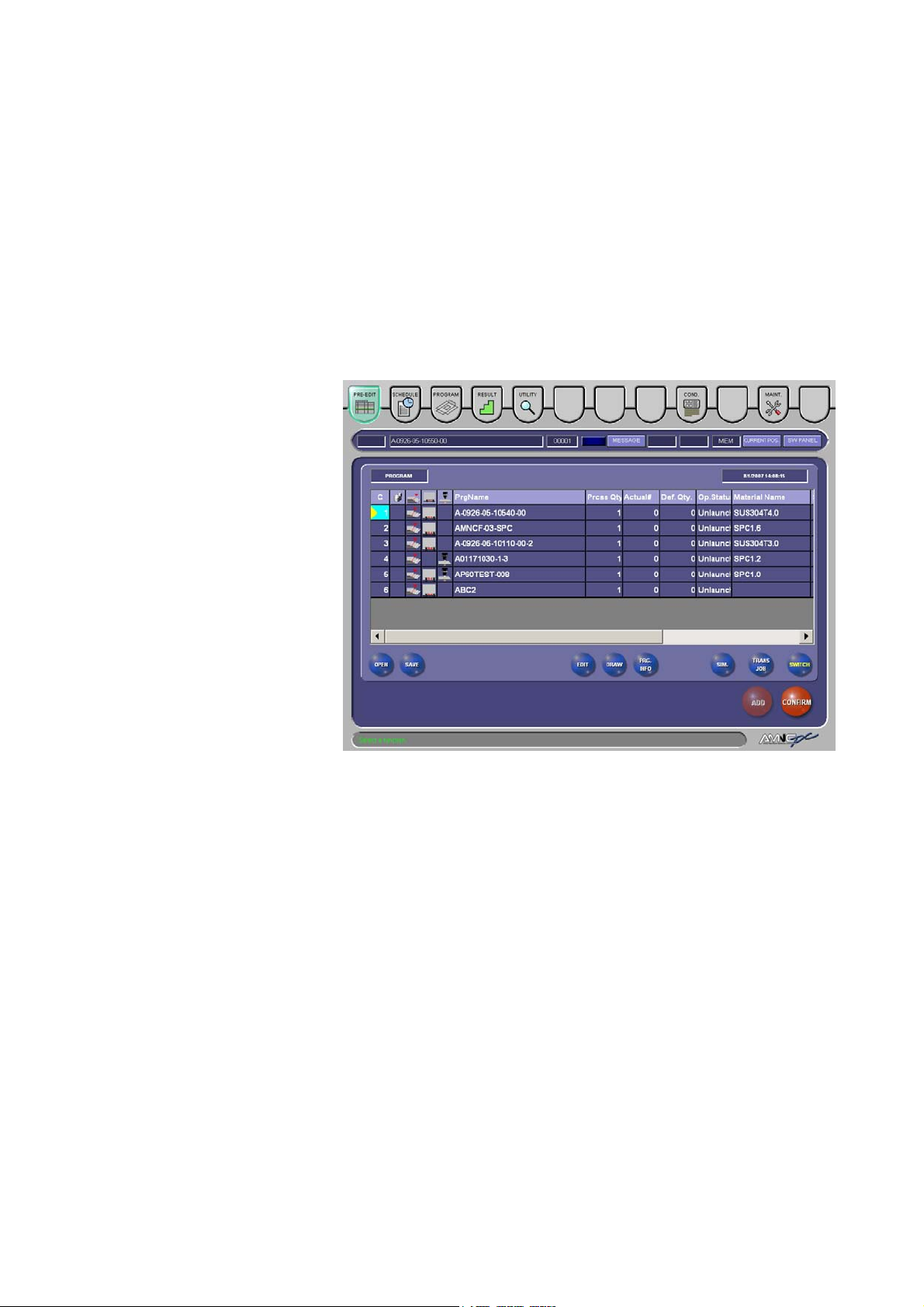
3. PRE-EDIT display (background)........................................... I-44
3-1. Creating program from PRE-EDIT display..................... I-44
3-2. Calling program from PRE-EDIT display ....................... I-45
3-3. Saving program from PRE-EDIT display ....................... I-47
3-4. Transferring job to PROGRAM display .......................... I-47
3-5. Transferring selected job................................................ I-48
3-6. Transferring schedule to SCHEDULE display................ I-48
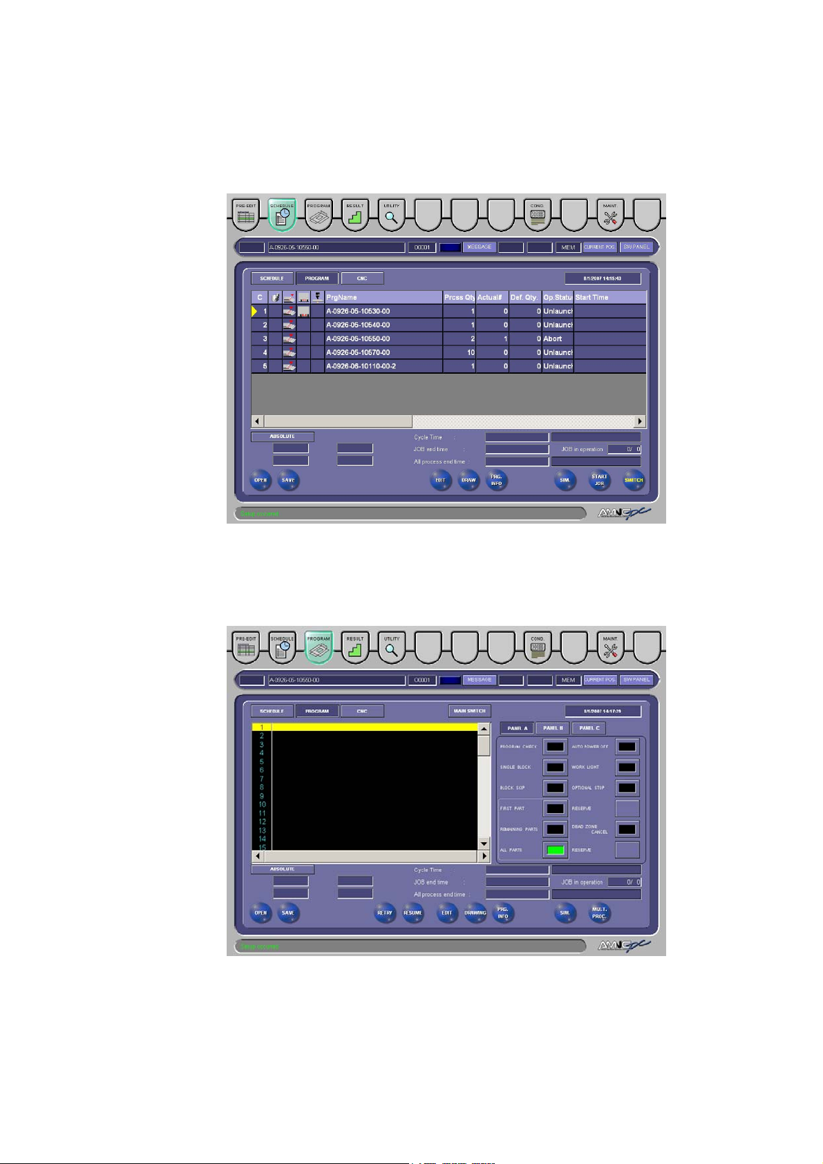
4. SCHEDULE display .............................................................. I-49
4-1. Creating program from SCHEDULE display .................. I-50
4-2. Calling program from SCHEDULE display..................... I-50
4-3. Saving program from SCHEDULE display..................... I-52
4-4. Selecting start job........................................................... I-52
5. PROGRAM display ............................................................... I-53
5-1. Creating program from PROGRAM display................... I-54
5-2. Calling program from PROGRAM display...................... I-54
5-3. Saving program from PROGRAM display...................... I-55
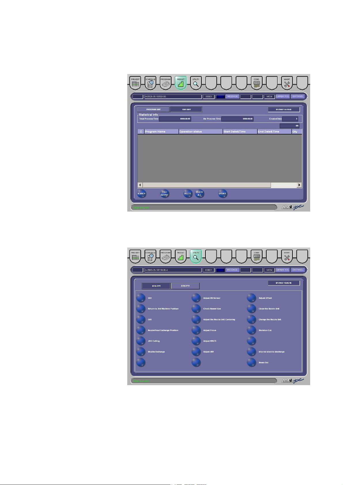
6. RESULT display.................................................................... I-56
7. UTILITY display .................................................................... I-60
7-1. G50 ................................................................................ I-61
7-2. Return to 2nd
7-3. G00 ................................................................................ I-63
7-4. Nozzle/Head Exchange Position.................................... I-64
Machine Position ..................................... I-62
(Continued on next page.)
iii
Page 4

7-5. JOG Cutting ....................................................................I-66
7-6. Shuttle Exchange............................................................I-68
7-7. Adjust HS Sensor............................................................I-69
7-8. Check Assist Gas............................................................I-70
7-9. Adjust the Nozzle Unit Centering ....................................I-72
7-10. Adjust Focus .................................................................I-74
7-11. Adjust WACS.................................................................I-78
7-12. Adjust AIV......................................................................I-79
7-13. Adjust Offset..................................................................I-80
7-14. Internal electric discharge.............................................I-82
7-15. Beam-Out......................................................................I-83
7-16. Clean the Nozzle Unit ...................................................I-84
7-17. Skeleton Cut .................................................................I-85
7-18. Settings .........................................................................I-88
7-19. Input error .....................................................................I-89
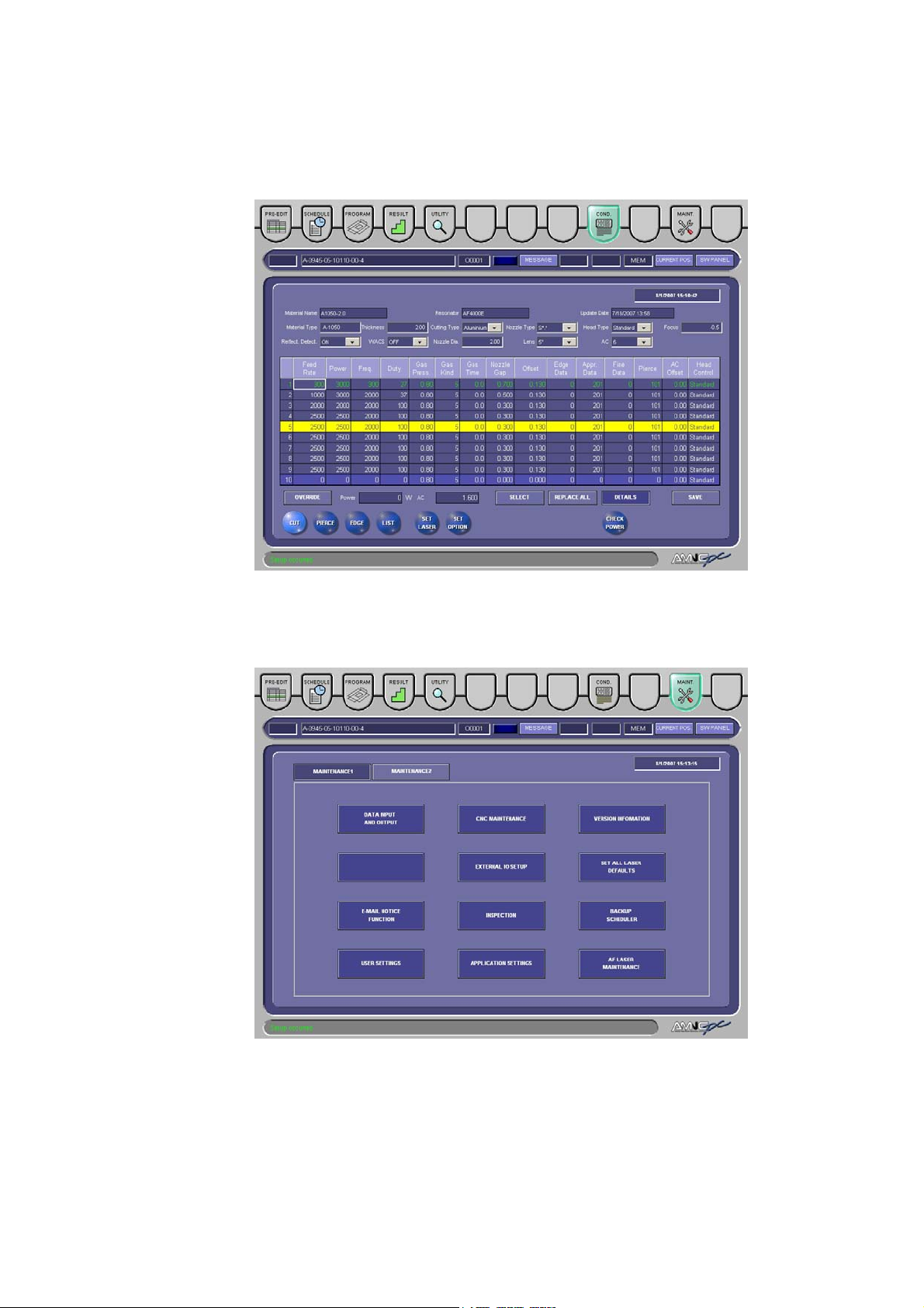
8. Processing condition displays ...............................................I-90
8-1. Common areas of processing condition displays ...........I-91
8-1-1. Common area 1 .......................................................I-91
8-1-2. Common area 2 .......................................................I-93
8-1-3. Common area setting operations.............................I-95
8-2. CUT display................................................................... I-101
8-2-1. Output Check display ............................................. I-103
8-3. PIERCE display ............................................................ I-104
8-4. EDGE display................................................................ I-107
8-5. LIST display ...................................................................I-110
8-5-1. Calling processing conditions..................................I-111
8-5-2. Finding processing conditions.................................I-111
8-5-3. Copying processing conditions ...............................I-113
8-5-4. Changing material name.........................................I-113
8-5-5. Deleting processing conditions ...............................I-114
8-5-6. Exporting processing conditions .............................I-115
8-5-7. Importing processing conditions .............................I-115
8-5-8. Exporting all processing conditions at a time..........I-116
8-5-9. Importing all processing conditions at a time ..........I-117
8-6. SET LASER display .......................................................I-118
8-6-1. LASER PRM display ...............................................I-118
8-6-2. AIV display ............................................................. I-121
8-6-3. HS EDGE display................................................... I-124
8-6-4. PROBE display ...................................................... I-126
8-7. SET OPTION displays .................................................. I-128
8-8. DETAIL OFF display ..................................................... I-129
iv
Page 5

8-8-1. COND. display........................................................ I-130
8-8-2. LIST display............................................................ I-130
8-8-3. SET LASER display ............................................... I-130
9. Maintenance display ............................................................ I-131
9-1. DATA INPUT AND OUTPUT ......................................... I-132
9-1-1. Copying data .......................................................... I-133
9-1-2. Moving data............................................................ I-134
9-2. CNC MAINTENANCE ................................................... I-135
9-2-1. Reading O number................................................. I-136
9-2-2. Writing O number ................................................... I-136
9-3. VERSION INFORMATION ............................................ I-142
9-4. EXTERNAL IO SETUP ................................................. I-143
9-5. SET ALL LASER DEFAULTS........................................ I-144
9-6. E-MAIL NOTICE FUNCTION........................................ I-145
9-6-1. Details of Setup of E-mail Notice display ............... I-146
9-6-2. Details of E-mail Notice Function display............... I-148
9-6-3. Details of E-mail Transmission display................... I-149
9-7. INSPECTION ................................................................ I-153
9-7-1. INSPECTION ......................................................... I-153
9-7-2. TASK ...................................................................... I-155
9-7-3. ADD ITEM .............................................................. I-156
9-7-4. NOTICE.................................................................. I-157
9-7-5. HOLIDAY................................................................ I-158
9-7-6. SETTING................................................................ I-159
9-7-7. CALENDAR............................................................ I-160
9-8. BACKUP SCHEDULER ................................................ I-161
9-9. USER SETTINGS ......................................................... I-164
9-10. APPLICATION SETTINGS.......................................... I-171
9-11. AF LASER MAINTENANCE ........................................ I-172
9-12. M LASER MAINTENANCE ......................................... I-179
Part II Program Management........................................................ II-1
1. Creating program................................................................... II-3
1-1. Creating program from PRE-EDIT or
SCHEDULE display ........................................................II-3
1-2. Creating program from PROGRAM display.................... II-6
2. Calling program......................................................................II-9
2-1. Calling program from PRE-EDIT or
SCHEDULE display ........................................................II-9
(Continued on next page.)
v
Page 6

2-2. Calling program from PRE-EDIT or
PROGRAM display ........................................................ II-12
3. Saving program ....................................................................II-14
3-1. Saving program from PRE-EDIT or
SCHEDULE display ....................................................... II-14
3-2. Saving program from PROGRAM display .....................II-17
4. Saving schedule ...................................................................II-20
5. Moving program.................................................................... II-22
6. Copying program .................................................................. II-25
7. Deleting program .................................................................. II-28
8. Editing program ....................................................................II-30
8-1. Searching for word......................................................... II-30
8-2. Replacing word .............................................................. II-32
8-3. Copying and pasting word ............................................. II-35
8-4. Setting multiple-part processing..................................... II-37
8-4-1. Calling program from PRE-EDIT or
SCHEDULE display ................................................II-39
8-4-2. Calling program from PROGRAM display............... II-41
8-4-3. Calling program from Edit display ........................... II-42
8-4-4. Example of use of Multi display............................... II-44
8-4-5. Coping inability to correct on Multi display.............. II-46
8-4-6. Changing program codes........................................ II-47
8-4-7. End position command R........................................ II-47
8-4-8. Examples of operation ............................................II-47
9. Searching for program.......................................................... II-54
9-1. Searching for program from Open display..................... II-54
9-2. Searching for program from Data input and
output display................................................................. II-56
10. Schedule Operation............................................................II-58
10-1. Creating schedule ........................................................II-58
10-2. Copying and pasting schedule..................................... II-61
10-3. Deleting schedule job................................................... II-63
10-4. Deleting all schedule jobs ............................................ II-64
11. Setting up............................................................................ II-66
11-1. Schedule operation ...................................................... II-66
11-2. Program operation .......................................................II-68
12. Editing processing conditions .............................................II-69
12-1. Calling processing conditions ...................................... II-69
12-2. Editing processing conditions ...................................... II-70
12-3. Saving processing conditions ...................................... II-71
13. Types of floppy disks ..........................................................II-72
vi
Page 7

Part III NC Codes ...........................................................................III-1
1. Description of program ......................................................... III-4
1-1. Block .............................................................................. III-4
1-2. Word............................................................................... III-4
1-3. Composition of program................................................. III-4
1-4. Main program and subprogram...................................... III-6
2. G-codes ................................................................................ III-7
2-1. Positioning (G00) ........................................................... III-9
2-2. Linear interpolation (G01) .............................................. III-9
2-3. Circular interpolation (G02, G03) .................................. III-10
2-4. Dwell (G04) ................................................................... III-11
2-5. Exact stop (G09, G61, G64) ......................................... III-11
2-6. Unloading (G10)............................................................ III-12
2-7. Piercing mode (G24)..................................................... III-12
2-8. Auto-repositioning (G25, G27) ...................................... III-12
2-9. Assist gas selection (G31) ............................................ III-14
2-10. Z-axis tracking (G32, G33).......................................... III-14
2-11. Laser beam path compensation (G40, G41, G42)...... III-15
2-12. Automatic zero return and operation end
(G50, G130) ................................................................ III-18
2-13. Regular-shaped hole macros...................................... III-19
2-13-1. Single-hole cutting (G111 to G116) ...................... III-20
2-13-2. Shape registration and continuous-hole cutting... III-25
2-13-3. Shape registration and pattern cutting
(G126, G128, G129, G136, G137)....................... III-26
2-14. Absolute and incremental programming (G90, G91).. III-30
2-15. Coordinate system setup (G92) .................................. III-31
2-16. Offset origin setup (G93)............................................. III-32
2-17. Multiple-part processing (G75, G76, G98).................. III-33
2-17-1. Multiple-part processing reference point and
part spacing setup................................................ III-34
2-17-2. Macro store .......................................................... III-34
2-17-3. Multiple-part processing commands
(G75, G76) ........................................................... III-35
2-17-4. Program examples ............................................... III-36
2-18. HS edge detection (G121, G122) ............................... III-37
2-18-1. HS edge detection calibration (G122) .................. III-38
2-18-2. Compensation by edge measurement
(G121 L1 to L5).................................................... III-41
2-18-3. Fine adjustment of measurement error ................ III-58
(Continued on next page.)
vii
Page 8

2-19. OVS (G140, G141, G149) ...........................................III-60
2-20. Scaling and coordinate rotation (G150) .......................III-79
2-21. Pipe cutting NC-codes (G08, G17, G18, G107) ..........III-80
2-21-1. NC-code restrictions and cautions ........................III-81
2-21-2. Program example..................................................III-82
3. M-codes ................................................................................III-83
3-1. Operation stop (M00, M01)............................................III-85
3-2. End processing (M02, M30)...........................................III-85
3-3. Repositioning (M10, M11) ..............................................III-85
3-4. Worksheet thickness detection range (M20 to M29) .....III-86
3-5. Loading (M33)................................................................III-86
3-6. Two-stack unloading (M65)............................................III-86
3-7. Workchute (M80, M81, M180) .......................................III-87
3-8. Subprogram call (M96) ..................................................III-87
3-9. Subprogram end (M97)..................................................III-87
3-10. Processing mode (M100, M101)..................................III-88
3-11. Worksheet designation (M102) ....................................III-88
3-12. Laser cutting (M103, M104).........................................III-89
3-13. Shuttle pallet change (M707).......................................III-90
3-14. Z-axis tracking sensor calibration
(M722, M723, M727)..................................................III-90
3-15. Beam on and off (M758) ..............................................III-90
3-16. Shuttle move to cleaning position (M788, M789).........III-91
3-17. Pallet set (M790, M791)...............................................III-91
3-18. Pallet pins (M792, M793).............................................III-91
4. Other codes ..........................................................................III-92
4-1. Cutting condition (E-code) .............................................III-92
4-2. Sequence number (N-code) ..........................................III-97
4-3. Skip command (GOTO-code) ........................................III-92
4-4. Workchute (M80, M81, M180) .......................................III-93
4-5. Macro store command (U- and V-codes).......................III-93
viii
Page 9

Part I
Displays
1. Description ...................................................................................I-4
1-1. Description of display operation............................................I-4
1-1-1. Basic operation...............................................................I-4
1-1-2. Entering letters and numerals ........................................I-4
1-1-3. Scroll bars ......................................................................I-4
1-1-4. Cursor.............................................................................I-4
1-2. Composition of displays ........................................................I-5
2. Areas common to displays ...........................................................I-9
2-1. Processing status display area 1 ..........................................I-9
2-2. Processing status display area 2 .........................................I-18
2-3. Data edit area.......................................................................I-20
2-4. Status icons..........................................................................I-43
3. PRE-EDIT display (background).................................................I-44
3-1. Creating program from PRE-EDIT display...........................I-44
3-2. Calling program from PRE-EDIT display..............................I-45
3-3. Saving program from PRE-EDIT display..............................I-47
3-4. Transferring job to PROGRAM display ................................I-47
3-5. Transferring selected job......................................................I-48
3-6. Transferring schedule to SCHEDULE display......................I-48
4. SCHEDULE display ....................................................................I-49
4-1. Creating program from SCHEDULE display ........................I-50
4-2. Calling program from SCHEDULE display...........................I-50
4-3. Saving program from SCHEDULE display...........................I-52
(Continued on next page.)
I-1
Page 10

4-4. Selecting start job ................................................................I-52
5. PROGRAM display .....................................................................I-53
5-1. Creating program from PROGRAM display.........................I-54
5-2. Calling program from PROGRAM display ...........................I-54
5-3. Saving program from PROGRAM display ...........................I-55
6. RESULT display.......................................................................... I-56
7. UTILITY display .......................................................................... I-60
7-1. G50 ......................................................................................I-61
7-2. Return to 2nd
Machine Position ...........................................I-62
7-3. G00 ......................................................................................I-63
7-4. Nozzle/Head Exchange Position..........................................I-64
7-5. JOG Cutting .........................................................................I-66
7-6. Shuttle Exchange.................................................................I-68
7-7. Adjust HS Sensor.................................................................I-69
7-8. Check Assist Gas.................................................................I-70
7-9. Adjust the Nozzle Unit Centering .........................................I-72
7-10. Adjust Focus ......................................................................I-74
7-11. Adjust WACS......................................................................I-78
7-12. Adjust AIV...........................................................................I-79
7-13. Adjust Offset.......................................................................I-80
7-14. Internal electric discharge ..................................................I-82
7-15. Beam-Out...........................................................................I-83
7-16. Clean the Nozzle Unit ........................................................I-84
7-17. Skeleton Cut ......................................................................I-85
7-18. Settings ..............................................................................I-88
7-19. Input error ..........................................................................I-89
8. Processing condition displays.....................................................I-90
8-1. Common areas of processing condition displays ................I-91
8-1-1. Common area 1 ............................................................I-91
8-1-2. Common area 2 ............................................................I-93
8-1-3. Common area setting operations.................................. I-95
8-2. CUT display.........................................................................I-101
8-2-1. Output Check display ...................................................I-103
8-3. PIERCE display ..................................................................I-104
8-4. EDGE display......................................................................I-107
8-5. LIST display ........................................................................I-110
8-5-1. Calling processing conditions....................................... I-111
8-5-2. Finding processing conditions...................................... I-111
8-5-3. Copying processing conditions ....................................I-113
8-5-4. Changing material name ..............................................I-113
8-5-5. Deleting processing conditions ....................................I-114
I-2
Page 11

8-5-6. Exporting processing conditions ..................................I-115
8-5-7. Importing processing conditions...................................I-115
8-5-8. Exporting all processing conditions at a time ...............I-116
8-5-9. Importing all processing conditions at a time ...............I-117
8-6. SET LASER display ............................................................I-118
8-6-1. LASER PRM display ....................................................I-118
8-6-2. AIV display....................................................................I-121
8-6-3. HS EDGE display .........................................................I-124
8-6-4. PROBE display.............................................................I-126
8-7. SET OPTION displays ........................................................I-128
8-8. DETAIL OFF display............................................................I-129
8-8-1. COND. display..............................................................I-130
8-8-2. LIST display..................................................................I-130
8-8-3. SET LASER display .....................................................I-130
9. Maintenance display ..................................................................I-131
9-1. DATA INPUT AND OUTPUT ...............................................I-132
9-1-1. Copying data ................................................................I-133
9-1-2. Moving data..................................................................I-134
9-2. CNC MAINTENANCE .........................................................I-135
9-2-1. Reading O number .......................................................I-136
9-2-2. Writing O number .........................................................I-136
9-3. VERSION INFORMATION ..................................................I-142
9-4. EXTERNAL IO SETUP........................................................I-143
9-5. SET ALL LASER DEFAULTS ..............................................I-144
9-6. E-MAIL NOTICE FUNCTION..............................................I-145
9-6-1. Details of Setup of E-mail Notice display .....................I-146
9-6-2. Details of E-mail Notice Function display.....................I-148
9-6-3. Details of E-mail Transmission display.........................I-149
9-7. INSPECTION ......................................................................I-153
9-7-1. INSPECTION ...............................................................I-153
9-7-2. TASK ............................................................................I-155
9-7-3. ADD ITEM ....................................................................I-156
9-7-4. NOTICE........................................................................I-157
9-7-5. HOLIDAY......................................................................I-158
9-7-6. SETTING......................................................................I-159
9-7-7. CALENDAR..................................................................I-160
9-8. BACKUP SCHEDULER ......................................................I-161
9-9. USER SETTINGS ...............................................................I-164
9-10. APPLICATION SETTINGS................................................I-171
9-11. AF LASER MAINTENANCE ..............................................I-172
9-12. M LASER MAINTENANCE ...............................................I-179
I-3
Page 12

1. DESCRIPTION
1-1. Description of display operation
1-1-1. BASIC OPERATION
The machine has various buttons arranged on each display. The
buttons function when the corresponding portions on the display are
pressed or touched. Some of the buttons illuminate to indicate that
they are pressed.
1-1-2. ENTERING LETTERS AND NUMERALS
Use the accessory keyboard to enter or edit the letters and numerals on
each display.
1-1-3. SCROLL BARS
One or two scroll bars appear when all data cannot be shown on one
display as is the case with a file list. The display can also be scrolled
by pressing the scroll bar up and down buttons or moving up and down
the scroll bar lever.
1-1-4. CURSOR
When you touch the display position to which you want to move the
cursor, the cursor moves to that position.
If the display has cursor buttons, press the cursor buttons to move the
cursor to your desired position on the display.
The cursor moves also when the display is scrolled with the scroll bar
or bars.
I-4
Page 13
1-2. Composition of displays
There are eight displays: PRE-EDIT, SCHEDULE, PROGRAM,
RESULT, UTILITY, COND. (processing condition), and MAINT.
(maintenance). Press the corresponding button to change to each
display.
PRE-EDIT (background) button
Pressed to open the PRE-EDIT display to create and edit the next
program or schedule while the machine is operating. You can also
check the setup of the next program and check the part by drawing it
while the machine is operating.
I-5
Page 14
SCHEDULE button
Pressed to open the SCHEDULE display to read a schedule, create a
schedule, and set a start job or end job. You can also check the setup
and check the part by drawing it before operating the machine.
PROGRAM button
Pressed to open the PROGRAM display to show a program. You can
also check the setup and check the part by drawing it before operating
the machine.
I-6
Page 15
RESULT button
Pressed to open the RESULT display to show the actual processing
results.
UTILITY button
Pressed to open the UTILITY display to zero-return the machine’s axes
and make various adjustments.
I-7
Page 16
COND. button
Pressed to open the display to select and set the laser processing
conditions.
MAINT. button
Pressed to open the maintenance display to show maintenance items
and machine information.
I-8
Page 17
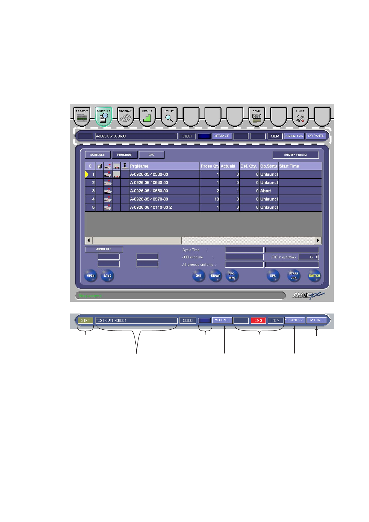
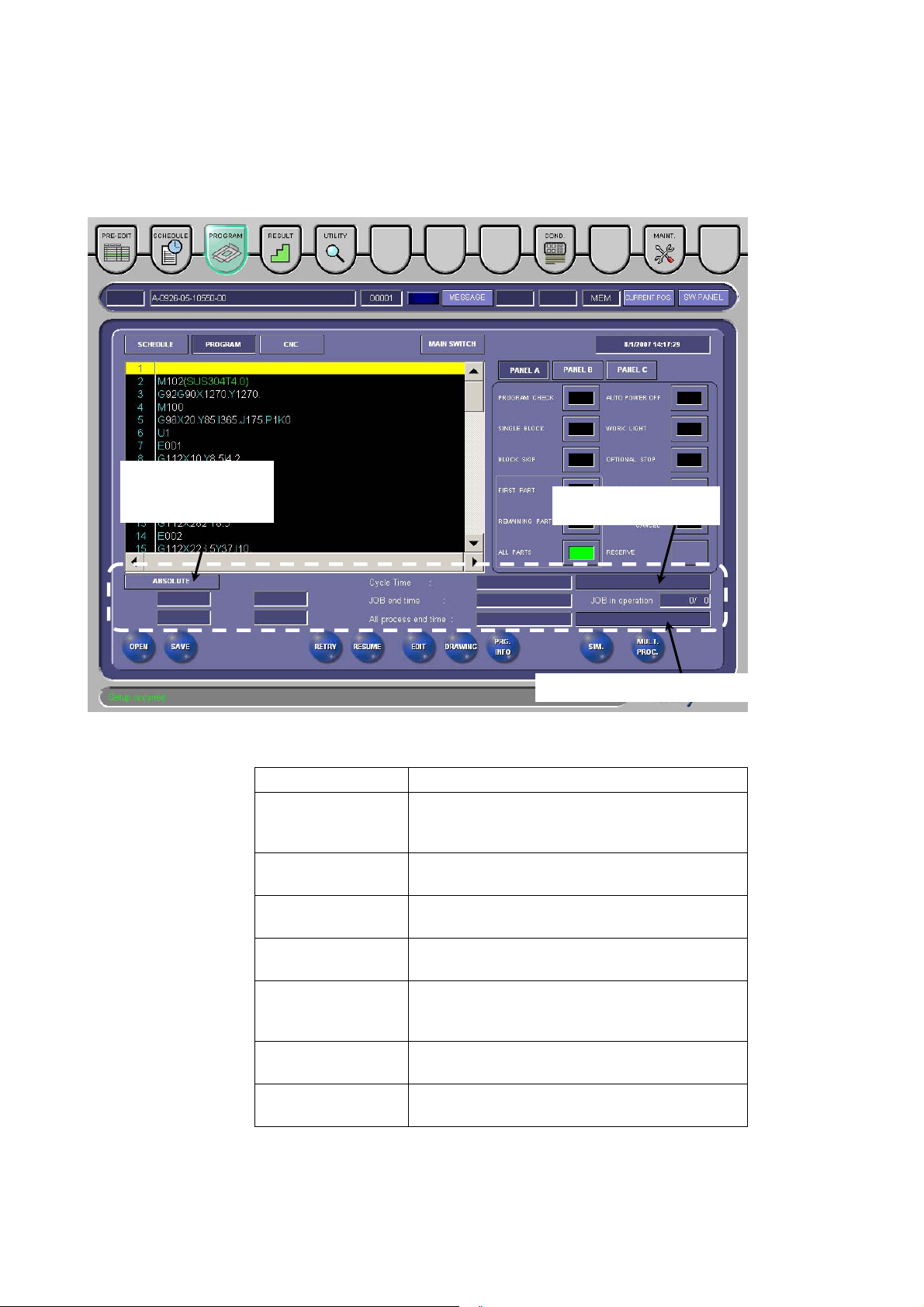
2. Areas common to displays
2-1. Processing status display area 1
Here are described the buttons and items on the common area of the
PRE-EDIT, SCHEDULE, and PROGRAM displays.
[4] PROCESSING
STATUS
DISPLAY FIELD
[5] RUNNING PROGRAM
DISPLAY FIELD
[6] OPERATION
STATUS
DISPLAY FIELD
[1] MESSAGE
BUTTON
[7] NC STATUS
DISPLAY FIELD
[2] CURRENT
POS. BUTTON
[3] SW. PANEL
BUTTON
I-9
Page 18
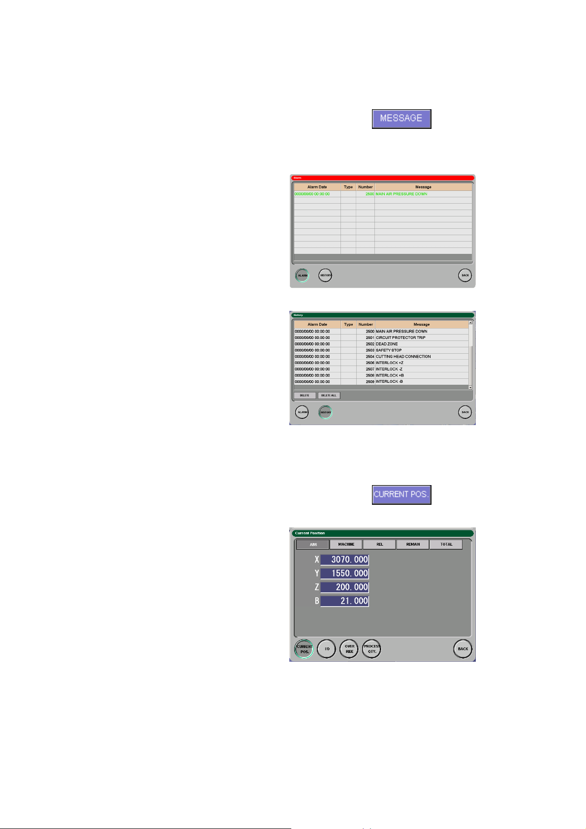
[1] MESSAGE button
Pressed to open the MESSAGE
display. When an alarm or warning
occurs, the MESSAGE display
automatically opens.
• Alarm display
Shows currently occurring
alarms or warnings.
• History display
Shows alarms or warnings
that have occurred to date.
[2] CURRENT POS. button
Pressed to open the Current Position
display.
• Current Position display
I-10
Page 19
Item Description
ABS button Shows the current positions in the work
coordinate system.
MACHINE button Shows the current positions in the machine
coordinate system.
REL button Shows the current positions in the relative
coordinate system.
Preset: Sets the selected axis to the specified
position.
Origin: Sets the relative coordinate position of
the selected axis to 0.
REMAIN button
Shows the remainder of the movement
commanded for one block in the MEMORY
mode.
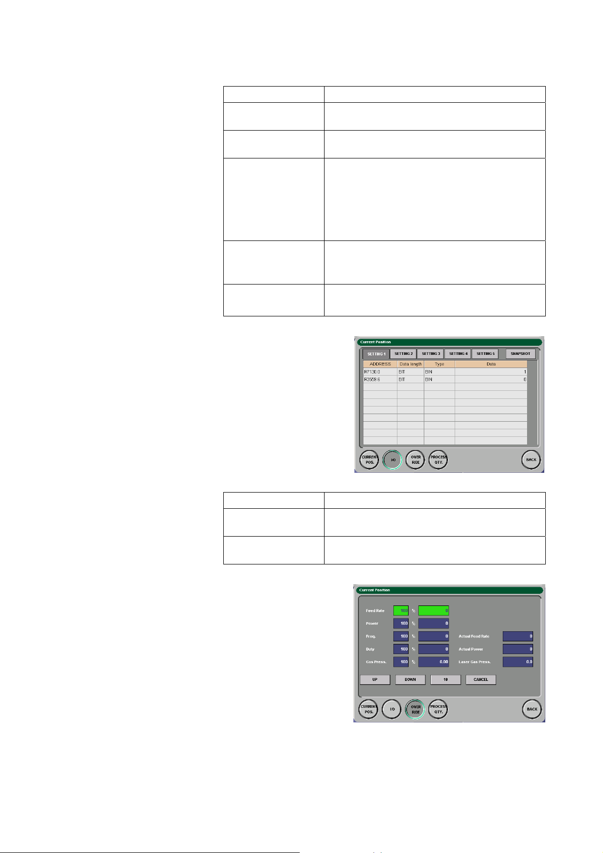
TOTAL button
• I/O display
Item Description
SETTING 1 to 5
buttons
SNAP SHOT button Saves the settings in the CSV format in a floppy
• Override display
Changes the override
(multiplication factor) to the
Feed Rate, Power, Freq.,
Duty, and Gas Press.
fields.
Shows the current position of each axis in all
coordinate systems.
Set 10 addresses per display or a total of 50
addresses.
disk.
I-11
Page 20
Item Description
UP button Increments the override by 10% (or 1%).
DOWN button Decrements the override by 10% (1%).
10 button
1 button
Changes the setting unit of the override
between 10% and 1%.
*The override is fixed at the unit of 10% for
duty.
CANCEL button Returns the override for the selected item to
100%.
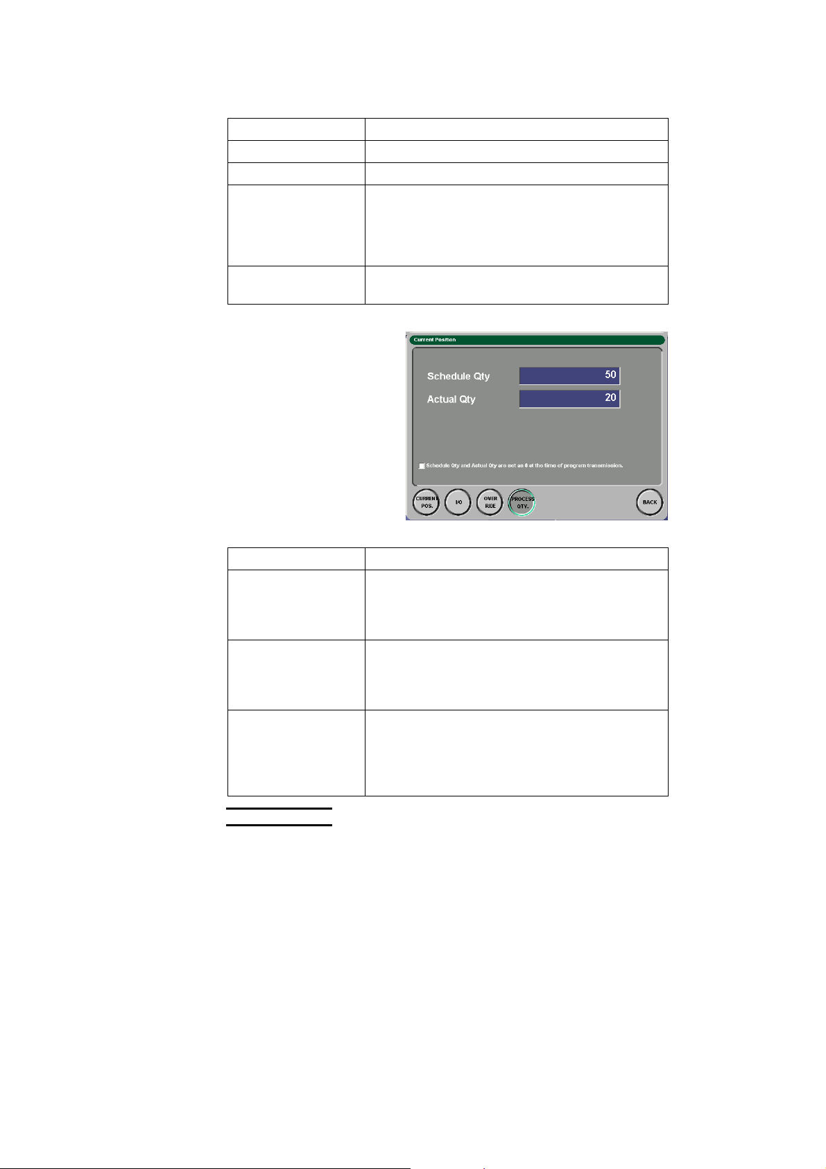
• Process quantity display
Shows the number of
worksheets to be
processed and the number
of worksheets already
processed.
Item Description
Schedule Qty field Shows the number of worksheets to be
processed. Enter a value, and press the
ENTER key. (The setting range is 0 to 9999
worksheets).
Actual Qty field Shows the number of worksheets already
processed. Enter a value, and press the
ENTER key. (The setting range is 0 to 9999
worksheets).
“Schedule Qty and
Actual Qty are set as
Checked to zero the Schedule Qty and Actual
Qty fields when the program is transferred.
0 at the time of
program
transmission” box
I-12
NOTE
O When the automatic operating mode is other than PROGRAM, the
PROCESS QTY. button is not shown.
Page 21
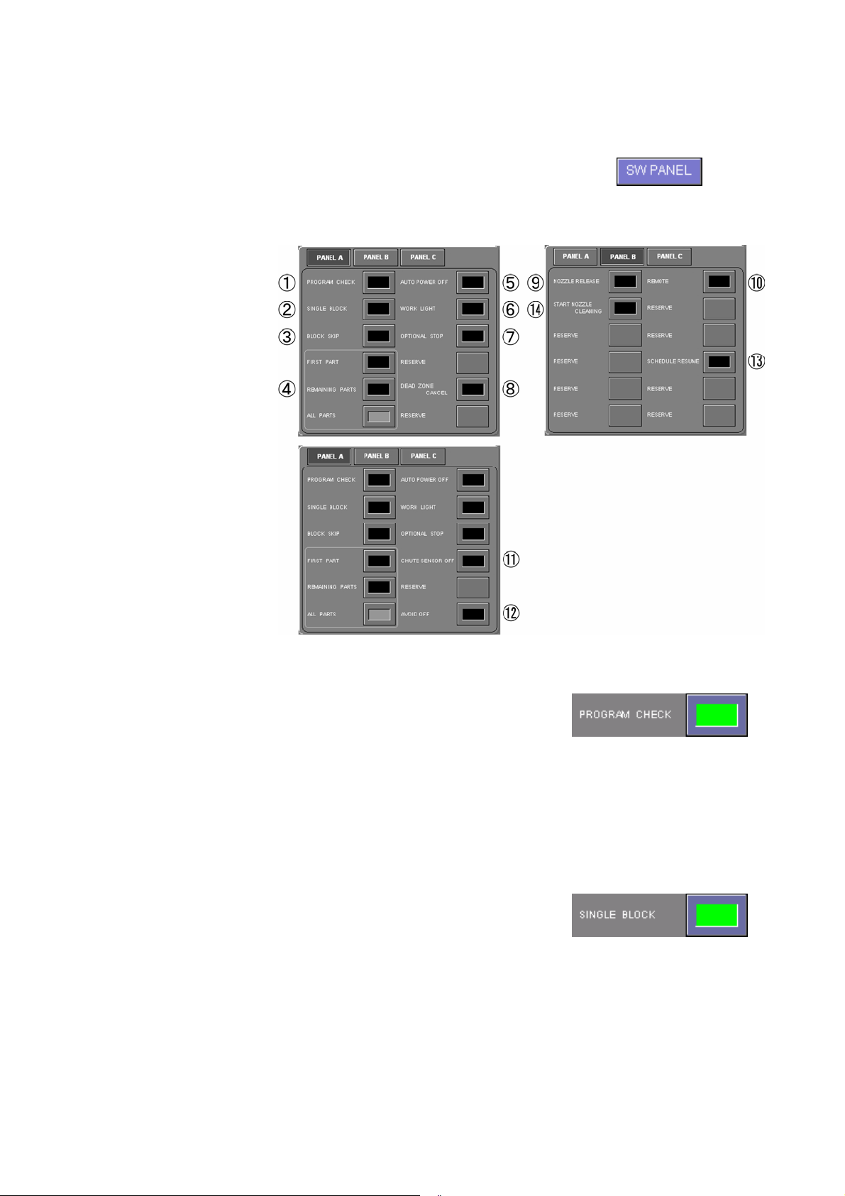
[3] SW PANEL button
Pressed to cycle through the
following panels with the buttons
required for the operation of the
machine.
◯1 PROGRAM CHECK button
Press the PROGRAM CHECK
button, and start the program. The
machine dry runs. During the dry
run, the coordinate values on the
display change, but the axes do not
move and the M-codes are not
executed. After the dry run, the
machine must be manually
zero-returned.
◯2 SINGLE BLOCK button
Press the SINGLE BLOCK button,
and then press the START button.
The machine executes one block of
the program and then stops.
I-13
Page 22
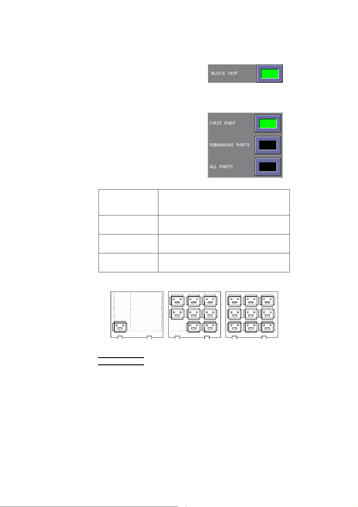
◯3 BLOCK SKIP button
Press the BLOCK SKIP button, and
then start the program. The
machine ignores each block with a
slash (/) at the beginning and goes
to the next block.
◯4 Multiple-part mode buttons
Press one of the multiple-part mode
buttons to select the multiple-part
processing function you want to
perform.
Do not use these buttons when the
program is not a multiple-part
processing program.
All extinguished All of these buttons are extinguished when the
program is not a multiple-part processing
program.
FIRST PART button
illuminated
REMAINING PARTS
The machine cuts only the first of multiple parts
programmed.
The machine cuts the remaining parts.
button illuminated
ALL PARTS button
The machine cuts all parts.
illuminated
First part Remaining parts All parts
NOTE
O Before starting a multiple-part processing program, be sure to press and
illuminate one of the multiple-part processing setup buttons. An alarm
occurs in the middle of the process if the buttons are all extinguished.
Before starting a non-multiple-part processing program, press and extinguish
all buttons. If one of the buttons is illuminated, the program cannot normally
run.
I-14
Page 23
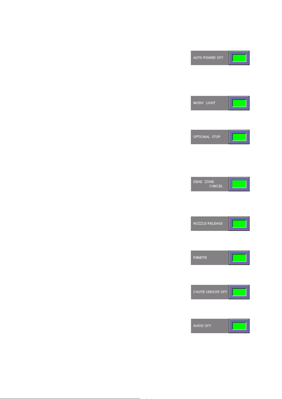
◯5 AUTO POWER OFF button
Press the AUTO POWER OFF
button. When the machine stops
after the end of its program operation
or after the occurrence of an alarm, it
can be automatically powered off.
◯6 WORK LIGHT button
Pressed to turn on the work light.
◯7 OPTIONAL STOP button
Pressed to pause the machine when
M01 (optional stop command) is
read.
Press the START button for the
machine to resume its operation.
◯8 DEAD ZONE CANCEL button
Pressed to disable the dead zone
detection function when the laser
head enters an area where it may
strike a workclamp.
◯9 NOZZLE RELEASE button
Pressed to release the nozzle for
nozzle change.
◯10 REMOTE button
Pressed to perform DNC operation
when the CNC operating mode is
selected.
◯11 CHUTE SENSOR OFF button
Pressed to disable the chute drop
detection function.
◯12 AVOID OFF button
Pressed to disable the workclamp
avoidance function when the
worksheet enters an area where it
may strike a workclamp.
I-15
Page 24
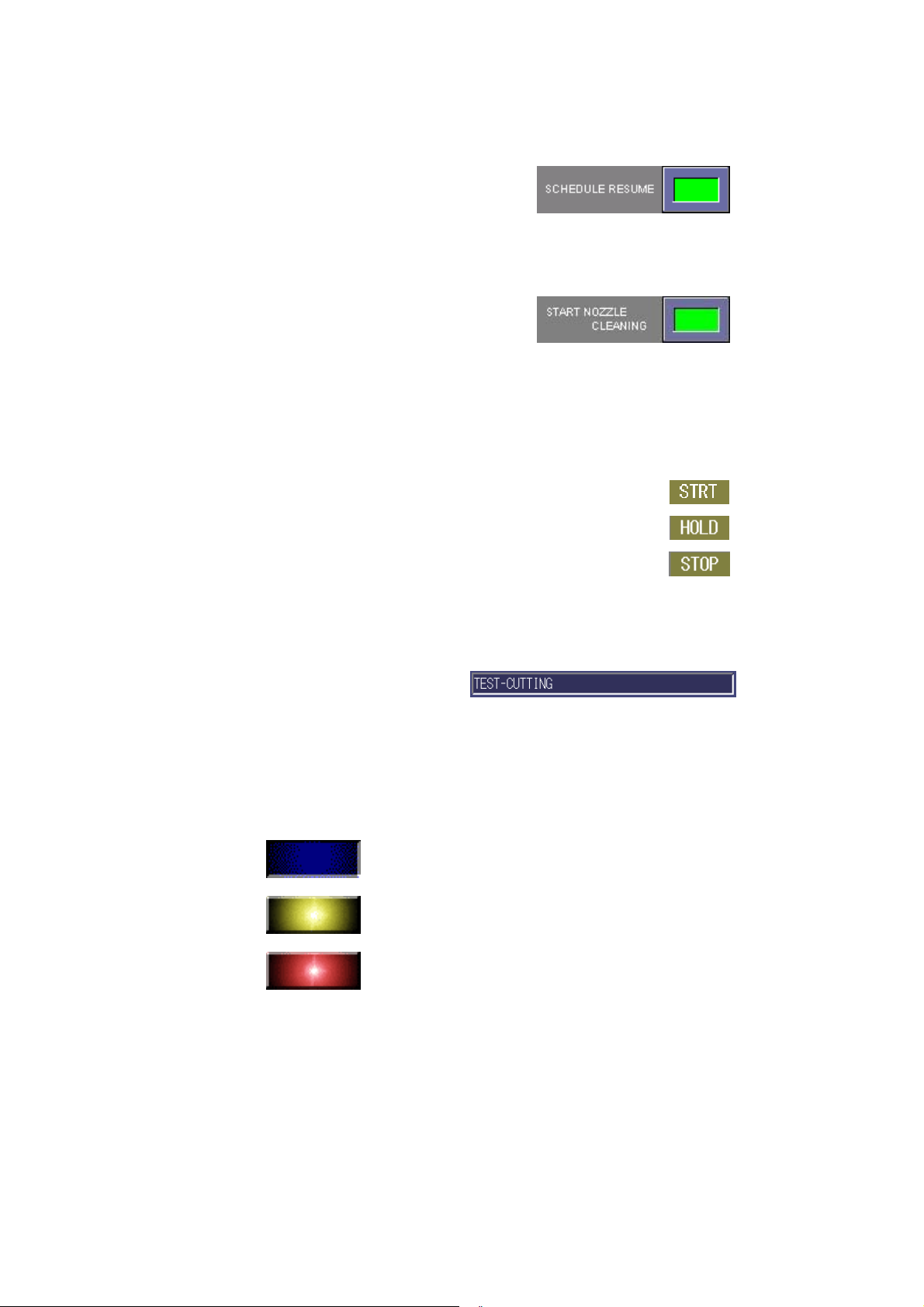
◯13 SCHEDULE RESUME button
Pressed to enable the machine to
resume its operation from where it is
stopped during its schedule
operation.
◯14 START NOZZLE CLEANING button
Pressed to enable the automatic
cleaning of the nozzle at the start of
the program.
[4] Processing status display field
Shows the processing status of the machine based on the NC status as
follows:
STRT: Shows the execution of a program.
HOLD: Shows the input of a stop signal.
STOP: Shows the input of a processing end signal.
[5] Running program display field
Shows the name of the
program being run or on
standby.
[6] Operating status display field
Shows the operating status of the machine.
Operation stopped (blue)
Warning occurred (flashing yellow)
I-16
Alarm occurred (steady red)
Page 25

[7] NC status display fields
◯1 ◯2 ◯3
1
◯
: Shows “Mcode” when an M-code is being run.
2
: Shows “EMG” when the machine is in an emergency stop condition.
◯
3
◯
: Displays the current NC mode.
REF: RETRACT mode MEM: MEMORY mode
JOG: MANUAL mode DNC: DNC mode
MDI: MDI mode EDIT: EDIT mode
I-17
Page 26
2-2. Processing status display area 2
(
)
Here are described the buttons and display items on the common area
of the SCHEDULE and PROGRAM displays.
COORDINATE
SYSTEM CHANGE
BUTTON
PROGRAM INDICATOR
GREEN
SCHEDULE INDICATOR (ORANGE)
Display items
Item Description
Coordinate system
change button
Cycle Time field Shows the processing time of the current
JOB end time field Shows the scheduled end time of the current
All process end time
field
Program indicator
(green)
JOB in operation
field
Schedule indicator
(orange)
Changes the current coordinate system
between the machine coordinate system and
absolute coordinate system.
program.
job.
Shows the scheduled end time of the current
schedule.
Shows the progress of the program relative to
the scheduled processing time. Appears
yellow when the program is stopped.
Shows the number of processed jobs relative to
the total number of jobs.
Shows the progress of the program relative to
the total number of worksheets scheduled.
I-18
Page 27

NOTE
O The all process end time (or scheduled end time of all processing operations)
is calculated from the time settings made on the User settings display as
described in 9-9. in this Part. This is also true of the job end time.
O If the program information does not include the scheduled processing time,
the progress of the program is not shown.
O The actual processing time may be different from the scheduled processing
time.
I-19
Page 28
2-3. Data edit area
Here are described the display items and buttons on the common areas
of the PRE-EDIT, SCHEDULE, and PROGRAM displays.
OPERATING MODE
CHANGE BUTTONS
Press SWITCH button
to change menu
PROGRAM display has
no SWITCH button
I-20
Page 29
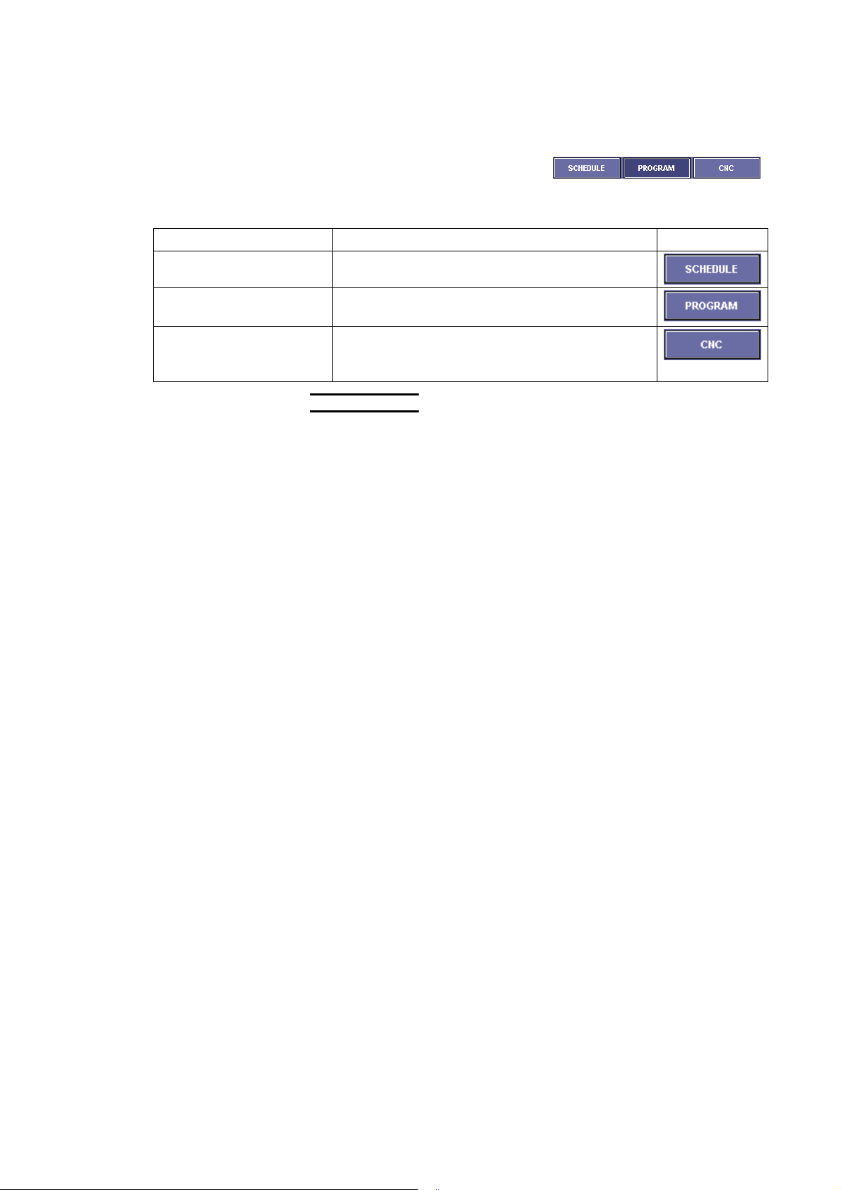
[1] Operating mode change buttons
Change the automatic operating
mode of the machine to suit a
particular operating procedure.
Item Description
SCHEDULE button Performs the schedule operation of the machine.
PROGRAM button Performs the single-program operation of the
machine.
CNC button Performs the CNC operation of the machine.
Press the REMOTE button on PANEL B to
perform the DNC operation.
NOTE
O The automatic operating mode of the machine cannot be changed while it is
operating.
O Change the automatic operating mode on the SCHEDULE or PROGRAM
display. It cannot be changed on the PRE-EDIT display.
I-21
Page 30
[2] List display items
The display items are as shown below.
Item Description Icon
C cell Deselects the data indicated by a green line.
Tool change and setup Not used on the laser cutting machine.
Material change and
setup
Workclamp position
change and setup
Laser setup Appears when it is necessary to change the
Prg Name Shows the program name.
Prcss Qty. Shows the number of worksheets to be
Actual # Shows the number of worksheets already
Def. Qty. Shows the number of defective worksheets. It
Op. Status Shows whether the job is not yet started, is being
Start Time Shows the job start time during the schedule
Finish Time Shows the job end time during the schedule
Actual Process Time Shows the time taken to process one worksheet
Material Name Shows the material name.
Schedule Name Shows the schedule name.
In Rack Sets the number of the shelf onto which to load
Out Rack Sets the number of the shelf from which to unload
Reserved Reserved for an optional unit like a loader or
Appears when it is necessary to change the
worksheet.
Appears when it is necessary to change the
workclamp position.
setup as the processing conditions change.
processed. It can be set on this display.
processed. It can be set on this display.
can be set on this display.
processed, or is normally completed. The job
skip function can also be selected.
operation.
operation.
during the schedule operation.
worksheets when an autostorage unit is installed.
parts when an autostorage unit is installed.
unloader.
I-22
*The display items depend on the search conditions.
Page 31

[3] OPEN button
Calls a program or schedule to the
data edit area.
1 Press the OPEN button to open the OPEN display.
2 Select the source
media, press the
SWITCH button to
SELECT MEDIA
SELECT WHETHER TO
CALL PROGRAM OR
SCHEDULE
show a list of
programs or
schedules, select the
program or schedule
you want to call from
the list, and press the
OK button.
Item Description
SDD button Lists the programs or schedules registered in
the SDD system.
FD button Lists the programs or schedules registered in
the floppy disk.
NC button Lists the programs or schedules saved in the
AMNC unit.
SHARED
HOLDER
Lists the programs or schedules saved in the
specified shared folder.
button
SWITCH button Changes the listed data between the programs
and schedules.
SEARCH
Searches the program or schedule list.
button
SCHEDULE
DETAILS
Shows the contents of each schedule. Select
the schedule, and press the button.
button
Enter key field Type the name of a program, and press the
ENTER key on the keyboard to search for the
program. When the name of the program is
read with a bar code reader, it is shown here.
“Quick search
is reflected on
Checked to reflect the typed search condition in
the program name on the search display.
condition” box
I-23
Page 32

NOTE
O The SDD system is Amada’s data management system composed of
the automatic programming unit AP100, AP60 or AP40 and the data
server ASIS100PCL.
O The specified shared holder is the holder that is set as shared holder on
the SPECIFY DRIVE display as described on 9-9. in this Part. If no
shared holder is specified, the SHARED HOLDER button is grayed out.
3 If there is a program
of the same name as
that of the selected
program, the Confirm
overwrite display
opens as shown right.
Item Description
SCHEDULE
REGIST button
Registers the called program with the same
contents as those of the registered program.
OK button Registers the called program by overwriting the
existing program of the same name with it.
CANCEL
Returns to the Open display.
button
4 Enter the number of
worksheets to be
processed, and press
the OK button to
register the program
on the Open display.
I-24
Item Description
OK button Registers the job with the entered number of
worksheets to be processed.
CANCEL
Returns to the Open display.
button
Page 33

NOTE
O Only one program can be called in the PROGRAM mode.
O The items shown on the Qty. input display vary with the “Enter Process
Qty screen” setting made on the SELECT VIEW display as described
on 9-9 in this Part.
O The display shown below opens when you press the PRE-EDIT or
SCHEDULE monitor CHANGE button and check the In rack and Out
rack fields on the SELECT VIEW display as described on 9-9 in this
Part.
Item Description
MULTI RACK
button
Specifies the number of worksheets for each
shelf, number of each shelf, etc.
I-25
Page 34

[4] SAVE button
Saves the selected program.
1 Select the program
you want to save, and
press the Save to
button to open the
Save data display.
Item Description
RENAME
button
DELETE button Removes the selected program from the
SDD button Saves the program in the SDD system.
NC button Saves the program in the NC unit. (Select the
NEW button Creates a new folder in the storage area of the
FD button Saves the program in the floppy disk.
SHARED
HOLDER
button
Overwrite
confirm box
NOTE
O Multiple programs can be selected for saving on the PRE-EDIT and
SCHEDULE displays.
2 Specify the
destination, and press
the OK button to open
the Confirm saved
data display.
Check the program
name and other
items, and press the
EXECUTE button.
Changes the name of the selected program.
programs to be saved.
(Select the folder to which to save the
program.)
folder in which to save the program.)
NC unit.
Saves the program in the specified shared
folder.
Asks whether or not to overwrite a program of
the same name with the new program when
saving the new program.
I-26
Page 35

Item Description
RENAME
button
DELETE button Removes the program from the programs to be
ABORT button Aborts the save.
BACK button Returns to the Save display.
EXECUTE
button
3 When the Saving data
display changes to
“Saved”, press the OK
button.
If the “Close
automatically when
process is complete”
box is checked, the
display shown right
will automatically
close from the next
time on.
Changes the name of the program.
saved.
Saves the selected data.
4 Press the EXIT button to close the window.
[5] COPY button
Copies the selected program.
Select the program you want to copy,
and press the button.
[6] PASTE button
Pastes the copied data on the data
edit area.
Select the destination list line, and
press the button.
[7] DELETE button
Deletes the selected program.
Select the program you want to
delete, and press this button.
I-27
Page 36

[8] DELETE ALL button
Deletes all programs registered on
the display.
[9] MOVE DOWN button
Moves down the program selected
on the display.
Select the program you want to
move down, and press the button.
[10] MOVE UP down
Moves up the program selected on
the data edit area.
Select the program you want to
move up, and press the button.
[11] SCHEDULE SAVE button
When a job is saved as schedule, it
can be simply called next time.
1 Select the job you want to save as schedule, and press the
SCHEDULE SAVE button.
2 Enter the name of the
schedule in the
Schedule name filed
on the Type Schedule
Name display, and
press the OK button.
3 Specify the
destination, and press
the OK button.
I-28
Page 37

4 Press the OK button.
5 Press the BACK
button to close the
display.
I-29
Page 38

[12] EDIT button
Changes the program placed on the
data edit area.
Select the program you want to
change, and press the button to
open the Edit display.
EDIT AREAS
SETUP AND G CODE BUTTONS
DRAW AREAS
* Shown above is the Edit display that opens when the G CODE button
is pressed
The buttons on the Edit display are described in detail below.
• SETUP display
Shows the setup
information of the selected
program.
Entry of accurate
information on the SETUP
display allows you to utilize
the setup function.
I-30
Page 39

• G CODE display
Shows the edit and draw areas.
Item Description
DRAWINGS button Draws the part in the draw area according to
the program shown in the edit area.
STEP DRAW button Draws the part in the draw area sequentially
according to the program lines selected in the
edit area.
Even when the down arrow key on the
keyboard is pressed, the part is sequentially
drawn.
When the STEP DRAW button is pressed, the
DRAWINGS button changes to the END DRAW
button. Press the END DRAW button to abort
the step draw.
When the draw process is completed, the END
DRAW button changes to the DRAWINGS
button.
G←DIAGRAM
button
FIRST LINE button Places the cursor at the first line of the program
LAST LINE button Places the cursor at the last line of the program
ENLARGE button Enlarges the selected portion of the figure
REDUCE button Reduces the selected portion of the figure
CENTER button Places the selected portion of the figure at the
AUTOSCALE button Shows the drawn figure to the size of the draw
STANDARD button Shows the position of the part in the worksheet
Highlights the G code for the selected portion of
the drawn figure.
Press the button, and select the portion of the
figure whose G code you want to check.
shown in the edit area.
shown in the edit area.
drawn in the draw area.
Press the button, and select the portion of the
figure you want to expand.
drawn in the draw area.
The reduction is referenced to the center of the
draw area.
center of the draw area.
area.
whose dimensions are set on the SETUP
display.
I-31
Page 40

Item Description Display
PARAM button Sets the drawing parameters.
Refresh during edit
Redraws a G code each time the cursor moves to the next or previous
line during the G code edit process.
Execute drawing on startup
Automatically draws the part in the draw area when the EDIT button is
pressed.
Display Scale
Shows the coordinates in the background of the draw area.
Display multiple process frame
Shows the multiple process frame in the draw area.
Scale
Sets the enlargement or reduction ratio when the ENLARGE or
REDUCE button is pressed, respectively.
Drawing color
Fixing:
Draws all paths in the default color (pink).
Cutting condition:
Draws the paths in different colors for different processing conditions.
E1: Blue, E2: Light blue, E3: Yellow, E4: White, E5 to E9: Red, E10
(marking line): Broken pink line, No condition: Pink
I-32
Page 41

Item Description Display
SEARCH button Opens the Search display.
Enter the character string to
find, select the search direction
(Up or Down), and press the
SEARCH NEXT button. To quit
the Search display, press the
BACK button.
REPLACE button Opens the Replace characters
display.
COPY button Opens the Specify the line that
you want to copy/cut display.
CUT: Cuts the specified range.
COPY: Copies the specified
range.
Item Description
PASTE button Pastes the data copied with the COPY button.
Select the destination line, and press the button
EXTRACT T button Not used on the laser cutting machine.
CHECK T button Not used on the laser cutting machine.
TOOLING button Not used on the laser cutting machine.
NEW button Creates a program.
MULT. PROC. button Opens the Multi display.
OK button Registers the edited data in the PRE-EDIT display.
BACK button Aborts the processing and returns to the PRE-EDIT display.
I-33
Page 42

[13] DRAWING button
Draws the part according to the data
of the program on the data edit area.
Select the program to use for
drawing the part, and press the
DRAWING button to open the
Confirm drawing display.
The buttons on the Confirm drawing display are described in detail
below.
Item Description
ENLARGE button Enlarges the figure drawn.
Press the button, and select the portion of the
figure you want to enlarge.
REDUCE button Reduces the figure shown enlarged.
Press the button to reduce the figure as
referenced to the center of the display.
CENTER button Changes the display position.
Press the button, and select the portion of the
figure you want to show as the center of the
display.
AUTOSCALE button Draws the figure on an automatic scale.
STANDARD button Shows the position of the part in the worksheet
whose dimensions are set on the SETUP
display.
PARAM button Sets the drawing parameters.
REFERENCE
O For details of the parameters, refer to “2-3. Data edit area, [12] EDIT button”
in this Part.
I-34
Page 43

[14] SIM button
Calculates the setup of all programs
shown on the data edit area, and
shows the setup results.
The SIM button is not enabled
unless the Laser setup and
Material/clamp setup boxes are
checked on the Application settings
display.
SETUP ICON
Material setup Shows that the material name
Workclamp position setup Shows that the workclamp position
Laser setup Shows that the setup items checked
Press the setup icon to
open the Setup Main
display for the setup.
changes with the processing
condition data.
changes with the setup made on the
Edit display.
on the display as described in “9-10.
Application settings” change.
I-35
Page 44

NOTE
O The setup status can be checked by the color of each button.
Red: Setup required, Yellow: Setup under way, Gray: No setup to make or
setup completed.
O When there is only one setup item, either setup display automatically opens.
• Laser setup display
Opens when the processing conditions of the program specified by
M102 change.
The current setup items are shown on the left side, and the new setup
items are shown in red on the right side.
When the setup in a lower row is completed, press the SETUP
COMPLETE button.
To complete all setups at a time, press the EXIT ALL button.
Shown in red
at setup
Current setup
I-36
Page 45

• Material/clamp setup display
Opens when the material or clamp setup icon is selected or the
MATERIAL/CLAMP button on the Setup Main display is pressed.
Make new material and workclamp setups.
The buttons on the Material/clamp setup display are described below.
SETUP COMPLETE
button
BACK button Returns to the Setup Main display.
[15] TRANS JOB button
Specifies the job you want to transfer
from the PRE-EDIT display to the
PROGRAM display.
Select the job, press the TRANS
JOB button, and press the
CONFIRM button. The job is
transferred to the PROGRAM
display.
Current setup
Item Description
Pressed when each setup is completed.
Shown in
red at setup
I-37
Page 46

[16] START JOB button
Specifies the job on the SCHEDULE
display from which you want to start
the schedule operation.
Select the job from which you want
to start the schedule operation, and
press the START JOB button. The
selected job is indicated by a yellow
arrow.
The schedule operation is started at
the specified job.
[17] PRG. INFO button
Shows the setup and other
information of the selected program.
I-38
Page 47

[18] RETRY button
Retry is a function of resuming the
operation by feeding or returning
from the middle or start position of
the program on a part basis (pierce
point) and on a block basis (single
block).
O Before using the retry function, the Z-axis must be raised to prevent it from
O The following functions and commands do not properly operate:
◯1 HS edge detection function (G121, G122)
◯
◯
◯
O Before using the retry function from the beginning of the program after reset,
NOTICE
striking an obstacle during its travel.
NOTE
2
OVS function (G140, G141, G149)
3
Measuring probe function (G120)
4
Repositioning function (G25, G27)
be sure to return each axis to the start position. Otherwise the axes do not
properly operate.
1
◯
2
◯
3
◯
4
◯
◯1 NEXT PART button
Press the NEXT PART button, turn
the SHUTTER OPEN keyswitch to
OFF, and press the START button to
move the axis to the start position
(pierce position) of the next path.
A multiple-part processing program moves the axis to the next part
reference point.
I-39
Page 48

◯2 PREV. PART button
Press the PREV. PART button, turn
the SHUTTER OPEN keyswitch to
OFF, and press the START button to
move the axis to the start position
(pierce position) of the previous path.
A multiple-part processing program moves the axis to the previous part
reference point.
◯3 NEXT BLOCK button
Press the NEXT BLOCK button, turn
the SHUTTER OPEN keyswitch to
OFF, and press the START button to
rapid the axis to the next block.
◯4 PREV. BLOCK button
Press the PREV. BLOCK button, turn
the SHUTTER OPEN keyswitch to
OFF, and press the START button to
rapid the axis to the previous block.
◯5 CLOSE button
Ends the retry function and closes
the Retry display.
After closing the Retry display, press the START button to cause the
machine to start processing from that position.
I-40
Page 49

[19] RESUME button
The resume function allows the axis
to rapid to the stopped position after
it is stopped by pressing the STOP
button, for example.
O Never perform the following operations until performing the resume function.
Otherwise the machine does not properly operate:
1
◯
2
◯
3
◯
4
◯
O The following functions and commands do not properly operate:
◯1 HS edge detection function (G121, G122)
2
◯
3
◯
4
◯
NOTE
Calling and using another program to operate the machine
Editing the resume program
Changing the processing conditions
Turning the TRACE OFF button to ON or OFF
OVS function (G140, G141, G149)
Measuring probe function (G120)
Repositioning function (G25, G27)
• RESUME button
Press the RESUME button, and then
press the START button to rapid the
axis to the position where it was
stopped last time.
• CLOSE button
Ends the retry function and closes
the Resume display.
After closing the Resume display, press the START button to cause the
machine to start processing from that position.
NOTE
O Depending on the resume position, the machine may be unable to resume its
operation properly due to a processing defect, for example. In such a case,
use the retry function to adjust the processing resume position.
I-41
Page 50

[20] MULT. PROC. button
The multiple-part processing function
allows the multiple-part processing
settings to be corrected simply by
changing the display settings of a
single-part or multiple-part
processing program.
REFERENCE
O For details of the multiple-part processing function, refer to “8-4. Setting
multiple-part processing” in Part II, Program management.
I-42
Page 51

2-4. Status icons
The current status is indicated by an icon at the lower right of the
screen. The meanings of the icons are as described in the table
below.
ICON
No. Icon Meaning Description
1
2
3
4
5
6
7
8
Event being
monitored
Dial-up connection
being made
Event being
monitored and
dial-up connection
being made
Mail transmission
failed and event
monitoring stopped
Inspection date
overdue
Backup date overdue The icon means that there is data past the backup
Automatic backup
failed
Recovery item set The icon means that a recovery item is set. The item
An event is being monitored. The icon means that
event monitoring is normally started.
The icon means that the dial-up connection specified
on the Setup of E-mail Notice display is being made.
The icon means that the machine is in both of the
status 1 and 2.
While an event was being monitored, another event
occurred, and mail transmission was attempted but
failed. The failure of mail transmission automatically
stops the event monitoring process.
The icon does not appear when the transmission of
mail from the E-mail Transmission display failed.
Check the message to see if the mail transmission
succeeded or failed.
If the icon is not shown during the event monitoring
process, the items may not be properly set on the
Setup of E-mail Notice display, or the network may not
be properly functioning. Remove the cause of the
problem.
The icon means that there is an overdue inspection
item. Inspect the overdue item.
date.
The icon means that automatic backup failed.
is recovered at the next startup.
I-43
Page 52

3. PRE-EDIT DISPLAY (BACKGROUND)
Press the PRE-EDIT button to open
the PRE-EDIT display to create or
edit the next program while the
machine is operating.
You can also check the setup of the
next program and check the next
part by drawing it while the machine
is operating.
OPERATING MODE
3-1. Creating program from PRE-EDIT
display
REFERENCE
O For details of the display, refer to “1-1. Creating program from PRE-EDIT or
SCHEDULE display” in Part II, Program management.
1 With no job selected, press the EDIT button.
2 Enter the program name, and press the G CODE button.
3 Enter the G code program in the left edit area.
I-44
Page 53

4 After creating the program, press the DRAWINGS button to draw
the part according to the program in the right draw area, and
check the program.
NOTE
O If the drawn figure overfills the draw area, press the AUTOSCALE
button.
5 After checking the program, press the OK button.
3-2. Calling program from PRE-EDIT display
REFERENCE
O For details of the display, refer to “2-1. Calling program from PRE-EDIT or
SCHEDULE display” in Part II, Program management.
1 Press the OPEN button to open the OPEN display.
2 Press the source media, and press the SWITCH button to select
whether to call a program from the program data list or schedule
data list. Select the necessary data from the list, and press the
OK button.
Two or more programs can be called at a time.
If the program you want to call cannot be found although you have
saved it, it may be saved in another folder. Press the SEARCH
button to open the Search display. Enter the folder name in the
Folder name field, and search for the folder.
REFERENCE
O For the searching procedure, refer to “9. Searching for program” in Part
II, Program management.
NOTE
O If the selected
program is present as
job, the Confirm
overwrite display
opens as shown right.
I-45
Page 54

SCHEDULE
REGIST button
Registers the called program without
overwriting a program of the same name with
it.
OK button Registers the called program by overwriting a
program of the same name with it.
O If the selected
program is registered
on the PROGRAM
display, the Confirm
overwrite display
opens as shown right.
3 Enter the number of worksheets to be processed, and press the
OK button. If you have called multiple programs, check their
names, and enter the number of worksheets to be processed for
each program.
NOTE
O The In rack, Out rack, and Reserve fields are for an autostorage unit.
If the machine is not equipped with an autostorage unit, it is not
necessary to enter any values in these fields.
O The MULTI RACK button is provided for using another autostorage. If
the machine is not equipped with another autostorage unit, the MULTI
RACK button is not necessary.
O The items shown on the Qty. input display vary with the settings made
on the Schedule monitor list item display opened by pressing the
CHANGE button on the Schedule monitor display as described on 9-9
in this Part.
4 The selected program is registered on the PRE-EDIT display.
I-46
Page 55

3-3. Saving program from PRE-EDIT display
REFERENCE
O For details of the display, refer to “3-1. Saving program from PRE-EDIT or
SCHEDULE display” in Part II, Program management.
1 Select the program you want to save, and press the SAVE button.
(You can select and save multiple programs at a time.)
2 Specify the destination, and press the OK button.
NOTE
O If the Confirm overwrite box is checked, the program to be overwritten
is shown in red characters on the next Confirm overwrite display.
3 Check the program to save, and press the EXECUTE button.
4 When the Saving data display changes to “Saved”, press the OK
button.
NOTE
O If the “Close automatically when process is complete” box is checked,
the display shown right will automatically close from the next time on.
5 After checking that the program is saved, press the OK button.
3-4. Transferring job to PROGRAM display
Select the job you want to transfer to the PROGRAM display.
Check that the automatic operating mode is PROGRAM, select the job
to be transferred to the PROGRAM display, and press the TRANS JOB
button.
NOTE
O If the automatic operating mode is PROGRAM, only one program can be
called.
O Change the automatic operating mode on the SCHEDULE or PROGRAM
display. It cannot be changed on the PRE-EDIT display.
I-47
Page 56

3-5. Transferring selected job
Press the TRANS JOB button to transfer the selected job to the
PROGRAM display.
NOTE
O If the CONFIRM button is pressed here, the data shown on the PROGRAM
display is deleted.
3-6. Transferring schedule to SCHEDULE
display
Transfer the schedule (all jobs) from the PRE-EDIT display to the
SCHEDULE display.
Check that the automatic operating mode is SCHEDULE.
To transfer a new schedule to the SCHEDULE display, press the
CONFIRM button.
To add another schedule to the schedule already transferred to the
SCHEDULE display, press the ADD button.
NOTE
O Change the automatic operating mode on the SCHEDULE or PROGRAM
display. It cannot be changed on the PRE-EDIT display.
O If the CONFIRM button is pressed here, the data shown on the SCHEDULE
display is deleted.
I-48
Page 57

4. SCHEDULE DISPLAY
Press the SCHEDULE button to
open the SCHEDULE display to read
a schedule, create a schedule, and
set the start and end jobs. You can
also check the setup of the machine
and check the part by drawing it
before operating the machine.
Operating mode change buttons
Change the automatic operating mode of the machine.
To perform the schedule operation of the machine, press the
SCHEDULE button.
Item Description
SCHEDULE button Performs the schedule operation of the
machine.
PROGRAM button Performs the single-program operation of the
machine.
CNC button Performs the CNC operation of the machine.
NOTE
O The automatic operating mode of the machine cannot be changed while it is
operating.
I-49
Page 58

4-1. Creating program from SCHEDULE
display
1 With no job selected, press the EDIT button.
REFERENCE
O For details of the display, refer to “1-1. Creating program from
PRE-EDIT or SCHEDULE display” in Part II, Program management.
2 Enter the program name, and press the G CODE button.
3 Enter the G code program in the left edit area.
4 After creating the program, press the DRAWINGS button to draw
the part according to the program in the right draw area, and
check the program.
NOTE
O If the drawn figure overfills the draw area, press the AUTOSCALE
button.
5 After checking the program, press the OK button.
4-2. Calling program from SCHEDULE
display
1 Press the OPEN button to open the OPEN display.
REFERENCE
O For details of the display, refer to “2-1. Calling program from PRE-EDIT
or SCHEDULE display” in Part II, Program management.
2 Press the source media, and press the SWITCH button to select
whether to call a program from the program data list or schedule
data list. Select the necessary data from the list, and press the
OK button.
Two or more programs can be called at a time.
If the program you want to call cannot be found although you have
saved it, it may be saved in another folder. Press the SEARCH
button to open the Search display. Enter the folder name in the
Folder name field, and search for the folder.
I-50
Page 59

NOTE
O If the selected
program is present as
job, the message
display appears as
shown right.
SCHEDULE
REGIST button
Registers the called program without
overwriting a program of the same name with
it.
OK button Registers the called program by overwriting a
program of the same name with it.
O If the selected
program is registered
on the PROGRAM
display, the message
display appears as
shown right.
3 Enter the number of worksheets to be processed, and press the
OK button. If you have called multiple programs, check their
names, and enter the number of worksheets to be processed for
each program.
NOTE
O The In rack, Out rack, and Reserve fields are for an autostorage unit.
If the machine is not equipped with an autostorage unit, it is not
necessary to enter any values in these fields.
O The MULTI RACK button is provided for using another autostorage. If
the machine is not equipped with another autostorage unit, the MULTI
RACK button is not necessary.
O The items shown on the Qty. input display vary with the settings made
on the Line setting display as described in this Part.
4 The selected program is registered on the SCHEDULE display.
I-51
Page 60

4-3. Saving program from SCHEDULE
display
1 Select the program you want to save, and press the SAVE button.
(You can select and save multiple programs at a time.)
REFERENCE
O For details of the display, refer to “3-1. Saving program from PRE-EDIT
or SCHEDULE display” in Part II, Program management.
2 Specify the destination, and press the OK button.
NOTE
O If the Confirm overwrite box is checked, the program to be overwritten
is shown in red characters on the next Confirm saved data display.
3 Check the program to save, and press the EXECUTE button.
4 When the Saving data display changes to “Saved”, press the OK
button.
NOTE
O If the “Close automatically when process is complete” box is checked,
the display shown right will automatically close from the next time on.
5 After checking that the program is saved, press the OK button.
4-4. Selecting start job
Specify the first job at which to perform the schedule operation of the
machine.
Select the start job, and press the START JOB button. The selected
job is indicated by a yellow arrow.
The schedule operation is started at the specified job and performed to
the last job.
I-52
Page 61

5. PROGRAM DISPLAY
Press the PROGRAM button to open
the PROGRAM display to show a
processing program. You can also
check the setup of the machine and
check the part by drawing it before
operating the machine.
OPERATING MODE
CHANGE
Operating mode change buttons
Change the automatic operating mode of the machine.
To perform the program operation of the machine, press the
PROGRAM button.
Item Description
SCHEDULE button Performs the schedule operation of the
machine.
PROGRAM button Performs the single-program operation of the
machine.
CNC button Performs the CNC operation of the machine.
NOTE
O The automatic operating mode of the machine cannot be changed while it is
operating.
I-53
Page 62

5-1. Creating program from PROGRAM
display
1 Change the automatic operating mode to PROGRAM, and press
the EDIT button.
REFERENCE
O For details of the display, refer to “1-2. Creating program from
PROGRAM display” in Part II, Program management.
2 Press the NEW button.
3 Enter the program name, and press the G CODE button.
4 Enter the G code program in the left edit area.
5 After creating the program, press the DRAWINGS button to draw
the part according to the program in the right draw area, and
check the program.
NOTE
O If the drawn figure overfills the draw area, press the AUTOSCALE
button.
6 After checking the program, press the OK button to end the edit.
5-2. Calling program from PROGRAM display
1 Press the OPEN button to open the OPEN display.
REFERENCE
O For details of the display, refer to “2-2. Calling program from
PROGRAM display” in Part II, Program management.
2 Select the media that contains the program you want to call, select
the program from the data list, and press the OK button.
NOTE
O If the program you want to call cannot be found, it may be saved in
another folder. Press the SEARCH button to open the Search display.
Enter the folder name in the Folder name field, and search for the
folder.
I-54
Page 63

NOTE
O If the selected
program is present on
the PRE-EDIT,
SCHEDULE, or
PROGRAM display,
the Confirm overwrite
display opens as
shown right.
YES button Registers the called program without
overwriting a program of the same name with
it.
NO button Registers the called program by overwriting a
program of the same name with it.
3 The selected program is shown on the PROGRAM display.
NOTE
O If a setup display is shown, set up the item shown in red characters,
and press the SETUP COMPLETE button. Then press the BACK
button to close the setup display.
5-3. Saving program from PROGRAM display
1 Change the automatic operating mode to PROGRAM, and press
the SAVE button.
REFERENCE
O For details of the display, refer to “3-2. Saving program from
PROGRAM display” in Part II, Program management.
2 Specify the destination, and press the OK button.
NOTE
O If the Confirm overwrite box is checked, the program to be overwritten
is shown in red characters on the next Confirm saved data display.
3 Check the program to save, and press the EXECUTE button.
4 When the Saving data display changes to “Saved”, press the OK
button.
NOTE
O If the “Close automatically when process is complete” box is checked,
the display will automatically close from the next time on.
5 After checking that the program is saved, press the OK button.
I-55
Page 64

6. RESULT DISPLAY
Press the RESULT display to open
the RESULT display to show a
history of programs run to operate
the machine.
HISTORY DISPLAY
I-56
History display change buttons
Change the unit in which the
program history is shown.
Item Description Icon
Program Unit Shows the program history when
one job is completed during the
schedule operation.
One Unit Shows the program history when
one program is completed.
Page 65

Statistical Info fields
Show the statistical information of the entire processing history.
Item Description
Total Process Time Shows the total processing time with the
programs registered on the RESULT display.
Avr Process Time Shows the average processing time with the
programs registered on the RESULT display.
Created Data Shows the total number of worksheets
processed with the programs registered on the
RESULT display. The number of defective
parts are not included.
Program count Shows the number of listed programs with
respect to the total number of programs.
Display items
The display items are as described below.
Item Description
C Deselects the data indicated by a green line.
Result Register Date Shows the date when a program was registered
on the RESULT display.
Program Name Shows the program name. It cannot be set
here.
Start Date & Time Shows the date and time when processing with
the program was started.
End Date & Time Shows the date and time when processing with
the program was ended.
Qty Shows the number of worksheets processed.
Press each item to rearrange the data in ascending or descending
order. What is to be displayed depends on the search condition.
I-57
Page 66

[1] SEARCH button
Opens the Search display.
Specify the program name and result
registration date you want to search
for, and press the OK button.
Program Name Enter the program name.
Input range Alphabetic characters (capital), numerals, -, +, *
Item Description
Wild cards (*, A*, *A, *A*) can be specified.
[2] FILE OUTPUT button
Outputs all of the listed data to a file.
Enter the output folder name and file
name, and press the OK button.
I-58
Page 67

O Press the REFERENCE button on the File Output (Process History) display
[3] DELETE button
Deletes the selected data from the
processing history information.
NOTE
to select the destination as shown below.
[4] DELETE ALL button
Deletes all of the listed data from the
processing history information.
[5] UPDATE button
Updates the listed data with the
current processing history.
Each time a part is processed, the
processing history is updated, and
the UPDATE button is illuminated.
Unless the UPDATE button is
pressed at that time, the processing
data is not shown on the RESULT
display.
REFERENCE
O For the timing of update, refer to “Registering processing results” on 9-9 in
this Part.
I-59
Page 68

7. UTILITY DISPLAY
Press the UTILITY button to open
the UTILITY display to zero-return
the machine and make various
adjustments.
I-60
NOTE
O The utility operations can be performed only when the NC mode is MEMORY.
When you attempt to open a utility display in any other mode (RETRACT,
MANUAL, MDI, or EDIT), the following message display opens.
Change the NC mode to MEMORY, and press the RETRY button or press
the CANCEL button to cancel the utility operation. The message display
closes.
Page 69

7-1. G50
Press the G50 button to Open the G50 display.
COORDINATE DISPLAY
AREA
Display items
Item Description
CLOSE button Closes the G50 display.
Coordinate system
change button
Coordinate display
area
Changes the current coordinate system
between the machine coordinate system and
absolute coordinate system.
Show the absolute or machine coordinate
position.
Operating
1 Check that the NC mode is MEMORY.
2 Press the G50 button to open the G50 display.
3 Press the START button to zero-return each axis of the machine.
The G90 display closes when the zero-return motion is completed.
I-61
Page 70

7-2. Return to 2nd Machine Position
Press the Return to 2nd Machine Position button to open the Return to
2nd Machine Position display.
COORDINATE DISPLAY
AREA
Display items
Item Description
CAPTURE button Sets the current positions of the X-, Y-, and
Z-axes as the position of the origin.
DEFAULT button Defaults the origin positions X, Y, and Z.
Coordinate system
change button
CLOSE button Closes the Return to 2nd Machine Position
2nd Machine
Position X field
2nd Machine
Position Y field
2nd Machine
Position Z field
Coordinate display
area
Changes the current coordinate system
between the machine coordinate system and
absolute coordinate system.
display.
Sets the X-axis position of the origin.
(Setting range: -9999.99 to +99999.99 mm)
Sets the Y-axis position of the origin.
(Setting range: -99999.99 to +99999.99 mm)
Sets the Z-axis position of the origin.
(Setting range: -99999.99 to +99999.99 mm)
Show the absolute or machine coordinate
position.
I-62
Page 71

7-3. G00
Operating
1 Check that the NC mode is MEMORY.
2 Press the Return to 2nd Machine Position button to open the
Return to 2nd Machine Position display.
3 Press the START button to rapid each axis of the machine to the
positions set in the 2nd Machine Position X, Y, and Z fields.
The Return to 2nd Machine Position display closes when the rapid
motion is completed.
Press the G00 button to Open the G00 display.
COORDINATE DISPLAY
AREA
Display items
Item Description
Coordinate system
change button
ABSOLUTE POS.
button
RELATIVE POS.
button
CLOSE button Closes the G00 display.
Absolute Position X
field
Absolute Position Y
field
Coordinate display
area
Changes the current coordinate system
between the machine coordinate system and
absolute coordinate system.
Moves the laser head to the preset absolute X
or Y coordinate position.
Moves the laser head along the X- or Y-axis by
the preset distance.
Sets the absolute position of X-axis.
(Setting range: -99999.99 to +99999.99 mm)
Sets the absolute position of Y-axis.
(Setting range: -99999.99 to +99999.99 mm)
Show the absolute or machine coordinate
position.
I-63
Page 72

Operating
1 Check that the NC mode is MEMORY.
2 Press the G00 button to open the G00 display.
3 Press the START button to rapid each axis of the machine to the
positions set in the Absolute Position X and Y fields.
The G00 display automatically closes when the rapid motion is
completed.
7-4. Nozzle/Head Exchange Position
Press the Nozzle/Head Exchange Position button to Open the
Nozzle/Head Exchange Position display.
COORDINATE DISPLAY
AREA
Display items
Item Description
CAPTURE button Sets the current positions of the X-, Y-, and
Z-axes.
DEFAULT button Defaults the change positions X, Y, and Z.
Coordinate system
change button
CLOSE button Closes the Nozzle/Head Exchange Position
Exchange Position X
field
Exchange Position Y
field
Changes the current coordinate system
between the machine coordinate system and
absolute coordinate system.
display.
Sets the X-axis change position.
(Setting range: -9999.99 to +99999.99 mm)
Sets the Y-axis change position.
(Setting range: -99999.99 to +99999.99 mm)
I-64
Page 73

Item Description
Exchange Position Z
field
Coordinate display
area
Sets the Z-axis change position.
(Setting range: -99999.99 to +99999.99 mm)
Show the absolute or machine coordinate
position.
Operating
1 Check that the NC mode is MEMORY.
2 Press the Nozzle/Head Exchange Position button to open the
Nozzle/Head Exchange Position display.
3 Press the START button to rapid each axis of the machine to the
positions set in the Exchange Position X, Y, and Z fields.
The Nozzle/Head Exchange Position display automatically closes
when the rapid motion is completed.
I-65
Page 74

7-5. JOG Cutting
Press the JOG Cutting button to open the JOG Cutting display.
This display prepares for jog cutting.
Display items
COORDINATE DISPLAY
AREA
Item Description
HEAD DOWN button Moves the head down toward the worksheet.
PIERCE button Moves down the head to pierce the worksheet.
The pierce condition to be used is the condition
used last time. (Refer to the name of the
processing condition shown.)
Coordinate system
change button
CLOSE button Closes the JOG Cutting display.
Processing condition
name field
Coordinate display
area
Changes the current coordinate system
between the machine coordinate system and
absolute coordinate system.
Shows the name of the processing condition
being used.
Show the absolute or machine coordinate
position.
Operating
1 Call the processing condition from the processing condition
display to suit the worksheet to be processed.
2 Moves the head in the MANUAL mode to the cutting start position.
3 Change the NC mode to MEMORY.
I-66
4 Press the JOG Cutting button to open the JOG cutting display.
5 Press the HEAD DOWN button, and press the START button to
move down the head.
Page 75

6 Press the PIERCE button, turn the SHUTTER OPEN keyswitch to
ON, and press the START button to pierce the worksheet.
Perform the jog cutting operation as described below.
1 When the above-mentioned operating procedure is completed,
change the NC mode to MANUAL.
2 Turn the MANUAL CUT keyswitch on the NC control panel to ON.
The “2598 jog cutting mode” warning occurs, but continue with the
procedure.
3 Press the MANUAL CUT ENABLE button on the shuttle table
control panel.
4 Press the axis feed button for the processing condition to start the
cutting operation in the direction of the axis feed button.
I-67
Page 76

7-6. Shuttle Exchange
Press the Shuttle Exchange button to open the Shuttle Exchange
display.
Display items
COORDINATE DISPLAY
AREA
Item Description
CLOSE button Closes the Shuttle Exchange display.
Coordinate system
change button
Coordinate display
area
Changes the current coordinate system
between the machine coordinate system and
absolute coordinate system.
Show the absolute or machine coordinate
position.
Operating
1 Check that the Z-axis is positioned at the origin and that the
WORK SET READY button on the control panel of the shuttle
table is illuminated.
2 Check that the NC mode is MEMORY.
3 Press the Shuttle Exchange button to open the Shuttle Exchange
display.
4 Press the START button to change the shuttle table. When the
change operation is completed, the Shuttle Exchange display
automatically closes.
I-68
Page 77

7-7. Adjust HS Sensor
Press the Adjust HS Sensor button to open the Adjust HS Sensor
display.
Display items
COORDINATE DISPLAY
AREA
Item Description
Adjustment Position
X field
Adjustment Position
Y field
MOVE button Rapids each axis to the positions set in the
ADJUSTMENT
button
CAPTURE button Sets the current positions of the X- and Y-axes.
DEFAULT button Defaults the adjustment positions of the X- and
Coordinate system
change button
CLOSE button Closes the Adjust HS Sensor display.
Coordinate display
area
Sets the adjustment position of the X-axis.
(Setting range: -99999.999 to +99999.99 mm)
Sets the adjustment position of the Y-axis.
(Setting range: -99999.999 to +99999.99 mm)
Adjustment Position X and Y fields.
Runs the HS sensor adjusting program.
Y-a xes .
Changes the current coordinate system
between the machine coordinate system and
absolute coordinate system.
Show the absolute or machine coordinate
position.
I-69
Page 78

Operating
1 Check that the NC mode is MEMORY.
2 Press the Adjust HS Sensor button to open the Adjust HS Sensor
display.
3 Press the axis feed buttons or MOVE button to move the head to
the calibration position. Check that the head is positioned above
the worksheet.
4 Press the ADJUSTMENT button, and press the START button to
start the calibration of the HS sensor.
7-8. Check Assist Gas
Press the Check Assist Gas button to open the Check Assist Gas
display.
COORDINATE DISPLAY
AREA
I-70
Page 79

Display items
Item Description
Gas Kind field Sets the type of assist gas to be adjusted.
(Setting range: 1 to 7)
Gas Pressure [MPa]
field
Time field Sets the adjustment time (assist gas ejection
DEFAULT button Defaults the setting values.
Coordinate system
change button
CLOSE button Closes the Check Assist Gas display.
Coordinate display
area
Sets the pressure of assist gas to be adjusted.
(Setting range: 0.00 to 2.55 MPa)
time).
(Setting range: 0.0 to 9999.9 sec)
Changes the current coordinate system
between the machine coordinate system and
absolute coordinate system.
Show the absolute or machine coordinate
position.
Operating
1 Check that the NC mode is MEMORY.
2 Press the Check Assist Gas button to open the Check Assist Gas
display.
3 Set the Gas Kind, Gas Pressure, and Time fields.
4 Press the START button to turn on the assist gas.
I-71
Page 80

7-9. Adjust the Nozzle Unit Centering
Press the Adjust the Nozzle Unit Centering button to open the Adjust
the Nozzle Unit Centering display.
COORDINATE DISPLAY
AREA
Display items
Item Description
Adjustment Position
X field
Adjustment Position
Y field
Adjustment Position
Z field
Power field Sets the power command value to be used.
Frequency field Sets the pulse frequency command value to be
Duty field Sets the pulse duty command value to be used.
Gas Kind field Sets the type of assist gas to be used.
Gas Pressure [MPa]
field
Time field Sets the centering time.
Sets the adjustment position of the X-axis.
(Setting range: –99999.999 to +99999.999 mm)
Sets the adjustment position of the Y-axis.
(Setting range: –99999.999 to +99999.999 mm)
Sets the adjustment position of the Z-axis.
(Setting range: –99999.999 to +99999.999 mm)
(Setting range: 0 to 7000 W)
used.
(Setting range: 5 to 2000 Hz)
(Setting range: 0 to 100%)
(Setting range: 1 to 7)
Sets the pressure of assist gas to be used.
(Setting range: 0.00 to 2.55 MPa)
(Setting range: 0.0 to 9999.9 sec)
I-72
Page 81

Item Description
Lens No. field Sets the lens to be used.
(Setting range: Auto, 5”, 7.5”, 10”, 3.75”, N/A).
The focal point position of the selected lens is
used for laser cutting. When AUTO is
selected, the focal point reference position
called as one of the processing conditions in
the processing condition file is used for laser
cutting.
Fine Adjust Focus
field
Sets the fine adjustment amount of the focal
point position. This field is usually set to 1.5
mm.
(Setting range: 0.0 to 99999.999)
MOVE button Rapids the X-, Y-, and Z-axes to the positions
set in the Adjustment Position X, Y, and Z fields.
ADJUSTMENT
Runs the centering program.
button
DEFAULT button Defaults the setting values.
Coordinate system
change button
Changes the current coordinate system
between the machine coordinate system and
absolute coordinate system.
CLOSE button Closes the Adjust the Nozzle Unit Centering
display.
Coordinate display
area
Show the absolute or machine coordinate
position.
NOTE
O When the TIME field is set to 0.6 sec or more, a confirmation display opens.
Press the OK button to complete the entry and show the time in red
characters. The laser beam is actually turned on for the time setting. Pay
full attention to the setting value of the TIME field.
Operating
1 Check that the NC mode is MEMORY.
2 Press the Adjust the Nozzle Unit Centering button to open the
Adjust the Nozzle Unit Centering display.
3 Press the axis feed buttons or MOVE button to move the head to
the position where it is easy to adjust the center of the nozzle unit.
Check that the there are no skid and worksheet below the head.
4 Press the ADJUSTMENT button, and press the START button to
adjust the center of the nozzle unit.
I-73
Page 82

7-10. Adjust Focus
Press the Adjust Focus button to open the Adjust Focus display.
Display items
Item Description
Material Name field Shows the name of the material to be used.
Lens No. field Sets the lens to be adjusted.
Condition No. field Sets the cutting condition to be used.
Start Focus Position
field
End Focus Position
field
Focus Change
Amount field
5” field Sets the focal point reference position when a
7.5” field Sets the focal point reference position when a
10” field Sets the focal point reference position when a
COORDINATE DISPLAY
AREA
(Setting range: 5, 7.5, 10, 3.75, N/A)
(Setting range: 1 to 10)
Sets the focal point position at which to start the
adjustment.
(Setting range:–99999.999 to +99999.999 mm)
Sets the focal point position at which to end the
adjustment.
(Setting range: –99999.999 to +99999.999 mm)
Sets the amount by which to adjust the focal
point.
(Setting range:–99999.999 to +99999.999 mm)
5” lens is used*.
(Setting range:–99999.999 to +99999.999 mm)
7.5” lens is used*.
(Setting range:–99999.999 to +99999.999 mm)
10” lens is used*.
(Setting range:–99999.999 to +99999.999 mm)
I-74
Page 83

Item Description
3.75” field Sets the focal point reference position when a
3.75” lens is used*.
(Setting range:–99999.999 to +99999.999 mm)
N/A field Sets the focal point reference position when no
lens is set for use*.
(Setting range:–99999.999 to +99999.999 mm)
*The selection of a lens limits the entry of a value for the lens.
Item Description
DEFAULT button Defaults the setting values.
Coordinate system
change button
CLOSE button Closes the Adjust Focus display.
AIV NOT USED
button
Coordinate display
area
Changes the current coordinate system
between the machine coordinate system and
absolute coordinate system.
Selects the nonuse of the AIV (OVS) system.
Show the absolute or machine coordinate
position.
Operating
1 Check that the NC mode is MEMORY.
2 Press the Adjust Focus button to open the Adjust Focus display.
3 Press the axis feed buttons to move the head to the position
where it cuts the worksheet.
4 Check the Material Name field. If the material is different from
that used for adjusting the focus, do as described in “Changing
material name” on the next page.
5 From the Lens No. pull-down menu, select the lens to be set at the
focal point reference position.
6 Set the Condition No., Start Focus Position, End Focus Position,
and Focus Change Amount fields. Or press the DEFAULT
button.
7 Turn the SHUTTER OPEN keyswitch to ON.
8 Press the START button. The head cuts 60-mm long slits at a
pitch of 8 mm by changing the focus position from the position set
in the Start Focus Position field to the position set in the End
Focus Position field at the interval set in the Focus Change
Amount field.
9 Find the smallest slit width. The focus position where the
narrowest slit can be cut is the optimum focus position.
10 In the Focus Point Reference Position field, enter the focus height
at which the narrowest slit is cut.
I-75
Page 84

Changing material name
1 With the Adjust Focus
display opened, press
the LIST button on the
COND. display to
open the List display.
2 Select the processing
condition file you want
to call, and press the
CALL button.
3 Check that the
selected processing
condition file is called,
and press the
REGISTER MTRL
button on the Adjust
Focus display.
4 The REGISTER
MTRL display opens.
If the processing
conditions are correct,
press the YES button.
I-76
Page 85

5 The processing
conditions are
registered under the
material name shown
in the Material Name
field of the Adjust
Focus display.
I-77
Page 86

7-11. Adjust WACS
Press the Adjust WACS button to open the Adjust WACS display to
adjust the HS Cooling Cut option when it is installed and used.
With the Adjust WACS display opened, press the START button to
adjust the nozzle for the selected function of mist, flushing, or motion.
Display items
COORDINATE DISPLAY
AREA
Item Description
Gas Kind field Selects the type of gas to be used for adjusting
the nozzle.
(Setting range: 1 to 7)
Gas Pressure [MPa]
field
Actual Feed Rate
field
DEFAULT button Defaults the setting values.
CLOSE button Closes the Adjust WACS display.
MIST button Adjust the flow rate of cooling water.
FLUSHING button Runs a program for flushing cooling water out
MOTION button Runs a program for checking the HS Cooling
Coordinate display
area
Sets the pressure of gas to be used for
adjusting the nozzle.
(Setting range: 0.00 to 2.55 MPa)
Shows the feed rate of the nozzle as it is
adjusted.
of the HS Cooling Cut head. The program is
used before calibration of the Z-axis tracking
sensor in the HS Cooling Cut head.
Cut head for operation. The head is moved
over an actual worksheet to check its operation
and finally adjust the cooling water flow rate.
Show the absolute or machine coordinate
position of the laser head.
I-78
Page 87

7-12. Adjust AIV
Press the Adjust AIV button to open the Adjust AIV display to adjust the
OVS option when it is installed and used.
If you have changed the
material name to be used
for adjusting the OVS
system, press the
REGISTER MTRL button
to determine the
processing conditions.
The registered material
name will be automatically
called from the next time
on.
Press the YES button to
determine the processing
conditions shown.
With the Adjust AIV display opened, press the START button for the
selected move or adjust function to be automatically performed.
Display items
COORDINATE DISPLAY
AREA
Item Description
Material Name field Shows the name of the material to be used.
MOVE button Rapids each axis to the preset position.
ADJUSTMENT
button
CAPTURE button Sets the current positions of the X- and Y-axes.
DEFAULT button Defaults the adjustment positions of the X- and
CLOSE button Closes the Adjust AIV display.
Runs the AIV adjusting program.
Y-a xes .
I-79
Page 88

Item Description
Adjustment Position
X field
Adjustment Position
Y field
Coordinate display
area
7-13. Adjust Offset
Press the Adjust Offset button to open the Adjust Offset display to
adjust the laser beam path compensation value after cutting the
worksheet and to check the cutting conditions.
Sets the adjustment position of the X-axis.
(Setting range: –99999.999 to +99999.999 mm)
Sets the adjustment position of the Y-axis.
(Setting range: –99999.999 to +99999.999 mm)
Show the absolute or machine coordinate
position.
COORDINATE DISPLAY
AREA
Display items
Item Description
Material Name field Shows the name of the material to be used
Small Hole field Sets the small (5 mm diameter) hole cutting
condition number. Refers to the relevant
processing condition number called.
(Setting range: 1 to 10)
Mid. Hole field Sets the medium (10 mm diameter) hole
cutting condition number. Refers to the
relevant processing condition number called.
(Setting range: 1 to 10)
Square field Sets the square (50 mm) hole cutting
condition number. Refers to the relevant
processing condition number called.
(Setting range: 1 to 10)
I-80
Page 89

Item Description
The amount of joint
field
Small Hole Offset
field
Mid. Hole Offset
field
Square Offset field Sets the laser beam path compensation value
Upper Left radio
button
Lower Left radio
button
Upper Right button
Lower Right radio
button
DEFAULT button Defaults the setting values.
Coordinate system
change button
CLOSE button Closes the Adjust Offset display.
Coordinate display
area
Sets the joint amount.
(Setting range: 0.000 to 99999.999 mm)
Sets the laser beam path compensation value
for small hole cutting.
(Setting range: 0.000 to 9.999 mm)
Sets the laser beam path compensation value
for medium hole cutting.
(Setting range: 0.000 to 9.999 mm)
for square cutting.
(Setting range: 0.000 to 9.999 mm)
Set the processing start position.
Changes the current coordinate system
between the machine coordinate system and
absolute coordinate system.
Show the absolute or machine coordinate
position.
Operating
1 Check that the NC mode is MEMORY.
2 Press the Adjust Offset button to open the Adjust Offset display.
3 Press the axis feed buttons to move the head to the position
where it cuts the worksheet.
4 Press the START button to adjust the laser beam path
compensation value (for 50 mm square cutting).
5 After cutting the worksheet, measure the amount of error, and
enter each compensation value.
I-81
Page 90

7-14. Internal electric discharge
Press the Internal electric discharge button to open the Internal electric
discharge display.
COORDINATE DISPLAY
AREA
Display items
Item Description
Material Name field Shows the name of the material to be used.
Power field Sets the power command value to be adjusted.
(Setting range: 0 to 7000 W)
Frequency field Sets the pulse frequency command value to be
adjusted.
(Setting range: 5 to 2000 Hz)
Duty field Sets the pulse duty command value to be
adjusted.
(Setting range: 0 to 100%)
Time field Sets the adjusting time.
(Setting range: 0.0 to 9999.9 sec)
Actual Power field Shows the average power value when the
adjustment is being made.
(Display unit: W)
DEFAULT button Defaults the setting values.
Coordinate system
change button
CLOSE button Closes the Internal electric discharge display.
Coordinate display
area
Changes the current coordinate system
between the machine coordinate system and
absolute coordinate system.
Show the absolute or machine coordinate
position.
I-82
Page 91

Operating
1 Check that the NC mode is MEMORY.
2 Turn the SHUTTER OPEN keyswitch to OFF.
3 Press the START button to check the power.
7-15. Beam-Out
The Beam-out display is used only for maintenance.
Press the Beam-Out button to open the Beam-out display.
COORDINATE DISPLAY
AREA
Display items
Item Description
Output field Sets the power command value to be used.
(Setting range: 0 to 7000 W)
Frequency field Sets the pulse frequency command value to be
used.
(Setting range: 5 to 2000 Hz)
Duty field Sets the pulse duty command value to be used.
(Setting range: 0 to 100%)
Time field Sets the beam-out time.
(Setting range: 0.0 to 9999.9 sec)
Coordinate system
change button
CLOSE button Closes the Beam-out display.
Coordinate display
area
Changes the coordinate display between the
absolute coordinate display and mechanical
coordinate display.
Show the absolute or machine coordinate
position.
I-83
Page 92

NOTE
O When the TIME field is set to 0.6 sec or more, the Input error range display
opens. Press the OK button to complete the entry and show the time in red
characters. The laser beam is actually turned on for the time setting. Pay
full attention to the value to be entered in the TIME field.
7-16. Clean the Nozzle Unit
Press the Clean the Nozzle Unit button to open the Clean the Nozzle
Unit display.
COORDINATE DISPLAY
AREA
Display items
Item Description
Coordinate system
change button
CLOSE button Closes the Clean the Nozzle Unit display.
Coordinate display
area
Changes the current coordinate system
between the machine coordinate system and
absolute coordinate system.
Show the absolute or machine coordinate
position.
Operating
1 Check that the NC mode is MEMORY.
2 Press the Clean the Nozzle Unit button to open the Clean the
Nozzle Unit display.
3 Press the START button to clean the nozzle unit, calibrate the HS
sensor, and return the laser head to the original position. When
the operation is completed, the Clean the Nozzle Unit display
closes.
I-84
Page 93

7-17. Skeleton Cut
Press the Skeleton Cut button to open the Skeleton Cut display.
Display items
COORDINATE DISPLAY
AREA
Item Description
Coordinate system
change button
CLOSE button Closes the Skeleton Cut display.
Material Name field Shows the currently used processing condition
X Cut Length
Measurement button
Y Cut Length
Measurement button
X Start Point
Measurement button
Y Start Point
Measurement button
X Cut Length Input
button
Y Cut Length Input
button
Changes the current coordinate system
between the machine coordinate system and
absolute coordinate system.
file name.
Cuts the worksheet in the X-axis direction after
measuring the X cut length with the HS edge
detection function.
Cuts the worksheet in the Y-axis direction after
measuring the Y cut length with the HS edge
detection function.
Cuts the worksheet to X0 in the negative X-axis
direction after detecting the edge in the positive
X-axis direction with the HS edge detection
function.
Cuts the worksheet to Y0 in the negative Y-axis
direction after detecting the edge in the positive
Y-axis direction with the HS edge detection
function.
Cuts the worksheet in the positive X-axis
direction by the preset cut length from the
preset current position.
Cuts the worksheet in the negative Y-axis
direction by the preset cut length from the
I-85
Page 94

preset current position.
Cut Length field Sets the cut length for X and Y cut length input.
(Setting range: 0.000 to 9999.999 mm)
Coordinate display
area
Show the absolute or machine coordinate
position.
Operating
1 Manually move the X- and Y-axes to position where you want to
cut the worksheet.
2 Check that the NC mode is MEMORY.
3 Press the Skeleton Cut button to open the Skeleton Cut display.
4 Press the START button to cut the skeleton.
Description of operation
• X Cut Length Measurement
1 The laser head detects the edge (positive X-axis direction edge) of
the worksheet while moving in the positive X-axis direction from
the start position.
2 The laser head returns to the original position and then detects the
edge (negative X-axis direction edge) of the worksheet while
moving in the negative X-axis direction.
3 The laser head cuts the worksheet parallel with the X-axis from
the positive to negative X-axis direction edges detected last. The
distance within 10 mm of each edge is cut with the Z-axis tracking
sensor turned off.
○1 DETECT EDGE
RETURN TO ORIGINAL
○2 DETECT EDGE
○3 CUT
POSITION
• Y Cut Length Measurement
The laser head cuts the worksheet in the Y-axis direction in the same
way as in the X-axis direction.
I-86
Page 95

• X Start Point Measurement
1 The laser head detects the edge (positive X-axis direction edge) of
the worksheet while moving in the positive X-axis direction from
the start position.
2 The laser head cuts the worksheet parallel with the X-axis from
the positive X-axis direction edge to X0. The distance within 10
mm of each edge is cut with the Z-axis tracking sensor turned off.
○1 DETECT EDGE
X0
○2 CUT
• Y Start Point Measurement
The laser head cuts the worksheet in the Y-axis direction in the same
way as in the X-axis direction.
• X Cut Length Input
1 The laser head cuts the worksheet over the preset length from the
start position in the positive X-axis direction.
○1 CUT
CUT LENGTH
• Y Cut Length Input
1 The laser head cuts the worksheet over the preset length from the
start position in the negative Y-axis direction.
I-87
Page 96

7-18. Settings
Press the Settings button to open the Utility Settings display.
The button sequence on the Utility display can be changed.
Display items
Item Description
MOVES UPWARDS
button
MOVES
DOWNWARD button
SET
RECOMMENDATION button
SET DEFAULT
button
OK button Updates to the changed order of the buttons
BACK button Closes the Utility Settings display and returns to
Moves up the currently selected function
(green).
Moves down the currently selected function
(green).
Rearranges the buttons in the
Amada-recommended order and closes the
Utility Settings display.
Returns the order of the buttons to that set at
the time of factory shipment and closes the
Utility Settings display.
and closes the Utility Settings display.
the UTILITY display.
I-88
Page 97

7-19. Input error
When a value outside the setting range of each display is entered, the
following input range error display opens.
Press the OK button to close the display.
I-89
Page 98

8. PROCESSING CONDITION DISPLAYS
Press the COND. button to open one
of the processing condition displays.
The processing condition displays handle the processing condition files
and machine parameters.
They can be switched between the detail and detail off formats.
Press the DETAIL button to make
this format change.
DETAIL DISPLAY
There are the following six detail displays.
CUT display Changes and registers the cutting conditions.
PIERCE display Changes and registers the piercing conditions.
EDGE display Changes and registers the edge conditions.
LIST display Calls and registers the material names (processing
SET LASER
display
SET OPTION
display
Output Check
display
There are the following three detail off displays.
COND. display Changes and registers the cutting and piercing
LIST display Calls and registers the material names (processing
SET LASER
display
DETAIL OFF DISPLAY
condition file names).
Sets the mechanical units.
Sets the optional units and machine parameters.
Checks the output of the oscillator.
conditions.
condition file names).
Sets the mechanical units.
I-90
Page 99

8-1. Common areas of processing condition
displays
The items enclosed with dotted lines in the figure below are common to
the CUT, PIERCE, and EDGE displays.
COMMON AREAS 1
COMMON AREAS 2
8-1-1. COMMON AREA 1
Display items
Material Name field Shows the currently selected material name.
Resonator field Shows the name of the oscillator installed on
Update Date field Shows the date and time when the cutting
Item Description
This item can be displayed but cannot be
corrected.
the machine. This item can be displayed but
cannot be corrected.
conditions were saved. This item can be
displayed but cannot be corrected.
I-91
Page 100

Item Description
Material Type field Shows the currently selected material type.
This becomes the material type to be searched
for on the LIST display.
(Setting range: 8 or less characters)
(Characters to be used: Alphanumeric
characters, hyphen “-“, period “.”)
Thickness field Shows the thickness of the material to be
processed. Be sure that it matches the
thickness of the worksheet to be processed.
(Setting range: 0.00 to 199.99 mm)
Cutting Type field Selects the processing method.
Standard: Oxygen cutting of mild steel (less
than 6.0 mm in thickness) and stainless steel
Thickness: Mild steel (6.0 mm or more in
thickness)
Clean: Clean Cut of stainless steel
Aluminum: Aluminum
Vinyl: Cutting of material with top surface
covered with vinyl
Acrylic: Cutting of acrylic
Nozzle Type field Sets the type of the nozzle to be used for
processing.
(Setting range: S*.*, D*.*W, S*.*E, D*.*E, D*.*)
The characters “*.*” indicate the nozzle
diameter. It is set in another item.
S*.*: Single-type standard nozzle
D*.*W: Double-type (double-walled) WACS
nozzle
S*.*E: Single-type ECO nozzle
D*.*E: Double-type (double-walled) ECO nozzle
D*.*: Double-type (double-walled) standard
nozzle
Head Type field Sets the type of laser head to be used for
processing.
(Setting range: Standard, WACS, ECO)
Focus field Sets the focus position from the material
surface.
(Setting range: -99.9 to +99.9 mm)
Reflect. Detect. field Selects whether to turn on or off the reflected
light detection function. Be sure to turn on the
reflected light detection function when cutting
aluminum.
WACS field Selects whether to turn on or off the WACS
function. This does not apply when the
machine is not equipped with the WACS
function.
I-92
 Loading...