

Page 1
Type II Vipros 368 King With Fanuc 18P Control Layout Drawings ©Amada America Inc.
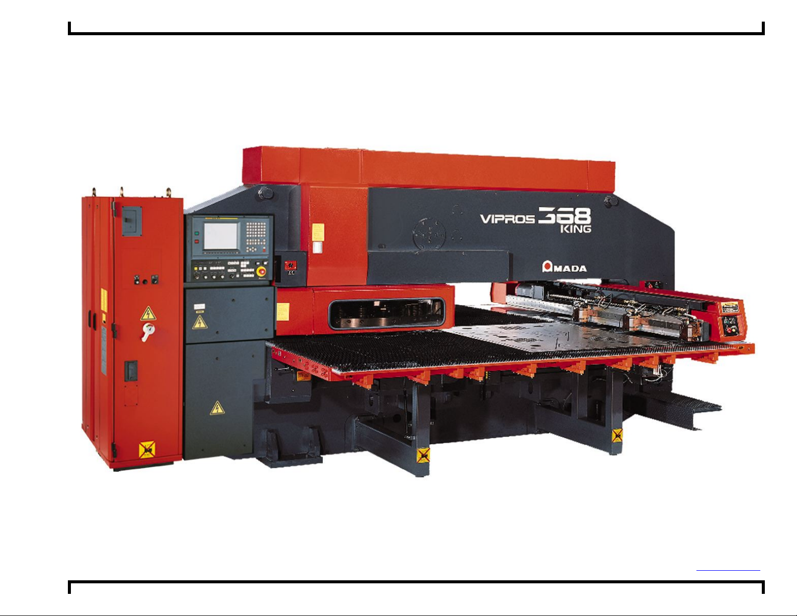
Type II Vipros 368 King with Fanuc 18P Control
Layout Drawings
Amada America I nc.
7025 Firestone Blvd.
Buena Park CA. 90621
Phone: (714) 739 2111
Fax.: (714) 739 4099
Email info@amada.com
Print Date 02/27/01 Revi sion 4.0 This document av ailable on the World W ide Web at http://www.amada.com Page 1 of 10
Page 2
Type II Vipros 368 King With Fanuc 18P Control Layout Drawings ©Amada America Inc.
Warning
! Qualified personnel must complete all work.
! Do not apply power to the Type II Vipros 368 King until an A.E.S.I. (Amada
Engineering and Service Incorporated) Engineer is present and has instructed you
to do so.
! Not all information required to install the Type II Vipros 368 King is included with
this document. Specific details for proper installation are found in the document
Type II Vipros 368 King with Fanuc 18P User Pre-installation Guide available at
the Amada America Internet web site at http://www.amada.com.
! Considerable effort has been made to ensure that this manual is free of
inaccuracies and omissions. However, as we are constantly improving our
product, some of the data contained herein may be out of date. Please check our
Internet site, http://www.amada.com, for the latest release of this document.
Print Date 02/27/01 Revi sion 4.0 This document av ailable on the World W ide Web at http://www.amada.com Page 2 of 10
Page 3
Type II Vipros 368 King With Fanuc 18P Control Layout Drawings ©Amada America Inc.
Contents
Planning the Location of the Type II Vipros 368 King ....................................................................................... 4
Plan View - Type II Vipros 368 King.............................................................................................................. 5
Plan View - Type II Vipros 368 King (shown with optional standard conveyors)............................................ 6
Plan View - Type II Vipros 368 King (shown with optional standard conveyors and MP1530 loader)............ 7
End View - Type II Vipros 368 King............................................................................................................... 8
Elevation View - Type II Vipros 368 King ...................................................................................................... 9
Chiller Placement........................................................................................................................................ 10
Print Date 02/27/01 Revi sion 4.0 This document av ailable on the World W ide Web at http://www.amada.com Page 3 of 10
Page 4

Type II Vipros 368 King With Fanuc 18P Control Layout Drawings ©Amada America Inc.
Planning the Location of the Typ e II Vipros 368 King
The following diagrams provide the details for positioning the Type II Vipros 368 King.
" No obstacles are allowed in the worksheet travel area and the ceiling must be at least 40" above the Type II Vipros 368
King.
" All of the recommended maintenance areas should be used, but at a minimum the doors of the NC unit must be able to be
opened. Any reduction of the listed maintenance areas may increase time and expense of installation and maintenance.
" The Type II Vipros 368 King machine and control must be protected from direct sunlight or other heat sources. Direct
exposure to direct heating sources such as infrared heaters have been shown to affect punch and die alignment.
" The positioning of the SBC EX5.5 Chiller is very flexible.
Print Date 02/27/01 Revi sion 4.0 This document av ailable on the World W ide Web at http://www.amada.com Page 4 of 10
Page 5

Type II Vipros 368 King With Fanuc 18P Control Layout Drawings ©Amada America Inc.
Plan View - Type II Vipros 368 King
Electrical Requirements
Vipros 368 King Type II
E1
230 / 460 / 3 / 60 ±10% 28 kVA
70 amps @ 230 / 3 / 60 VAC
35 amps @ 460 / 3 / 60 VAC
SBC EX5.5 Chiller
E2
230 or 460 / 3 / 60 ±10% 15 kVA
37 amps @ 230 / 3 / 60 VAC
19 amps @ 460 / 3 / 60 VAC
Compressed Air Requirements
Vipros 368 King Type II
A1
Operator Control Station
37"
80 psi @ 8.8 ft³/min.
57"
Chiller Unit
(position variable)
E2
59"
Hydraulic Power Unit
30"
17"
VIPROS 368 King Centerline
11"
12" 12"12"
scale
351.2" Recommended Safety / Maintenance Area 40" From All Components
Y-Axis Zero
108.9"
60." Work Zone
Track 200 Centerline
222.7" Machine Length
120" Travel Area 60" Material
Additional Support Tables Required
VIPROS 368 King
Additional Support Tables Required
A1
E3
E1
81.1" to edge of table 81.1" to edge of table
162.2" Machine Width
314.96" Travel Area 157.48" Material
410.9" Recommended Safety / Maintenance Area 40" From All Components
Print Date 02/27/01 Revi sion 4.0 This document av ailable on the World W ide Web at http://www.amada.com Page 5 of 10
Page 6

Type II Vipros 368 King With Fanuc 18P Control Layout Drawings ©Amada America Inc.
Plan View - Type II Vipros 368 King
Electrical Requirements
Vipros 368 King Type II
E1
230 / 460 / 3 / 60 ±10% 28 kVA
70 amps @ 230 / 3 / 60 VAC
35 amps @ 460 / 3 / 60 VAC
SBC EX5.5 Chiller
E2
230 or 460 / 3 / 60 ±10% 15 kVA
37 amps @ 230 / 3 / 60 VAC
19 amps @ 460 / 3 / 60 VAC
V368 Standard Conveyor 1
E3
208 - 230 / 460 / 3 / 60 ±10% .8 kVA
2.1 amps @ 208 / 3/ 60 VAC
2.0 amps @ 230 / 3 / 60 VAC
1.0 amps @ 460 / 3 / 60 VAC
V368 Standard Conveyor 2
E4
208 - 230 / 460 / 3 / 60 ±10% .8 kVA
2.1 amps @ 208 / 3/ 60 VAC
2.0 amps @ 230 / 3 / 60 VAC
Compressed Air Requirements
Vipros 368 King Type II
A1
Operator Control Station
12" 12"12"
scale
80 psi @ 8.8 ft³/min.
37"
108.9"
222.7" Machine Length
57"
Chiller Unit
(position variable)
Y-Axis Zero
60." Work Zone
Track 200 Centerline
(shown with optional standard conveyors)
17"
11"
VIPROS 368 King Centerline
VIPROS 368 King
E4
Conveyor 1
E2
59"
Hydraulic Power Unit
30"
Additional Support Tables Required
351.2" Recommended Safety / Maintenance Area 40" From All Components
120" Travel Area 60" Material
Additional Support Tables Required
A1
E3
Conveyor 2
E1
81.1" to edge of table 81.1" to edge of table
162.2" Machine Width
314.96" Travel Area 157.48" Material
410.9" Recommended Safety / Maintenance Area 40" From All Components
Access Required for
Scrap / Slug Removal
Print Date 02/27/01 Revi sion 4.0 This document av ailable on the World W ide Web at http://www.amada.com Page 6 of 10
Page 7

Type II Vipros 368 King With Fanuc 18P Control Layout Drawings ©Amada America Inc.
530
h
Plan View - Type II Vipros 368 King
Electrical Requirements
Vipros 368 King Type II
E1
230 / 460 / 3 / 60 ±10% 28 kVA
70 amps @ 230 / 3 / 60 VAC
35 amps @ 460 / 3 / 60 VAC
SBC EX5.5 Chiller
E2
230 or 460 / 3 / 60 ±10% 15 kVA
37 amps @ 230 / 3 / 60 VAC
19 amps @ 460 / 3 / 60 VAC
V368 Standard Conveyor 1
E3
208 - 230 / 460 / 3 / 60 ±10% .8 kVA
2.1 amps @ 208 / 3/ 60 VAC
2.0 amps @ 230 / 3 / 60 VAC
1.0 amps @ 460 / 3 / 60 VAC
V368 Standard Conveyor 2
E4
208 - 230 / 460 / 3 / 60 ±10% .8 kVA
2.1 amps @ 208 / 3/ 60 VAC
2.0 amps @ 230 / 3 / 60 VAC
1.0 amps @ 460 / 3 / 60 VAC
E5
MP1530 Loader
200 / 3 / 60 ±10%, 10 Kva
To operate at 230 / 460 VAC a step up
transformer is required with the following
service is required
29 amps @ 200 / 3 / 60 VAC
26 amps @ 230 / 3 / 60 VAC
13 amps @ 460 / 3 / 60 VAC
Compressed Air Requirements
Vipros 368 King Type II
A1
MP1530 Loader
A2
Operator Control Station
80 psi @ 8.8 ft³/min.
75 psi @ 31.8 ft³/min.
12" 12"12"
scale
37"
222.7" Machine Length
351.2" Recommended Safety / Maintenance Area 40" From All Components
57"
Chiller Unit
(position variable)
Y-Axis Zero
108.9"
60." Work Zone
Track 200 Centerline
120" Travel Area 60" Material
Additional Support Tables Required
E2
(shown with optional standard conveyors and MP1530 loader)
59"
Hydraulic Power Unit
30"
17"
MP1530
Xformer
E5
A2
VIPROS 368 King Centerline
11"
VIPROS 368 King
Additional Support Tables Required
E4
Conveyor 1
A1
Access Required For Material / Parts Removal
E3
E1
Conveyor 2
Access Required for
Scrap / Slug Removal
MP1530
23.8" MP1530 Loader Length
145.8" 78.0"
81.1" to edge of table 81.1" to edge of table
162.2" Machine Width
314.96" Travel Area 157.48" Material
498.2" Recommended Safety / Maintenance Area 40" From All Components
82.1" to edge of loader 162.7" MP1
Loader Widt
Print Date 02/27/01 Revi sion 4.0 This document av ailable on the World W ide Web at http://www.amada.com Page 7 of 10
Page 8

Type II Vipros 368 King With Fanuc 18P Control Layout Drawings ©Amada America Inc.
End View - Type II Vipros 368 King
104.38"
56.06"
Floor Line
43.31"*
Material Pass
Line
7.44"
78.74" X axis Load Position
*Material Pass Line will vary with installed optional equipment
131.89" Shipping Width w/o Crate
14.76"
29.53"
35.43"
162.2"
12"
12"
scale
12"
Print Date 02/27/01 Revi sion 4.0 This document av ailable on the World W ide Web at http://www.amada.com Page 8 of 10
Page 9

Type II Vipros 368 King With Fanuc 18P Control Layout Drawings ©Amada America Inc.
Elevation View - Type II Vipros 368 King
Center of Turret
Center T rac k 200 T ool
69.68" 19.70" 1.18"47.25"60.0"
Y Axis 0"
29.5"
Hydralic
Power Unit
43.31"*
Material
Pass Line
24.41" 1.64"
*Material Pass Line will vary with installed options
41.63" 41.24"
9.84"
222.76"
7.1"
14."
113.39"
196.65"
47.2"
11"
41.63"62.30"
12"12"12"
scale
Print Date 02/27/01 Revi sion 4.0 This document av ailable on the World W ide Web at http://www.amada.com Page 9 of 10
Page 10

Type II Vipros 368 King With Fanuc 18P Control Layout Drawings ©Amada America Inc.
Chiller Placement
Maximum Travel Area
for Material Size of
(X)157.5" x (Y)60"
Under normal operating conditions the Chiller may be
placed against walls as shown. For maintenance
purposes access to all sides may be required. 60"
overhead clearence required. Chiller may be located
up to 50ft from Hydraulic Unit. Chiller is not designed
for outdoor placement.
6"
Chiller Unit
Hydraulic Unit
(Location Fixed)
Two 15ft supplied water lines
Air Flow
Print Date 02/27/01 Revi sion 4.0 This document av ailable on the World W ide Web at http://www.amada.com Page 10 of 10
6"
 Loading...