

Page 1
Vipros 358 King User Pre-installation Guide Amada America Inc.
Vipros 358 King User Pre-installation Guide
Print Date 11/05/97 Page 1 of 41
This document available on the World Wide Web at http://amada.com/support/pdf/v358kuig.pdf
Page 2

Vipros 358 King User Pre-installation Guide Amada America Inc.
Warning
Qualified personnel must complete al l work.
Do not apply power to the Vipros 358 King until an A.E.S.I. (Amada
Engineering and Service Incorporated) Engineer is present and has
instructed you to do so.
Print Date 11/05/97 Page 2 of 41
This document available on the World Wide Web at http://amada.com/support/pdf/v358kuig.pdf
Page 3

Vipros 358 King User Pre-installation Guide Amada America Inc.
Contents
Contents....................................................................................................................................................3
Introduction ...............................................................................................................................................5
Motion Package Specifications.................................................................................................................6
Punching System Specifications...............................................................................................................7
58 Station - 4 Auto-Index Turret Configuration...................................................................................8
Fanuc O4PC CNC Controller....................................................................................................................9
Supply Requirem ent s ..............................................................................................................................10
Installing the Electrical Power Supply...............................................................................................11
Installing the Air Supply.....................................................................................................................12
Planning the Location of the Vipros 358 King.........................................................................................13
Lifting the Machine ............................................................................................................................14
Machine Dimensions - Plan View......................................................................................................15
Machine Dimensions - Elevation View..............................................................................................16
Machine Dimensions - End View ......................................................................................................17
Maintenance Areas ...........................................................................................................................18
The Chiller...............................................................................................................................................19
Chiller Placement..............................................................................................................................20
Connections.......................................................................................................................................21
Foundation Requirements.......................................................................................................................22
Machine Anchoring Requirements..........................................................................................................23
Print Date 11/05/97 Page 3 of 41
This document available on the World Wide Web at http://amada.com/support/pdf/v358kuig.pdf
Page 4

Vipros 358 King User Pre-installation Guide Amada America Inc.
Floor J-bolt Mounting Hole Detail (saw cut hole)..............................................................................23
Floor J-bolt Mounting Hole Plan View (saw cut hole).......................................................................24
Alternative Floor J-bolt Mounting Hole Detail (Core Drill).................................................................25
Alternative J-bolt Mounting Method Plan View (Core Drill)...............................................................26
Floor J-bolt Mounting Procedure.......................................................................................................27
Foundation Mo unti ng P roc edu re ............................................................................................................29
Foundation J-bolt Detail ....................................................................................................................29
Foundation Plan View .......................................................................................................................30
Foundation Elevation View................................................................................................................31
Removing the Protective Coating...........................................................................................................32
Machine Leveling....................................................................................................................................33
Rocking Test......................................................................................................................................34
Floor Condition: Crowning.................................................................................................................35
Floor Condition: Slope.......................................................................................................................36
Leveling Procedure ...........................................................................................................................37
Print Date 11/05/97 Page 4 of 41
This document available on the World Wide Web at http://amada.com/support/pdf/v358kuig.pdf
Page 5

Vipros 358 King User Pre-installation Guide Amada America Inc.
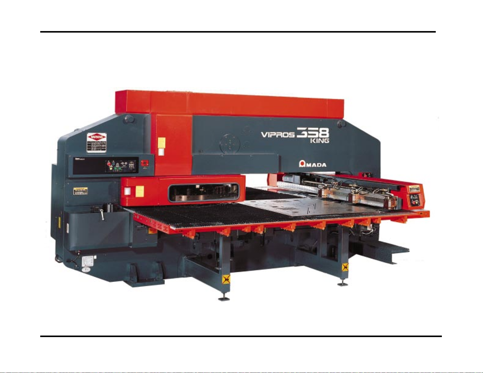
Introduction
This manual describes the tasks that the purchaser of a Vipros 358 King must complete before calling the service
organization to complete the installation and operator training.
An overview of the preparations is as follows:
Plan the location of the Vipros 358 King in the shop, taking into account all the maintenance areas indicated
on the floor plan.
Prepare the Vipros 358 King floor area as required.
Uncrate the Vipros 358 King and Fanuc O4PC control and place them on the floor.
Install the air supply.
Install the electri cal supply.
Remove the protective coating from the surface of the Vipros 358 King.
Anchor the Machine to the floor or foundation using the apropriate method described in this document
Note: It is the purchaser’s responsibility to install any safety devices to ensure the safety area.
Print Date 11/05/97 Page 5 of 41
This document available on the World Wide Web at http://amada.com/support/pdf/v358kuig.pdf
Page 6

Vipros 358 King User Pre-installation Guide Amada America Inc.
Motion Package Specifications
Travel Method X and Y axes work piece movement
Control Method X, Y, T & C
Drive Motors Fanuc AC Servo (X, Y, T, C)
Maximum Sheet Size 50.000" (Y) x 157.480" (X) with one
repositioning cycle
Maximum Sheet Thickness 0.125"
Maximum Material Weight 110 lb.
Maximum Axis Travel 78.740"(X) x 50.000"(Y)
Max. Linear Table Speed 3150 IPM
Punching Accuracy ±0.004"
Positioning Accuracy ±0.001"
Repeatability ±0.001"
Print Date 11/05/97 Page 6 of 41
This document available on the World Wide Web at http://amada.com/support/pdf/v358kuig.pdf
Page 7
Vipros 358 King User Pre-installation Guide Amada America Inc.
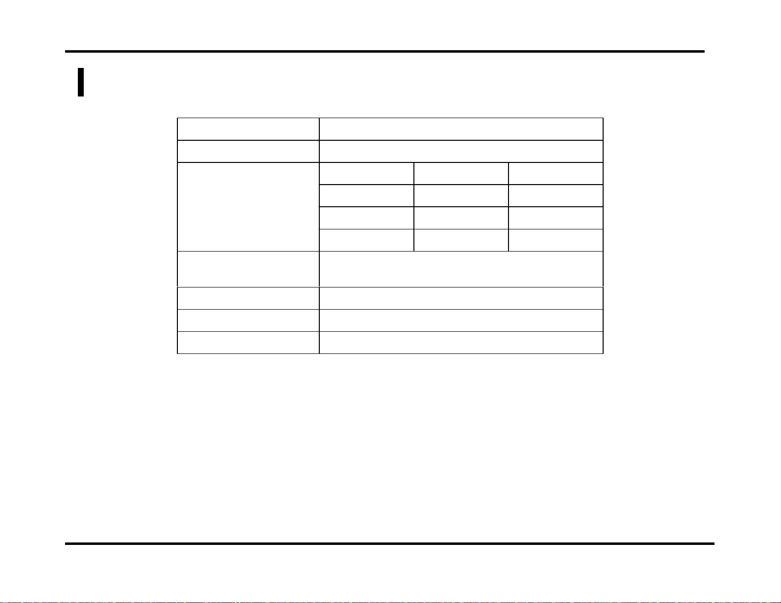
Punching System Specifications
Press Capacity 33 Tons
Press Stroke 1.256"
Stroke Rate (X/Y) Stroke Length Pitch Stroke Rate
0.315" 1.000" 300/375
0.178" 1.000" 375/375
0.178" 0.078" 600/600
Maximum Hole
Diameter
Tool Type Amada Thick Turret
Turret Rotation Speed 25 RPM
Turret Capacity 58 Stations (4 auto-index)
4.500"
Print Date 11/05/97 Page 7 of 41
This document available on the World Wide Web at http://amada.com/support/pdf/v358kuig.pdf
Page 8
Vipros 358 King User Pre-installation Guide Amada America Inc.
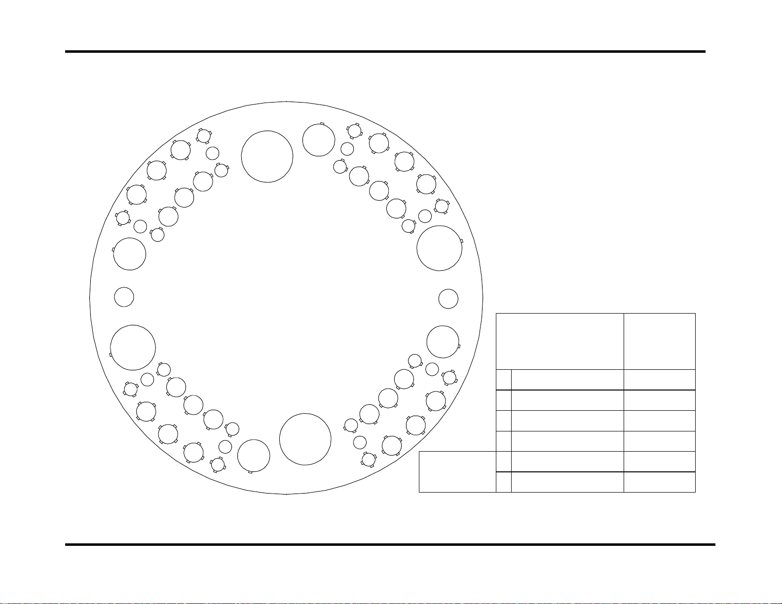
58 Station - 4 Auto-Index Turret Configuration
201
305
202
A/I
307
258
357
204
256
354
309
106
103
155
153
352
311
108
110
314
213
115
A/I
112
1200mm disk
216
117
58 STATION
4 AUTO INDEX
VIPROS 358 KING VIPROS 368 KING
VIPROS 558 VIPROS 568
PEGA 358S
151
350
149
146
247
245
348
144
A/I
141
242
218
120
343
319
139
321
122
137
124
126
132
340
323
135
325
227
229
231
233
336
338
Auto Index
328
A/I
334
230
A
B
C
D
B
E
Maximum
Size Round
½" (12.7mm)
1¼" (31.7mm)
2" (50.8mm )
3½" (88.9mm)
1¼" (31.7mm)
4½" (114.3mm)
Number of
Stations
(Keyed)
24 (16)
24 (24)
4 (4)
2 (2)
2 (2)
2 (2)
Print Date 11/05/97 Page 8 of 41
This document available on the World Wide Web at http://amada.com/support/pdf/v358kuig.pdf
Page 9
Vipros 358 King User Pre-installation Guide Amada America Inc.
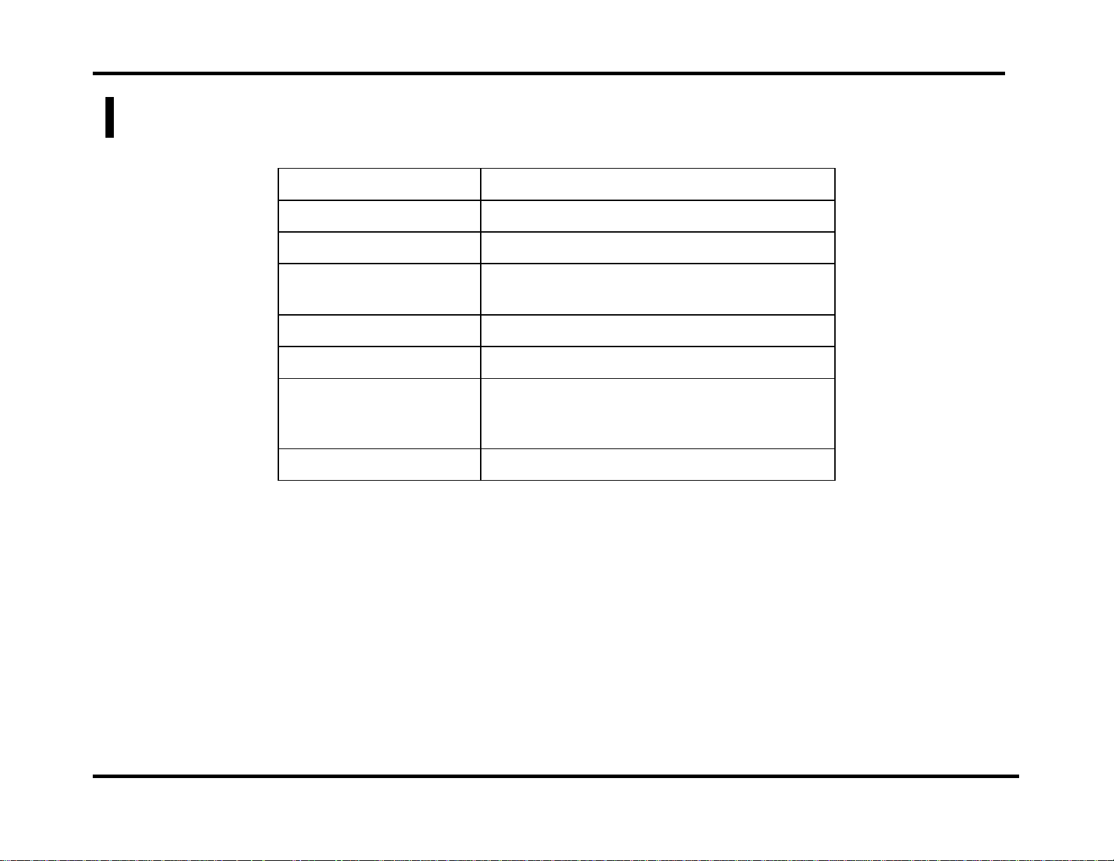
Fanuc O4PC CNC Controller
Model Fanuc O4PC
Control Function X, Y, T & C
Input Method MDI, Paper Tape, DNC
Minimum Command
Unit
Minimum Travel Unit 0.001" (X, Y) .010 (C)
Operating Modes Automatic, MDI & Manual
Display Modes
Interlock Displays Oil Temperature, Door Open
0.001" (X, Y) .010 (C)
Program Contents, Position Information,
Program Check, Parameters, Tool Hit
Counter, Self Diagnostics
Print Date 11/05/97 Page 9 of 41
This document available on the World Wide Web at http://amada.com/support/pdf/v358kuig.pdf
Page 10

Vipros 358 King User Pre-installation Guide Amada America Inc.
Supply Requirements
Electrical Power Supply Vipros 358 King
SBC-5.5 Chiller*
Air Supply 80 psi @ 8.8 ft³/min.
*Voltage must be specified when machine is ordered
230 / 460 3ph ±10%, 28 kVA
230 or 460 3ph ±10%, 15 kVA
Print Date 11/05/97 Page 10 of 41
This document available on the World Wide Web at http://amada.com/support/pdf/v358kuig.pdf
Page 11
Vipros 358 King User Pre-installation Guide Amada America Inc.
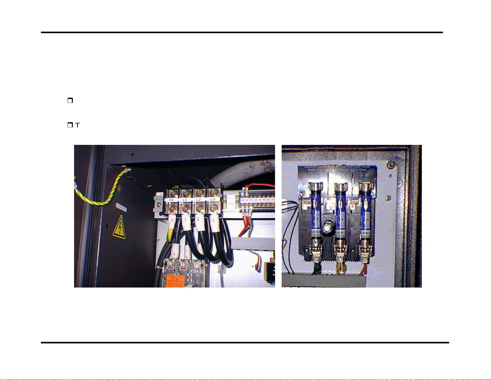
Installing the Electrical Power Supply
The Vipros 358 King requires two electrical power sources. The first power source is supplied to the Fanuc O4PC
control. The Fanuc O4PC control should be supplied from a power line separate from those used for welding machines
or other machines that produce electrical noise. The second source is connected to the SBC-5.5 chiller.
The Vipros 358 King electrical inlet is 60" above floor level inside the magnetic enclosure located to the rear of
the Fanuc O4PC control.
The SBC-5.5 chiller electrical inlet is 48" above floor level at the end of the chiller.
Vipros King SBC 5.5 Chiller
Print Date 11/05/97 Page 11 of 41
This document available on the World Wide Web at http://amada.com/support/pdf/v358kuig.pdf
Page 12
Vipros 358 King User Pre-installation Guide Amada America Inc.
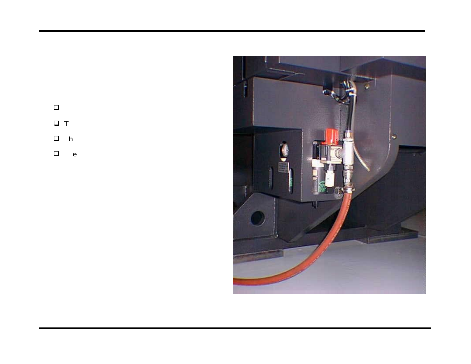
Installing the Air Supply
The Vipros 358 King must be connected to a
compressed air system by hose or pipe. The
compressed air must be clean and dry.
Please note the following:
The minimum inner pipe diameter is ½".
The air pressure required is 80 psi.
The air volume required is 8.8 ft³/min.
The air inlet is approximately 16" above the floor
level at the rear of the Vipros 358 King.
Print Date 11/05/97 Page 12 of 41
This document available on the World Wide Web at http://amada.com/support/pdf/v358kuig.pdf
Page 13

Vipros 358 King User Pre-installation Guide Amada America Inc.
Planning the Location of the Vipros 358 King
The following diagrams provide the details for positioning the Vipros 358 King.
No obstacles are allowed in the worksheet travel area and the ceiling must be at least 40" above the top of
the Vipros 358 King.
All of the maintenance areas recommended should be used, but at a minimum you must ensure that the
doors of the Fanuc O4PC CNC unit can be opened.
The Vipros 358 King, Fanuc O4PC control, and SBC-5.5 chiller must be protected from direct sunlight or
other heat sources.
The floor must be of sufficent quailty to addiquitly support the wieght of the machine. See
Procedure
for details.
Floor Mounting
Print Date 11/05/97 Page 13 of 41
This document available on the World Wide Web at http://amada.com/support/pdf/v358kuig.pdf
Page 14

Vipros 358 King User Pre-installation Guide Amada America Inc.
Lifting the Machine
Machine Weight 16 tons.
Lifting lugs front and rear of
Machine Frame.
This cover
may need to
be removed
121."
VIPROS
This cover
may need to
be removed
358
KING
Print Date 11/05/97 Page 14 of 41
This document available on the World Wide Web at http://amada.com/support/pdf/v358kuig.pdf
Page 15

Vipros 358 King User Pre-installation Guide Amada America Inc.
Machine Dimensions - Plan View
Print Date 11/05/97 Page 15 of 41
This document available on the World Wide Web at http://amada.com/support/pdf/v358kuig.pdf
Page 16

Vipros 358 King User Pre-installation Guide Amada America Inc.
Machine Dimensions - Elevation View
Material
Pass
Line
96.5"
39.6"
Floor Level
1.3"
11.4"
45.5"
38.3"
Turret Center
62.2"
55.1"
37.4"38.0"
19.7"
9.8"
103.1"
179.1"
Punch Center
7.1"
50.0"
8.3"
27.6"
Y Axis Zero
38.0"55.9"
19.7"
1.2"
Hydraulic
Unit
CNC Unit
55.2"
63.0"
Print Date 11/05/97 Page 16 of 41
This document available on the World Wide Web at http://amada.com/support/pdf/v358kuig.pdf
Page 17

Vipros 358 King User Pre-installation Guide Amada America Inc.
Machine Dimensions - End View
Print Date 11/05/97 Page 17 of 41
This document available on the World Wide Web at http://amada.com/support/pdf/v358kuig.pdf
Page 18

Vipros 358 King User Pre-installation Guide Amada America Inc.
Maintenance Areas
81.1"
Print Date 11/05/97 Page 18 of 41
This document available on the World Wide Web at http://amada.com/support/pdf/v358kuig.pdf
Page 19

Vipros 358 King User Pre-installation Guide Amada America Inc.
The Chiller
The Chiller Unit is very important to the reliable operation of the Vipros 358 King.
The Chiller must be placed so that an adequate flow of air is maintained.
The position of the Chiller is flexible. The Vipros 358 King is supplied with two (2) fifteen-foot lengths of
hose to connect the Chiller to the Hydraulic Unit. The customer may supply a longer length of hose if
required.
Under normal operating conditions the Chiller may be placed against walls as shown. However for
maintenance purposes access to all sides of the Chiller may be required.
The Chiller must have a minimum of 60" of clearance above the Chiller for proper airflow.
Print Date 11/05/97 Page 19 of 41
This document available on the World Wide Web at http://amada.com/support/pdf/v358kuig.pdf
Page 20

Vipros 358 King User Pre-installation Guide Amada America Inc.
,,
yy
{{
Chiller Placement
Print Date 11/05/97 Page 20 of 41
This document available on the World Wide Web at http://amada.com/support/pdf/v358kuig.pdf
Page 21

Vipros 358 King User Pre-installation Guide Amada America Inc.
Connections
Hydraulic Unit Chiller
Print Date 11/05/97 Page 21 of 41
This document available on the World Wide Web at http://amada.com/support/pdf/v358kuig.pdf
Page 22

Vipros 358 King User Pre-installation Guide Amada America Inc.
Foundation Requirements
The Vipros 358 King does not require a special foundation to perform as expected, however there are minimum
requirements that an existing floor must meet in order to assure machine reliability and tool life. If the existing floor
does not meet the following minimum requirements, plans for a recommended foundation are given in the section
Foundation Mounting Procedure
The minimum acceptable floor conditions to assure a successful installation are:
The area of the floor where the machine frame is to be located must be a single, homogeneous slab in good
condition. There must be no cracks or other signs of deterioration of the floor.
The floor must be 4" to 6" thick.
The floor must be capable of supporting 3.5 tons/ft².
The floor must be level to 0.032"/ft.
If the existing floor meets the minimum requirement list above, it must still be inspected carefully when the anchor
boltholes are cut. Voids under the floor, or wetness (not associated with the hole cutting procedure) should be
considered signs of an inadequate floor and a new machine location or new foundation must be considered.
It is the customer’s responsibility to determine that the floor meets these minimum requirements. Placing the machine
on an inadequate, cracked floor, or straddling seams in a floor may be grounds for voiding the machine warranty!
Amada America, Inc. does not recommend the use of vibration isolating mounts under the machine feet, as these
devices have been shown to increase the vibration within the machine frame, increasing the likelihood of vibration
related problems. Solid leveling devices are acceptable provided they incorporate a means of anchoring the machine
to the floor with the supplied J-bolts.
Print Date 11/05/97 Page 22 of 41
This document available on the World Wide Web at http://amada.com/support/pdf/v358kuig.pdf
Page 23

Vipros 358 King User Pre-installation Guide Amada America Inc.
Machine Anchoring Requirements
To maintain machine reliability, extend tool life, and remain level over an extended period the Vipros 358 King must be
anchored in place on an adequate floor or foundation.
At a minimum the floor must consist of a single, homogeneous slab, level to within 0.032"/ft², and capable of supporting
3.5 tons/ft². It is the purchaser’s responsibility to determine that the floor meets these minimum requirements.
Floor J-bolt Mounting Hole Detail
(saw cut hole)
This machine mounting method should be used only if the
floor is of such quality that it will support the weight of the
machine with the anchor J-bolts used only for maintaining
the location of the machine.
Machi ne Foot
Base Plate
Saw cut hole in foundation
Machine Foot
5.0"
Floor Line
Supplie d J -bolt
24.00"
7.0"
15.75"
5."
10.00"
Print Date 11/05/97 Page 23 of 41
This document available on the World Wide Web at http://amada.com/support/pdf/v358kuig.pdf
Page 24

Vipros 358 King User Pre-installation Guide Amada America Inc.
Floor J-bolt Mounting Hole Plan View (saw cut hole)
Print Date 11/05/97 Page 24 of 41
This document available on the World Wide Web at http://amada.com/support/pdf/v358kuig.pdf
Page 25

Vipros 358 King User Pre-installation Guide Amada America Inc.
Alternative Floor J-bolt Mounting Hole Detail
(Core Drill)
This machine mounting method should only be used if
the floor is of such quality that it will support the weight
of the machine with the anchor J-bolts used only for
maintaining the location of the machine.
10" Diameter Core Drill
hole in existing fl oor
A
Machine Foot
A
Floor Line
Supplied J-bol t
A
Print Date 11/05/97 Page 25 of 41
This document available on the World Wide Web at http://amada.com/support/pdf/v358kuig.pdf
Page 26

Vipros 358 King User Pre-installation Guide Amada America Inc.
Alternative J-bolt Mounting Method Plan View (Core Drill)
Print Date 11/05/97 Page 26 of 41
This document available on the World Wide Web at http://amada.com/support/pdf/v358kuig.pdf
Page 27

Vipros 358 King User Pre-installation Guide Amada America Inc.
Floor J-bolt Mounting Procedure
Step 1. Saw cut or Core drill a hole in the existing floor
and remove the underlying dirt to the required
24" depth.
See
Floor J-bolt Mounting Hole Plan View (saw
cut hole)
Plan View (Core Drill
dimensions of the four anchor holes required.
Step 2. Set base plate over the hole.
or
Alternative J-bolt Mounting Method
for correct layout
Step 3. Set the machine on the base plate.
Print Date 11/05/97 Page 27 of 41
This document available on the World Wide Web at http://amada.com/support/pdf/v358kuig.pdf
Page 28

Vipros 358 King User Pre-installation Guide Amada America Inc.
Step 4. Set the J-bolt through the hole in machine foot;
attach washer and nut to hold J-bolt in place.
Step 5 Pour the Concrete.
Ensure that the J-bolt remains correctly aligned
to the machine frame during the pouring and
hardening time of the concrete.
Ensure that the concrete level is equal to the
floor level
Step 6. To complete the mounting procedure, level the
machine frame by inserting leveling shims
between the machine foot and base plate.
See
Leveling the Machine
procedure.
Print Date 11/05/97 Page 28 of 41
This document available on the World Wide Web at http://amada.com/support/pdf/v358kuig.pdf
section for correct
Page 29

Vipros 358 King User Pre-installation Guide Amada America Inc.
Foundation Mounting Procedure
An ideal foundation is given on the following pages. This foundation must be used if the existing floor cannot meet the
minimum requirements to support the machine.
The foundation must consist of a single, homogeneous slab. The foundation must be level to within 0.032" / ft.
Anchoring the Vipros 358 King to the floor using the anchor-bolts supplied is essential to ensure reliable performance.
Amada generally recommends that the foundation have a minimum load bearing capacity of 3.5 ton/ft2. It is the
purchaser’s responsibility to determine that the foundation meets these requirements.
Please note the following:
The base plates, shims, anchor bolts, nuts, and washers
are shipped with the Vipros 358 King.
The concrete J-bolt pads should be filled after the machine
is placed on the foundation.
Foundation J-bolt Detail
See
J-bolt Mounting Procedure
machine on foundation.
for proper method of mounting
Machine Foot
Foundation Line
Supplied J-bolt
Anchor hole in foundatio n
Machine
Fram e
5.0"
24.00"
7.0"
15.75"
Machine Foot
Base Plate
5."
10.00"
Print Date 11/05/97 Page 29 of 41
This document available on the World Wide Web at http://amada.com/support/pdf/v358kuig.pdf
Page 30

Vipros 358 King User Pre-installation Guide Amada America Inc.
Foundation Plan View
151.1"
96."
48."
48."
24."
103.1"
J-bolt Centerline
Machine Centerline
29.5" J-bolt Centerline
14.75"
Print Date 11/05/97 Page 30 of 41
This document available on the World Wide Web at http://amada.com/support/pdf/v358kuig.pdf
Page 31

Vipros 358 King User Pre-installation Guide Amada America Inc.
Foundation Elevation View
Print Date 11/05/97 Page 31 of 41
This document available on the World Wide Web at http://amada.com/support/pdf/v358kuig.pdf
Page 32

Vipros 358 King User Pre-installation Guide Amada America Inc.
(
)
)
Removing the Protective Coating
The Vipros 358 King must be thoroughly cleaned of protective coating. The sheet metal guards can be removed from
around the turret to allow cleaning of the upper and lower turrets, tool bores and die holders.
Please note the following:
Remove the wrapping paper from the
X and Y-axes ball screws then
remove the protective coating.
Remove the wrapping paper from the
X and Y LM guides then remove the
protective coating, make sure that you
remove the paper from both sides of
the carriage.
Clean die holders one at a time.
Remove a die holder, clean and
replace it before removing the next
die holder. If the die holders are
mixed up, serious turret alignment
problems may occur.
A suitable solvent should be used to
remove the protective coating.
Y AXIS BALL SCREW
UPPER AND LOWER TURRETS
Y AXIS LM GUIDES
X AXIS BALL SCREW
X AXIS LM GUIDES (TOP AND BOTTOM
1 EACH SIDE
Print Date 11/05/97 Page 32 of 41
This document available on the World Wide Web at http://amada.com/support/pdf/v358kuig.pdf
Page 33

Vipros 358 King User Pre-installation Guide Amada America Inc.
Machine Leveling
Proper Machine leveling is critical to the Vipros 358 King performing as designed.
Materials and tools required:
Supplied with the machine:
Assorted thickness machine leveling shim stock
Anchor bolts
Supplied by AESI servi ce:
Spirit level capable of reading 0.0005"/ft
One (1) 12 ton hydraulic bottle jack
Not supplied:
Additional shim stock of 0.005" thickness may be required to achieve a properly leveled machine.
Print Date 11/05/97 Page 33 of 41
This document available on the World Wide Web at http://amada.com/support/pdf/v358kuig.pdf
Page 34

Vipros 358 King User Pre-installation Guide Amada America Inc.
Rocking Test
After the machine frame has been leveled the use of the following G-code is necessary to determine that the machine
frame is properly leveled and balanced.
Should the machine frame vibrate or move excessively during the rocking test the machine frame must be re-leveled
using the procedure in this manual.
Should the proper leveling technique not eliminate the excessive frame motion, consideration must be given to
relocation of the machine or replacement of the existing floor with an adequate foundation.
G92 X78.740 Y50.000
G06 A.100B0
N1
G91 X-.250 T
X.250
M97 P1
G50
(Use any valid tool number)
TTT
Print Date 11/05/97 Page 34 of 41
This document available on the World Wide Web at http://amada.com/support/pdf/v358kuig.pdf
Page 35

Vipros 358 King User Pre-installation Guide Amada America Inc.
Floor Condition: Crowning
The flatness of the floor plays an important step in the
leveling procedure of the machine. To properly level the
machine the weight bearing points must be as far from the
centerline of the machine frame as possible.
Should a condition known as crowning exist the weight
bearing points of the machine may not be far enough from
the machine centerline to ensure a stable machine.
Under these conditions a procedure known as
Shimming
should be used.
Half-
To move the weight bearing points further from the
machine centerline the use of half-shims of .125" thick on
top of the base plate as shown is recommended.
After the half-shims are installed and the machine frame
is leveled use the rocking test to determine that the
machine frame is stable enough to allow production
without damaging the machine.
Under extreme conditions the use of half-shims may not
move the machine weight bearing points far enough from
the machine centerline to ensure the machine frame is
stable.
Base Plate
Crowned
Floor
Base Plate
Crowned
Floor
Machine
centerline
Machine Foot
Base Plate
Weight
Bearing Point
Machine
centerline
Machine Foot
Base Plate
Weight Bearing Point
Half-shim
Under these conditions a more suitable location must be
found for the machine, or a new foundation for the
machine will be necessary.
Print Date 11/05/97 Page 35 of 41
This document available on the World Wide Web at http://amada.com/support/pdf/v358kuig.pdf
Page 36

Vipros 358 King User Pre-installation Guide Amada America Inc.
Floor Condition: Slope
The slope of the floor plays an important step in the
leveling procedure of the machine. To properly level the
machine the weight bearing points must be as far from the
centerline of the machine frame as possible.
Should the floor slope excessively the weight bearing
points of the machine may not be far enough from the
machine centerline to ensure a stable machine.
Under these conditions a procedure known as
Shimming
should be used.
Half-
To move the weight bearing points further from the
machine centerline the use of half-shims of .125" thick on
top of the base plate and leveling shims as shown is
recommended.
After the half-shims are installed and the machine frame
is leveled, use the rocking test to determine that the
machine frame is stable enough to allow production
without damaging the machine.
Under extreme conditions the use of half-shims may not
move the machine weight bearing points far enough from
the machine centerline to ensure the machine frame is
stable.
Machine Foot
Base Plate
Weight Bearing Point
Sloped Floor
Machine Foot
Base Plate
Weight Bearing Point
Sloped Floor
Machine
centerline
Base Plate
Shim
Machine
centerline
Shim
Base Plate
Half-shim
Under these conditions a more suitable location must be
found for the machine, or a new foundation for the
machine will be necessary
.
Print Date 11/05/97 Page 36 of 41
This document available on the World Wide Web at http://amada.com/support/pdf/v358kuig.pdf
Page 37

Vipros 358 King User Pre-installation Guide Amada America Inc.
Leveling Procedure
1) Determine the high end of machine frame by placing the spirit
level on the turret to measure the level of the machine frame
in the y-axis.
.0005"/ft
2) Use the bottle jack to lift the low end of the machine frame.
Shim equally between both machine feet and the base plates
until the machine frame measures near level on the y-axis
with the turret end of the machine frame slightly higher than
the carriage end.
Shim Equaly Both Sides
Bottle
Jack
3) Center the bottle jack under the carriage end of the machine
frame.
Lift the machine frame until all weight is off of the machine
feet at the carriage end of the machine frame.
Lift the machine frame as little as possible to take the weight
Remove weight
of machine from
base plates
Bottle
Jack
off of the base plates.
Print Date 11/05/97 Page 37 of 41
This document available on the World Wide Web at http://amada.com/support/pdf/v358kuig.pdf
Page 38

Vipros 358 King User Pre-installation Guide Amada America Inc.
4) With the machine supported on the bottle jack at the carriage
end of the machine frame and the machine feet at the turret
end of the machine frame, place the spirit level on the turret.
.0005"/ft
Measure and record the level of the turret in the x-axis
direction.
Lower the machine frame to place all machine feet in contact
with the leveling shims and base plates.
5) Lift the turret end of the machine frame to allow shimming
between the machine feet and base plates to level the
machine frame in the x-axis direction.
Repeat steps 3 to 5 until the machine frame measures level to
0.0005"/ft in step 4, then continue.
Shim to
level X-axis
Bottle
Jack
6) With the bottle jack supporting the weight of the carriage end
of the machine monitor the level of the turret in the x-axis as
the bottle jack is slowly lowered to place the carriage end
machine feet in contact with the base plates.
Any change in the level indicates that the carriage end of the
machine needs to be leveled.
Remove weight
of machine from
base plates
Bottle
Jack
Print Date 11/05/97 Page 38 of 41
This document available on the World Wide Web at http://amada.com/support/pdf/v358kuig.pdf
Page 39

Vipros 358 King User Pre-installation Guide Amada America Inc.
7) Lift the carriage end of the machine frame to allow shimming
between the machine feet and base plates to level the
carriage end of the machine frame in the x-axis direction.
Repeat steps 6 and 7 until no difference in level is noted when
the machine weight is on or off of the base plates and shims,
then continue.
Shim to
level X-axis
Bottle
Jack
8) With all of the machine feet setting on the shims and base
plates place the spirit level on the turret to measure and note
the level of the machine frame in the y-axis.
.0005"/ft
9) Using the bottle jack lift the low end of the machine frame and
shim equally under both machine feet to level the machine
frame in the y-axis.
Repeat steps 8 to 9 until the machine frame measures level to
0.0005"/ft in the y-axis, then continue.
Shim Equaly Both Sides
Bottle
Jack
Print Date 11/05/97 Page 39 of 41
This document available on the World Wide Web at http://amada.com/support/pdf/v358kuig.pdf
Page 40

Vipros 358 King User Pre-installation Guide Amada America Inc.
10) Run the machine using the rocking test G-code to determine
that the machine frame is leveled adequately. Should
excessive movement of the machine frame be noticed check
for the conditions discussed in
Floor Condition Slope
11) Tighten the anchor bolt nuts to prevent the machine frame
from moving when in use. Monitor the machine level while
tightening the anchor bolts to assure the machine level is not
changed.
12) Lower and lock the outrigger weight support feet in place.
.
Floor Condition Crowning
and
Print Date 11/05/97 Page 40 of 41
This document available on the World Wide Web at http://amada.com/support/pdf/v358kuig.pdf
Page 41

Vipros 358 King User Pre-installation Guide Amada America Inc.
Amada America Inc.
7025 Firestone Blvd.
Buena Park CA. 90621
Phone: (714) 739 2111
Fax: (714) 739 4099
e-mail: info@amada.com
Print Date 11/05/97 Page 41 of 41
This document available on the World Wide Web at http://amada.com/support/pdf/v358kuig.pdf
 Loading...