

Page 1
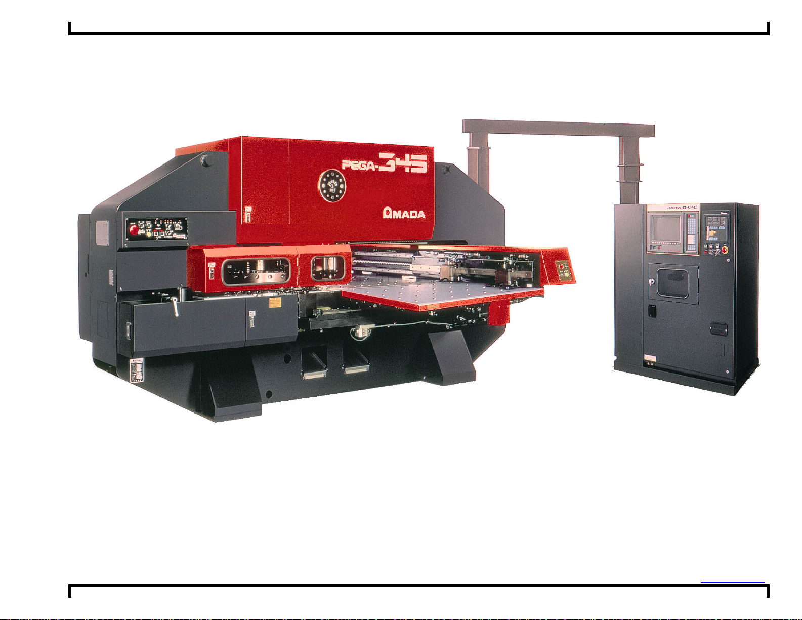
Pega 345 Queen with 04PC Control Layout Drawings ©Amada America, Inc.
Pega 345 Queen with 04PC Control Layout Drawings
Amada America I nc.
7025 Firestone Blvd.
Buena Park CA. 90621
Phone: (714) 739 2111
Fax: (714) 739 4099
Email info@amada.com
Print Date 03/01/2001 Revision 4. 0 This document availabl e on t he World Wide Web at http://www.amada.com Page 1 of 9
Page 2

Pega 345 Queen with 04PC Control Layout Drawings ©Amada America, Inc.
Warning
• Qualified personnel must complete all work.
• Do not apply power to the Pega 345 until an A.E.S.I. (Amada
Engineering and Service Incorporated) Engineer is present and
has instructed you to do so.
• Not all information required for proper installation, of the Pega
345 is included with this document. Specific details for proper
installation are found in the document Pega 345 with 04PC
User Pre-installation Guide available at the Amada America
Internet web site at http://www.amada.com.
• Considerable effort has been made to ensure that this manual
is free of inaccuracies and omissions. However, as we are
constantly improving our product, some of the data contained
herein may be out of date. Please check our Internet site,
http://www.amada.com, for the latest release of this document.
Print Date 03/01/2001 Revision 4. 0 This document availabl e on t he World Wide Web at http://www.amada.com Page 2 of 9
Page 3
Pega 345 Queen with 04PC Control Layout Drawings ©Amada America, Inc.
Table Of Contents
Planning the Location of the Machine..............................................................................................................................................4
Plan View - Pega 345 Queen...........................................................................................................................................................5
Plan View - Pega 345 Queen with V345hs Conveyor......................................................................................................................6
Plan View - Pega 345 Queen with V345hs Conveyor and MP1225 Loader.....................................................................................7
End View - Pega 345 Queen............................................................................................................................................................8
Elevation View - Pega 345 Queen...................................................................................................................................................9
Print Date 03/01/2001 Revision 4. 0 This document availabl e on t he World Wide Web at http://www.amada.com Page 3 of 9
Page 4

Pega 345 Queen with 04PC Control Layout Drawings ©Amada America, Inc.
Planning the Location of the Machine
The following diagrams provide the details for positioning your new machine.
! Not all information required for proper installation, of the Pega 345 is included with this document. Specific details for
proper installation are found in the document Pega 345 with 04PC User Pre-installation Guide available at the Amada
America Internet web site at http://www.amada.com.
! No obstacles are allowed in the worksheet travel area and the ceiling must be at least 40" above the Pega 345 Queen.
! All of the Recommended Safety / Maintenance areas should be used, but you must at least ensure that the doors of the
04PC control unit can be opened. Any reduction of the Recommended Safety / Maintenance areas may increase the
possibility of personnel injury and increase the time and cost of installation or maintenance.
! The Pega 345 Queen and 04PC control must be protected from direct sunlight or other heat sources. Exposure to direct
heating sources such as infrared heaters have been shown to affect punch and die alignment.
Print Date 03/01/2001 Revision 4. 0 This document availabl e on t he World Wide Web at http://www.amada.com Page 4 of 9
Page 5

Pega 345 Queen with 04PC Control Layout Drawings ©Amada America, Inc.
05
C
C
56"
5
3"
h
Plan View - Pega 345 Queen
Electrical Requirements
E1
Pega 345 Queen
230 / 460 / 3 / 60 ±10% 18 kVA
46 amps @ 230 / 3 / 60 VAC
23 amps @ 460 / 3 / 60 VAC
.21"
27.
ontrol
Compressed Air Requirements
A1
Pega 345 80 psi @ 8.8 ft3/min.
Operator Control Station
12" 12"
Scale
12"
58.47"
39.37" Work Range
162.52" Pega 345 Queen Length
310.84" Recomended Safety / Maintenance Area 40" From All Components
80" Maximum Travel Area 40" Material
"
4.
Y-axis Zero
Optional Material Support
Tables Required
Power Supply
19.10"
A1
11.56"
E1
Pega 345Q
4P
" Minimum
45
56" Maximum
Optional Material Support
Tables Required
55.12"
109.85" Pega 345 Queen Widt
200" Maximum Travel Area 100" Material
280.00" Recomended Safety / Maintenance Area 40" From All Components
Print Date 03/01/2001 Revision 4. 0 This document availabl e on t he World Wide Web at http://www.amada.com Page 5 of 9
4.7
Page 6

Pega 345 Queen with 04PC Control Layout Drawings ©Amada America, Inc.
"
5
this area fo
0
05
C
C
56"
5
h
Plan View - Pega 345 Queen with V345hs Conveyor
Electrical Requirements
E1
Pega 345 Queen
230 / 460 / 3 / 60 ±10% 18 kVA
46 amps @ 230 / 3 / 60 VAC
23 amps @ 460 / 3 / 60 VAC
E2
P345hs Conveyor
208 - 230 / 460 / 3 / 60 ±10% .8 kVA
2.1 amps @ 208 / 3/ 60 VAC
2.0 amps @ 230 / 3 / 60 VAC
1.0 amps @ 460 / 3 / 60 VAC
Compressed Air Requirements
A1
Pega 345
80 psi @ 8.8 ft3/min.
Operator Control Station
19.10"
11.56"
27.
ontrol
.21"
4P
E1
12" 12"
Scale
12"
58.47"
" Minimum
45
56" Maximum
Pega 345Q
Y-axis Zero
Optional Material Support
" Material
39.37" Work Range
162.52" Pega 345 Queen Length
" Maximum Travel Area 4
"
4.
383.84" Recomended Safety / Maintenance Area 40" From All Components
Tables Required
Optional Material Support
Tables Required
A1
73.00"
hs
4
46.77
Access required
r
55.12"
109.85" Pega 345 Queen Widt
200" Maximum Travel Area 100" Material
280.00" Recomended Safety / Maintenance Area 40" From All Components
4.73"
Print Date 03/01/2001 Revision 4. 0 This document availabl e on t he World Wide Web at http://www.amada.com Page 6 of 9
Page 7

Pega 345 Queen with 04PC Control Layout Drawings ©Amada America, Inc.
55.73" To Edge Of MP1225
n
g
C
C
56"
55.12
h
l
0
05
s
Plan View - Pega 345 Queen with V345hs Conveyor and MP1225 Loader
Electrical Requirements
E1
Pega 345 Queen
230 / 460 / 3 / 60 ±10% 18 kVA
46 amps @ 230 / 3 / 60 VAC
23 amps @ 460 / 3 / 60 VAC
E2
P345hs Conveyor
208 - 230 / 460 / 3 / 60 ±10% .8 kVA
2.1 amps @ 208 / 3/ 60 VAC
2.0 amps @ 230 / 3 / 60 VAC
1.0 amps @ 460 / 3 / 60 VAC
E3
MP1225 Loader
200 / 3 / 60 ±10%, 10 Kva
To operate at 230 / 460 VAC a step up
transformer with the following service is
required
29 amps @ 200 / 3 / 60 VAC
26 amps @ 230 / 3 / 60 VAC
13 amps @ 460 / 3 / 60 VAC
Compressed Air Requirements
A1
Pega 345 80 psi @ 8.8 ft3/min.
A2
MP1225 Loader 75 psi @ 31.8 ft3/min.
Operator Control Station
12" 12"
12"
Scale
58.47"
" Material
39.37" Work Range
162.52" Pega 345 Queen Length
" Maximum Travel Area 4
"
4.
383.84" Recomended Safety / Maintenance Area 40" From All Components
Y-axis Zero
Optional Material Support
Tables Required
19.10"
11.56"
A1
27.
ontrol
.21"
0.06
mm
4P
E1
"
45
Pega 345Q
Optional Material Support
MP1225
Xformer
Minimum
A2
56" Maximum
Tables Required
E3
MP1225 Material Load Positio
th
89.63" MP1225 Len
122.11" 67.52"
MP1225
Forklift access required
this area for material / parts
loading / unloading
E2
P345hs
Access required
this area for
slug removal
54.73"
109.85" Pega 345 Queen Widt
200" Maximum Travel Area 100" Materia
377.46" Recomended Safety / Maintenance Area 40" From All Component
141.74" MP1225 Width
Print Date 03/01/2001 Revision 4. 0 This document availabl e on t he World Wide Web at http://www.amada.com Page 7 of 9
Page 8

Pega 345 Queen with 04PC Control Layout Drawings ©Amada America, Inc.
29.53"
55.12"
54.72"
109.84"
79.88"
111.00"
"
S
e
End View - Pega 345 Queen
111.00"
79.88"
35.12"*
Material
Pass Line
29.53"
37.99"
54.72"
109.84"
*Dimension will change with installed options
55.12"
12"12"12
cal
Print Date 03/01/2001 Revision 4. 0 This document availabl e on t he World Wide Web at http://www.amada.com Page 8 of 9
Page 9

Pega 345 Queen with 04PC Control Layout Drawings ©Amada America, Inc.
33
"
95"
9.84"
"
87.60"
99"
33
"162.52"
pth
a
Elevation View - Pega 345 Queen
35.12"*
Material
Pass Line
Floor Line
47.24" Throat De
.47
27.
.37" Work Are
11.02
7.
.47
79.89"
62.99"
27.56"
12" 12"
Scale
Print Date 03/01/2001 Revision 4. 0 This document availabl e on t he World Wide Web at http://www.amada.com Page 9 of 9
 Loading...