

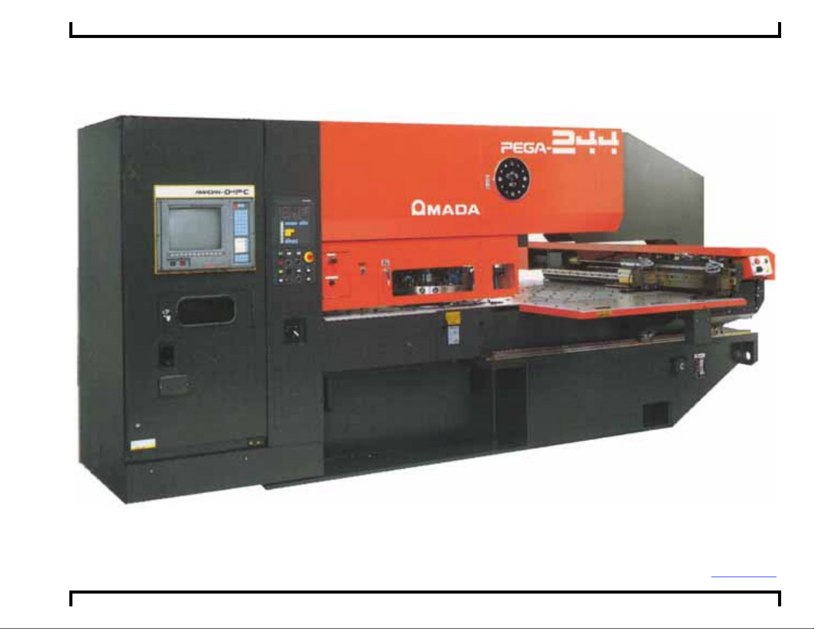
Pega 244N With 04PC Machine Programming Limits ©Amada America, Inc.
Pega 244N With 04PC Machine Programming Limits
Amada America Inc.
7025 Firestone Blvd.
Buena Park, CA 90621
Phone: 714-739-2111
Fax: 714-739-4099
Email Info@amada.com
Print Date 12/18/00 Revision 4.0 Page 1 of 11

Pega 244N With 04PC Machine Programming Limits ©Amada America, Inc.
Table of Contents
Programmable Travel Limits.......................................................................................................................................................... 3
Programmable Feed Rates............................................................................................................................................................ 4
Punching Mode.......................................................................................................................................................................... 4
Punch Confirmation Area / Punching Dead Zone........................................................................................................................... 5
Definitions.................................................................................................................................................................................. 5
Punch Confirmation Area........................................................................................................................................................... 6
Punching Dead Zone................................................................................................................................................................. 7
Material Clamp Locations............................................................................................................................................................... 8
Reposition Limitations.................................................................................................................................................................... 9
Work Chute / Trap Door............................................................................................................................................................... 10
Turret 740mm Disk Thick 24 Station 2 Auto Index....................................................................................................................... 11
Print Date 12/18/00 Revision 4.0 Page 2 of 11
Pega 244N With 04PC Machine Programming Limits ©Amada America, Inc.
Programmable Travel Limits
Y
Track 300
X
Origin Statement
X-axis
Movable Distance
X-axis Origin Y-axis Origin
40.000" 40.945" -.394" to 40.394" -.394" to 41.399" -1.969" to 39.764"
Print Date 12/18/00 Revision 4.0 Page 3 of 11
Y-axis Movable Distance By Track Numbers
Center Track
200 Stations
Track 200
Outer Track
300 Stations

Pega 244N With 04PC Machine Programming Limits ©Amada America, Inc.
Programmable Feed Rates
Punching Mode
F1 = X1968. IPM Y1968. IPM
F2 = X1476. IPM Y1476. IPM
F3 = X984. IPM Y984. IPM
F4 = X492. IPM Y492. IPM
Print Date 12/18/00 Revision 4.0 Page 4 of 11

Pega 244N With 04PC Machine Programming Limits ©Amada America, Inc.
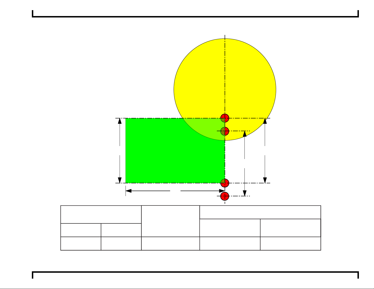
Punch Confirmation Area / Punching Dead Zone.
Definitions
Confirmation Zone = An area that when the confirmation switch is in the on position or it is the first run of the part program
the operator must confirm the punch by pressing the confirmation pushbutton.
Punch Dead Zone = An area that when the confirmation switch is in the on position or it is the first run of the part program
the operator must confirm the punch by pressing the confirmation pushbutton. Punching in this area
with standard tools may damage the material, material clamp, tool, other machine components and
may cause operator injury.
Print Date 12/18/00 Revision 4.0 Page 5 of 11

Pega 244N With 04PC Machine Programming Limits ©Amada America, Inc.
Punch Confirmation Area
Track 200 Punch Confirmation Zone
Track 300 Punch Confirmation Zone
Track 200
5.1"
Track 300
3.5"
6.9" 6.9"
Punch Confirmation Zones are set by
mechanical limit switches and as such may vary
from stated values.
Clamp Centerline
Print Date 12/18/00 Revision 4.0 Page 6 of 11

Pega 244N With 04PC Machine Programming Limits ©Amada America, Inc.
Punching Dead Zone.
T
o
o
l
G
0.400"
T
o
o
l
G
u
d
i
d
e
D
i
a
e
t
e
m
X-axis
Y-axis
r
a a
X- axis Clamp Centerline
To the left of the clamp
To the Right of the clamp
d
u
i
d
e
D
i
a
1.575"
"areas where the punch will contact the material clamp"
r
e
t
e
m
a
Y 0" Edge of Material
T
o
o
l
G
Clamp Sensor
u
1.575"
are calculated in the following manner.
b
Clamp Dead Zones
.400" + a + d/2
d
i
d
e
D
i
a
Clamp position +1.575" + a + b + d/2
r
e
t
e
m
Clamp position -1.575" - a - d/2
d=
b=
a=
.500"
.500"
A
1.020"
B
1.883"
C
3.500"
D
E
4.938"
6.250"
Station Size
Print Date 12/18/00 Revision 4.0 Page 7 of 11

Pega 244N With 04PC Machine Programming Limits ©Amada America, Inc.
Material Clamp Locations
0.400"
Material Clamp
Centerline
Minimum
3.000"
1.575"
1.575"
Material Clamp
1
5.525"
Mimimum Spacing
Clamp Sensor
Material Clamp
Centerline
Material Clamp
Optional
5.525"
Mimimum Spacing
Clamp Sensor
Material Clamp
Centerline
Maximum
37.000"
Y 0" Edge of Material
Clamp Sensor
Material Clamp
Last
Print Date 12/18/00 Revision 4.0 Page 8 of 11

Pega 244N With 04PC Machine Programming Limits ©Amada America, Inc.
Reposition Limitations
When reposi tioning within a Confirmation zone the Confirm ation Button must be pressed to initiate the reposition cycle, as the
material clamps could collide with the repositioning cylinders.
2"
Y
Left
Holddown
15.75"
Track 200 Confirmation Zone 5.1"
Right
Holddown
200
300
15.75"
Track 300 Confirmation Zone 3.6"
Y
Print Date 12/18/00 Revision 4.0 Page 9 of 11

Pega 244N With 04PC Machine Programming Limits ©Amada America, Inc.
Work Chute / Trap Door
Track 300
2.38"
Trap Door/Work Chute
13.78"
6.89"
13.78"
Print Date 12/18/00 Revision 4.0 Page 10 of 11

Pega 244N With 04PC Machine Programming Limits ©Amada America, Inc.
Turret 740mm Disk Thick 24 Statio n 2 Auto Index
This turret configuration
used on the following machine models
Pega 244
307
308
206
310
209
312
211
213
314
315
216
205
204
303
302
Print Date 12/18/00 Revision 4.0 Page 11 of 11
24 Station
2 Auto Index
223
201
324
221
322
218
320
217
319
Auto Index
Maximum
Size Round
A
½"
B
1¼"
C
2"
D
3½"
B
1¼"
12.7mm
31.7mm
50.8mm
88.9mm
31.7mm
Number
Of Stations
(Keyed)
12 (6)
6 (6)
2 (2)
2 (2)
2 (2)
 Loading...