

Page 1

CRC Compiler User Guide
c The CRC Compiler is scheduled for product obsolescence and discontinued
support as described in PDN1304. Therefore, Altera does not recommend use
of this IP in new designs. For more information about Altera’s current IP
offering, refer to Altera’s Intellectual Property website.
101 Innovation Drive
San Jose, CA 95134
www.altera.com
Software Version: 9.1
Document Date: November 2009
Page 2

Copyright © 2009 Altera Corporation. All rights reserved. Altera, The Programmable Solutions Company, the stylized Altera logo, specific device designations, and all other
words and logos that are identified as trademarks and/or service marks are, unless noted otherwise, the trademarks and service marks of Altera Corporation in the U.S. and other
countries. All other product or service names are the property of their respective holders. Altera products are protected under numerous U.S. and foreign patents and pending applications, maskwork rights, and copyrights. Altera warrants performance of its semiconductor products to current specifications in accordance with Altera's standard warranty,
but reserves the right to make changes to any products and services at any time without notice. Altera assumes no responsibility or liability arising out of the application or use of
any information, product, or service described herein except as expressly agreed to in writing by Altera Corporation. Altera customers are advised to obtain the latest version of
device specifications before relying on any published information and before placing orders for products or services
.
UG-CRC01004-1.7
Page 3

Contents
Chapter 1. About This Compiler
Release Information . . . . . . . . . . . . . . . . . . . . . . . . . . . . . . . . . . . . . . . . . . . . . . . . . . . . . . . . . . . . . . . . . . . . . 1–1
Device Family Support . . . . . . . . . . . . . . . . . . . . . . . . . . . . . . . . . . . . . . . . . . . . . . . . . . . . . . . . . . . . . . . . . . . 1–1
Features . . . . . . . . . . . . . . . . . . . . . . . . . . . . . . . . . . . . . . . . . . . . . . . . . . . . . . . . . . . . . . . . . . . . . . . . . . . . . . . . 1–2
General Description . . . . . . . . . . . . . . . . . . . . . . . . . . . . . . . . . . . . . . . . . . . . . . . . . . . . . . . . . . . . . . . . . . . . . 1–3
CRC MegaCore Function Verification . . . . . . . . . . . . . . . . . . . . . . . . . . . . . . . . . . . . . . . . . . . . . . . . . . . . . . 1–3
Performance and Resource Utilization . . . . . . . . . . . . . . . . . . . . . . . . . . . . . . . . . . . . . . . . . . . . . . . . . . . . . . 1–3
Installation and Licensing . . . . . . . . . . . . . . . . . . . . . . . . . . . . . . . . . . . . . . . . . . . . . . . . . . . . . . . . . . . . . . . . 1–4
OpenCore Plus Evaluation . . . . . . . . . . . . . . . . . . . . . . . . . . . . . . . . . . . . . . . . . . . . . . . . . . . . . . . . . . . . . 1–5
OpenCore Plus Time-Out Behavior . . . . . . . . . . . . . . . . . . . . . . . . . . . . . . . . . . . . . . . . . . . . . . . . . . . . . . 1–5
Chapter 2. Getting Started
Design Flow . . . . . . . . . . . . . . . . . . . . . . . . . . . . . . . . . . . . . . . . . . . . . . . . . . . . . . . . . . . . . . . . . . . . . . . . . . . . 2–1
CRC Compiler Walkthrough . . . . . . . . . . . . . . . . . . . . . . . . . . . . . . . . . . . . . . . . . . . . . . . . . . . . . . . . . . . . . . 2–1
Create a New Quartus II Project . . . . . . . . . . . . . . . . . . . . . . . . . . . . . . . . . . . . . . . . . . . . . . . . . . . . . . . . . 2–2
Launch the MegaWizard Plug-In Manager . . . . . . . . . . . . . . . . . . . . . . . . . . . . . . . . . . . . . . . . . . . . . . . 2–3
Parameterize . . . . . . . . . . . . . . . . . . . . . . . . . . . . . . . . . . . . . . . . . . . . . . . . . . . . . . . . . . . . . . . . . . . . . . . . . 2–3
Set Up Simulation . . . . . . . . . . . . . . . . . . . . . . . . . . . . . . . . . . . . . . . . . . . . . . . . . . . . . . . . . . . . . . . . . . . . . 2–4
Generate Files . . . . . . . . . . . . . . . . . . . . . . . . . . . . . . . . . . . . . . . . . . . . . . . . . . . . . . . . . . . . . . . . . . . . . . . . 2–5
Simulate the Design . . . . . . . . . . . . . . . . . . . . . . . . . . . . . . . . . . . . . . . . . . . . . . . . . . . . . . . . . . . . . . . . . . . . . 2–6
Compile the Design . . . . . . . . . . . . . . . . . . . . . . . . . . . . . . . . . . . . . . . . . . . . . . . . . . . . . . . . . . . . . . . . . . . . . . 2–6
Program a Device . . . . . . . . . . . . . . . . . . . . . . . . . . . . . . . . . . . . . . . . . . . . . . . . . . . . . . . . . . . . . . . . . . . . . . . 2–6
Chapter 3. Functional Description
Functional Overview . . . . . . . . . . . . . . . . . . . . . . . . . . . . . . . . . . . . . . . . . . . . . . . . . . . . . . . . . . . . . . . . . . . . 3–1
CRC Generator . . . . . . . . . . . . . . . . . . . . . . . . . . . . . . . . . . . . . . . . . . . . . . . . . . . . . . . . . . . . . . . . . . . . . . . . . . 3–1
CRC Checker . . . . . . . . . . . . . . . . . . . . . . . . . . . . . . . . . . . . . . . . . . . . . . . . . . . . . . . . . . . . . . . . . . . . . . . . . . . 3–3
Multi-Channel Operation . . . . . . . . . . . . . . . . . . . . . . . . . . . . . . . . . . . . . . . . . . . . . . . . . . . . . . . . . . . . . . . . . 3–4
Parameters . . . . . . . . . . . . . . . . . . . . . . . . . . . . . . . . . . . . . . . . . . . . . . . . . . . . . . . . . . . . . . . . . . . . . . . . . . . . . 3–6
Signals . . . . . . . . . . . . . . . . . . . . . . . . . . . . . . . . . . . . . . . . . . . . . . . . . . . . . . . . . . . . . . . . . . . . . . . . . . . . . . . . . 3–7
Testbench . . . . . . . . . . . . . . . . . . . . . . . . . . . . . . . . . . . . . . . . . . . . . . . . . . . . . . . . . . . . . . . . . . . . . . . . . . . . . . 3–7
Running the Testbench Example . . . . . . . . . . . . . . . . . . . . . . . . . . . . . . . . . . . . . . . . . . . . . . . . . . . . . . . . . . 3–8
Create a New Project for the Testbench . . . . . . . . . . . . . . . . . . . . . . . . . . . . . . . . . . . . . . . . . . . . . . . . . . 3–9
Create the Generator and Checker Files . . . . . . . . . . . . . . . . . . . . . . . . . . . . . . . . . . . . . . . . . . . . . . . . . . 3–9
Create a Simulation Model for the Checker . . . . . . . . . . . . . . . . . . . . . . . . . . . . . . . . . . . . . . . . . . . . . . 3–10
Compile and Simulate the Testbench . . . . . . . . . . . . . . . . . . . . . . . . . . . . . . . . . . . . . . . . . . . . . . . . . . . 3–10
Additional Information
Revision History . . . . . . . . . . . . . . . . . . . . . . . . . . . . . . . . . . . . . . . . . . . . . . . . . . . . . . . . . . . . . . . . . . . . . Info–i
How to Contact Altera . . . . . . . . . . . . . . . . . . . . . . . . . . . . . . . . . . . . . . . . . . . . . . . . . . . . . . . . . . . . . . . . Info–i
Typographic Conventions . . . . . . . . . . . . . . . . . . . . . . . . . . . . . . . . . . . . . . . . . . . . . . . . . . . . . . . . . . . . . Info–ii
© November 2009 Altera Corporation CRC Compiler User Guide
Preliminary
Page 4

iv
CRC Compiler User Guide © November 2009 Altera Corporation
Preliminary
Page 5
Release Information
Tab le 1– 1 provides information about this release of the Cyclic Redundancy Check
(CRC) compiler.
Table 1–1. CRC Compiler Release Information
Version 9.1
Release Date November 2009
Ordering Code IP-CRC
Product ID(s) 00BC
Vendor ID(s) 6AF7
f For more information about this release, refer to the MegaCore IP Library Release Notes
and Errata.
1. About This Compiler
Item Description
Altera verifies that the current version of the Quartus
previous version of each MegaCore
and Errata report any exceptions to this verification. Altera does not verify
compilation with MegaCore function versions older than one release."
Device Family Support
MegaCore® functions provide either full or preliminary support for target Altera
device families, as described below:
■ Full support means the MegaCore function meets all functional and timing
requirements for the device family and may be used in production designs.
■ Preliminary support means the MegaCore function meets all functional
requirements, but may still be undergoing timing analysis for the device family; it
may be used in production designs with caution.
Tab le 1– 2 shows the level of support offered by the CRC Compiler function to each
Altera device family.
Table 1–2. Device Family Support (Part 1 of 2)
®
Arria
GX Full
Arria II GX Preliminary
®
Cyclone
Cyclone
Cyclone III Full
HardCopy
II Full
®
II Full
®
function. The MegaCore IP Library Release Notes
Device Family Support
Full
®
II software compiles the
© November 2009 Altera Corporation CRC Compiler User Guide
Preliminary
Page 6

1–2 Chapter 1: About This Compiler
Features
Table 1–2. Device Family Support (Part 2 of 2)
Device Family Support
HardCopy Stratix
®
Full
Stratix Full
Stratix GX Full
Stratix II Full
Stratix II GX Full
Stratix III Full
Stratix IV Preliminary
Other device families No support
Features
The following list summarizes the features of the CRC Compiler:
■ Highly parameterized Cyclic Redundancy Check (CRC) generator and checker
■ CRC-32, CRC-16-ANSI, and CRC-16-CCITT generator polynomials
■ High-speed operation, over 250 MHz for many configurations
■ Configurable input datapath width from 1 to 256 bits (power-of-two)
■ Configurable CRC starting value
■ Built-in support for the following:
■ Inverting output data
■ Reversing input and output data
■ Partial first word
■ Multi-channel operation
■ Av al on
®
Streaming (Avalon-ST) interface without backpressure for
message/codeword bits
■ Support for all possible end-of-packet byte residues
■ Verilog and VHDL demonstration testbenches
■ Easy-to-use MegaWizard
■ IP functional simulation models for use in Altera-supported VHDL and Verilog
™
interface
HDL simulators
■ Support for OpenCore Plus evaluation
CRC Compiler User Guide © November 2009 Altera Corporation
Preliminary
Page 7

Chapter 1: About This Compiler 1–3
General Description
General Description
The CRC Compiler generates high-performance circuits to generate or check Cyclic
Redundancy Check (CRC) checksums for packet-based communication.
The CRC generator uses an Avalon-ST
interface to receive data and emits generated
checksums on a dedicated output. The CRC checker similarly uses an Avalon-ST
interface to receive a packet with a CRC checksum and uses a dedicated output to
indicate if the checksum is correct. The CRC generator and checker MegaCore
functions do not store any data, checksums, or status.
CRC MegaCore Function Verification
Before releasing the CRC Compiler, Altera runs comprehensive regression tests to
verify the quality and correctness of the CRC Compiler.
Custom variations generated by the CRC Compiler exercise the CRC compiler’s
various parameter options. The resulting simulation models are thoroughly
simulated, and the results are verified against bit-accurate master simulation models.
Performance and Resource Utilization
Parameterization allows you to generate the most efficient implementation that meets
your design functionality, size, and performance goals.
The section lists the performance and resource utilization for several sample
implementations in different device families. The performance metrics were
generated using the Quartus
analyzer, with the fastest speed grade selected for the device family. Neither the
generator nor checker MegaCore function uses any memory.
Tab le 1– 3 shows the typical expected performance and resource utilization for
Cyclone II, Cyclone III, and Stratix GX devices.
Table 1–3. Performance and Resource Utilization for Cyclone II, Cyclone III and Stratix GX
Device and
Speed Grade
Cyclone II
-6
Cyclone III
-6
Stratix GX
-5
Note to Table 1–3:
(1) Parameters set to their default values are not mentioned.
MegaCore
Function Parameter Settings (1)
CRC generator 8-bit datapath
1 symbol per word
CRC generator 34 450.05 3.6
CRC checker 16-bit datapath
Inputs and outputs not registered
CRC-16-CCITT
Optimize for area
2 symbols per word
CRC-16-ANSI
Optimize for speed
®
II software version 8.0 and the TimeQuest timing
Logic
Elements
34 420.17 3.36
147 277 4.4
f
max
MHz
Throughput
Gbps
© November 2009 Altera Corporation CRC Compiler User Guide
Preliminary
Page 8

1–4 Chapter 1: About This Compiler
Installation and Licensing
Tab le 1– 4 shows the typical expected performance for Stratix II, Stratix II GX, and
Stratix III devices. The performance of the MegaCore function in Stratix IV devices is
similar to Stratix III devices.
Table 1–4. Performance and Resource Utilization Stratix II, Stratix II GX and Stratix III Devices
Device and
Speed Grade
Stratix II
-3
MegaCore
Function Parameter Settings (1) ALUTs
CRC generator 32-bit datapath
CRC-32
4 symbols per word
Optimize for speed
Stratix II
-3
CRC generator 32-bit datapath
CRC-32
4 symbols per word
Optimize for speed
8 channels
Stratix II GX
-3
CRC checker 64-bit datapath
8 symbols per word CRC16-CCITT
Optimize for speed
Stratix II GX
-3
CRC checker 64-bit datapath
8 symbols per word CRC16-CCITT
Optimize for speed
8 channels
Stratix III
-2
CRC generator 32-bit datapath
CRC-32
4 symbols per word
Optimize for speed
Note to Table 1–4:
(1) Parameters set to their default values are not mentioned.
Logic
Registers
f
max
MHz
Throughput
Gbps
510 373 274 8.7
869 1177 226.96 7.3
551 358 241 15.4
440 614 201.9 12.9
519 372 330 10.5
Installation and Licensing
The CRC Compiler is part of the MegaCore® IP Library, which is distributed with the
Quartus
f For system requirements and installation instructions, refer to Quartus II Installation &
Licensing for Windows and Linux Workstations.
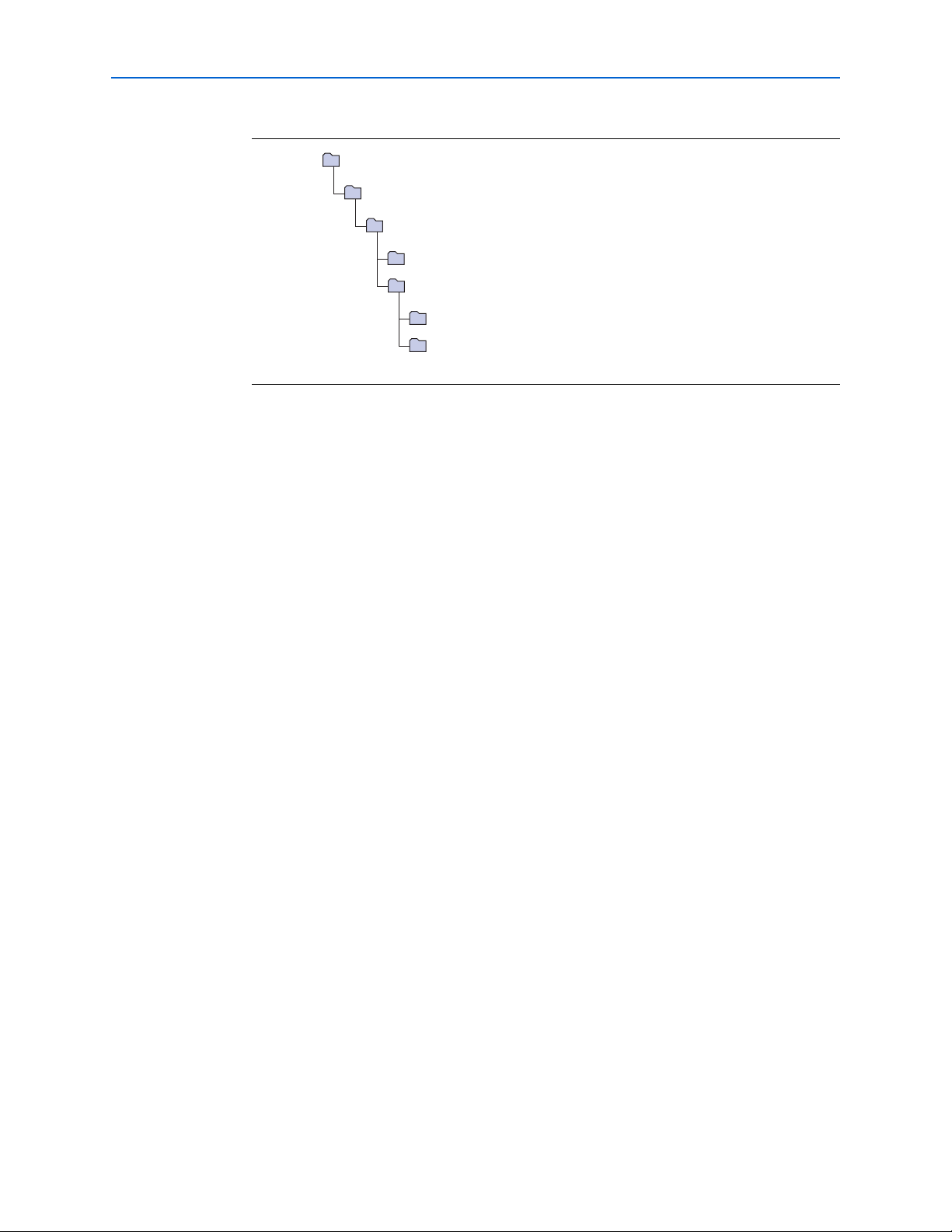
Figure 1–1 shows the directory structure after you install the CRC Compiler User
Guide Compiler, where <path> is the installation directory. The default installation
directory on Windows is c:\altera\<version>; on UNIX and Solaris it is
/opt/altera/<version>.
CRC Compiler User Guide © November 2009 Altera Corporation
®
II software and downloadable from the Altera® website, www.altera.com.
Preliminary
Page 9
Chapter 1: About This Compiler 1–5
ip
Contains the MegaCore IP Library.
common
Contains the shared components.
crc_compiler
Contains the CRC Compiler files and documentation.
doc
Contains all the documentation for the CRC Compiler.
lib
Contains encrypted lower level design files and other support files.
<path>
Installation directory.
altera
Contains all MegaCore IP Library from Altera.
Installation and Licensing
Figure 1–1. Directory Structure
OpenCore Plus Evaluation
With Altera’s free OpenCore Plus evaluation feature, you can perform the following
actions:
■ Simulate the behavior of a megafunction (Altera MegaCore function or AMPP
megafunction) within your system.
SM
OpenCore Plus Time-Out Behavior
© November 2009 Altera Corporation CRC Compiler User Guide
■ Verify the functionality of your design, as well as evaluate its size and speed
quickly and easily.
■ Generate time-limited device programming files for designs that include
megafunctions.
■ Program a device and verify your design in hardware.
You only need to purchase a license for the megafunction when you are completely
satisfied with its functionality and performance, and want to take your design to
production.
After you purchase a license for CRC Compiler MegaCore function, you can request a
license file from the Altera website at www.altera.com/licensing and install it on your
computer. When you request a license file, Altera emails you a license.dat file. If you
do not have Internet access, contact your local Altera representative.
f For more information on OpenCore Plus hardware evaluation, refer to AN 320:
OpenCore Plus Evaluation of Megafunctions.
OpenCoree Plus hardware evaluation supports the following two operation modes:
■ Untethered—the design runs for a limited time.
■ Tethered—requires a connection between your board and the host computer. If
tethered mode is supported by all megafunctions in a design, the device can
operate for a longer time or indefinitely.
Preliminary
Page 10

1–6 Chapter 1: About This Compiler
Installation and Licensing
All megafunctions in a device time out simultaneously when the most restrictive
evaluation time is reached. If there is more than one megafunction in a design, a
specific megafunction’s time-out behavior may be masked by the time-out behavior of
the other megafunctions.
1 For MegaCore functions, the untethered timeout is 1 hour; the tethered timeout value
is indefinite.
Your design stops working after the evaluation time expires; the checksum output
signal in a generator and the crcbad output signal in a checker are forced low.
CRC Compiler User Guide © November 2009 Altera Corporation
Preliminary
Page 11

Design Flow
f For more information on IP functional simulation models, refer to the Simulating
2. Getting Started
To evaluate the CRC compiler using the OpenCore Plus feature include these steps in
your design flow:
1. Obtain and install the CRC compiler.
2. Create a custom variation of the CRC compiler.
3. Implement the rest of your design using the design entry method of your choice.
4. Use the IP functional simulation model to verify the operation of your design.
Altera IP in Third-Party Simulation Tools chapter in volume 3 of the Quartus II
Handbook.
5. Use the Quartus II software to compile your design.
1 You also can generate an OpenCore Plus time-limited programming file,
which you can use to verify the operation of your design in hardware.
6. Purchase a license for the CRC compiler.
After you have purchased a license for the CRC compiler, follow these additional
steps:
1. Set up licensing.
2. Generate a programming file for the Altera
3. Program the Altera device(s) with the completed design.
CRC Compiler Walkthrough
This walkthrough explains how to create a CRC compiler MegaCore function
variation using the Quartus II MegaWizard
generating your custom variation, you can incorporate it into your overall project.
This walkthrough requires the following steps:
■ Create a New Quartus II Project
■ Launch the MegaWizard Plug-In Manager
■ Parameterize
®
device(s) on your board.
™
Plug-In Manager. When you finish
■ Set Up Simulation
■ Generate Files
© November 2009 Altera Corporation CRC Compiler User Guide
Preliminary
Page 12

2–2 Chapter 2: Getting Started
CRC Compiler Walkthrough
Create a New Quartus II Project
You need to create a new Quartus II project with the New Project Wizard, which
specifies the working directory for the project, assigns the project name, and
designates the name of the top-level design entity.
To create a new project, follow these steps:
1. Choose Programs > Altera > Quartus II <version> (Windows Start menu) to run
the Quartus II software. Alternatively, you can use the Quartus II Web Edition
software.
2. Choose New Project Wizard (File menu).
3. Click Next in the New Project Wizard Introduction page (the introduction page
does not display if you turned it off previously).
4. In the New Project Wizard: Directory, Name, Top-Level Entity page, enter the
following information:
a. Specify the working directory for your project. For example, this walkthrough
uses the c:\altera\projects\crc_project directory.
b. Specify the name of the project. This walkthrough uses example for the project
name.
1 The Quartus II software automatically specifies a top-level design entity
that has the same name as the project. This walkthrough assumes the names
are the same.
5. Click Next to close this page and display the New Project Wizard: Add Files page.
1 When you specify a directory that does not already exist, a message asks
you if the specified directory should be created. Click Yes to create the
directory.
6. If you installed the MegaCore IP Library in a different directory from where you
installed Quartus II, you must add the user libraries:
a. Click User Libraries.
b. Type <path>\ip\altera in the Library name box, where <path> is the
directory in which you installed the CRC compiler.
c. Click Add to add the path to the Quartus II project.
d. Click OK to save the library path in the project.
7. Click Next to close this page and display the New Project Wizard: Family &
Device Settings page.
8. On the New Project Wizard: Family & Device Settings page, choose the target
device family in the Family list.
9. The remaining pages in the New Project Wizard are optional. Click Finish to
complete the Quartus II project setup.
You have finished creating your new Quartus II project.
CRC Compiler User Guide © November 2009 Altera Corporation
Preliminary
Page 13

Chapter 2: Getting Started 2–3
CRC Compiler Walkthrough
Launch the MegaWizard Plug-In Manager
To launch the MegaWizard Plug-In Manager in the Quartus II software, follow these
steps:
1. Start the MegaWizard Plug-In Manager by choosing MegaWizard Plug-In
Manager (Tools menu). The MegaWizard Plug-In Manager dialog box displays .
f Refer to Quartus II Help for more information on how to use the
MegaWizard Plug-In Manager.
2. Ensure Create a new custom megafunction variation is selected and click Next.
3. Expand the folder under Installed Plug-Ins by clicking the + icon next to
Communications. Expand the Additional Functions directory and select CRC
Compiler v9.1.
4. Choose the device family that you want to use for this MegaCore function
variation; for this example, select Stratix II GX.
5. Select the output file type for your design; the CRC compiler supports VHDL and
Ver il og HD L.
1 You can change the page displayed in the MegaWizard Plug-In Manager by clicking
Parameterize
6. The MegaWizard Plug-In Manager shows the project path that you specified in the
New Project Wizard. Append a variation name for the MegaCore function output
files <project path>\<variation name>.
7. Click Next to display the Parameter Settings page for the CRC compiler.
Next or Back at the bottom of the dialog box. You can also move directly to a named
page by clicking Parameter Settings, EDA, or Summary.
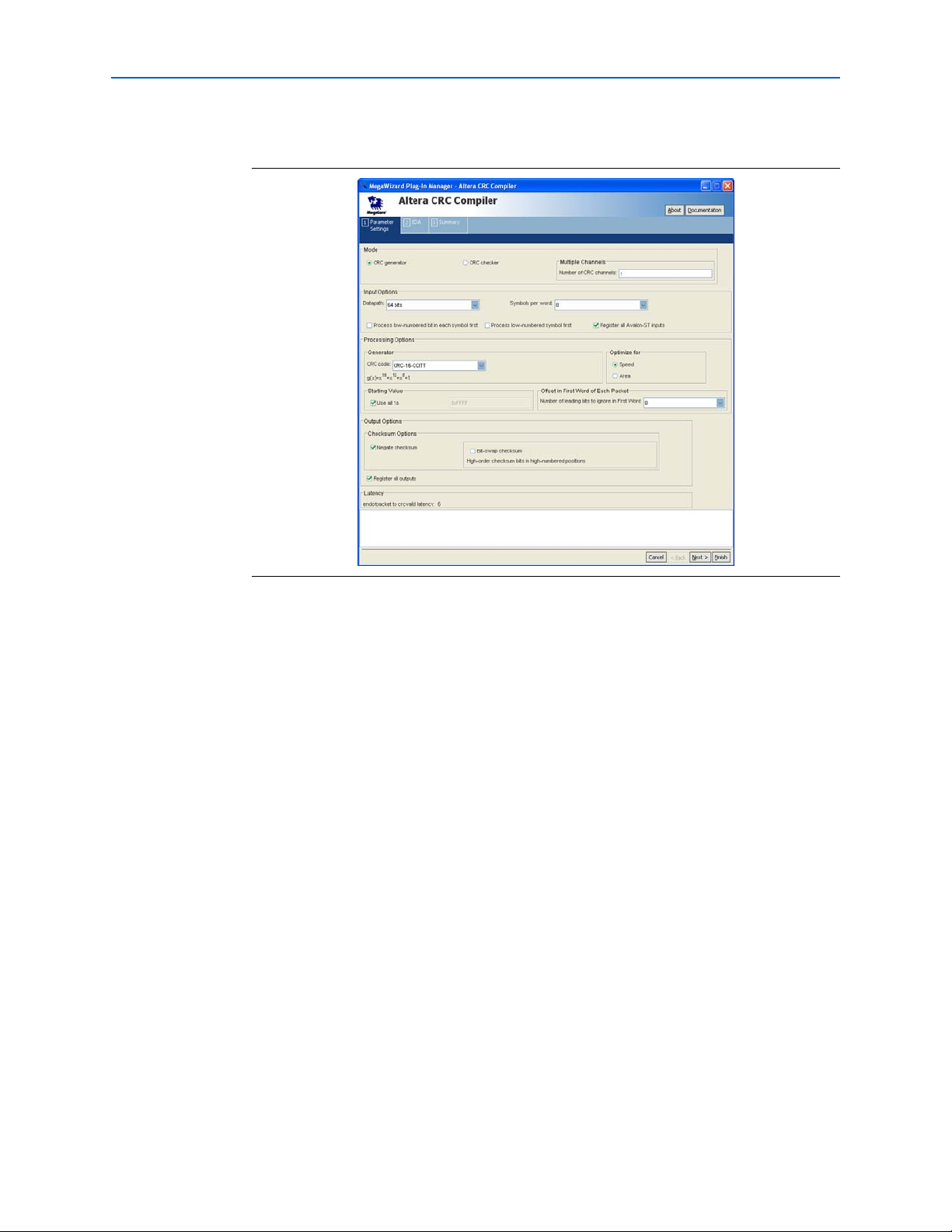
To parameterize your CRC compiler MegaCore function, specify the following values
on the Parameter Settings page:
■ For Mode, ensure that CRC generator is selected.
■ For Input Options, specify these values:
■ Datapath, specify 64 bits.
■ Symbols per word, specify 8.
■ For Processing Options, specify these options:
■ Generator, CRC Code, specify CRC-16-CCITT.
■ Optimize for, select Speed.
■ For the rest of the options, use the default values.
© November 2009 Altera Corporation CRC Compiler User Guide
Preliminary
Page 14
2–4 Chapter 2: Getting Started
CRC Compiler Walkthrough
Figure 2–1 shows you the Parameter Settings page.
Figure 2–1. Parameters Setting Page
Set Up Simulation
c You may only use these models for simulation and expressly not for synthesis or any
To generate a simulation model or a netlist, click Next (or the EDA tab) to display the
EDA page. Turn on the options as required.
An IP functional simulation model is a cycle-accurate VHDL or Verilog HDL model
produced by the Quartus II software. The model allows for fast functional simulation
of IP using industry-standard VHDL and Verilog HDL simulators.
other purposes. Using these models for synthesis creates a nonfunctional design.
To generate an IP functional simulation model for your MegaCore function, follow
these steps:
1. Turn on Generate Simulation Model.
1 Some third-party synthesis tools can use a netlist that contains only the
structure of the MegaCore function, but not detailed logic, to optimize
performance of the design that contains the MegaCore function. Turn on
Generate netlist only if your synthesis tool supports this feature.
2. Click Next (or the Summary tab) to display the Summary page.
You can use the check boxes on the Summary page to enable or disable the generation
of specified files. A gray checkmark indicates a file that is automatically generated;
other files are optional.
CRC Compiler User Guide © November 2009 Altera Corporation
Preliminary
Page 15

Chapter 2: Getting Started 2–5
CRC Compiler Walkthrough
You can click Back to display the previous page or click Parameter Setting, EDA or
Summary, if you want to change any of the MegaWizard options.
Generate Files
To generate the files, follow these steps:
1. Turn on the files you wish to generate.
1 At this stage you can still click Back or the pages to display any of the other
pages in the MegaWizard interface, if you want to change any of the
parameters.
2. To generate the specified files and close the MegaWizard interface, click Finish.
The Generation Status Window appears. After file generation is successful, click
Exit to close the window.
1 The generation phase may take several minutes to complete. The
generation status window tells you the files that are generated and reports
whether the generation phase was successful or not.
3. After you review the generation report, click Exit to close the MegaWizard Plug-In
Manager and click Yes on the Quartus II IP Files message.
1 The Quartus II IP File (.qip) is a file generated by the MegaWizard interface
or SOPC Builder that contains information about a generated IP core. You
are prompted to add this .qip file to the current Quartus II project at the
time of file generation. In most cases, the .qip file contains all of the
necessary assignments and information required to process the core or
system in the Quartus II compiler. Generally, a single .qip file is generated
for each MegaCore function and for each SOPC Builder system. However,
some more complex SOPC Builder components generate a separate .qip
file, so the system .qip file references the component .qip file.
Tab le 2– 1 describes the generated files and other files that may be in your project
directory. The names and types of files specified in the summary vary based on
whether you created your design with VHDL or Verilog HDL.
Table 2–1. Generated Files (Sheet 1 of 2)
File Name Description
<variation name>.bsf Quartus II symbol file for the MegaCore function variation.
You can use this file in the Quartus II block diagram editor.
<variation name>.cmp A VHDL component declaration file for the MegaCore
function variation. Add the contents of this file to any VHDL
architecture that instantiates the MegaCore function.
<variation name>.html Report file which contains lists of the generated files and
ports for the MegaCore function variation.
<variation name>.vo or .vho VHDL or Verilog HDL IP functional simulation model.
© November 2009 Altera Corporation CRC Compiler User Guide
Preliminary
Page 16

2–6 Chapter 2: Getting Started
Table 2–1. Generated Files (Sheet 2 of 2)
File Name Description
<variation name>.vhd or .v A MegaCore function variation file, which defines a VHDL
or Verilog HDL top-level description of the custom
MegaCore function. Instantiate the entity defined by this
file inside of your design. Include this file when compiling
your design in the Quartus II software.
<variation name>_bb.v Verilog HDL black-box file for the MegaCore function
variation. Use this file when using a third-party EDA tool to
synthesize your design.
<variation name>.qip Contains Quartus II project information for your MegaCore
function variations.
<variation name>_syn.v A timing and resource estimation netlist for use in some
third-party synthesis tools. This file is generated when the
option Generate netlist on the EDA page is turned on.
testbench/tb.v(hd) or
testbench/tb_multichan.v(hd)
testbench/crcdemo.v(hd) or
testbench/crcdemo_multichan.v(hd)
testbench/crcgen.v(hd) or
testbench/crcgen_multichan.v(hd)
testbench/crcchk.v(hd) or
testbench/crcchk_multichan.v(hd)
A Verilog or VHDL testbench file that provides a testbench
for the CRC compiler MegaCore function variation.
A Verilog or VHDL example design incorporating a CRC
generator, checker, and other supporting models.
Wrapper for example variations of the CRC Compiler
MegaCore function used in the testbench.
Wrapper for example variations of the CRC Compiler
MegaCore function used in the testbench.
Simulate the Design
You can now integrate your custom MegaCore function variation into your design,
simulate, and compile your design.
Simulate the Design
You can simulate your design using the MegaWizard-generated VHDL or Verilog
HDL IP functional simulation models. These simulation models are generated in the
language you selected in “Set Up Simulation” on page 2–4.
For an example of simulating a design, refer to the section, “Running the Testbench
Example” on page 3–8.
f For more information on IP functional simulation models, refer to the Simulating
Altera IP in Third-Party Simulation Tools chapter in volume 3 of the Quartus II
Handbook.
Compile the Design
You can use the Quartus II software to compile your design. Refer to Quartus II Help
for instructions on compiling your design.
Program a Device
After you compile your design, program your targeted Altera device and verify your
design in hardware.
CRC Compiler User Guide © November 2009 Altera Corporation
Preliminary
Page 17

Functional Overview
clk
reset_n
data
crcchannel
(1)
datavalid
startofpacket
endofpacket
checksum
datachannel
(1)
chaninitdone
(1)
CRC GENERATOR
empty
crcvalid
The CRC Compiler MegaCore function generates high-performance circuits to
generate or check Cyclic Redundancy Check checksums for packet-based
communication. The CRC Compiler dynamically generates RTL based on
requirements you supply, rather than parameterizing static RTL.
The generated CRC MegaCore function uses an Avalon-ST interface to receive data.
Generated checksums for transmission or the status of received checksums are
emitted on dedicated ports. The CRC MegaCore function does not provide an
Av al on
®
interface. The generated CRC MegaCore function also does not store any data,
checksums, or status.
CRC Generator
3. Functional Description
Memory-Mapped (Avalon-MM) interface or any other software access
Figure 3–1 shows the block diagram of the CRC generator.
Figure 3–1. CRC Generator Block Diagram
Note to Figure 3–1:
(1) These signals are present only in a multi-channel generator.
The CRC Generator receives message bits from the data input interface on each clock
cycle during which datavalid is asserted. The datavalid signal may be asserted
or deasserted arbitrarily during or between packets. When datavalid is asserted,
all data pins must contain valid data and the empty signal must be zero, with the
exception of the final word of a packet. The empty signal, if used, must be set to zero
during all cycles except the last word of a packet, that is when endofpacket is
asserted. If datavalid is deasserted, data, startofpacket, endofpacket, and
© November 2009 Altera Corporation CRC Compiler User Guide
Preliminary
Page 18

3–2 Chapter 3: Functional Description
Data source
CRC
Generator
Merge
Message bits
Codeword
bits
Transmitter
CRC Generator
empty are ignored. Following a fixed number of clock cycles after the final word,
indicated by assertion of endofpacket, crcvalid is asserted and the computed
CRC value is available on the checksum output. The value of checksum is
undefined at other times. For the delay between assertion of endofpacket and
crcvalid, refer to the Latency panel of the MegaWizard interface.
The CRC generator can start computing the checksum of a new packet while it is
completing the calculation for the previous packet, that is before it asserts crcvalid.
The data source may assert startofpacket on the clock cycle immediately
following endofpacket, regardless of the generator's latency.
Figure 3–2 and Figure 3–3 shows a typical application of the CRC Generator and
operations respectively.
Figure 3–2. Typical CRC Generator Application
Figure 3–3. CRC Generator Operation
clk
startofpacket
endofpacket
empty[3:0]
datavalid
data[7:0]
crcvalid
checksum[7:0]
data1 data2 data3 data4 data5 data6 data1 data2 data3 data4 data5
0
checksum
CRC Compiler User Guide © November 2009 Altera Corporation
Preliminary
Page 19

Chapter 3: Functional Description 3–3
Receiver
CRC
Checker
Codeword bits
Data sink
crcbad
CRC Checker
CRC Checker
Figure 3–4 shows the block diagram for the CRC Checker.
Figure 3–4. CRC Checker Block Diagram
CRC CHECKER
clk
reset_n
data
datavalid
startofpacket
endofpacket
empty
datachannel
Note to Figure 3–4:
(1) These signals are present only in a multi-channel checker.
(1)
crcbad
crcvalid
chaninitdone
crcchannel
(1)
(1)
The CRC Compiler MegaCore function receives message and checksum (codeword)
bits from the data input interface on each clock cycle during which datavalid is
asserted. The datavalid signal can be asserted or deasserted arbitrarily during or
between packets as shown in Figure 3–5 on page 3–3 and Figure 3–6 on page 3–4.
When datavalid is asserted, all data pins must contain valid data and the empty
signal must be zero, with the exception of the final word of a packet. The empty
signal, if used, must be set to 0 during all cycles except the last word of a packet, that
is when endofpacket is asserted. If datavalid is deasserted, data,
startofpacket, endofpacket, and empty are ignored. Following a fixed number
of clock cycles after the final word, indicated by assertion of endofpacket,
crcvalid is asserted and the crcbad output is set to 1 if the calculated syndrome is
incorrect. The value of crcbad is undefined at other times. For the delay between
assertion of endofpacket and crcvalid, refer to the Latency panel of the
MegaWizard interface.
The CRC checker can start computing the checksum of a new packet while it is
completing the calculation for the previous packet, that is before it asserts crcvalid.
The data source may assert startofpacket on the clock cycle immediately
following endofpacket, regardless of the checker's latency.
Figure 3–5. Typical CRC Checker Application
© November 2009 Altera Corporation CRC Compiler User Guide
Preliminary
Page 20

3–4 Chapter 3: Functional Description
clk
startofpacket
endofpacket
empty[3:0]
datavalid
data[7:0]
crcvalid
crcbad
0 0 n
data1 data2 data3 data4 data5
checksum
clk
startofpacket
endofpacket
empty[3:0]
datavalid
data[7:0]
crcvalid
crcbad
0 n 0
data1 data2 data3 data4 data5 data6
checksum
data1
Multi-Channel Operation
Figure 3–6. Checker Operation With Good Codeword
Figure 3–7. Checker Operation With Bad Codeword
Multi-Channel Operation
For multi-channel (Number of CRC Channels > 1) operations, the CRC Compiler
inserts context memories which allow a generator or checker to process multiple
packets concurrently. Both speed and area optimization variants support multichannel operation.
On each datavalid cycle, user applications must set the datachannel input signal
to the channel context in use. The MegaCore function sets the crcchannel output
signal to the same value after a fixed number of clock latency (at the assertion of
crcvalid), to indicate the channel the crcbad or checksum output signal applies
to.
There is no channel switch latency or minimum number of cycles between context
switches, and no restriction on channel ordering is imposed. The latency of a multichannel MegaCore function is identical to that of the corresponding single-channel
MegaCore function.
However, there is an fmax penalty in multi-channel operation. After each system reset
CRC Compiler User Guide © November 2009 Altera Corporation
(reset_n = 0), there will be a slight delay in terms of the number of clock cycles due
to an internal initialization of the context to a known state. The chaninitdone
output signal is asserted when the internal initialization is done. You must wait until
this output signal is asserted before sending any data to the MegaCore function for
processing.
Preliminary
Page 21

Chapter 3: Functional Description 3–5
Multi-Channel Operation
Figure 3–8 shows the operation of a multi-channel generator.
Figure 3–8. Multi-Channel Generator Operation
clk
datachannel
010
101
000
chaninitdone
startofpacket
endofpacket
data
data1 data2 data4 data1 data3 data4
data3 data2 data1 data2
datavalid
crcchannel
010
crcvalid
checksum
checksum
Figure 3–9 and Figure 3–10 show the operation of a multi-channel checker when
processing a good and incorrect codeword, respectively.
Figure 3–9. Multi-Channel Checker Operation with Good Codeword
clk
datachannel
010
datavalid
startofpacket
endofpacket
data
data1 data2 data1 checksum data1checksum data2 data2 checksum
chaninitdone
crcchannel
crcvalid
crcbad
Figure 3–10. Multi-Channel Checker Operation with Incorrect Codeword
clk
datachannel
datavalid
startofpacket
endofpacket
data
chaninitdone
010
data1 data2 data1 checksum data1checksum data2 data2 checksum
010
101
101
000
101
000
crcchannel
010
101
crcvalid
crcbad
© November 2009 Altera Corporation CRC Compiler User Guide
Preliminary
Page 22

3–6 Chapter 3: Functional Description
Parameters
Parameters
You specify the parameters for the CRC Compiler MegaCore functions using the
MegaWizard interface. Tab le 3– 1 describes each available parameter.
Table 3–1. MegaWizard Control Settings
Parameter Description
CRC Generator Creates a generator MegaCore function
CRC Checker Creates a checker MegaCore function
Number of CRC Channels Specifies the number of CRCs supported. All input and output signals are shared
among the channels. Hence, only 1 channel can be processed at any one time.
Datapath Selects the width of the data input
Symbols per word Specifies the number of symbols in a datapath, and thus defines the width of each
symbol in bits. A symbol represents the smallest unit of data in a word. For
example, if Datapath is set to 32 bits and Symbols per word is set to 4, the width of
each symbol is 8 bits.
Process low-numbered bit in each
symbol first
Process low-numbered symbol first Processes the symbols in reverse order. For example, given the Datapath is 12 bits
Register all Avalon-ST inputs Buffers data, datavalid, startofpacket, endofpacket, and empty
Optimize for: speed Inserts logic to increase the maximum clock speed
Optimize for: area Removes logic to reduce logic utilization and latency
CRC Code Selects the generator polynomial by name
Starting value Presets the CRC register to this value before each packet.
Number of leading bits to ignore in
First word
Negate checksum Sets checksum to the one’s complement of the result of the polynomial division.
Bit-swap checksum Applies only to CRC Generator. Selecting this parameter reverses the sequence of
Register all outputs Buffers crcvalid and checksum, or crcbad with flip-flops.
Processes each symbol in reverse order. For example, given the Datapath is 12 bits
and Symbols per word is 3, turning on this parameter causes the MegaCore
function to process “abcd efgh ijkl” as “dcba hgfe lkji”.
and Symbols per word is 3, turning on this parameter causes the MegaCore
function to process “abcd efgh ijkl” as “ijkl efgh abcd”.
If both parameters, Process low-numbered bit in each symbol first and Process
low-numbered symbol first are turned on, the MegaCore processes the entire data
in reverse order.
signals with flip-flops
Specifies the number of bits to ignore at the beginning of a packet.
Not applicable to the CRC checker.
the entire output bits. The low-order bits of the remainder are placed in the highorder bits of the checksum. Select this parameter if data transmission starts from
low-order bit.
CRC Compiler User Guide © November 2009 Altera Corporation
Preliminary
Page 23

Chapter 3: Functional Description 3–7
Signals
Signals
Tab le 3– 2 describes the I/O signals of a CRC MegaCore function.
Table 3–2. CRC Signals
Signal Direction Description
clk In System clock.
reset_n In Asynchronous reset signal, which is active at 0.
data[(n-1):0] In Message bits for generator; codeword bits for checker, where n is a power of 2,
from 1 through 256, (1, 2, 4, 8,16, 32, 64,128, or 256).
datavalid In Asserted by the source to indicate new packet data.
startofpacket In Asserted by the source to mark the beginning of a packet. This signal is present
only when the parameter Optimize for: speed is set to ON or Number of leading
bits to ignore in First word is greater than 0.
endofpacket In Asserted by the source to mark the end of a packet.
empty[(n-1):0] In The number of empty symbols during cycles that contain the end of a packet.
This signal must be set to 0 during other cycles when datavalid is
asserted. The value of n equals log
is present only when the parameter Symbols per word is greater than 1.
checksum[(n-1):0] Out Computed CRC output, where n equals the order of the generator polynomial.
This signal is present only in CRC generator.
crcbad Out Asserted if the previous packet had an incorrect CRC. This signal is present only
in CRC checker.
crcvalid Out Asserted when the core has completed calculation of the checksum or
crcbad value.
Multi-Channel Signals
datachannel[(n-1):0] In The channel on which data is received by the generator or checker. The value of
n equals log
(number of CRC channels).
2
chaninitdone Out Asserted when the MegaCore function has completed its internal initialization
process and ready to receive data for processing. User applications must wait
for chaninitdone to be asserted before sending data to the MegaCore
function for processing. The MegaCore function reinitializes itself each time the
reset_n signal is asserted.
crcchannel[(n-1):0] Out Indicates the channel whose result is presented at the checksum (generator)
or crcbad (checker) output signal. The value of n equals log
channels).
(number of symbols per word). This signal
2
(number of CRC
2
Testbench
The testbench shows you a typical variant created by the CRC Compiler. The variant
and the testbench are fixed and may differ from the variant you create.
The testbench is available in both Verilog and VHDL, plaintext except for the CRC IP
Functional Simulation models. The testbench models are synthesizable RTL which
allows you to compile and to run the testbench in hardware. The architecture is
shown in Figure 3–11.
© November 2009 Altera Corporation CRC Compiler User Guide
Preliminary
Page 24

3–8 Chapter 3: Functional Description
Dat a generat or
CRC
Generator
Merge Channel
CRC checker
Error
status
Codeword
Codeword
+ errors
Message
word
Running the Testbench Example
Figure 3–11. Testbench Architecture
The packet generator module creates sample message words (packets without CRCs).
The CRC generator creates a checksum, which the merge module appends to the end
of the packet. The merge module delays the data to account for generator processing
time. The result is a codeword. The channel module inserts errors in the codewords,
as indicated by the errorInserted signal. The CRC checker indicates the presence
of errors in the received codewords. The testbench shows detected errors using the
errorDetected signal.
Running the Testbench Example
In this section you run the testbench example to illustrate how you do the following
tasks:
■ Create a testbench project using the Quartus II New Project Wizard
■ Create simulation models for the generator and checker using the MegaWizard
interface
■ Set EDA Tool Settings to simulate your testbench project
■ Run compilation and analysis
When you create a MegaCore function variation and turn on the Generate
Simulation Model option on the EDA page, the Quartus II software generates the
simulation model in the project directory. The simulation model is an Intellectual
Property Functional Simulation (IPFS) model with a file extension of .vo or .vho,
depending on the language you select. It also creates an example design in the
testbench subdirectory. The testbench subdirectory contains the data generator,
merge, and channel modules for the example testbench in the following files:
■ A top-level simulation file, tb.v or tb.vhd.
■ crcdemo.v(hd) for a single channel MegaCore function or
crcdemo_multichan.v(hd) for a multichannel MegaCore function
■ A generator variation file, crcgen.v(hd) for a single channel MegaCore function or
crcgen_multichan.v(hd) for a multichannel MegaCore function.
■ The corresponding checker variation file, crcchk.v(hd) for a single channel
MegaCore or crcchk_multichan.v(hd) for a multichannel MegaCore.
CRC Compiler User Guide © November 2009 Altera Corporation
Preliminary
Page 25

Chapter 3: Functional Description 3–9
Running the Testbench Example
The CRC demonstration testbench is supported by the following simulators:
Ve r il o g : Mentor ModelSim SE and AE, Cadence NCSim, Synopsys VCS and VCSMX
VHDL: Mentor ModelSim SE and AE, Cadence NCSim, and Synopsys VCS-MX.
For up-to-date information on the supported versions of these simulators, reference
the Altera website: www.altera.com.
Create a New Project for the Testbench
Following the steps below, create a Quartus II project in the testbench directory.
1. Choose New Project Wizard (File menu).
2. Click Next in the New Project Wizard Introduction page (the introduction page
does not display if you turned it off previously).
3. In the New Project Wizard: Directory, Name, Top-Level Entity page, enter the
following information:
a. Specify the working directory for your testbench project, which should be the
testbench directory created in your previous project directory. For example,
this walkthrough uses the directory c:\altera\projects\crc_project\testbench.
b. Specify crcdemo for the name of the project.
The Quartus II software automatically specifies a top-level design entity that
has the same name as the project. This walkthrough assumes the names are the
same.
c. If the directory already exists, a dialog displays that asks what action to take.
Click the Delete the existing project and continue using the New Project
Wizard and then click OK to continue.
4. The New Project Wizard: Add Files page displays.
a. Select the file crcdemo.v or crcdemo.vhd, depending on the language in which
your MegaCore function was created, and click Add to add the file to your
project.
b. Click Finish to add the file to your project.
Create the Generator and Checker Files
In this section, you create the generator and checker variation files.
1. Open the MegaWizard Plug-In Manager and click Edit an existing custom
megafunction variation to edit the CRC generator wrapper file crcgen.v or
crcgen.vhd
2. Click Next to display the page from which you select the generator wrapper file,
crcgen.v or crcgen.vhd, in the testbench directory.
3. After you select the crcgen.v or crcgen.vhd the file, click Next to continue.
1 You can review the parameters, but it is recommended that you don’t
change the settings.
© November 2009 Altera Corporation CRC Compiler User Guide
Preliminary
Page 26

3–10 Chapter 3: Functional Description
Running the Testbench Example
4. Click the Simulation tab and ensure that Generate Simulation Model is checked.
Click Finish to create the IPFS model for the CRC generator.
5. The generation window displays the files being generated and the generation
status. After the files are generated successfully, click Exit.
Create a Simulation Model for the Checker
1. Open the MegaWizard Plug-In Manager again (see Step 1 in the previous
section“Create the Generator and Checker Files” on page 3–9) to edit the CRC
checker wrapper file crcchk.v or crcchk.vhd, in the testbench directory.
2. Click Next to display the page from which you select the CRC checker wrapper
file, crcchk.v or crcchk.vhd.
3. After you select the crcchk.v or crcchk.vhd the file, click Next to continue.
1 You can review the parameters, but it is recommended that you don’t
change the settings.
4. Click the Simulation tab and ensure that Generate Simulation Model is checked.
5. Click Finish to create the IPFS model for the CRC checker.
Compile and Simulate the Testbench
In this section, you navigate the Quartus II software interface to compile and simulate
the testbench.
1. Using the Quartus II software, open the Assignments/EDA Tool Settings... menu,
then click the plus sign (+) to expand the EDA Tool Settings category and select
Simulation to display the Quartus II Simulation page.
2. Set the Tool Name to the simulator of your choice. In this example, it is ModelSim-
Altera.
3. Click Compile test bench: in the NativeLink settings, then click Test Benches...
4. In the Test Benches page, click New...
5. In the New Test Bench Settings page, set Test bench name:, Test bench entity:, and
Instance: all to tb. Set Run for: to 100 us. In the Test bench files, set File name: to
tb.v or tb.vhd and then click Add.
6. Click OK to apply these settings. The Test Benches page displays the settings.
7. You can review the testbench settings. If these setting are correct, click OK to
confirm this is the testbench file and settings that you want to use.
8. Click OK to close the EDA Tools ->Simulation page.
9. Open the Tools->Options menu and select EDA Tool Options.
10. Double-click the simulator you chose in Step 1 and enter the path to the
executable. Click OK to close the EDA Tool Options page.
11. In the Quartus II Processing menu, select Start->Start Analysis & Elaboration.
After the testbench compiles successfully, a message displays telling you that the
compilation was successful and informs you of the number of warnings that exist.
CRC Compiler User Guide © November 2009 Altera Corporation
Preliminary
Page 27

Chapter 3: Functional Description 3–11
Running the Testbench Example
12. Click OK to close the compilation message.
13. In the Quartus II Tools menu, select EDA Simulation Tool->Run EDA RTL
Simulation.
14. The Quartus II software starts the simulator you chose in interactive mode and
simulates the design. Consult the vendor's documentation for information on how
to use the simulator. When you have finished using the simulator, quit the
simulator and continue using Quartus II software.
© November 2009 Altera Corporation CRC Compiler User Guide
Preliminary
Page 28

3–12 Chapter 3: Functional Description
Running the Testbench Example
CRC Compiler User Guide © November 2009 Altera Corporation
Preliminary
Page 29

Revision History
The following table shows the revision history for this user guide.
Date Version Changes Made
October 2013 13.0 Added obsolescence notice. Refer to PDN1304.
November 2009 9.1 Maintenance release.
March 2009 9.0
November 2008 8.1 Maintenance release.
May 2008 8.0
October 2007 7.2
May 2007 7.1
December 2006 7.0
December 2006 6.1 New user guide for CRC Compiler version 6.1.
■ Added support for Arria II GX device family.
■ Removed support for HardCopy Stratix device family
■ Maintenance release.
■ Added support for Stratix IV device family.
■ Maintenance release; updated version numbers.
■ Added information for multi-channel operation.
■ Added block diagrams of the MegaCore functions.
■ Added description of new signals and parameters.
■ Added support for Arria GX device family.
■ Revised descriptions for parameters: Symbols per word, Process low-numbered bits first
and Bit-swap checksum.
■ Added new sections: Bit Order Reversal in a Symbol and Partial Word.
■ Added support for Cyclone III device family.
■ Maintenance release; updated version numbers.
Additional Information
How to Contact Altera
For the most up-to-date information about Altera® products, see the following table.
Contact
Contact (Note 1)
Technical support Website www.altera.com/support
Technical training Website www.altera.com/training
Altera literature services Email literature@altera.com
Non-technical support (General) Email nacomp@altera.com
(Software Licensing) Email authorization@altera.com
Note:
(1) You can also contact your local Altera sales office or sales representative.
© November 2009 Altera Corporation CRC Compiler User Guide
Preliminary
Method Address
Email custrain@altera.com
Page 30

Info–ii
Typographic Conventions
Typographic Conventions
The following table shows the typographic conventions that this document uses.
Visual Cue Meaning
Bold Type with Initial Capital
Letters
bold type Indicates directory names, project names, disk drive names, file names, file name
Italic Type with Initial Capital Letters Indicates document titles. For example, AN 519: Stratix IV Design Guidelines.
Italic type Indicates variables. For example, n + 1.
Initial Capital Letters Indicates keyboard keys and menu names. For example, Delete key and the Options
“Subheading Title” Quotation marks indicate references to sections within a document and titles of
Courier type Indicates signal, port, register, bit, block, and primitive names. For example, data1,
1., 2., 3., and
a., b., c., and so on.
■ ■ Bullets indicate a list of items when the sequence of the items is not important.
1 The hand points to information that requires special attention.
c
w
r The angled arrow instructs you to press Enter.
f The feet direct you to more information about a particular topic.
Indicates command names, dialog box titles, dialog box options, and other GUI
labels. For example, Save As dialog box.
extensions, and software utility names. For example, \qdesigns directory, d: drive,
and chiptrip.gdf file.
Variable names are enclosed in angle brackets (< >). For example, <file name> and
<project name>.pof file.
menu.
Quartus II Help topics. For example, “Typographic Conventions.”
tdi, and input. Active-low signals are denoted by suffix n. For example,
resetn.
Indicates command line commands and anything that must be typed exactly as it
appears. For example, c:\qdesigns\tutorial\chiptrip.gdf.
Also indicates sections of an actual file, such as a Report File, references to parts of
files (for example, the AHDL keyword SUBDESIGN), and logic function names (for
example, TRI).
Numbered steps indicate a list of items when the sequence of the items is important,
such as the steps listed in a procedure.
A caution calls attention to a condition or possible situation that can damage or
destroy the product or your work.
A warning calls attention to a condition or possible situation that can cause you
injury.
CRC Compiler User Guide © November 2009 Altera Corporation
Preliminary
 Loading...