

Page 1

Introduction to Avalon Verification IP Suite
User Guide
Subscribe
Send Feedback
UG-01073
2014.06.30
101 Innovation Drive
San Jose, CA 95134
www.altera.com
Page 2

TOC-2
Introduction to Avalon Verification IP SuiteUser Guide
Contents
Introduction to Avalon Verification IP Suite ....................................................1-1
Clock Source BFM ..............................................................................................2-1
Advantages of Using BFMs and Monitors ..............................................................................................1-1
BFM Implementation .................................................................................................................................1-1
Application Programming Interface ........................................................................................................1-3
Application Example of BFMs ..................................................................................................................1-3
Parameters ....................................................................................................................................................2-1
Clock Source API.........................................................................................................................................2-1
Clock_stop() ....................................................................................................................................2-2
get_run_state() ................................................................................................................................2-2
get_version() ....................................................................................................................................2-2
Reset Source BFM ...............................................................................................3-1
Parameters ....................................................................................................................................................3-1
Reset Source API..........................................................................................................................................3-1
reset_deassert ...................................................................................................................................3-2
get_version() ....................................................................................................................................3-2
Avalon Interrupt Source and Interrupt Sink BFMs ..........................................4-1
Parameters ....................................................................................................................................................4-1
Interrupt Source and Sink API...................................................................................................................4-2
get_irq() ............................................................................................................................................4-2
get_version() ....................................................................................................................................4-2
set_irq() ............................................................................................................................................4-3
Avalon-MM Master BFM ...................................................................................5-1
Timing ..........................................................................................................................................................5-2
Block Diagram .............................................................................................................................................5-5
Parameters ....................................................................................................................................................5-6
Avalon-MM Master BFM API...................................................................................................................5-9
event_all_transactions_complete() ...............................................................................................5-9
Altera Corporation
Page 3

Introduction to Avalon Verification IP SuiteUser Guide
TOC-3
event_command_issued().............................................................................................................5-10
event_max_command_queue_size() .........................................................................................5-10
event_min_command_queue_size() ..........................................................................................5-10
event_read_response_complete() ...............................................................................................5-10
event_response_complete() .........................................................................................................5-11
event_write_response_complete()...............................................................................................5-11
get_command_issued_queue_size() ..........................................................................................5-11
get_command_pending_queue_size() .......................................................................................5-12
get_read_response_queue_size() ................................................................................................5-12
get_response_address() ................................................................................................................5-12
get_response_byte_enable() ........................................................................................................5-13
get_response_burst_size() ...........................................................................................................5-13
get_response_data() ......................................................................................................................5-13
get_response_latency() .................................................................................................................5-14
get_response_queue_size() ..........................................................................................................5-14
get_response_read_id() ................................................................................................................5-14
get_response_read_response() ....................................................................................................5-15
get_response_request() ................................................................................................................5-15
get_response_wait_time() ............................................................................................................5-15
get_response_write_id() ..............................................................................................................5-16
get_response_write_response() ..................................................................................................5-16
get_write_response_queue_size() ...............................................................................................5-16
get_version() ..................................................................................................................................5-17
init() ................................................................................................................................................5-17
pop_response() ..............................................................................................................................5-17
push_command() ..........................................................................................................................5-18
set_clken() ......................................................................................................................................5-18
set_command_address() ..............................................................................................................5-18
set_command_arbiterlock() ........................................................................................................5-19
set_command_byte_enable() ......................................................................................................5-19
set_command_burst_count() ......................................................................................................5-19
set_command_burst_size() .........................................................................................................5-20
set_command_data() ....................................................................................................................5-20
set_command_debugaccess() ......................................................................................................5-20
set_command_idle() .....................................................................................................................5-21
set_command_init_latency() ......................................................................................................5-21
set_command_lock() ....................................................................................................................5-21
set_command_request() ..............................................................................................................5-22
set_command_timeout() .............................................................................................................5-22
Altera Corporation
Page 4

TOC-4
Introduction to Avalon Verification IP SuiteUser Guide
set_command_transaction_id() ..................................................................................................5-22
set_command_write_response_request() .................................................................................5-23
set_max_command_queue_size() ..............................................................................................5-23
set_min_command_queue_size() ..............................................................................................5-23
set_response_timeout() ................................................................................................................5-24
signal_all_transactions_complete ...............................................................................................5-24
signal_command_issued ..............................................................................................................5-24
signal_fatal_error ..........................................................................................................................5-25
signal_max_command_queue_size ............................................................................................5-25
signal_min_command_queue_size ............................................................................................5-25
signal_read_response_complete .................................................................................................5-26
signal_response_complete ...........................................................................................................5-26
signal_write_response_complete ................................................................................................5-26
Avalon-MM Slave BFM ......................................................................................6-1
Timing ..........................................................................................................................................................6-2
Block Diagram .............................................................................................................................................6-6
Parameters ....................................................................................................................................................6-7
Avalon-MM Slave BFM API....................................................................................................................6-10
event_command_received() ........................................................................................................6-10
event_response_issued() ..............................................................................................................6-10
event_max_response_queue_size() ............................................................................................6-11
event_min_response_queue_size() ............................................................................................6-11
get_clken() .....................................................................................................................................6-11
get_command_address() .............................................................................................................6-11
get_command_arbiterlock() ........................................................................................................6-12
get_command_burst_count() .....................................................................................................6-12
get_command_burst_cycle() .......................................................................................................6-12
get_command_byte_enable() ......................................................................................................6-13
get_command_data() ...................................................................................................................6-13
get_command_debugaccess() .....................................................................................................6-13
get_command_queue_size() .......................................................................................................6-14
get_command_lock() ...................................................................................................................6-14
get_command_request() ..............................................................................................................6-14
get_command_transaction_id() .................................................................................................6-15
get_command_write_response_request() .................................................................................6-15
get_pending_read_latency_cycle() .............................................................................................6-15
get_pending_write_latency_cycle() ............................................................................................6-16
Altera Corporation
Page 5

Introduction to Avalon Verification IP SuiteUser Guide
TOC-5
get_response_queue_size() ..........................................................................................................6-16
vget_slave_bfm_status ..................................................................................................................6-16
get_version() ..................................................................................................................................6-17
init() ................................................................................................................................................6-17
pop_command() ...........................................................................................................................6-17
push_response() ............................................................................................................................6-18
set_command_transaction_mode() ...........................................................................................6-18
set_interface_wait_time() ............................................................................................................6-18
vset_max_response_queue_size() ..............................................................................................6-19
set_min_response_queue_size() .................................................................................................6-19
set_read_response_id() ................................................................................................................6-19
set_read_response_status() .........................................................................................................6-19
set_response_burst_size() ............................................................................................................6-20
set_response_data() ......................................................................................................................6-20
set_response_latency() .................................................................................................................6-20
set_response_request() .................................................................................................................6-21
set_response_timeout() ................................................................................................................6-21
set_write_response_id() ...............................................................................................................6-21
set_write_response_status() ........................................................................................................6-22
signal_command_received() .......................................................................................................6-22
signal_error_exceed_max_pending_reads ................................................................................6-22
signal_max_response_queue_size ..............................................................................................6-23
signal_min_command_queue_size ............................................................................................6-23
signal_fatal_error ..........................................................................................................................6-23
signal_response_issued ................................................................................................................6-24
Avalon-MM Monitor ..........................................................................................7-1
Parameters ....................................................................................................................................................7-2
Avalon-MM Monitor Assertion Checking API ......................................................................................7-4
set_enable_a_address_align_with_data_width() .......................................................................7-4
set_enable_a_beginbursttransfer_exist() .....................................................................................7-5
set_enable_a_beginbursttransfer_legal() .....................................................................................7-5
set_enable_a_beginbursttransfer_single_cycle() ........................................................................7-5
set_enable_a_begintransfer_exist() ..............................................................................................7-6
set_enable_a_begintransfer_legal() ..............................................................................................7-6
set_enable_a_begintransfer_single_cycle() .................................................................................7-6
set_enable_a_burst_legal() ............................................................................................................7-7
set_enable_a_byteenable_legal() ...................................................................................................7-7
Altera Corporation
Page 6

TOC-6
Introduction to Avalon Verification IP SuiteUser Guide
set_enable_a_constant_during_burst() .......................................................................................7-7
set_enable_a_constant_during_clk_disabled() ..........................................................................7-8
set_enable_a_constant_during_waitrequest() ............................................................................7-8
set_enable_a_exclusive_read_write() ...........................................................................................7-8
set_enable_a_half_cycle_reset_legal() .........................................................................................7-9
set_enable_a_less_than_burstcount_max_size() .......................................................................7-9
set_enable_a_less_than_maximumpendingreadtransactions() ...............................................7-9
set_enable_a_no_readdatavalid_during_reset() ......................................................................7-10
set_enable_a_no_read_during_reset() ......................................................................................7-10
set_enable_a_no_write_during_reset() .....................................................................................7-10
set_enable_a_readid_sequence() ................................................................................................7-11
set_enable_a_read_response_sequence() ..................................................................................7-11
set_enable_a_read_response_timeout() ....................................................................................7-11
set_enable_a_register_incoming_signals() ...............................................................................7-12
set_enable_a_waitrequest_during_reset() .................................................................................7-12
set_enable_a_waitrequest_timeout() .........................................................................................7-12
set_enable_a_write_burst_timeout() .........................................................................................7-13
set_enable_a_writeid_sequence() ...............................................................................................7-13
Coverage Group ............................................................................................................................7-13
Transaction Monitoring ...............................................................................................................7-24
Avalon-ST Source BFM ......................................................................................8-1
Timing ..........................................................................................................................................................8-1
Block Diagram .............................................................................................................................................8-2
Parameters ....................................................................................................................................................8-3
Avalon-ST Source API................................................................................................................................8-4
event_min_transaction_queue_size() ..........................................................................................8-5
event_response_done() ..................................................................................................................8-5
event_src_driving_transaction() ...................................................................................................8-5
event_src_not_ready() ...................................................................................................................8-5
event_src_ready() ............................................................................................................................8-6
event_src_transaction_complete() ...............................................................................................8-6
get_response_latency() ...................................................................................................................8-6
get_response_queue_size() ............................................................................................................8-7
get_src_ready() ................................................................................................................................8-7
get_src_transaction_complete() ...................................................................................................8-7
get_transaction_queue_size() ........................................................................................................8-7
get_version() ....................................................................................................................................8-8
Altera Corporation
Page 7

Introduction to Avalon Verification IP SuiteUser Guide
TOC-7
init() ..................................................................................................................................................8-8
pop_response() ................................................................................................................................8-8
push_transaction() ..........................................................................................................................8-9
set_max_transaction_queue_size() ..............................................................................................8-9
set_min_transaction_queue_size() ...............................................................................................8-9
set_response_timeout() ................................................................................................................8-10
set_transaction_channel() ...........................................................................................................8-10
set_transaction_data() ..................................................................................................................8-10
set_transaction_idles() .................................................................................................................8-11
set_transaction_eop() ...................................................................................................................8-11
set_transaction_empty() ..............................................................................................................8-11
set_transaction_error() ................................................................................................................8-11
set_transaction_sop() ...................................................................................................................8-12
signal_fatal_error ..........................................................................................................................8-12
signal_max_transaction_queue_size ..........................................................................................8-12
signal_min_transaction_queue_size ..........................................................................................8-12
signal_response_done ..................................................................................................................8-13
signal_src_driving_transaction ...................................................................................................8-13
signal_src_not_ready ....................................................................................................................8-13
signal_src_ready ............................................................................................................................8-13
signal_src_transaction_complete ...............................................................................................8-14
Avalon-ST Sink BFM ..........................................................................................9-1
Timing ..........................................................................................................................................................9-1
Block Diagram .............................................................................................................................................9-2
Parameters ....................................................................................................................................................9-3
Application Program Interface..................................................................................................................9-4
event_sink_ready_assert() .............................................................................................................9-5
event_sink_ready_deassert() .........................................................................................................9-5
get_transaction_channel() .............................................................................................................9-5
get_transaction_data() ...................................................................................................................9-5
get_transaction_idles() ...................................................................................................................9-6
get_transaction_eop() .....................................................................................................................9-6
get_transaction_empty() ................................................................................................................9-6
get_transaction_error() ..................................................................................................................9-7
get_transaction_queue_size() ........................................................................................................9-7
get_transaction_sop() .....................................................................................................................9-7
get_version() ....................................................................................................................................9-8
Altera Corporation
Page 8

TOC-8
Introduction to Avalon Verification IP SuiteUser Guide
init() ..................................................................................................................................................9-8
pop_transaction() ............................................................................................................................9-8
set_ready() ........................................................................................................................................9-9
signal_fatal_error ............................................................................................................................9-9
signal_sink_ready_assert ...............................................................................................................9-9
signal_sink_ready_deassert .........................................................................................................9-10
signal_transaction_received ........................................................................................................9-10
Avalon-ST Monitor ...........................................................................................10-1
Parameters .................................................................................................................................................10-2
Avalon-ST Monitor Assertion Checking API........................................................................................10-3
set_enable_a_empty_legal() ........................................................................................................10-3
set_enable_a_less_than_max_channel() ...................................................................................10-3
set_enable_a_no_data_outside_packet() ...................................................................................10-4
set_enable_a_non_missing_endofpacket() ...............................................................................10-4
set_enable_a_non_missing_startofpacket() ..............................................................................10-4
set_enable_a_valid_legal() ...........................................................................................................10-5
Coverage Group ............................................................................................................................10-5
Transaction Monitoring ............................................................................................................10-14
Conduit BFM ....................................................................................................11-1
Parameters .................................................................................................................................................11-2
Conduit BFM API......................................................................................................................................11-2
event_reset_asserted .....................................................................................................................11-3
get_<role name>().........................................................................................................................11-3
get_version() ..................................................................................................................................11-3
set_<role name>() .........................................................................................................................11-4
set_<role name>_oe() ...................................................................................................................11-4
signal_input_<role name>_change ............................................................................................11-4
Tri-State Conduit BFM.....................................................................................12-1
Parameters .................................................................................................................................................12-2
Tri-State Conduit BFM API.....................................................................................................................12-2
event_interface_granted() ............................................................................................................12-3
event_grant_deasserted_while_request_remain_asserted ......................................................12-3
event_max_transaction_queue_size() .......................................................................................12-3
event_min_transaction_queue_size() ........................................................................................12-4
Altera Corporation
Page 9

Introduction to Avalon Verification IP SuiteUser Guide
get_input_transaction_queue_size()...........................................................................................12-4
get_output_transaction_queue_size() .......................................................................................12-4
get_transaction_<role name>_in() .............................................................................................12-4
get_transaction_latency() ............................................................................................................12-5
get_version() ..................................................................................................................................12-5
pop_transaction() .........................................................................................................................12-5
push_transaction() ........................................................................................................................12-6
set_max_transaction_queue_size() ............................................................................................12-6
set_min_transaction_queue_size() .............................................................................................12-6
set_num_of_transactions() ..........................................................................................................12-7
set_transaction_<role name>_out() ...........................................................................................12-7
set_transaction_<role name>_outen() ......................................................................................12-7
set_transaction_idles() .................................................................................................................12-7
set_valid_transaction_<role name>_out() ................................................................................12-8
signal_all_transactions_complete ...............................................................................................12-8
signal_fatal_error ..........................................................................................................................12-8
signal_grant_deasserted_while_request_remain_asserted .....................................................12-9
signal_interface_granted ..............................................................................................................12-9
signal_max_transaction_queue_size ..........................................................................................12-9
signal_min_transaction_queue_size ........................................................................................12-10
TOC-9
External Memory BFM .....................................................................................13-1
Using the External Memory BFM ..........................................................................................................13-2
Parameters .................................................................................................................................................13-2
External Memory BFM API.....................................................................................................................13-5
read() ...............................................................................................................................................13-5
signal_api_call ...............................................................................................................................13-6
write() .............................................................................................................................................13-6
Nios II Custom Instruction Master BFM .........................................................14-1
Parameters .................................................................................................................................................14-2
Nios II Custom Instruction API..............................................................................................................14-3
event_result_received() ................................................................................................................14-3
Nios II Custom Instruction Slave BFM ............................................................15-1
Parameters .................................................................................................................................................15-2
Nios II Custom Instruction Slave BFM API..........................................................................................15-3
Altera Corporation
Page 10

TOC-10
Introduction to Avalon Verification IP SuiteUser Guide
event_instruction_inconsistent() ................................................................................................15-3
event_instruction_unchanged() .................................................................................................15-3
event_result_driven() ...................................................................................................................15-4
event_result_done() ......................................................................................................................15-4
event_unknown_instruction_received() ...................................................................................15-4
get_ci_clk_en() ..............................................................................................................................15-5
get_instruction_a() .......................................................................................................................15-5
get_instruction_b() .......................................................................................................................15-5
get_instruction_c() .......................................................................................................................15-5
get_instruction_dataa() ................................................................................................................15-6
get_instruction_datab() ...............................................................................................................15-6
get_instruction_idle() ...................................................................................................................15-6
get_instruction_n() .......................................................................................................................15-6
get_instruction_readra() ..............................................................................................................15-7
get_instruction_readrb() ..............................................................................................................15-7
get_instruction_writerc() .............................................................................................................15-7
get_version() ..................................................................................................................................15-8
insert_result() ................................................................................................................................15-8
retrieve_instruction() ...................................................................................................................15-9
set_clock_enable_timeout() ........................................................................................................15-9
set_instruction_a() ......................................................................................................................15-10
set_instruction_b() .....................................................................................................................15-10
set_instruction_c() ......................................................................................................................15-10
set_instruction_timeout() ..........................................................................................................15-10
set_result_delay() ........................................................................................................................15-11
set_result_err_inject() ................................................................................................................15-11
set_result_value() ........................................................................................................................15-11
signal_fatal_error ........................................................................................................................15-11
signal_instructions_inconsistent ..............................................................................................15-12
signal_known_instruction_received ........................................................................................15-12
signal_result_done ......................................................................................................................15-12
signal_result_driven ...................................................................................................................15-13
signal_unknown_instruction_received ...................................................................................15-13
Avalon-ST Verilog HDL Testbench .................................................................16-1
Altera Corporation
Verifying Avalon-ST DUT ......................................................................................................................16-1
Understanding the Test Steps .................................................................................................................16-2
Setting up the Test ........................................................................................................................16-3
Page 11

Introduction to Avalon Verification IP SuiteUser Guide
Running the Simulation ...............................................................................................................16-5
Observing the Results ...................................................................................................................16-6
TOC-11
Avalon-MM Verilog HDL and VHDL Testbenches.........................................17-1
Avalon-MM Verilog HDL Testbench Description...............................................................................17-1
Running the Verilog HDL Testbench for a Single Avalon-MM Master and Slave
Pair..............................................................................................................................................17-2
Running the Verilog HDL Testbench for the Two Avalon-MM Masters and Slaves..........17-4
Avalon-MM VHDL Testbench Description..........................................................................................17-6
Running the Testbench for a Single Avalon-MM Master and Slave Pair..............................17-7
Running the Testbench for Two Avalon-MM Masters Slaves................................................17-9
Using the VHDL BFMs .........................................................................................................................17-10
Document Revision History .............................................................................18-1
How to Contact Altera .............................................................................................................................18-2
Typographic Conventions .......................................................................................................................18-2
Altera Corporation
Page 12

Introduction to Avalon Verification IP Suite
www.altera.com
101 Innovation Drive, San Jose, CA 95134
1
Subscribe
Send Feedback
The Avalon®Verification IP Suite provides bus functional models (BFMs) to simulate the behavior and
facilitate the verification of IP. The Verification IP Suite includes BFMs for the following interfaces and
components:
• Avalon Memory-Mapped (Avalon-MM) master and slave interfaces
• Avalon Streaming (Avalon-ST) source and sink interfaces
• Conduit interfaces and Avalon Tri-State conduit (Avalon-TC) interfaces
• Clock source and reset source
• Interrupt source and sink
• Custom instruction master and slave
• External memory
This suite also provides the following monitors to verify the respective Avalon protocols:
• Avalon-MM monitor
• Avalon-ST monitor
Advantages of Using BFMs and Monitors
Using the Altera-provided BFMs and monitors has the following advantages:
• It accelerates the verification process by providing key components of the verification testbench.
• It provides AvalonBFM components that implement the standard Avalon-MM and Avalon-ST protocols,
serving as a reference for those protocols.
• For SystemVerilog users, the verification suite provides a platform that you can use to implement
constraint-driven randomized tests. For example, you can implement the following modules for random
testing:
• Traffic scenario drivers
• Scoreboard and coverage facilities
• Assertion checkers
BFM Implementation
Most components in the Avalon Verification IP Suite BFMs are implemented in SystemVerilog. The exceptions
are the Clock Source and Reset Source BFMs that are written in VHDL. The BFM components use primarily
©
2014 Altera Corporation. All rights reserved. ALTERA, ARRIA, CYCLONE, ENPIRION, MAX, MEGACORE, NIOS, QUARTUS and STRATIX words
and logos are trademarks of Altera Corporation and registered in the U.S. Patent and Trademark Office and in other countries. All other
words and logos identified as trademarks or service marks are the property of their respective holders as described at
www.altera.com/common/legal.html. Altera warrants performance of its semiconductor products to current specifications in accordance with
Altera's standard warranty, but reserves the right to make changes to any products and services at any time without notice. Altera assumes
no responsibility or liability arising out of the application or use of any information, product, or service described herein except as expressly
agreed to in writing by Altera. Altera customers are advised to obtain the latest version of device specifications before relying on any published
information and before placing orders for products or services.
ISO
9001:2008
Registered
Page 13

1-2
BFM Implementation
Verilog HDL with a few basic SystemVerilog constructs that are supported by ModelSim®-Altera Edition
(AE).
The Quartus II software version 13.0 and higher extends VHDL BFM support in Qsys. The VHDL BFMs
wrap the SystemVerilog implementation and include additional logic to support VDHL.
Table 1-1: BFM Language Support
BFM
Support
VHDL SupportVerilog HDL
YesYesClock Source and Reset Source
Version 13.0 and higherYesAvalon Interrupt Source and Sink
Version 13.0 and higherYesAvalon-MM Master, Slave, and Monitor
Version 13.0 and higherYesAvalon-ST Source, Sink, and Monitor
Version 14.0 and higherYesConduit and Tri-State Conduit
Version 13.0 and higherYesExternal Memory
Version 13.0 and higherYesNios II Custom Instruction Master and Slave
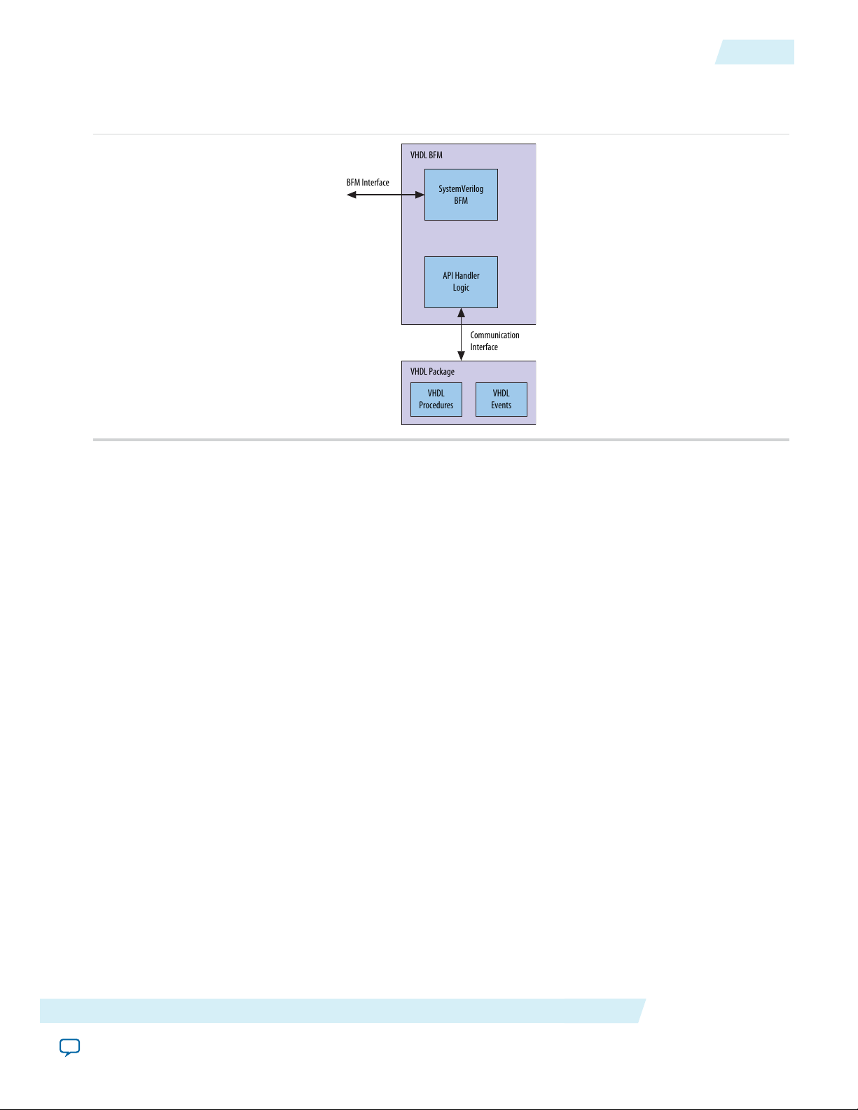
The VHDL BFM has four parts as shown in the figure below.
• SystemVerilog BFM—Contains the BFM implementation and behavioral model, and the SystemVerilog
API. The SystemVerilog code is IEEE encrypted for use in single-language simulators.
• VHDL package—Provides the VHDL API used to control the BFM and interface with your test program.
The package contains VHDL procedures and events.
• API handler logic—SystemVerilog logic block that translates your test program’s VHDL API calls to
SystemVerilog API calls. The SystemVerilog code is IEEE encrypted for use in single-language simulators.
Altera Corporation
Introduction to Avalon Verification IP Suite
Send Feedback
Page 14
API
Interaction
BFM Interface
VHDL BFM
Communication
Interface
VHDL
Procedures
VHDL
Events
VHDL Package
SystemVerilog
BFM
API Handler
Logic
Application Programming Interface
• API communication interface—Bridges the VHDL API to the API handler logic.
Figure 1-1: VHDL Component BFM
1-3
The monitor components use the SystemVerilog Assertion (SVA) language and are supported only by
simulators that support SVA, including:
• Modelsim-Altera Starter Edition (ASE)
• Synopsys VCS
• Mentor Graphics®Questa.
Application Programming Interface
Altera provides you with a set of application programming interfaces (API) for each Avalon Verification IP
Suite BFM. You can use the APIs to construct, instantiate, control, and query signals in all BFM components.
Your test programs must use only these public access methods and events to communicate with each BFM.
Note:
You can design custom verification environments that do not take advantage of the API. However,
Altera does not guarantee continued support or backwards compatibility custom methods.
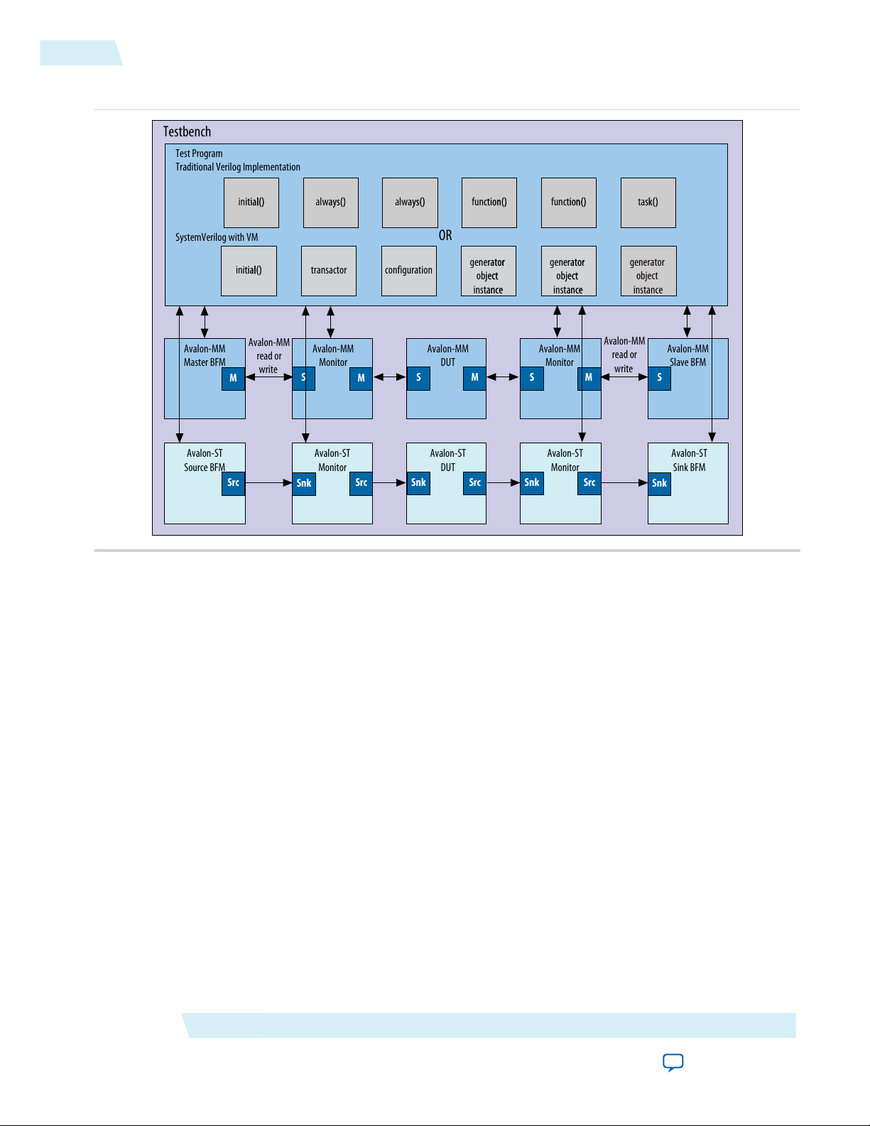
Application Example of BFMs
The figure below shows an Avalon-MM design with the following components:
• An Avalon-MM device under test (DUT) that includes both Avalon-MM master and slave interfaces
• An Avalon-ST DUT that includes both source and sink interfaces, although typical components might
include a single Avalon interface.
This figure illustrates it is possible to write a testbench using a traditional VerilogHDL implementation or
using SystemVerilog with VMM.
Introduction to Avalon Verification IP Suite
Send Feedback
Altera Corporation
Page 15
Testbench
Test Program
Traditional Verilog Implementation
OR
Avalon-MM
read or
write
SystemVerilog with VM
configuration
SRC
Avalon-MM
read or
write
S
Avalon-MM
Slave BFM
S
Avalon-MM
Monitor
Avalon-MM
Master BFM
Avalon-MM
DUT
M
SS
Avalon-MM
Monitor
Snk
Avalon-ST
Sink BFM
Snk
Avalon-ST
Monitor
Avalon-ST
Source BFM
Avalon-ST
DUT
Src
Src
Snk
Snk
Avalon-ST
Monitor
M
M
M
SrcSrc
transactor
generator
object
instance
generator
object
instance
generator
object
instance
generator
object
instance
initial()
initial() always() always() function() function() task()
1-4
Application Example of BFMs
Figure 1-2: Avalon Verification IP Suite Testbench for Avalon-MM and Avalon-ST Interfaces
To verify a component with Avalon-MM interfaces, insert a monitor between the master BFM and the slave
interface. To verify a component with Avalon-ST interfaces, insert a monitor between the source BFM and
sink interface. You can insert a second monitor between the slave or sink BFM and the master or source
interface of the DUT. You can inserted monitors anywhere in the system to provide protocol assertion
checking and functional coverage reporting.
The test program drives the stimulus to the DUTs. The test program also determines whether the DUT
behavior is correct, by analyzing the responses. The BFMs translate the test program stimuli. The BFMs
create the signalling for the Avalon-MM and Avalon-ST protocols. The monitors verify Avalon protocol
compliance and provide test coverage reports.
Altera Corporation
Introduction to Avalon Verification IP Suite
Send Feedback
Page 16

Clock Source BFM
www.altera.com
101 Innovation Drive, San Jose, CA 95134
2
Subscribe
Send Feedback
The Avalon Verification IP Suite includes a Clock Source BFM that you can use to generate a clock signal
for your testbench.
The Clock Source BFM is only supported in Qsys.Note:
Parameters
Table 2-1: Clock Source BFM Parameter Settings
Clock Source API
clock_start()
clock_start()Prototype:
DescriptionLegal ValuesDefault ValueOption
Specifies the clock rate in MHz.N/A10Clock rate
Arguments:
Verilog HDL: None
VHDL: N.A.
voidReturns:
Turns on the clock.Description:
Verilog HDLLanguage Support:
©
2014 Altera Corporation. All rights reserved. ALTERA, ARRIA, CYCLONE, ENPIRION, MAX, MEGACORE, NIOS, QUARTUS and STRATIX words
and logos are trademarks of Altera Corporation and registered in the U.S. Patent and Trademark Office and in other countries. All other
words and logos identified as trademarks or service marks are the property of their respective holders as described at
www.altera.com/common/legal.html. Altera warrants performance of its semiconductor products to current specifications in accordance with
Altera's standard warranty, but reserves the right to make changes to any products and services at any time without notice. Altera assumes
no responsibility or liability arising out of the application or use of any information, product, or service described herein except as expressly
agreed to in writing by Altera. Altera customers are advised to obtain the latest version of device specifications before relying on any published
information and before placing orders for products or services.
ISO
9001:2008
Registered
Page 17

2-2
Clock_stop()
Clock_stop()
clock_stop()Prototype:
Arguments:
get_run_state()
Arguments:
get_version()
Verilog HDL: None
VHDL: N.A.
voidReturns:
Turns off the clock.Description:
Verilog HDLLanguage support:
get_run_state()Prototype:
Verilog HDL: None
VHDL: N.A.
bitReturns:
Returns the state of the clock source; 1=running, 0=stop.Description:
Verilog HDLLanguage support:
Arguments:
Description:
string get_version()Prototype:
Verilog HDL: None
VHDL: N.A.
stringReturns:
Returns BFM version as a string of three integers separated by periods. For example,
version 10.1 sp1 is encoded as "10.1.1".
Verilog HDLLanguage support:
Altera Corporation
Clock Source BFM
Send Feedback
Page 18

Reset Source BFM
www.altera.com
101 Innovation Drive, San Jose, CA 95134
3
Subscribe
Send Feedback
The Avalon Verification IP Suite includes a Reset Source BFM that you can use to generate a reset signal in
your testbench.
Parameters
Table 3-1: Reset Source BFM Parameter Settings
On/OffOnAssert reset high
reset
Reset Source API
reset_assert
DescriptionLegal ValuesDefault ValueOption
Specifies the polarity of the reset signal. Turn on
this option to set the reset signal active high.
N/A0Cycles of initial
Specifies the number of cycles that the reset signal
is asserted at the initial stage of the simulation.
reset_assertPrototype:
Arguments:
Verilog HDL: None
VHDL: N.A.
void.Returns:
Asserts the reset signal.Description:
Verilog HDLLanguage support:
©
2014 Altera Corporation. All rights reserved. ALTERA, ARRIA, CYCLONE, ENPIRION, MAX, MEGACORE, NIOS, QUARTUS and STRATIX words
and logos are trademarks of Altera Corporation and registered in the U.S. Patent and Trademark Office and in other countries. All other
words and logos identified as trademarks or service marks are the property of their respective holders as described at
www.altera.com/common/legal.html. Altera warrants performance of its semiconductor products to current specifications in accordance with
Altera's standard warranty, but reserves the right to make changes to any products and services at any time without notice. Altera assumes
no responsibility or liability arising out of the application or use of any information, product, or service described herein except as expressly
agreed to in writing by Altera. Altera customers are advised to obtain the latest version of device specifications before relying on any published
information and before placing orders for products or services.
ISO
9001:2008
Registered
Page 19

3-2
reset_deassert
reset_deassert
reset_deassertPrototype:
Arguments:
get_version()
Arguments:
Description:
Verilog HDL: None
VHDL: N.A.
void.Returns:
Deasserts the reset signal.Description:
Verilog HDLLanguage support:
string get_version()Prototype:
Verilog HDL: None
VHDL: N.A.
String.Returns:
Returns BFM version as a string of three integers separated by periods. For example,
version 10.1 sp1 is encoded as "10.1.1".
Verilog HDLLanguage support:
Altera Corporation
Reset Source BFM
Send Feedback
Page 20

Avalon Interrupt Source and Interrupt Sink BFMs
www.altera.com
101 Innovation Drive, San Jose, CA 95134
4
Subscribe
Send Feedback
The Avalon Verification IP Suite includes Avalon Interrupt Source and Avalon Interrupt Sink BFMs for you
to generate interrupt signals in your testbench.
Parameters
Table 4-1: Clock Source BFM Parameter Settings
Interrupt Source
On/OffOnAssert IRQ high
On/OffOffAsynchronous
IRQ
DescriptionLegal ValuesDefault ValueOption
Specifies the polarity of the interrupt source signal.
Turn on this option to change the name of the
interrupt source signal port from irq to irq_n.
Specifies the width of the interrupt source signal.1–321IRQ width
Specifies whether the interrupt signal is asserted
or deasserted immediately after an API call or one
clock cycle after an API call. Turn on this option
to allow changes to the interrupt signal
immediately after an API call. Turn off this option
to allow changes to the interrupt signal on the
next clock edge.
©
2014 Altera Corporation. All rights reserved. ALTERA, ARRIA, CYCLONE, ENPIRION, MAX, MEGACORE, NIOS, QUARTUS and STRATIX words
and logos are trademarks of Altera Corporation and registered in the U.S. Patent and Trademark Office and in other countries. All other
words and logos identified as trademarks or service marks are the property of their respective holders as described at
www.altera.com/common/legal.html. Altera warrants performance of its semiconductor products to current specifications in accordance with
Altera's standard warranty, but reserves the right to make changes to any products and services at any time without notice. Altera assumes
no responsibility or liability arising out of the application or use of any information, product, or service described herein except as expressly
agreed to in writing by Altera. Altera customers are advised to obtain the latest version of device specifications before relying on any published
information and before placing orders for products or services.
1–10230VHDL BFM ID
Interrupt Sink
On/OffOnAssert IRQ high
For VHDL BFMs only. Use this option to assign
a unique number to each BFM in the testbench
design.
Specifies the polarity of the interrupt sink signal.
Turn on this option to change the name of the
interrupt source signal port from irq to irq_n.
Specifies the width of the interrupt source signal.1–321IRQ width
ISO
9001:2008
Registered
Page 21

4-2
Interrupt Source and Sink API
Interrupt Source and Sink API
clear_irq()
int clear_irq()Prototype:
Arguments:
Description:
get_irq()
get_irq()
Arguments:
Description:
Verilog HDL: interrupt_bit
VHDL: interrupt_bit, bfm_id, req_if(bfm_id)
voidReturns:
Asserts the interrupt signal and sets the interrupt signal to 0,
regardless of the value you set for Assert IRQ high in the parameter
editor.
Verilog HDL, VHDLLanguage Support:
get_irq()Prototype:
Verilog HDL: None
VHDL: irq, bfm_id, req_if(bfm_id)
logic[AV_IRQ_W-1:0]voidReturns:
Returns the current value of the register holding the latched
interrupt signal.
get_version()
get_version()
Arguments:
Description:
Altera Corporation
Verilog HDL, VHDLLanguage Support:
string get_version()Prototype:
Verilog HDL: None
VHDL: N.A.
StringReturns:
Returns BFM version as a string of three integers separated by
periods. For example, version 13.1 sp1 is encoded as "13.1.1".
Verilog HDLLanguage Support:
Avalon Interrupt Source and Interrupt Sink BFMs
Send Feedback
Page 22

set_irq()
set_irq()
set_irq()
set_irq()Prototype:
4-3
Arguments:
Description:
Verilog HDL: int interrupt_bit
VHDL: int interrupt_bit, bfm_id, req_if(bfm_id)
voidReturns:
Asserts the interrupt signal and sets the interrupt signal to 1,
regardless of the value you set for Assert IRQ high in the parameter
editor.
Verilog HDL, VHDLLanguage Support:
Avalon Interrupt Source and Interrupt Sink BFMs
Send Feedback
Altera Corporation
Page 23
Avalon-MM Master BFM
Avalon-MM
Master BFM
Avalon-MM
Slave Component
DUT
Testbench
Avalon-MM
Test Program
HDL HDL
www.altera.com
101 Innovation Drive, San Jose, CA 95134
5
Subscribe
Send Feedback
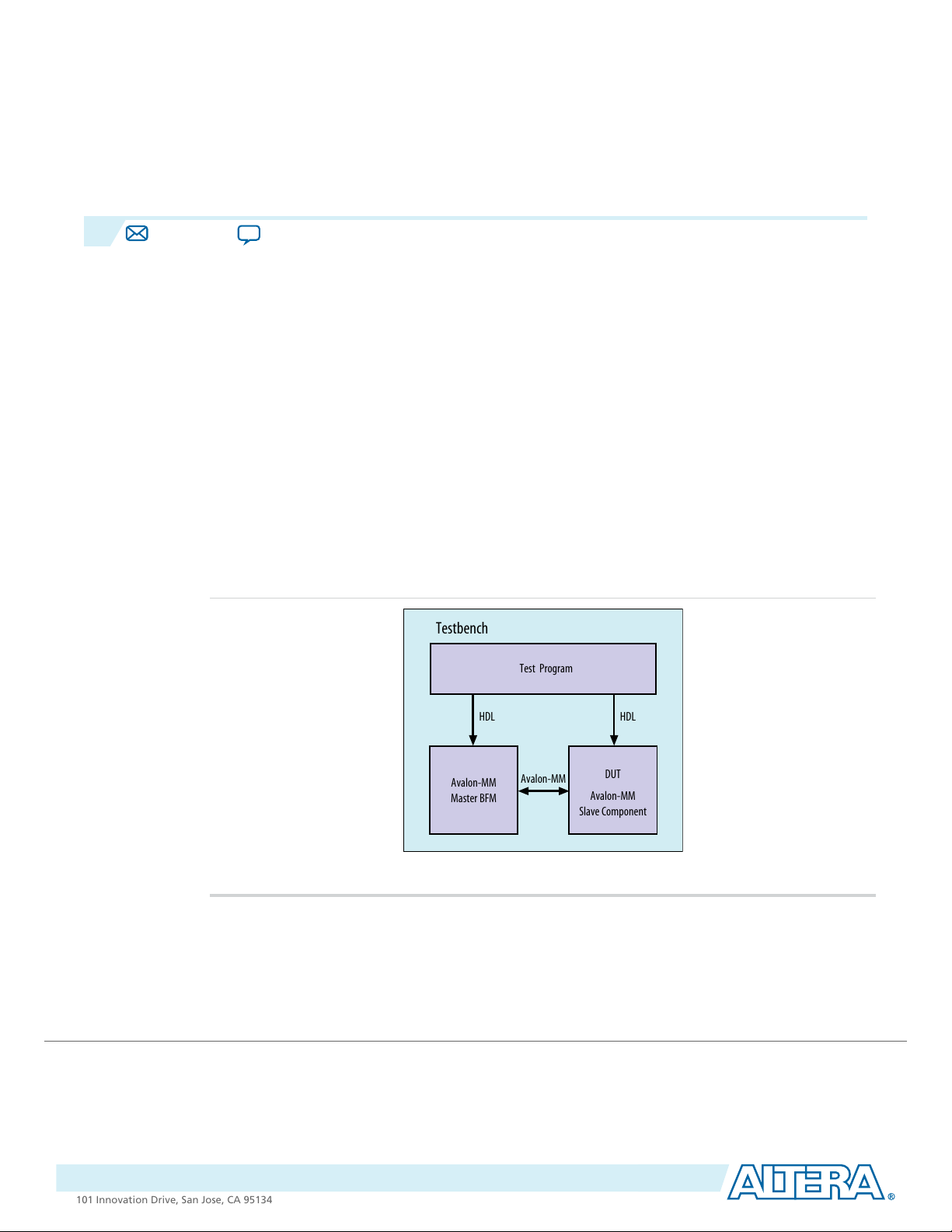
The Avalon-MM Master BFM implements the Avalon-MM interface protocol, including: read, write, burst
read, and burst write. The figure below shows the top-level modules for a testbench using the Avalon-MM
BFM to verify an Avalon-MM slave component. The typical testbench includes the folowing components:
• The Avalon-MM Master BFM
• A test program
• The DUT that includes an Avalon-MM slave interface
Using the Avalon-MM BFM created by Altera, third-party, has the following advantage. It highlights any
misinterpretation of the Avalon-MM protocol that might be missed in a testbench designed by a single
engineer.
Note:
The BFMs allow illegal transactions so that you can test the error-handling functionality of your
DUT. Consequently, the BFMs cannot be relied upon to guarantee protocol compliance. The Avalon
Monitor components verify protocol compliance.
Figure 5-1: Top-Level Module to Verify an Avalon-MM Slave Device
Related Information
Avalon Interface Specifications
©
2014 Altera Corporation. All rights reserved. ALTERA, ARRIA, CYCLONE, ENPIRION, MAX, MEGACORE, NIOS, QUARTUS and STRATIX words
and logos are trademarks of Altera Corporation and registered in the U.S. Patent and Trademark Office and in other countries. All other
words and logos identified as trademarks or service marks are the property of their respective holders as described at
www.altera.com/common/legal.html. Altera warrants performance of its semiconductor products to current specifications in accordance with
Altera's standard warranty, but reserves the right to make changes to any products and services at any time without notice. Altera assumes
no responsibility or liability arising out of the application or use of any information, product, or service described herein except as expressly
agreed to in writing by Altera. Altera customers are advised to obtain the latest version of device specifications before relying on any published
information and before placing orders for products or services.
ISO
9001:2008
Registered
Page 24
writedata[31:0]
D1 D3
CLK
read
transaction1 transaction2
trans3
trans4
write
T
init
T
init
S
ci_1
T
idle
S
ci_2
S
ci_3
S
ci_4
transactionid
waitrequest
byteenable[3:0]
T
wr
T
wt_1
T
wt_2
T
ID_4
writeresponse
writeid
ID_1
ID_3
readdatavalid
readdata
D2 D4
T
rl_1
T
rl_2
S
rc_4,
S
rc_2
S
atc
readresponse
readid
ID_2
ID_4
writeresponsevalid
T
wrl_1
S
rc_1
T
ID_1
T
ID_2
T
ID_3
S
rc_3
D2 D4
5-2
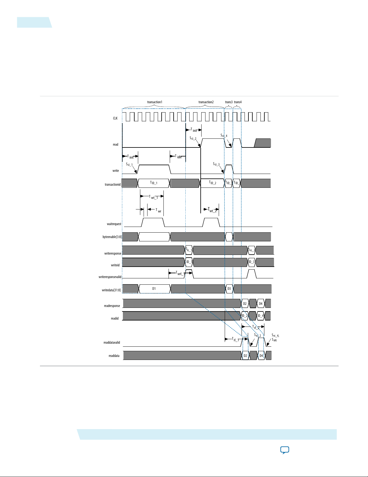
Timing
Timing
The following timing diagram illustrates the sequence of events for an Avalon-MM Master BFM. The Master
BFM drives interleaved writes and reads when the readdatavalid signal is present. This diagram serves as
a reference for the following discussion of API and events.
Figure 5-2: Avalon-MM Master Driving Interleaved Write and Read Transactions
Altera Corporation
Avalon-MM Master BFM
Send Feedback
Page 25

Table 5-1: Key to the Annotations
The following table lists the annotations used in the figure.
Timing
5-3
DescriptionSymbol
T
T
T
T
T
init
wt_1
wr
idle
rl_1
rl_2
wrl_1
The initial command latency, which is two cycles for transactions 1 and 2. This time is set by
the API command set_command_init_latency.
The response wait time, which is three cycles. This time is determined by the number of cycles
that the waitrequest signal is asserted by the slave.The program gets this value using the get_
response_wait_time command.
waitrequest is always sampled #1 after the falling edge of clk.T
The idle time after each transaction. This time is set by the command set_command_idle.T
The response latency for the first read, which is 3 cycles. This is the time between the read
command acceptance and the read response provided by the slave. The program gets this time
using the get_response_latency command.
If an Avalon-MM slave component defines the readLatency interface property, the
readdatavalid signal is not used. The readdatavalid signal is not necessary because the slave
component has a fixed read latency.
For more information refer to the Avalon Interface Specifications.
The response latency for the second read, which is 3 cycles. The program gets this time using
the get_response_latency command.
The write response latency for the first write, which is 3 cycles. This is the time between when
the write command acceptance and the write response is provided by the slave. The program
gets this time using the get_response_latency command.
S
ci_1–Sci_4
rc_1,Src_3
rc_2,Src_4
atc
ID_1–TID_
4
Signals when write or read commands are presented on the interface. The event name is signal_
command_issued.
Signals write responses. The event name is signal_response_complete.S
Signals read responses. The event name is signal_response_complete.S
Signals the end of the test. The event name is signal_all_transactions_completeS
Reference number to identify each read or write transaction.T
Reference number to identify each write transaction.ID_1, ID_3
Reference number to identify each read transaction.ID_2, ID_4
Avalon-MM Master BFM
Send Feedback
Altera Corporation
Page 26
CLK
read
write
waitrequest
byteenable[3:0]
writedata[31:0]
readdata
D1
D2
T
init
T
init
S
ci_1
T
wt_1
T
wt_2
S
ci_2
S
rc_1,
S
atc
T
wr
transaction5
transaction6
T
idle
5-4
Timing
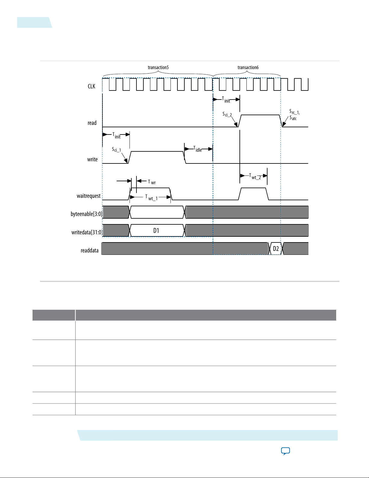
Figure 5-3: Avalon-MM Master Driving Write and Read Transactions with No readdatavalid Signal
The timing in the following figure shows the sequence of events for an Avalon-MM Master BFM. The
Avalon-MM Master BFM drives a write followed by a read when the readdatavalid signal is not present.
Table 5-2: Key to the Annotations
The following table lists the annotations used in this figure.
T
init
The initial command latency, which is 2 cycles for transactions 1 and 2. This time is set by the
API command set_command_init_latency.
T
wt_1
T
wt_2
The response wait time, which is 3 cycles. This time is determined by the number of cycles that
the waitrequest signal is asserted by the slave.The program gets this value using the get_
response_wait_time command.
The response wait time for the first read, which is 2 cycles. This time is determined by the
number of cycles that the waitrequest signal is asserted by the slave.The program gets this
value using the get_response_wait_time command.
waitrequest is always sampled #1 after the falling edge of clk.T
The idle time after a transaction. This time is set by the command set_command_idle.T
wr
idle
Altera Corporation
DescriptionSymbol
Avalon-MM Master BFM
Send Feedback
Page 27

Block Diagram
DescriptionSymbol
5-5
S
ci_1–Sci_2
rc_1
atc
Signals when write and read commands are presented on the interface. The event name is
signal_command_issued.
Signals the first read response. The event name is signal_response_complete.S
Signals the end of the test. The event name is signal_all_transactions_complete.S
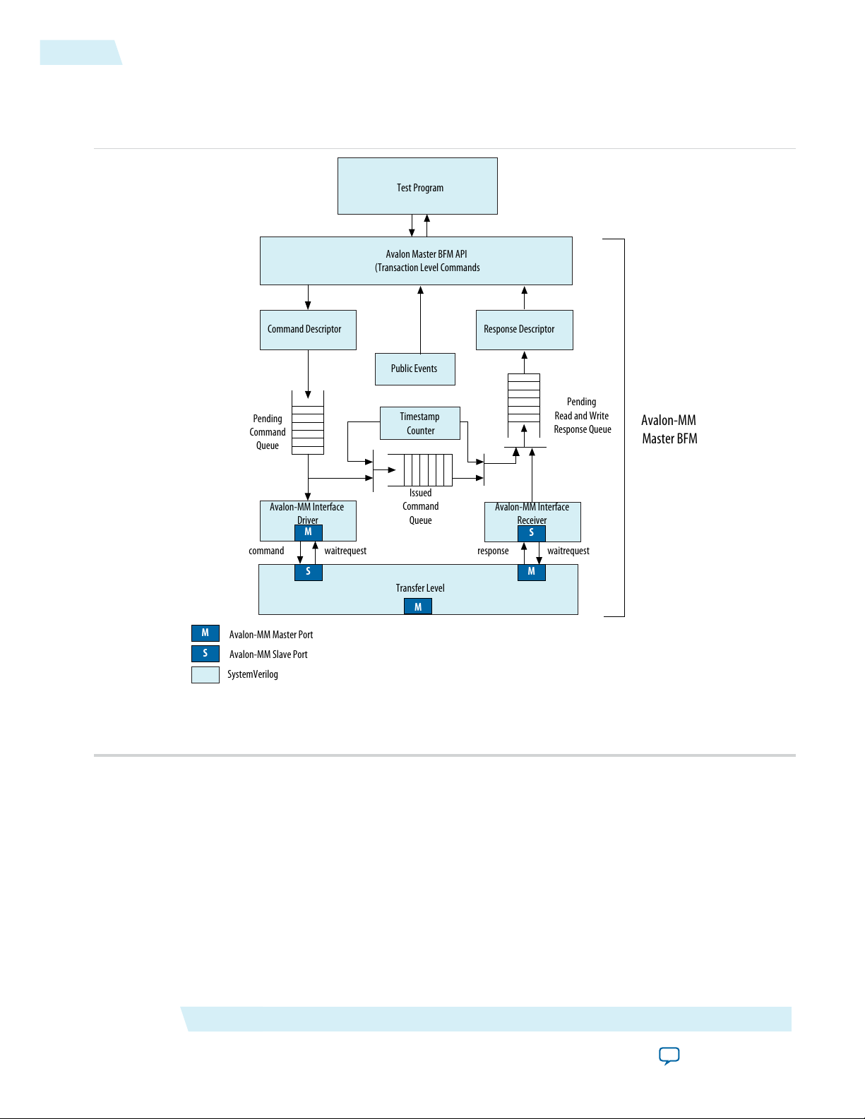
Block Diagram
The following figure provides a block diagram of the Avalon-MM Master BFM. As this figure illustrates,
the BFM includes the following major blocks:
• Avalon-MM Master API—Provides methods to create Avalon-MM transactions and query the state of
all queues.
• Command Descriptor—Accumulates the fields of an Avalon-MM command transaction using the
set_command API call. Inserts completed commands onto the pending command queue.
• Avalon-MM Interface Driver—Issues transfers to the system interconnect fabric and holds each transfer
until waitrequest is deasserted. For burst transfers, there is a separate transfer for each word of the
burst. The system interconnect fabric can assert waitrequest for each word of the burst, as necessary.
• Timestamp Counter—Records a timestamp with commands for use in timing calculations. The driver
and monitor both use the timestamp counter for timing calculations.
• Avalon-MM Interface Monitor—Monitors the system interconnect fabric and records responses for read
transfers in the response queue.
• Response Descriptor—Collects information about completed transactions using the
get_response_<rolename> API calls. The testbench uses this information for further analysis.
Avalon-MM Master BFM
Send Feedback
Altera Corporation
Page 28
Command Descriptor
Timestamp
Counter
Avalon Master BFM API
(Transaction Level Commands
Transfer Level
Avalon-MM Interface
Receiver
Response Descriptor
Pending
Command
Queue
Issued
Command
Queue
Pending
Read and Write
Response Queue
Avalon-MM Interface
Driver
command waitrequest response waitrequest
Test Program
M
S
M
M
S
S
M
Avalon-MM Master Port
Avalon-MM Slave Port
SystemVerilog
Avalon-MM
Master BFM
Public Events
5-6
Parameters
• Public Events—Provides status response that arrives together with the data. The public event signals
indicate the status of the Master’s request, such as successful completion, timeout, or error.
Figure 5-4: Block Diagram of the Avalon-MM Master BFM
Parameters
The Avalon-MM BFM supports the full range of signals defined for the Avalon-MM master interface. You
can customize the Avalon-MM master interface using the parameters described in the following table.
Altera Corporation
Avalon-MM Master BFM
Send Feedback
Page 29

Table 5-3: Parameters for the Avalon-MM Master BFM
Parameters
5-7
signal
Parameter
Value
Port Widths
N/A8Symbol width
Port Enables
DescriptionLegal ValuesDefault
Address width in bits.N/A32Address width
Data symbol width in bits. The symbol width should be
8 for byte-oriented interfaces.
Read response signal width in bits.N/A8Read Response width
Write response signal width in bits.N/A8Write Response width
Parameters
Number of symbols per word.N/A4Number of symbols
The width of the burst count in bits.N/A3Burstcount width
When On, the interface includes a read pin.On/OffOnUse the read signal
When On, the interface includes a write pin.On/OffOnUse the write signal
When On, the interface includes address pins.On/OffOnUse the address signal
When On, the interface includes byteenable pins.On/OffOnUse the byteenable
signal
signal
signal
transfer signal
signal
signal
signal
signal
When On, the interface includes burstcount pins.On/OffOnUse the burstcount
When On, the interface includes a readdata pin.On/OffOnUse the readdata signal
When On, the interface includes a readdatavalid pin.On/OffOnUse the readdatavalid
When On, the interface includes a writedata pin.On/OffOnUse the writedata signal
When On, the interface includes writedata pinsOn/OffOffUse the begintransfer
On/OffOffUse the beginburst-
When On, the interface includes a beginbursttransfer
pins.
When On, the interface includes an arbiterlock pin.On/OffOffUse the arbiterlock
When On, the interface includes a lock pin.On/OffOffUse the lock signal
When On, the interface includes a debugaccess pin.On/OffOffUse the debugaccess
When On, the interface includes a waitrequest pin.On/OffOnUse the waitrequest
When On, the interface includes a transactionid pin.On/OffOffUse the transactionid
Avalon-MM Master BFM
Send Feedback
Altera Corporation
Page 30

5-8
Parameters
signals
signals
high
Parameter
DescriptionLegal ValuesDefault
Value
When On, the interface includes a writeresponse pin.On/OffOffUse the write response
When On, the interface includes a readresponse pin.On/OffOffUse the read response
When On, the interface includes a clken pin.On/OffOffUse the clken signals
Port Polarity
When On, reset is asserted high.On/OffOnAssert reset high
When On, waitrequest is asserted high.On/OffOnAssert waitrequest high
When On, read is asserted high.On/OffOnAssert read high
When On, write is asserted high.On/OffOnAssert write high
When On, byteenable is asserted high.On/OffOnAssert byteenable high
When On, readdatavalid is asserted high.On/OffOnAssert readdatavalid
When On, arbiterlock is asserted high.On/OffOnAssert arbiterlock high
When On, lock is asserted high.On/OffOnAssert lock high
boundaries only
reads
(cycles)
(cycles)
Burst Attributes
On/OffOnLinewrap burst
Miscellaneous
N/A1Maximum pending
N/A1Fixed read latency
0–10230VHDL BFM ID
N/A1Fixed read wait time
When On, the address for bursts wraps instead of
incrementing. With a wrapping burst, when the address
reaches a burst boundary, it wraps back to the previous
burst boundary. Consequently, only the low order bits
are used for addressing.
When On, memory bursts are aligned to the address size.On/OffOnBurst on burst
The maximum number of pending reads that can be
queued by the slave.
Sets the read latency for fixed-latency slaves. Not used on
interfaces that include the readdatavalid signal.
For VHDL BFMs only. Use this option to assign a unique
number to each BFM in the testbench design.
Timing
For master interfaces that do not use the waitrequest
signal. The read wait time indicates the number of cycles
before the master responds to a read. The timing is as if
the master asserted waitrequest for this number of
cycles.
(cycles)
Altera Corporation
N/A0Fixed write wait time
For master interfaces that do not use the waitrequest
signal. The write wait time indicates the number of cycles
before the master accepts a write.
Avalon-MM Master BFM
Send Feedback
Page 31

Avalon-MM Master BFM API
5-9
Parameter
Value
Signals
WORDSSet master interface
address type to symbols
or words
Avalon-MM Master BFM API
all_transactions_complete()
bit all_()Prototype:
Arguments:
Verilog HDL: None
VHDL:transactions_complete_status, bfm_id, req_if(bfm_id)
bit.Returns:
DescriptionLegal ValuesDefault
Specifies whether to turn on the register stage.On/OffOffRegistered waitrequest
Specifies whether to register incoming signals.On/OffOffRegistered Incoming
Interface Address Type
Sets slave interface address type to symbols or words.WORDS/
SYMBOLS
Description:
Queries the BFM component to determine whether all issued commands have
been completed. A return value of 1 means that there are no more transactions
in the transaction queue or in progress.
Verilog HDL, VHDLLanguage support:
event_all_transactions_complete()
event_all_transactions_complete()Prototype:
Arguments:
Verilog HDL: N.A.
VHDL: bfm_id
voidReturns:
Notifies the testbench that all commands have completed.Description:
VHDLLanguage support:
Avalon-MM Master BFM
Send Feedback
Altera Corporation
Page 32

5-10
event_command_issued()
event_command_issued()
event_command_issued()Prototype:
Arguments:
Verilog HDL: N.A.
VHDL: bfm_id
voidReturns:
Notifies the testbench a command was driven to the bus.Description:
VHDLLanguage support:
event_max_command_queue_size()
event_max_command_queue_size()Prototype:
Arguments:
Verilog HDL: N.A.
VHDL: bfm_id
voidReturns:
Notifies the testbench that the command queue size reached its maximum limit.Description:
VHDLLanguage support:
event_min_command_queue_size()
event_min_command_queue_size()Prototype:
Arguments:
Verilog HDL: N.A.
VHDL: bfm_id
voidReturns:
Notifies the testbench that the command queue size reached its minimum limit.Description:
VHDLLanguage support:
event_read_response_complete()
event_read_response_complete()Prototype:
Arguments:
Verilog HDL: N.A.
VHDL: bfm_id
voidReturns:
Notifies the testbench that a read response was received.Description:
VHDLLanguage support:
Altera Corporation
Avalon-MM Master BFM
Send Feedback
Page 33

event_response_complete()
event_response_complete()Prototype:
event_response_complete()
5-11
Arguments:
Verilog HDL: N.A.
VHDL: bfm_id
voidReturns:
Notifies the testbench that a read/write response was received.Description:
VHDLLanguage support:
event_write_response_complete()
event_write_response_complete()Prototype:
Arguments:
Verilog HDL: N.A.
VHDL: bfm_id
voidReturns:
Notifies the testbench that a write response was received.Description:
VHDLLanguage support:
get_command_issued_queue_size()
Arguments:
Description:
int get_command_issued_queue_size()Prototype:
Verilog HDL: None
VHDL: command_issued_queue_size, bfm_id, req_if(bfm_id)
intReturns:
Queries the issued command queue to determine the number of commands that
have been driven to the system interconnect fabric, but not completed.
Verilog HDL, VHDLLanguage support:
Avalon-MM Master BFM
Send Feedback
Altera Corporation
Page 34

5-12
get_command_pending_queue_size()
get_command_pending_queue_size()
int get_command_pending_queue_size()Prototype:
Arguments:
Verilog HDL: None
VHDL: command_pending_queue_size, bfm_id, req_if(bfm_id)
intReturns:
Description:
Queries the command queue to determine number of pending commands waiting
to be driven out as Avalon requests.
Verilog HDL, VHDLLanguage support:
get_read_response_queue_size()
int get_read_response_queue_size()Prototype:
Arguments:
Description:
Verilog HDL: None
VHDL: read_response_queue_size, bfm_id, req_if(bfm_id)
intReturns:
Queries the read response queue to determine number of response descriptors
currently stored in the BFM. This is the number of responses the test program
can immediately remove from the response queue for further processing.
Verilog HDL, VHDLLanguage support:
get_response_address()
Arguments:
Description:
bit [AV_ADDRESS_W-1:0] get_response_address()Prototype:
Verilog HDL: None
VHDL: response_address, bfm_id, req_if(bfm_id)
bitReturns:
Returns the transaction address in the response descriptor that has been removed
from the response queue.
Verilog HDL, VHDLLanguage support:
Altera Corporation
Avalon-MM Master BFM
Send Feedback
Page 35

get_response_byte_enable()
bit [AV_NUMSYMBOLS-1:0] get_response_byte_enable(int index)Prototype:
get_response_byte_enable()
5-13
Arguments:
Verilog HDL: index
VHDL: response_byte_enable, index, bfm_id, req_if(bfm_id)
bitReturns:
Description:
Returns the value of the byte enables in the response descriptor that has been
removed from the response queue. Each cycle of a burst response is addressed
individually by the specified index.
Verilog HDL, VHDLLanguage support:
get_response_burst_size()
bit [AV_BURSTCOUNT_W-1:0]get_response_burst_size()Prototype:
Arguments:
Description:
Verilog HDL: None
VHDL: response_burst_size, bfm_id, req_if(bfm_id)
bitReturns:
Returns the size of the response transaction burst count in the response descriptor
that has been removed from the response queue.
Verilog HDL, VHDLLanguage support:
get_response_data()
Arguments:
Description:
bit [AV_DATA_W-1:0] get_response_data(int index)Prototype:
Verilog HDL: index
VHDL: response_data, index, bfm_id, req_if(bfm_id)
bitReturns:
Returns the transaction read data in the response descriptor that has been removed
from the response queue. Each cycle in a burst response is addressed individually
by the specified index. In the case of read responses, the data is the data captured
on the avm_readdata interface pin. In the case of write responses, the data on the
driven avm_writedata pin is captured and reflected here.
Verilog HDL, VHDLLanguage support:
Avalon-MM Master BFM
Send Feedback
Altera Corporation
Page 36

5-14
get_response_latency()
get_response_latency()
int get_response_latency(int index)Prototype:
Arguments:
Verilog HDL: index
VHDL: response_data, index, bfm_id, req_if(bfm_id)
bitReturns:
Description:
Returns the transaction read latency in the response descriptor that has been
removed from the response queue. Each cycle in a burst read has its own latency
entry.
Verilog HDL, VHDLLanguage support:
get_response_queue_size()
int get_response_queue_size()Prototype:
Arguments:
Description:
Verilog HDL: None
VHDL: response_queue_size, bfm_id, req_if(bfm_id)
intReturns:
Queries the response queue to determine number of response descriptors currently
stored in the BFM. This is the number of responses the test program can
immediately remove from the response queue for further processing.
get_response_read_id()
Arguments:
Description:
Verilog HDL, VHDLLanguage support:
[AV_TRANSACTIONID_W-1:0] get_response_read_id()Prototype:
Verilog HDL: None
VHDL: response_read_id, bfm_id, req_if(bfm_id)
AvalonTransactionId_tReturns:
Returns the read id of the transaction in the response descriptor that has been
removed from the response queue.
Verilog HDL, VHDLLanguage support:
Altera Corporation
Avalon-MM Master BFM
Send Feedback
Page 37

get_response_read_response()
get_response_read_response()
5-15
Prototype:
Arguments:
Description:
get_response_request()
Prototype:
Arguments:
Description:
bit[2**(AV_BURSTCOUNT_W-1) - 1:0] [AV_READRESPONSE_W-1:0] get_
response_read_response(int index)
Verilog HDL: int index
VHDL: response_read_response, int index, bfm_id, req_if(bfm_id)
AvalonReadResponse_tReturns:
Returns the transaction read status in the response descriptor that has been
removed from the response queue.
Verilog HDL, VHDLLanguage support:
enum int[REQ_READ = 0, REQ_WRITE = 1, RED_IDLE = 2] get_response_
request()
Verilog HDL: None
VHDL: response_request, bfm_id, req_if(bfm_id)
Request_tReturns:
Returns the transaction command type in the response descriptor that has been
removed from the response queue.
Verilog HDL, VHDLLanguage support:
get_response_wait_time()
int get_response_wait_time(int index)Prototype:
Arguments:
Description:
Verilog HDL: index
VHDL: response_wait_time, index, bfm_id, req_if(bfm_id)
intReturns:
Returns the wait latency for transaction in the response descriptor that has been
removed from the response queue. Each cycle in a burst has its own wait latency
entry.
Verilog HDL, VHDLLanguage support:
Avalon-MM Master BFM
Send Feedback
Altera Corporation
Page 38

5-16
get_response_write_id()
get_response_write_id()
bit [AV_TRANSACTIONID_W-1:0] get_response_write_id()Prototype:
Arguments:
Verilog HDL: None
VHDL: response_write_id, index, bfm_id, req_if(bfm_id)
AvalonTransactionId_tReturns:
Description:
Returns the write id of the transaction in the response descriptor that has been
removed from the response queue.
Verilog HDL, VHDLLanguage support:
get_response_write_response()
Prototype:
Arguments:
Description:
bit [2**(AV_BURSTCOUNT_W-1)-1:0] [AV_WRITERESPONSE_W-1:0] get_
response_write_response(int index)
Verilog HDL: int index
VHDL: response_write_response, int index, bfm_id, req_if(bfm_id)
AvalonWriteResponse_tReturns:
Returns the transaction write status in the response descriptor that has been
removed from the response queue.
Verilog HDL, VHDLLanguage support:
get_write_response_queue_size()
int get_write_response_queue_size()Prototype:
Arguments:
Description:
Verilog HDL: None
VHDL: write_response_queue_size, index, bfm_id, req_if(bfm_id)
intReturns:
Queries the write response queue to determine number of response descriptors
currently stored in the BFM. This is the number of responses the test program
can immediately pop off the response queue for further processing.
Verilog HDL, VHDLLanguage support:
Altera Corporation
Avalon-MM Master BFM
Send Feedback
Page 39

get_version()
get_version()
string get_version()Prototype:
5-17
Arguments:
Description:
init()
Arguments:
Verilog HDL: None
VHDL: N.A.
StringReturns:
Returns BFM version as a string of three integers separated by periods. For example,
version 14.1 sp1 is encoded as "14.1.1".
Verilog HDLLanguage support:
initPrototype:
Verilog HDL: None
VHDL: bfm_id, req_if(bfm_id)
voidReturns:
Initializes the Avalon-MM master interface.Description:
Verilog HDL, VHDLLanguage support:
pop_response()
Arguments:
Description:
void pop_response()Prototype:
Verilog HDL: None
VHDL: bfm_id, req_if(bfm_id)
voidReturns:
Removes the oldest response descriptor from the response queue, such that
transaction information is available using the get_response_<rolename>
commands.
Verilog HDL, VHDLLanguage support:
Avalon-MM Master BFM
Send Feedback
Altera Corporation
Page 40

5-18
push_command()
push_command()
void push_command()Prototype:
Arguments:
Description:
set_clken()
Arguments:
Verilog HDL: None
VHDL: bfm_id, req_if(bfm_id)
voidReturns:
Inserts the fully populated transaction descriptor onto the pending transaction
command queue.
Verilog HDL, VHDLLanguage support:
void set_clken(bit state)Prototype:
Verilog HDL: bit state
VHDL: bit state, bfm_id, req_if(bfm_id)
voidReturns:
Sets the assertion and deassertion of the clock enable signal.Description:
Verilog HDL, VHDLLanguage support:
set_command_address()
void set_command_address(bit[AV_ADDRESS_W-1:0]addr)Prototype:
Arguments:
Verilog HDL: addr
VHDL: addr, bfm_id, req_if(bfm_id)
voidReturns:
Sets the transaction address in the command descriptor.Description:
Verilog HDL, VHDLLanguage support:
Altera Corporation
Avalon-MM Master BFM
Send Feedback
Page 41

set_command_arbiterlock()
void set_command_arbiterlock (bit state)Prototype:
set_command_arbiterlock()
5-19
Arguments:
Verilog HDL: bit state
VHDL: bit state, bfm_id, req_if(bfm_id)
voidReturns:
Description:
Controls the assertion or deassertion of the arbiterlock interface signal. The
arbiterlock control is on the transaction boundaries and is not used when the
Avalon-MM Master BFM is operating in burst mode.
Verilog HDL, VHDLLanguage support:
set_command_byte_enable()
Prototype:
Arguments:
Description:
void set_command_byte_enable(bit[AV_NUMSYMBOLS-1:0] byte_enable,
int index)
Verilog HDL: byte_enable, index
VHDL: byte_enable, index, bfm_id, req_if(bfm_id)
voidReturns:
Sets the transaction byte enable field for the cycle of the burst command descriptor
indicated by index. This field applies to both read and write operations.
Verilog HDL, VHDLLanguage support:
set_command_burst_count()
void set_command_burst_count(bit[AV_BURSTCOUNT_W-1:0] burst_count)Prototype:
Arguments:
Description:
Verilog HDL: burst_count
VHDL: burst_count, bfm_id, req_if(bfm_id)
voidReturns:
Sets the value driven on the Avalon interface burstcount pin. Generates a warning
message if the specified burst_count is out of range. Not available if the USE_
BURSTCOUNT parameter is false.
Verilog HDL, VHDLLanguage support:
Avalon-MM Master BFM
Send Feedback
Altera Corporation
Page 42

5-20
set_command_burst_size()
set_command_burst_size()
void set_command_burst_size (bit[AV_BURSTCOUNT_W-1:0] burst_size)Prototype:
Arguments:
Description:
set_command_data()
Arguments:
Description:
Verilog HDL: burst_size
VHDL: burst_size, bfm_id, req_if(bfm_id)
voidReturns:
Sets the transaction burst count in the command descriptor to determine the
number of words driven on the write burst command. The value might be different
from the value specified in set_command_burst_count to generate illegal traffic
for testing. Generates a warning if the value is different.
Verilog HDL, VHDLLanguage support:
void set_command_data(bit[AV_DATA_W-1:0] data, int index)Prototype:
Verilog HDL: data, index
VHDL: data, index,bfm_id, req_if(bfm_id)
voidReturns:
Sets the transaction write data in the command descriptor. For burst transactions,
the command descriptor holds an array of data, with each element individually
set by this method.
Verilog HDL, VHDLLanguage support:
set_command_debugaccess()
void set_command_debugaccessPrototype:
Arguments:
Description:
Verilog HDL: bit state
VHDL: bit state, bfm_id, req_if(bfm_id)
voidReturns:
Controls the assertion or deassertion of the debugaccess interface signal. The
debugaccess control is on transaction boundaries.
Verilog HDL, VHDLLanguage support:
Altera Corporation
Avalon-MM Master BFM
Send Feedback
Page 43

set_command_idle()
set_command_idle()
void set_command_idle(int idle, int index)Prototype:
5-21
Arguments:
Verilog HDL: int idle, int index
VHDL: int idle, int index, bfm_id, req_if(bfm_id)
voidReturns:
Description:
Sets idle cycles at the end of each transaction cycle. For read commands, idle cycles
are inserted at the end of the command cycle. For burst write commands, idle
cycles are inserted at the end of each write data cycle within the burst.
Verilog HDL, VHDLLanguage support:
set_command_init_latency()
void set_command_init_latency(int cycles)Prototype:
Arguments:
Verilog HDL: cycles
VHDL: cycles, bfm_id, req_if(bfm_id)
voidReturns:
Sets the number of cycles to postpone the start of a command.Description:
Verilog HDL, VHDLLanguage support:
set_command_lock()
Arguments:
Description:
void set_command_lock (bit state)Prototype:
Verilog HDL: bit state
VHDL: bit state, bfm_id, req_if(bfm_id)
voidReturns:
Controls the assertion or deassertion of the lock interface signal. Lock control is
on the transaction boundaries. It is not used when the Avalon-MM Master BFM
is operating in burst mode.
Verilog HDL, VHDLLanguage support:
Avalon-MM Master BFM
Send Feedback
Altera Corporation
Page 44

5-22
set_command_request()
set_command_request()
void set_command_request(Request_t request)Prototype:
Arguments:
Verilog HDL: Request_t request
VHDL: Request_t request, bfm_id, req_if(bfm_id)
voidReturns:
Description:
Sets the transaction type to read or write in the command descriptor. The
enumeration type defines REQ_READ = 0 and REQ_WRITE = 1.
Verilog HDL, VHDLLanguage support:
set_command_timeout()
void set_command_timeout(int cycles)Prototype:
Arguments:
Description:
Verilog HDL: int cycles
VHDL: int cycles, bfm_id, req_if(bfm_id)
voidReturns:
Sets the number of elapsed cycles between waiting for a waitrequest and when
time out is asserted. Disables time-out by setting the value to 0.
Verilog HDL, VHDLLanguage support:
set_command_transaction_id()
void set_command_transaction_id(bit[AV_TRANSACTIONID_W-1:0] id)Prototype:
Arguments:
AvalonTransactionId_t id.
Verilog HDL: tid
VHDL: tid , bfm_id,req_if(bfm_id)
voidReturns:
Sets the transaction id number in the command descriptor.Description:
Verilog HDL, VHDLLanguage support:
Altera Corporation
Avalon-MM Master BFM
Send Feedback
Page 45

set_command_write_response_request()
void set_command_write_response_request (logic request)Prototype:
set_command_write_response_request()
5-23
Arguments:
Verilog HDL: request
VHDL: request, bfm_id, req_if(bfm_id)
voidReturns:
Description:
Sets the flag that enables or disables the write response requests in the command
descriptor.
Verilog HDL, VHDLLanguage support:
set_max_command_queue_size()
void set_max_command_queue_size(int size)Prototype:
Arguments:
Verilog HDL: int size
VHDL: int size, bfm_id, req_if(bfm_id)
voidReturns:
Sets the pending command queue size maximum threshold.Description:
Verilog HDL, VHDLLanguage support:
set_min_command_queue_size()
void set_min_command_queue_size(int size)Prototype:
Arguments:
Verilog HDL: int size
VHDL: int size, bfm_id, req_if(bfm_id)
voidReturns:
Sets the pending command queue size minimum threshold.Description:
Verilog HDL, VHDLLanguage support:
Avalon-MM Master BFM
Send Feedback
Altera Corporation
Page 46

5-24
set_response_timeout()
set_response_timeout()
void set_response_timeout(int cycles)Prototype:
Arguments:
Verilog HDL: int cycles
VHDL: int cycles, bfm_id, req_if(bfm_id)
voidReturns:
Description:
Sets the number of cycles that may elapse before response time out. Disable timeout by setting the value to 0.
Verilog HDL, VHDLLanguage support:
signal_all_transactions_complete
signal_all_transactions_completePrototype:
Arguments:
Verilog HDL: None
VHDL: N.A.
voidReturns:
Signals that all queued transactions have completed.Description:
Verilog HDLLanguage support:
signal_command_issued
signal_command_issuedPrototype:
Arguments:
Verilog HDL: None
VHDL: N.A.
voidReturns:
Signals that the currently pending command has been driven to the interface.Description:
Verilog HDLLanguage support:
Altera Corporation
Avalon-MM Master BFM
Send Feedback
Page 47

signal_fatal_error
signal_fatal_error
signal_fatal_errorPrototype:
5-25
Arguments:
Verilog HDL: None
VHDL: N.A.
voidReturns:
Notifies the testbench that a fatal error has occured in this module.Description:
Verilog HDLLanguage support:
signal_max_command_queue_size
signal_max_command_queue_sizePrototype:
Arguments:
Description:
Verilog HDL: None
VHDL: N.A.
voidReturns:
Signals that the maximum pending transaction queue size threshold has been
exceeded.
Verilog HDLLanguage support:
signal_min_command_queue_size
signal_min_command_queue_sizePrototype:
Arguments:
Verilog HDL: None
VHDL: N.A.
voidReturns:
Signals that the pending transaction queue size is below the minimum threshold.Description:
Verilog HDLLanguage support:
Avalon-MM Master BFM
Send Feedback
Altera Corporation
Page 48

5-26
signal_read_response_complete
signal_read_response_complete
signal_read_response_completePrototype:
Arguments:
Verilog HDL: None
VHDL: N.A.
voidReturns:
Description:
Signals that the read response has been received and inserted into the response
queue.
Verilog HDLLanguage support:
signal_response_complete
signal_response_completePrototype:
Arguments:
Description:
Verilog HDL: None
VHDL: N.A.
voidReturns:
Triggers when either signal_read_response_complete or signal_write_
response_complete is triggered.
Verilog HDLLanguage support:
signal_write_response_complete
signal_write_response_completePrototype:
Arguments:
Description:
Verilog HDL: None
VHDL: N.A.
voidReturns:
Signals that the write response has been received and inserted into the response
queue.
Verilog HDLLanguage support:
Altera Corporation
Avalon-MM Master BFM
Send Feedback
Page 49

Avalon-MM Slave BFM
www.altera.com
101 Innovation Drive, San Jose, CA 95134
6
Subscribe
Send Feedback
The Avalon-MM Slave BFM implements the slave side of the Avalon-MM interface protocol. The Avalon-MM
protocol is a standard memory-mapped protocol. It includes the following functionality:
• Reads and writes typical of simple peripherals
• Reads, writes, burst reads, and burst writes for typical memory devices
This BFM also includes a procedural interface to implement the following functions:
• Monitoring of incoming commands
• Passing incoming commands to the test program
• Accepting response transactions from the test program
• Driving responses
The following figure shows the top-level modules for a testbench. This testbench uses the Avalon-MM Slave
BFM to verify an Avalon-MM Master device. In addition to the The example testbench includes the following
components:
• Altera-provided Avalon-MM Slave BFM
• A test program
• The DUT
The test program is written in HDL. It implements the following functions:
• Programs the Avalon-MM master to issue Avalon-MM transactions
• Programs the Avalon-MM Slave BFM to respond
• Analyzes the results
©
2014 Altera Corporation. All rights reserved. ALTERA, ARRIA, CYCLONE, ENPIRION, MAX, MEGACORE, NIOS, QUARTUS and STRATIX words
and logos are trademarks of Altera Corporation and registered in the U.S. Patent and Trademark Office and in other countries. All other
words and logos identified as trademarks or service marks are the property of their respective holders as described at
www.altera.com/common/legal.html. Altera warrants performance of its semiconductor products to current specifications in accordance with
Altera's standard warranty, but reserves the right to make changes to any products and services at any time without notice. Altera assumes
no responsibility or liability arising out of the application or use of any information, product, or service described herein except as expressly
agreed to in writing by Altera. Altera customers are advised to obtain the latest version of device specifications before relying on any published
information and before placing orders for products or services.
ISO
9001:2008
Registered
Page 50

Testbench
HDL
HDL
Avalon-MM
read or write
response or
waitrequest
Test Program
Avalon-MM
Slave BFM
DUT
Avalon-MM
Master
6-2
Timing
Note:
The BFMs allow illegal response transactions so that you can test the error-handling functionality
of your DUT. Consequently, the BFMs cannot be relied upon to guarantee protocol compliance. The
Avalon Monitor components verify protocol compliance.
Figure 6-1: Top-Level Module to Verify an Avalon-MM Master
Related Information
Avalon Interface Specifications
Timing
The following timing diagram illustrates the sequence of events for an Avalon-MM Slave BFM. It shows the
slave BFM responding to interleaved writes and reads when the readdatavalid signal is present.
Altera Corporation
Avalon-MM Slave BFM
Send Feedback
Page 51

Figure 6-2: Avalon-MM Slave Responding to Interleaved Write and Read Transactions
CLK
read
transaction1 transaction2
trans3
trans4
write
S
cr_1
waitrequest
byteenable[3:0]
writedata[31:0]
readdatavalid
readdata
D1 D3
D2 D4
T
wr
T
wt_1
T
wt_2
T
rl_1
T
rl_2
S
cr_2
S
cr_3
S
cr_4
transactionid
writeresponse
writeid
ID_1 ID_3
writeresponsevalid
T
rl_1
readresponse
readid
ID_2
ID_4
S
rc_2
S
rc_4
S
rc_1
S
rc_3
T
ID_1
T
ID_2
T
ID_3
Timing
6-3
Avalon-MM Slave BFM
Send Feedback
Altera Corporation
Page 52

6-4
Timing
Table 6-1: Key to Annotations
The following table lists the annotations used in this figure.
DescriptionSymbol
T
wt_1
wr
T
wt_2
cr_1–Scr_2
T
rl_1,Trl_2
T
wrl_1
rc_1,Src_3
rc_2,Src_4
ID_1–TID_
4
The response wait time, which is three cycles. The slave sets this value using the set_interface_
wait_time command.
waitrequest is sampled #1 after the falling edge of clk.T
The response wait time for the first read, which is 2 cycles. The slave sets this value using the
set_interface_wait_time command.
Signals when read commands were received. The event name is signal_command_received.S
The response latency for the reads, which is 3 cycles. The slave sets this time using the set_
response_latency command.
The write response latency for the first write, which is 3 cycles. This is the time between when
the write command is accepted, and the write response is provided by the slave. T
Signals write responses. The event name is signal_response_issued.S
Signals read responses. The event name is signal_response_issued.S
Reference number to identify each read or write transaction.T
Reference number to identify write transactions.ID_1, ID_3
Reference number to identify read transactions.ID_2, ID_4
Altera Corporation
Avalon-MM Slave BFM
Send Feedback
Page 53

CLK
read
write
waitrequest
byteenable[3:0]
writedata[31:0]
readdata
D1
D2
S
cr_1
T
wt_1
T
wt_2
S
cr_2
T
wr
transaction5
transaction6
S
rc_1,
S
atc
Timing
Figure 6-3: Avalon-MM Slave Receiving Write and Read Commands with No readdatavalid Signal
The following timing diagram illustrates the sequence of events for an Avalon-MM Slave BFM. The slave
BFM receives a write followed by a read when the readdatavalid signal is not present.
6-5
Avalon-MM Slave BFM
Table 6-2: Key to Annotations
The following table lists the annotations used in this figure.
i
T
wt_1
T
wt_2
wr
T
rl_1
cr_1,Scr_2
rc_1
Send Feedback
The initial command latency which is two cycles for transactions 1 and 2.T
The response wait time which is 3 cycles. The master gets this value using the get_response_
wait_time command.
The response wait time for the first read, which is 2 cycles. The slave sets this value using the
set_interface_wait_time command.
waitrequest is sampled #1 after the falling edge of clk.T
The response latency for the first read, which is 0 cycles. The master gets this time using the
get_response_latency command.
Signals write and read commands. The event name is signal_command_issued.S
Signals the first read response. The event name is signal_response_complete.S
DescriptionSymbol
Altera Corporation
Page 54

6-6
Block Diagram
DescriptionSymbol
atc
Signals the end of the test. The event name is signal_all_transactions_completeS
Block Diagram
The following figure provides a block diagram of the Avalon-MM Slave BFM. The BFM includes the following
major blocks:
• Avalon-MM Slave API—Provides methods to get commands and create responses to commands from
the Avalon-MM master (DUT).
• Command Descriptor—Accumulates the fields of a command sent by the Avalon-MM master. Sends
completed commands to the Avalon-MM Slave BFM when requested.
• Avalon-MM Interface Monitor—Monitors activity coming from the Avalon-MM Master (DUT). Stores
commands in the Client Command Queue.
• Response Generator and Data Cache— In memory_mode the Slave BFM models a single port RAM. A
write operation stores the data in an associative array and generates no response. A read operation fetches
data from the array and drives it on the response side of the Avalon interface. This mode simplifies
loopback testing.
• Avalon-MM Slave Interface Driver—Drives responses to the system interconnect fabric. For burst
transfers, there is a separate transfer for each word of the burst. The client testbench can instruct the
Slave BFM to assert waitrequest for each word of the burst to test the functionality of the Avalon-MM
master.
Altera Corporation
Avalon-MM Slave BFM
Send Feedback
Page 55

Command Descriptor
Avalon-MM Slave BFM API
(Transaction Level Commands)
System Interconnect Fabric
(Transfer Level)
Avalon-MM Slave
Interface Driver
Response Descriptor
Client
Command
Queue
Internal
Command
Queue
Avalon-MM Interface
Monitor
command
command
waitrequest
waitrequest
HDL
HDL
response
Test Program
(HDL)
Device Under Test (DUT)
Avalon-MM Master Component
S
S
M
M
S
M
Avalon-MM Master Port
Avalon-MM Slave Port
SystemVerilog
SystemVerilog Testbench
Avalon-MM
Slave BFM
Public Events
Pending
Read and Write
Response Queue
Parameters
• Public Events—Provides status response that arrives together with the data. The public event signals
indicate the status of the Master’s request such as successful completion, timeout, or error.
Figure 6-4: Avalon-MM Slave BFM Block Diagram
6-7
Parameters
Table 6-3: Parameters for the Avalon-MM Slave BFM
Avalon-MM Slave BFM
Send Feedback
The Avalon-MM Slave BFM supports the full range of signals defined for the Avalon-MM slave interface.
The following table describes parameters you can customize the Avalon-MM slave interface.
Parameter
Default
Value
Values
Port Widths
Address width in bits.N/A32Address width
DescriptionLegal
Altera Corporation
Page 56

6-8
Parameters
Parameter
Default
Value
Values
N/A8Symbol width
Parameters
Port Enables
On/OffOnUse the readdatavalid signal
DescriptionLegal
Data symbol width in bits. Set AV_SYMBOL_W to 8 for
byte-oriented interfaces.
Read status response width in bits.N/A8Read Response width
Write status response width in bits.N/A8Write Response width
Number of symbols per word.N/A4Number of symbols
The width of the burst count in bits.N/A3Burstcount width
When On, the interface includes a read pin.On/OffOnUse the read signal
When On, the interface includes a write pin.On/OffOnUse the write signal
When On, the interface includes address pins.On/OffOnUse the address signal
When On, the interface includes byte_enable pins.On/OffOnUse the byte enable signal
When On, the interface includes burstcount pins.On/OffOnUse the burstcount signal
When On, the interface includes a readdata pin.On/OffOnUse the readdata signal
When On, the interface includes a readdatavalid
pin.
signal
On/OffOffUse the beginbursttransfer
On/OffOffUse the arbiterlock signal
On/OffOffUse the transactionid signal
On/OffOffUse the write response signals
On/OffOffUse the read response signals
Port Polarity
When On, the interface includes a writedata pin.On/OffOnUse the writedata signal
When On, the interface includes writedata pins.On/OffOffUse the begintransfer signal
When On, the interface includes a beginburst-
transfer pin.
When On, the interface includes an arbiterlock
pin.
When On, the interface includes a lock pin.On/OffOffUse the lock signal
When On, the interface includes a debugaccess pin.On/OffOffUse the debugaccess signal
When On, the interface includes a waitrequest pin.On/OffOnUse the waitrequest signal
When On, the interface includes a transactionid
pin.
When On, the interface includes a writeresponse
pin.
When On, the interface includes a readresponse
pin.
When On, the interface includes a clken pin.On/OffOffUse the clken signals
When On, reset is asserted high.On/OffOnAssert reset high
Altera Corporation
When On, waitrequest is asserted high.On/OffOnAssert waitrequest high
Avalon-MM Slave BFM
Send Feedback
Page 57

Parameters
6-9
only
Parameter
Default
Value
Values
When On, read is asserted high.On/OffOnAssert read high
When On, write is asserted high.On/OffOnAssert write high
When On, byteenable is asserted high.On/OffOnAssert byteenable high
When On, readdatavalid is asserted high.On/OffOnAssert readdatavalid high
When On, arbiterlock is asserted high.On/OffOnAssert arbiterlock high
When On, lock is asserted high.On/OffOnAssert lock high
Burst Attributes
On/OffOnLinewrap burst
When On, the address for bursts wraps instead of
an incrementing. With a wrapping burst, when the
address reaches a burst boundary, it wraps back to
the previous burst boundary. Consequently, only the
low order bits need to be used for addressing.
On/OffOnBurst on burst boundaries
When On, memory bursts are aligned to the address
size.
Miscellaneous
N/A1Maximum pending reads
The maximum number of pending reads which can
be queued up by the slave.
DescriptionLegal
type to symbols or words
0–10230VHDL BFM ID
For VHDL BFMs only. Use this option to assign a
unique number to each BFM in the testbench design.
Timing
N/A0Fixed read latency (cycles)
Sets the read latency for fixed-latency slaves. Not
used on interfaces that include the readdatavalid
signal.
N/A1Fixed read wait time (cycles)
For slave interfaces that do not use the waitrequest
signal. The read wait time indicates the number of
cycles before the slave responds to a read. The timing
is as if the slave asserted waitrequest for this
number of cycles.
N/A0Fixed write wait time (cycles)
For slave interfaces that do not use the waitrequest
signal. The write wait time indicates the number of
cycles before the slave accepts a write.
Specifies whether to turn on the register stage.On/OffOnRegistered waitrequest
Specifies whether to register incoming signals.On/OffOnRegistered Incoming Signals
Interface Address Type
WORDSSet slave interface address
Sets slave interface address type to symbols or words.WORDS/
SYMBOLS
Avalon-MM Slave BFM
Send Feedback
Altera Corporation
Page 58

6-10
Avalon-MM Slave BFM API
Avalon-MM Slave BFM API
event_error_exceed_max_pending_reads()
event_error_exceed_max_pending_reads()Prototype:
Arguments:
Verilog HDL: N.A.
VHDL: bfm_id, req_if
voidReturns:
Description:
Notifies the testbench that the BFM has more than the maximum pending reads
in the pipelined read commands queue waiting to be processed.
VHDLLanguage support:
event_command_received()
event_command_received()Prototype:
Arguments:
Verilog HDL: N.A.
VHDL: bfm_id
voidReturns:
Notifies the testbench that a command was received.Description:
VHDLLanguage support:
event_response_issued()
Arguments:
Altera Corporation
event_response_issued()Prototype:
Verilog HDL: N.A.
VHDL: bfm_id
voidReturns:
Notifies the testbench that a response was driven to the interface.Description:
VHDLLanguage support:
Avalon-MM Slave BFM
Send Feedback
Page 59

event_max_response_queue_size()
event_max_response_queue_size()Prototype:
event_max_response_queue_size()
6-11
Arguments:
Verilog HDL: N.A.
VHDL: bfm_id
voidReturns:
Notifies the testbench that the response queue size has reached the threshold limit.Description:
VHDLLanguage support:
event_min_response_queue_size()
event_min_response_queue_size()Prototype:
Arguments:
Verilog HDL: N.A.
VHDL: bfm_id
voidReturns:
Notifies the testbench that the response queue size is below the minimum limit.Description:
VHDLLanguage support:
get_clken()
logic get_clken()Prototype:
Arguments:
Verilog HDL: None
VHDL: clken, bfm_id, req_if(bfm_id)
logicReturns:
Returns the clock enable signal status.Description:
Verilog HDL, VHDLLanguage support:
get_command_address()
bit [AV_ADDRESS_W-1:0] get_command_address()Prototype:
Arguments:
Verilog HDL: None
VHDL: command_address, bfm_id, req_if(bfm_id)
bit [AV_ADDRESS_W-1:0]Returns:
Queries the received command descriptor for the transaction address.Description:
Verilog HDL, VHDLLanguage support:
Avalon-MM Slave BFM
Send Feedback
Altera Corporation
Page 60

6-12
get_command_arbiterlock()
get_command_arbiterlock()
bit get_command_arbiterlock()Prototype:
Arguments:
Verilog HDL: None
VHDL: command_arbiterlock, bfm_id, req_if(bfm_id)
bitReturns:
Queries the received command descriptor for the transaction arbiterlock.Description:
Verilog HDL, VHDLLanguage support:
get_command_burst_count()
[AV_BURSTCOUNT_W-1:0] get_command_burst_count()Prototype:
Arguments:
Verilog HDL: None
VHDL: command_burst_count, bfm_id, req_if(bfm_id)
[AV_BURSTCOUNT_W-1:0]Returns:
Queries the received command descriptor for the transaction burst count.Description:
Verilog HDL, VHDLLanguage support:
get_command_burst_cycle()
Arguments:
Description:
int get_command_burst_cycle()Prototype:
Verilog HDL: None
VHDL: command_burst_cycle, bfm_id, req_if(bfm_id)
IntReturns:
The slave BFM receives and processes write burst commands as a sequence of
discrete commands. The number of commands corresponds to the burst count.
A separate command descriptor is constructed for each write burst cycle. Each
command corresponds to a partially completed burst. This method returns a burst
cycle field telling the testbench which burst cycle was active when this descriptor
was constructed. This facility enables the testbench to query partially completed
write burst operations.The testbench can query the write data word on each burst
cycle as it arrives. Consequently, the testbench can begin to process it immediately
rather than waiting until the entire burst has been received. This facility means
you can implement pipelined write burst processing in the testbench.
Verilog HDL, VHDLLanguage support:
Altera Corporation
Avalon-MM Slave BFM
Send Feedback
Page 61

get_command_byte_enable()
bit [AV_NUMSYMBOLS-1:0] get_command_byte_enable (int index)Prototype:
get_command_byte_enable()
6-13
Arguments:
Description:
get_command_data()
Arguments:
Description:
Verilog HDL: index
VHDL: command_byte_enable, index, bfm_id, req_if(bfm_id)
bit [AV_NUMSYMBOLS-1:0]Returns:
Queries the received command descriptor for the transaction byte enable. For
burst commands with burst count greater than 1, the index selects the data cycle.
Verilog HDL, VHDLLanguage support:
bit [AV_DATA_W-1:0] get_command_data(int index)Prototype:
Verilog HDL: index
VHDL: command_data, index, bfm_id, req_if(bfm_id)
bit [AV_DATA_W-1:0]Returns:
Queries the received command descriptor for the transaction write data. For burst
commands with burst count greater than 1, the index selects the write data cycle.
Verilog HDL, VHDLLanguage support:
get_command_debugaccess()
bit get_command_debugaccess()Prototype:
Arguments:
Verilog HDL: None
VHDL:command_debugaccess, bfm_id, req_if(bfm_id)
bitReturns:
Queries the received command descriptor for the transaction debug access.Description:
Verilog HDL, VHDLLanguage support:
Avalon-MM Slave BFM
Send Feedback
Altera Corporation
Page 62

6-14
get_command_queue_size()
get_command_queue_size()
int get_command_queue_size()Prototype:
Arguments:
Verilog HDL: None
VHDL: command_queue_size, bfm_id, req_if(bfm_id)
intReturns:
Queries the command queue to determine number of pending commands.Description:
Verilog HDL, VHDLLanguage support:
get_command_lock()
bit get_command_lock()Prototype:
Arguments:
Verilog HDL: None
VHDL: command_lock, bfm_id, req_if(bfm_id)
bitReturns:
Queries the received command descriptor for the transaction lock.Description:
Verilog HDL, VHDLLanguage support:
get_command_request()
Arguments:
Description:
Request_t get_command_request()Prototype:
Verilog HDL: None
VHDL: command_request, bfm_id, req_if(bfm_id)
Request_t (enumerated type)Returns:
Gets the received command descriptor to determine command request type. A
command type may be REQ_READ or REQ_WRITE. These type values are defined in
the enumerated type called Request_t, which is imported with the package named
altera_avalon_mm_pkg.
Verilog HDL, VHDLLanguage support:
Altera Corporation
Avalon-MM Slave BFM
Send Feedback
Page 63

get_command_transaction_id()
AvalonTransactionId_t get_command_transaction_id()Prototype:
get_command_transaction_id()
6-15
Arguments:
Verilog HDL: None
VHDL: command_transaction, bfm_id, req_if(bfm_id)
AvalonTransactionId_tReturns:
Queries the received command descriptor for the transaction ID.Description:
Verilog HDL, VHDLLanguage support:
get_command_write_response_request()
AvalonTransactionId_t get_command_write_response_request()Prototype:
Arguments:
Description:
Verilog HDL: None
VHDL: command_write_response_request, bfm_id, req_if(bfm_id)
AvalonTransactionId_tReturns:
Queries the received command descriptor for the write_response_request field
value. A value of 1 indicates that the master has requested for a write response.
Verilog HDL, VHDLLanguage support:
get_pending_read_latency_cycle()
int get_pending_read_latency_cycle()Prototype:
Arguments:
Description:
Verilog HDL: None
VHDL: pending_read_latency_cycle, bfm_id, req_if(bfm_id)
intReturns:
Queries the read command queue to determine the cycles needed for the Slave
BFM to complete the current read response. This method notifies the master when
the Slave BFM is ready to receive a command.
Verilog HDL, VHDLLanguage support:
Avalon-MM Slave BFM
Send Feedback
Altera Corporation
Page 64

6-16
get_pending_write_latency_cycle()
get_pending_write_latency_cycle()
int get__cycle()Prototype:
Arguments:
Verilog HDL: None
VHDL: pending_write_latency, bfm_id, req_if(bfm_id)
intReturns:
Description:
Queries the write command queue to determine the cycles needed for the Slave
BFM to complete the current write response.
Verilog HDL, VHDLLanguage support:
get_response_queue_size()
int get_response_queue_size()Prototype:
Arguments:
Verilog HDL: None
VHDL: response_queue_size, bfm_id, req_if(bfm_id)
intReturns:
Queries the response queue to determine number of response descriptors pending.Description:
Verilog HDL, VHDLLanguage support:
vget_slave_bfm_status
Arguments:
Description:
bit get_slave_bfm_statusPrototype:
Verilog HDL: None
VHDL: slave_bfm_status, bfm_id, req_if(bfm_id)
bitReturns:
Queries the Slave BFM component to determine when the read transaction in the
Slave BFM has reached the maximum read transactions. A return value of 1 means
that the Slave BFM can no longer accept a new read command.
Verilog HDL, VHDLLanguage support:
Altera Corporation
Avalon-MM Slave BFM
Send Feedback
Page 65

get_version()
get_version()
string get_version()Prototype:
6-17
Arguments:
Description:
init()
Arguments:
Verilog HDL: None
VHDL: N.A.
StringReturns:
Returns BFM version as a string of three integers separated by periods. For example,
version 10.1 sp1 is encoded as "10.1.1".
Verilog HDLLanguage support:
init()Prototype:
Verilog HDL: None
VHDL: bfm_id, req_if(bfm_id)
voidReturns:
Initializes the Avalon-MM slave interface.Description:
Verilog HDL, VHDLLanguage support:
pop_command()
Arguments:
Description:
void pop_command()Prototype:
Verilog HDL: None
VHDL: bfm_id, req_if(bfm_id)
voidReturns:
Removes the command descriptor from the queue so that the testbench can query
it using the get_command methods.
Verilog HDL, VHDLLanguage support:
Avalon-MM Slave BFM
Send Feedback
Altera Corporation
Page 66

6-18
push_response()
push_response()
void push_response()Prototype:
Arguments:
Verilog HDL: None
VHDL: bfm_id, req_if(bfm_id)
voidReturns:
Description:
Inserts the fully populated response transaction descriptor onto the response
queue. The BFM removes response descriptors from the queue as soon as they
are available. The BFM reads them and drives the Avalon-MM interface response
plane.
Verilog HDL, VHDLLanguage support:
set_command_transaction_mode()
void set_command_transaction_mode (int mode);Prototype:
Arguments:
Description:
Verilog HDL: mode
VHDL: mode, bfm_id, req_if(bfm_id)
voidReturns:
By default, write burst commands are consolidated into a single command
transaction. The single command transaction contains the write data for all burst
cycles in that command. This mode is set when the mode argument equals 0.
When the mode argument is set to 1, the write burst commands yield one command
transaction per burst cycle.
set_interface_wait_time()
Arguments:
Description:
Altera Corporation
Verilog HDL, VHDLLanguage support:
void set_interface_wait_time(int wait_cycles, int index)Prototype:
Verilog HDL: wait_cycles, index
VHDL: wait_cycles, index, bfm_id, req_if(bfm_id)
voidReturns:
Specifies zero or more wait states to assert in each Avalon burst cycle by driving
waitrequest active. With write burst commands, each write data cycle must wait
the number of cycles corresponding to the cycle index. With read burst commands,
there is only one command cycle corresponding to index 0 which can be forced
to wait.
Verilog HDL, VHDLLanguage support:
Avalon-MM Slave BFM
Send Feedback
Page 67

vset_max_response_queue_size()
void set_max_response_queue_size(int size)Prototype:
vset_max_response_queue_size()
6-19
Arguments:
Verilog HDL: int size
VHDL: int size, bfm_id, req_if(bfm_id)
voidReturns:
Sets the maximum pending response queue size threshold.Description:
Verilog HDL, VHDLLanguage support:
set_min_response_queue_size()
void set_min_response_queue_size(int size)Prototype:
Arguments:
Verilog HDL: int size
VHDL: int size, bfm_id, req_if(bfm_id)
voidReturns:
Sets the minimum pending response queue size threshold.Description:
Verilog HDL, VHDLLanguage support:
set_read_response_id()
void set_read_respose_id(AvalonTransactionId_t id)Prototype:
Arguments:
Verilog HDL: AvalonTransactionId_t id
VHDL: AvalonTransactionId_t id, bfm_id, req_if(bfm_id)
voidReturns:
Sets the transaction ID on the avs_readid pin.Description:
Verilog HDL, VHDLLanguage support:
set_read_response_status()
void set_read_respose_status(AvalonReadResponse_t status, int index)Prototype:
Arguments:
Verilog HDL: AvalonReadResponse_t status, int index
VHDL: AvalonReadResponse_t status, int index, bfm_id, req_if(bfm_id)
voidReturns:
Sets the read response status code.Description:
Verilog HDL, VHDLLanguage support:
Avalon-MM Slave BFM
Send Feedback
Altera Corporation
Page 68

6-20
set_response_burst_size()
set_response_burst_size()
Prototype:
Arguments:
set_response_data()
Arguments:
Description:
void set_response_burst_size(bit [AV_BURSTCOUNT_W-1:0] burst_size)
.
Verilog HDL: burst_size
VHDL: burst_size, bfm_id, req_if(bfm_id)
voidReturns:
Sets the transaction burst count in the response descriptor.Description:
Verilog HDL, VHDLLanguage support:
void set_response_data(bit [AV_DATA_W-1:0] data, int index).Prototype:
Verilog HDL: data, index
VHDL: data, index, bfm_id, req_if(bfm_id)
voidReturns:
Sets the transaction read data in the response descriptor. For burst transactions,
the command descriptor holds an array of data, with each element individually
set by this method.
set_response_latency()
Arguments:
Description:
Verilog HDL, VHDLLanguage support:
void set_response_latency(bit [31:0]latency, int index)Prototype:
Verilog HDL: latency, index
VHDL: latency, index, bfm_id, req_if(bfm_id)
voidReturns:
Sets the response latency for read commands. The response is driven out the
specified number of cycles after receiving the read command.
Verilog HDL, VHDLLanguage support:
Altera Corporation
Avalon-MM Slave BFM
Send Feedback
Page 69

set_response_request()
set_response_request()
void set_response_request(Request_t request)Prototype:
6-21
Arguments:
Description:
set_response_timeout()
Arguments:
Verilog HDL: Request_t request
VHDL: Request_t request, bfm_id, req_if(bfm_id)
voidReturns:
Sets the transaction type to read or write in the response descriptor. The
enumeration type defines REQ_READ = 0 and REQ_WRITE = 1.
Verilog HDL, VHDLLanguage support:
void set_response_timeout(int cycles)Prototype:
Verilog HDL: None
VHDL: bfm_id, req_if(bfm_id)
voidReturns:
Sets the number of cycles that may elapse before timing out.Description:
Verilog HDL, VHDLLanguage support:
set_write_response_id()
void set_write_respose_id(AvalonTransactionId_t id)Prototype:
Arguments:
Verilog HDL: AvalonTransactionId_t id
VHDL: AvalonTransactionId_t id, bfm_id, req_if(bfm_id)
voidReturns:
Sets the transaction ID on the avs_writeid pin.Description:
Verilog HDL, VHDLLanguage support:
Avalon-MM Slave BFM
Send Feedback
Altera Corporation
Page 70

6-22
set_write_response_status()
set_write_response_status()
Prototype:
Arguments:
void set_write_respose_status(AvalonWriteResponse_t status, int
index)
Verilog HDL: AvalonWriteResponse_t status, int index
VHDL: AvalonWriteResponse_t status, int index, bfm_id, req_if(bfm_id)
voidReturns:
Sets the write response status code.Description:
Verilog HDL, VHDLLanguage support:
signal_command_received()
signal_command_receivedPrototype:
Arguments:
Description:
Verilog HDL: None
VHDL: N.A.
voidReturns:
Notifies the testbench that a command has been detected on an Avalon-MM port.
The testbench can respond with a set_command_wait_time call on receiving this
event to dynamically back pressure the driving Avalon-MM master. Alternatively,
the previously set wait_time might be used continuously for a set of transactions.
Verilog HDLLanguage support:
signal_error_exceed_max_pending_reads
signal_error_exceed_max_pending_readsPrototype:
Arguments:
Description:
Verilog HDL: None
VHDL: N.A.
voidReturns:
Notifies the testbench of the error condition, in which the slave has more than
max_pending_reads pipelined read commands queued and waiting to be
processed.
Verilog HDLLanguage support:
Altera Corporation
Avalon-MM Slave BFM
Send Feedback
Page 71

signal_max_response_queue_size
signal_max_response_queue_sizePrototype:
signal_max_response_queue_size
6-23
Arguments:
Verilog HDL: None
VHDL: N.A.
voidReturns:
Description:
Signals that the maximum pending transaction queue size threshold has been
exceeded.
Verilog HDLLanguage support:
signal_min_command_queue_size
signal_min_response_queue_sizePrototype:
Arguments:
Verilog HDL: None
VHDL: N.A.
voidReturns:
Signals that the pending transaction queue size is below the minimum threshold.Description:
Verilog HDLLanguage support:
signal_fatal_error
Arguments:
signal_fatal_errorPrototype:
Verilog HDL: None
VHDL: N.A.
voidReturns:
Notifies the testbench that a fatal error has occurred in this module.Description:
Verilog HDLLanguage support:
Avalon-MM Slave BFM
Send Feedback
Altera Corporation
Page 72

6-24
signal_response_issued
signal_response_issued
signal_response_issuedPrototype:
Arguments:
Verilog HDL: None
VHDL: N.A.
voidReturns:
Notifies the testbench that a response has been driven out on the Avalon bus.Description:
Verilog HDLLanguage support:
Altera Corporation
Avalon-MM Slave BFM
Send Feedback
Page 73

Avalon-MM Monitor
Testbench
TestProgram
System Verilogwith VMM
generator
object
instance
generator
object
instance
generator
object
instance
configu-
ration
transactor
Avalon-MM Monitor
M
S
S
Avalon-MM
Slave BFM
Avalon-MM
Master BFM
M
Assertion
Checking
Test
Coverage
API Methods
Transaction
Collector
initial()
www.altera.com
101 Innovation Drive, San Jose, CA 95134
7
Subscribe
Send Feedback
The Avalon-MM Monitor verifies Avalon-MM interfaces using SystemVerilog assertions. In addition, it
provides test coverage reports. The coverage reports provide the information necessary to determine when
your test vectors provide sufficient test coverage of the DUT.
The Avalon-MM Monitor is implemented in SystemVerilog and uses the SystemVerilog Assertion (SVA)
language. The SVA language is supported by the Synopsys VCS, and Mentor Graphics Questa simulators.
If you are using ModelSim, the monitor component still compiles and simulates. However, the assertion
checking is disabled.
The following figure shows a testbench that uses an Avalon-MM Monitor to test components with AvalonMM interfaces. The monitor’s Avalon-MM Master interface is connected to a component’s Avalon-MM
slave interface. An Avalon-MM Slave interface is connected to a component’s Avalon-MM master interface.
The test program communicates with the monitor. The test program can use the monitor’s assertion checking
and coverage groups to ensure that all legal parameter values for the DUT’s Avalon-MM interface are tested.
The Avalon-MM Monitor also includes a transaction collector feature to collect and monitor transaction
status.
Figure 7-1: Testbench Using an Avalon-MM Monitor with Avalon-MM Interfaces
©
2014 Altera Corporation. All rights reserved. ALTERA, ARRIA, CYCLONE, ENPIRION, MAX, MEGACORE, NIOS, QUARTUS and STRATIX words
and logos are trademarks of Altera Corporation and registered in the U.S. Patent and Trademark Office and in other countries. All other
words and logos identified as trademarks or service marks are the property of their respective holders as described at
www.altera.com/common/legal.html. Altera warrants performance of its semiconductor products to current specifications in accordance with
Altera's standard warranty, but reserves the right to make changes to any products and services at any time without notice. Altera assumes
no responsibility or liability arising out of the application or use of any information, product, or service described herein except as expressly
agreed to in writing by Altera. Altera customers are advised to obtain the latest version of device specifications before relying on any published
information and before placing orders for products or services.
ISO
9001:2008
Registered
Page 74

7-2
Parameters
Parameters
The Avalon-MM Monitor supports the full range of signals defined for the Avalon-MM master and slave
interfaces. You can customize the Avalon-MM master and slave interfaces using the parameters described
in the following table.
Table 7-1: Parameters for the Avalon-MM Monitor
Parameter
Default
Value
Values
Port Widths
N/A8Symbol width
Port Enables
DescriptionLegal
Address width in bits.N/A32Address width
Data symbol width in bits. The symbol width should
be 8 for byte-oriented interfaces.
Numbers of symbols per word.N/A4Number of symbols
The width of the burst count in bits.N/A3Burstcount width
Read response signal width in bits.N/A8Readresponse width
Write response signal width in bits.N/A8Writeresponse width
When On, the interface includes a read pin.On/OffOnUse the read signal
When On, the interface includes a write pin.On/OffOnUse the write signal
When On, the interface includes address pins.On/OffOnUse the address signal
When On, the interface includes byte_enable pins.On/OffOnUse the byte enable signal
When On, the interface includes burstcount pins.On/OffOnUse the burstcount signal
When On, the interface includes a readdata pin.On/OffOnUse the readdata signal
signal
Altera Corporation
On/OffOnUse the readdatavalid signal
When On, the interface includes a readdatavalid
pin.
When On, the interface includes a writedata pin.On/OffOnUse the writedata signal
When On, the interface includes writedata pins.On/OffOffUse the begintransfer signal
On/OffOffUse the beginbursttransfer
When On, the interface includes a beginburst-
transfer pins.
When On, the interface includes a waitrequest pin.On/OffOnUse the waitrequest signal
When On, the interface includes an arbiterlock pin.On/OffOffUse the arbiterlock signal
When On, the interface includes a lock pin.On/OffOffUse the lock signal
When On, the interface includes a debugaccess pin.On/OffOffUse the debugaccess signal
On/OffOffUse the transactionid signal
When On, the interface includes a transactionid
pin.
Avalon-MM Monitor
Send Feedback
Page 75

Parameters
7-3
only
(cycles)
Parameter
Default
Value
Values
On/OffOffUse the writeresponse signal
When On, the interface includes a writeresponse
pin.
When On, the interface includes a readresponse pin.On/OffOffUse the readresponse signal
When On, the interface includes a clken pin.On/OffOffUse the clken signals
Burst Attributes
On/OffOnLinewrap burst
When On, the address for bursts wraps instead of an
incrementing. With a wrapping burst, when the
address reaches a burst boundary, it wraps back to the
previous burst boundary. Consequently, only the low
order bits are used for addressing.
On/OffOnBurst on burst boundaries
When On, memory bursts are aligned to the address
size.
Miscellaneous
N/A100Read response timeout
Specifies when a timeout occurs if readdatavalid is
not asserted.
N/A100Avalonwrite timeout (cycles)
Specifies when a timeout occurs if a burst write transfer
has not completed.
DescriptionLegal
(cycles)
cycles (for coverage)
cycles (for coverage)
(cycles)
(cycles)
waitrequest (cycles)
readdatavalid (cycles)
N/A1024Waitrequest timeout (cycles)
N/A1Maximum pending reads
Timeout period for the continuous assertion of
waitrequest.
Specifies the maximum number of pipelined reads that
can be pending.
N/A0Fixed read latency (cycles)
Sets the read latency for fixed-latency slaves. Not used
on interfaces that include the readdatavalid signal.
N/A100Maximum read latency
Specifies the maximum read latency in cycle for test
coverage function
N/A100Maximum waitrequest read
Specifies the maximum wait time allowed for read
cycle for coverage.
N/A100Maximum waitrequest write
Maximum wait time allowed for write cycle for
coverage.
Maximum continuous read time allowed for coverage.N/A5Maximum continuous read
Maximum continuous write time allowed for coverage.N/A5Maximum continuous write
N/A5Maximum continuous
Maximum continuous wait request time allowed for
coverage.
N/A5Maximum continuous
Maximum continuous readdatavalid time allowed for
coverage.
Avalon-MM Monitor
Send Feedback
0–10230VHDL BFM ID
For VHDL BFMs only. Use this option to assign a
unique number to each BFM in the testbench design.
Timing
Altera Corporation
Page 76

7-4
Avalon-MM Monitor Assertion Checking API
Parameter
Default
Value
Values
N/A1Fixed read wait time (cycles)
For master interfaces that do not use the waitrequest
signal. The read wait time indicates the number of
cycles before the master responds to a read. The timing
is as if the master asserted waitrequest for this
number of cycles.
N/A0Fixed write wait time (cycles)
For master interfaces that do not use the waitrequest
signal. The write wait time indicates the number of
cycles before the master accepts a write.
Specifies whether to turn on the register stage.On/OffOffRegistered waitrequest
Specifies whether to register incoming signals.On/OffOffRegistered Incoming Signals
Avalon-MM Monitor Assertion Checking API
Assertion checking uses the enable_waitrequest_timeout method to verify that waitrequest is asserted
for fewer cycles than the waitrequest timeout period. If the timeout period is violated, an error message
displays on the simulation console. Error flags are also displayed in the waveform viewer.
By default all assertions are enabled. However, depending on the parameterization of the Avalon-MM
interface, some assertions are automatically disabled. For example, you might have to turn off some assertion
checking to avoid the monitors generating error messages when injecting protocol errors. Protocol errors
are typically injected to test the Avalon-MM component’s error handling capability.
DescriptionLegal
The names of all methods that enable assertions begin with set_enable_a. By default, if your testbench
includes the Avalon-MM monitor, the checking function is enabled. You can disable checking with the
DISABLE_ALTERA_AVALON_SIM_SVA macro.
set_enable_a_address_align_with_data_width()
set_enable_a_address_align_with_data_width()Prototype:
Arguments:
Description:
Verilog HDL: Boolean
VHDL: N.A.
voidReturns:
Enables an assertion that ensures the byte address that the master uses is
aligned with the data width.
Verilog HDLLanguage support:
Altera Corporation
Avalon-MM Monitor
Send Feedback
Page 77

set_enable_a_beginbursttransfer_exist()
set_enable_a_beginbursttransfer_exist()Prototype:
set_enable_a_beginbursttransfer_exist()
7-5
Arguments:
Verilog HDL: Boolean
VHDL: N.A.
voidReturns:
Description:
Enables an assertion that ensures beginbursttransfer is asserted during
a transfer. It is disabled when beginbursttransfer is not used.
Verilog HDLLanguage support:
set_enable_a_beginbursttransfer_legal()
set_enable_a_beginbursttransfer_legal()Prototype:
Arguments:
Description:
Verilog HDL: Boolean
VHDL: N.A.
voidReturns:
Enables an assertion that ensures beginbursttransfer is asserted with a
read or write signal. It is disabled when beginbursttransfer is not used.
Verilog HDLLanguage support:
set_enable_a_beginbursttransfer_single_cycle()
set_enable_a_beginbursttransfer_single_cycle()Prototype:
Arguments:
Description:
Verilog HDL: Boolean
VHDL: N.A.
voidReturns:
Enables an assertion that ensures beginbursttransfer is asserted for a
single cycle regardless of the behavior of the waitrequest signal. It is disabled
when beginbursttransfer is not used.
Verilog HDLLanguage support:
Avalon-MM Monitor
Send Feedback
Altera Corporation
Page 78

7-6
set_enable_a_begintransfer_exist()
set_enable_a_begintransfer_exist()
set_enable_a_begintransfer_exist()Prototype:
Arguments:
Verilog HDL: Boolean
VHDL: N.A.
voidReturns:
Description:
Enables an assertion that ensures begintransfer is asserted during any
single transfer. Disabled when either begintransfer is not supported.
Verilog HDLLanguage support:
set_enable_a_begintransfer_legal()
set_enable_a_begintransfer_legal()Prototype:
Arguments:
Description:
Verilog HDL: Boolean
VHDL: N.A.
voidReturns:
Enables an assertion that ensures begintransfer is asserted together with
either read or write. Disabled when either begintransfer is not supported.
Verilog HDLLanguage support:
set_enable_a_begintransfer_single_cycle()
set_enable_a_begintransfer_single_cycle()Prototype:
Arguments:
Description:
Verilog HDL: Boolean
VHDL: N.A.
voidReturns:
Enables an assertion that ensures begintransfer is asserted for only 1 cycle
and not reasserted for any single transfer, regardless of the status of the
waitrequest signal.
Verilog HDLLanguage support:
Altera Corporation
Avalon-MM Monitor
Send Feedback
Page 79

set_enable_a_burst_legal()
set_enable_a_burst_legal()
set_enable_a_burst_legal()Prototype:
7-7
Arguments:
Verilog HDL: Boolean
VHDL: N.A.
voidReturns:
Description:
Enables an assertion that ensures that the total number of assertions for the
write and readdatavalid is the same as the burstcount for any burst
transfer. Disabled when burst transfers are not supported.
Verilog HDLLanguage support:
set_enable_a_byteenable_legal()
set_enable_a_byteenable_legal()Prototype:
Arguments:
Description:
Verilog HDL: Boolean
VHDL: N.A.
voidReturns:
Enables an assertion that ensures the byteenable value is legal value.
Disabled when byteenable is not supported.
For more information about legal byte enables, refer to the Avalon Interface
Specifications.
Verilog HDLLanguage support:
Related Information
Avalon Interface Specifications
set_enable_a_constant_during_burst()
set_enable_a_constant_during_burst()Prototype:
Arguments:
Description:
Verilog HDL: Boolean
VHDL: N.A.
voidReturns:
Enables an assertion ensuring address, burstcount, and byteenable are
held constant in a write burst transfer. Disabled when waitrequest is not
supported. Disabled when burst transfers are not supported.
Verilog HDLLanguage support:
Avalon-MM Monitor
Send Feedback
Altera Corporation
Page 80

7-8
set_enable_a_constant_during_clk_disabled()
set_enable_a_constant_during_clk_disabled()
set_enable_a_constant_during_clk_disabled()Prototype:
Arguments:
Verilog HDL: Boolean
VHDL: N.A.
voidReturns:
Description:
Enables an assertion that ensures that all signals are held constant if clken
is deasserted.
Verilog HDLLanguage support:
set_enable_a_constant_during_waitrequest()
set_enable_a_constant_during_waitrequest()Prototype:
Arguments:
Description:
Verilog HDL: Boolean
VHDL: N.A.
voidReturns:
Enables an assertion ensuring read, write, writedata, address,
burstcount, and byteenable are held constant if waitrequest is asserted.
Disabled when waitrequest is not supported.
Verilog HDLLanguage support:
set_enable_a_exclusive_read_write()
set_enable_a_exclusive_read_write()Prototype:
Arguments:
Description:
Verilog HDL: Boolean
VHDL: N.A.
voidReturns:
Enables an assertion that ensures read and write are not asserted simultaneously. Disabled when either read or write is not supported.
Verilog HDLLanguage support:
Altera Corporation
Avalon-MM Monitor
Send Feedback
Page 81

set_enable_a_half_cycle_reset_legal()
set_enable_a_half_cycle_reset_legal()Prototype:
set_enable_a_half_cycle_reset_legal()
7-9
Arguments:
Verilog HDL: Boolean
VHDL: N.A.
voidReturns:
Enables an assertion that ensures reset is asserted correctly.Description:
Verilog HDLLanguage support:
set_enable_a_less_than_burstcount_max_size()
set_enable_a_less_than_burstcount_max_size()Prototype:
Arguments:
Description:
Verilog HDL: Boolean
VHDL: N.A.
voidReturns:
Enables an assertion that ensures burstcount size is less than or equal to
the maximum burst size, 2**(AV_BURSTCOUNT_W-1).Disabled when either
burst transfers are not supported or the bust size is less than 1.
Verilog HDLLanguage support:
set_enable_a_less_than_maximumpendingreadtransactions()
set_enable_a_less_than_maximumpendingreadtransactions()Prototype:
Arguments:
Description:
Verilog HDL: Boolean
VHDL: N.A.
voidReturns:
Enables an assertion that ensures that the number of pending read transfers
is less than maximumPendingReadTransactions. Disabled when either read
is not supported or maximumPendingReadTransactions is less than 1.
Verilog HDLLanguage support:
Avalon-MM Monitor
Send Feedback
Altera Corporation
Page 82

7-10
set_enable_a_no_readdatavalid_during_reset()
set_enable_a_no_readdatavalid_during_reset()
set_enable_a_no_readdatavalid_during_reset()Prototype:
Arguments:
Verilog HDL: Boolean
VHDL: N.A.
voidReturns:
Description:
Enables an assertion that ensures that readdatavalid is deasserted if reset
is asserted. Disabled when readdatavalid is not supported.
Verilog HDLLanguage support:
set_enable_a_no_read_during_reset()
set_enable_a_no_read_during_reset()Prototype:
Arguments:
Description:
Verilog HDL: Boolean
VHDL: N.A.
voidReturns:
Enables an assertion that ensures read is deasserted if reset is asserted.
Disabled when read is not supported.
Verilog HDLLanguage support:
set_enable_a_no_write_during_reset()
set_enable_a_no_write_during_reset()Prototype:
Arguments:
Description:
Verilog HDL: Boolean
VHDL: N.A.
voidReturns:
Enables an assertion that ensures write is deasserted if reset is asserted.
Disabled when write is not supported.
Verilog HDLLanguage support:
Altera Corporation
Avalon-MM Monitor
Send Feedback
Page 83

set_enable_a_readid_sequence()
set_enable_a_readid_sequence()Prototype:
set_enable_a_readid_sequence()
7-11
Arguments:
Verilog HDL: Boolean
VHDL: N.A.
voidReturns:
Description:
Enables an assertion that verifies if the readid sequence follows the sequence
of the transactionid.
Verilog HDLLanguage support:
set_enable_a_read_response_sequence()
set_enable_a_read_response_sequence()Prototype:
Arguments:
Description:
Verilog HDL: Boolean
VHDL: N.A.
voidReturns:
Enables an assertion that ensures readdatavalid is asserted while read is
asserted for the same read transfer.
Verilog HDLLanguage support:
set_enable_a_read_response_timeout()
set_enable_a_read_response_timeout()Prototype:
Arguments:
Description:
Verilog HDL: Boolean
VHDL: N.A.
voidReturns:
Enables an assertion that ensures readdatavalid is asserted within
maximum allowed timeout period. Disabled when either readdatavalid is
not supported or the maximum allowed timeout period is less than 1.
Verilog HDLLanguage support:
Avalon-MM Monitor
Send Feedback
Altera Corporation
Page 84

7-12
set_enable_a_register_incoming_signals()
set_enable_a_register_incoming_signals()
set_enable_a_register_incoming_signals()Prototype:
Arguments:
Verilog HDL: Boolean
VHDL: N.A.
voidReturns:
Description:
Enables an assertion that ensures waitrequest is asserted at all times and
deasserts a single clock cycle after a read or write transaction.
Verilog HDLLanguage support:
set_enable_a_waitrequest_during_reset()
set_enable_a_waitrequest_during_resetl()Prototype:
Arguments:
Description:
Verilog HDL: Boolean
VHDL: N.A.
voidReturns:
Enables an assertion that ensures that waitrequest is asserted if reset is
asserted. Disabled when waitrequest is not supported.
Verilog HDLLanguage support:
set_enable_a_waitrequest_timeout()
set_enable_a_waitrequest_timeout()Prototype:
Arguments:
Description:
Verilog HDL: Boolean
VHDL: N.A.
voidReturns:
Enables an assertion that ensures waitrequest is not asserted continuously
for more than maximum allowed timeout period. Disabled when either
waitrequest is not supported or the maximum timeout period is less than
1.
Verilog HDLLanguage support:
Altera Corporation
Avalon-MM Monitor
Send Feedback
Page 85

set_enable_a_write_burst_timeout()
set_enable_a_write_burst_timeout()Prototype:
set_enable_a_write_burst_timeout()
7-13
Arguments:
Verilog HDL: Boolean
VHDL: N.A.
voidReturns:
Description:
Enables an assertion that ensures that the write burst transfer is completed
within maximum allowed timeout period. Disabled when write burst transfers
are not supported or the write burst timeout period is less than 1 cycle.
Verilog HDLLanguage support:
set_enable_a_writeid_sequence()
set_enable_a_writeid_sequence()Prototype:
Arguments:
Description:
Verilog HDL: Boolean
VHDL: N.A.
voidReturns:
Enables an assertion that verifies if the writeid sequence follows the
sequence of the transactionid.
Verilog HDLLanguage support:
Coverage Group
Coverage group ensures that the verification suite tests all expected functionality of the interface. For example,
the cover_b2b_read_write method ensures that the verification suite includes a test for sequential read
and write commands. The Avalon-MM Monitor includes 30 coverage groups. By default all coverage groups
are enabled. However, depending on the parameterization of a the Avalon-MM interface, some coverage
groups are automatically disabled. For example, if the interface does not allow burst transfers, the coverage
groups that test burst transfers are automatically disabled. The names of all methods that enable coverage
functionality begin with set_enable_c.
To generate the coverage report when using the Synopsys VCS simulator, use the following command:
urg –dir simv.vdb
To generate the coverage report when using the ModelSim-Altera software, use the following command:
run –all
coverage report –details –file report.rpt
Avalon-MM Monitor
Send Feedback
Altera Corporation
Page 86

7-14
set_enable_c_b2b_read_read()
set_enable_c_b2b_read_read()
set_enable_c_b2b_read_read()Prototype:
Arguments:
Description:
set_enable_c_b2b_read_write()
Arguments:
Description:
Verilog HDL: Boolean
VHDL: N.A.
voidReturns:
Enables a coverage group to test back-to-back read transfers. This method
is disabled when reads are not supported.
Verilog HDLLanguage support:
set_enable_c_b2b_read_write()Prototype:
Verilog HDL: Boolean
VHDL: N.A.
voidReturns:
Enables a coverage group to test a read transfer immediately followed by a
write transfer. This method is disabled when reads or writes are not
supported.
Verilog HDLLanguage support:
set_enable_c_b2b_write_read()
Arguments:
Description:
set_enable_c_b2b_write_read()Prototype:
Verilog HDL: Boolean
VHDL: N.A.
voidReturns:
Enables a coverage group to test a write transfer immediately followed by a
read. This method is disabled if either reads or writes are not supported.
Verilog HDLLanguage support:
Altera Corporation
Avalon-MM Monitor
Send Feedback
Page 87

set_enable_c_b2b_write_write()
set_enable_c_b2b_write_write()
set_enable_c_b2b_write_write()Prototype:
7-15
Arguments:
Description:
set_enable_c_continuous_read()
Arguments:
Description:
Verilog HDL: Boolean
VHDL: N.A.
voidReturns:
Enables a coverage group to test back-to-back write transfers. This method
is disabled if writes are not supported.
Verilog HDLLanguage support:
set_enable_c_continuous_read()Prototype:
Verilog HDL: Boolean
VHDL: N.A.
voidReturns:
Enables a coverage group to test continuous read transfers from 2 cycles
until AV_MAX_CONTINUOUS_READ. Continuous read cycles of more than AV_
MAX_CONTINUOUS_READ goes to another bin.
Verilog HDLLanguage support:
set_enable_c_continuous_readdatavalid()
set_enable_c_continuous_readdatavalid()Prototype:
Arguments:
Description:
Verilog HDL: Boolean
VHDL: N.A.
voidReturns:
Enables a coverage group to test continuous readdatavalid transfers from
2 cycles until AV_MAX_CONTINUOUS_READDATAVALID. Continuous read cycles
of more than AV_MAX_CONTINUOUS_READDATAVALID goes to another bin.
Verilog HDLLanguage support:
Avalon-MM Monitor
Send Feedback
Altera Corporation
Page 88

7-16
set_enable_c_continuous_waitrequest()
set_enable_c_continuous_waitrequest()
set_enable_c_continuous_waitrequest()Prototype:
Arguments:
Verilog HDL: Boolean
VHDL: N.A.
voidReturns:
Description:
Enables a coverage group to test continuous waitrequest transfers from 2
cycles until AV_MAX_CONTINUOUS_WAITREQUEST. Continuous read cycles of
more than AV_MAX_CONTINUOUS_WAITREQUEST goes to another bin.
Verilog HDLLanguage support:
set_enable_c_continuous_waitrequest_from_idle_to_read()
set_enable_c_continuous_waitrequest_from_idle_to_read()Prototype:
Arguments:
Description:
Verilog HDL: Boolean
VHDL: N.A.
voidReturns:
Enables a coverage group to test waitrequest transfers from their idle state
until a waitrequest read.
Verilog HDLLanguage support:
set_enable_c_continuous_waitrequest_from_idle_to_write()
set_enable_c_continuous_waitrequest_from_idle_to_write()Prototype:
Arguments:
Description:
Verilog HDL: Boolean
VHDL: N.A.
voidReturns:
Enables a coverage group to test waitrequest transfers from their idle state
until a waitrequest write.
Verilog HDLLanguage support:
Altera Corporation
Avalon-MM Monitor
Send Feedback
Page 89

set_enable_c_continuous_write()
set_enable_c_continuous_write()Prototype:
set_enable_c_continuous_write()
7-17
Arguments:
Verilog HDL: Boolean
VHDL: N.A.
voidReturns:
Description:
Enables a coverage group to test continuous write transfers from 2 cycles
until AV_MAX_CONTINUOUS_WRITE. Continuous write cycles of more than
AV_MAX_CONTINUOUS_WRITE goes to another bin.
Verilog HDLLanguage support:
set_enable_c_idle_before_transaction()
set_enable_c_idle_before_transaction()Prototype:
Arguments:
Description:
Verilog HDL: Boolean
VHDL: N.A.
voidReturns:
Enables a coverage group to count idle cycles before read or write transactions.
Verilog HDLLanguage support:
Avalon-MM Monitor
Send Feedback
Altera Corporation
Page 90

7-18
set_enable_c_idle_in_read_response()
set_enable_c_idle_in_read_response()
set_enable_c_idle_in_read_response()Prototype:
Arguments:
Verilog HDL: Boolean
VHDL: N.A.
voidReturns:
Description:
Enables a coverage group to count idle cycles during a read burst response.
This method is disabled if reads or readdatavalids are not supported.
Verilog HDLLanguage support:
set_enable_c_idle_in_write_burst()
set_enable_c_idle_in_write_burst()Prototype:
Arguments:
Description:
Verilog HDL: Boolean
VHDL: N.A.
voidReturns:
Enables a coverage group to count idle cycles during a write burst transaction.
This method is disabled if writes are not supported.
Verilog HDLLanguage support:
set_enable_c_pending_read()
Arguments:
Description:
set_enable_c_pending_read()Prototype:
Verilog HDL: Boolean
VHDL: N.A.
voidReturns:
Enables a coverage group to test pending read support. It covers all values
for up to the maximum number of pending reads. This method is disabled
when either reads or pipelined reads are not supported.
Verilog HDLLanguage support:
Altera Corporation
Avalon-MM Monitor
Send Feedback
Page 91

set_enable_c_read()
set_enable_c_read()
set_enable_c_read()Prototype:
7-19
Arguments:
Description:
set_enable_c_read_after_reset()
Arguments:
set_enable_c_read_burstcount()
Verilog HDL: Boolean
VHDL: N.A.
voidReturns:
Enables a coverage group to test read transfers. This method is disabled when
reads are not supported.
Verilog HDLLanguage support:
set_enable_c_read_after_reset()Prototype:
Verilog HDL: Boolean
VHDL: N.A.
voidReturns:
Enables a coverage group to test read transfers after reset.Description:
Verilog HDLLanguage support:
Arguments:
Description:
set_enable_c_read_burstcount()Prototype:
Verilog HDL: Boolean
VHDL: N.A.
voidReturns:
Enables a coverage group tests different sizes of burstcount during read
burst transfers. Tests all possible values of burstcount. Disabled when either
burst transfers or reads are not supported, or the maximum burst is less than
1.
Verilog HDLLanguage support:
Avalon-MM Monitor
Send Feedback
Altera Corporation
Page 92

7-20
set_enable_c_read_byteenable()
set_enable_c_read_byteenable()
set_enable_c_read_byteenable()Prototype:
Arguments:
Description:
set_enable_c_read_latency()
Arguments:
Description:
Verilog HDL: Boolean
VHDL: N.A.
voidReturns:
Enables a coverage group ensures all legal values of the byteenable signal
are asserted during read transfers. It is disabled when either byteenable or
read is not supported.
Verilog HDLLanguage support:
set_enable_c_read_latency()Prototype:
Verilog HDL: Boolean
VHDL: N.A.
voidReturns:
Enables a coverage group to test all values of the read latency parameter.
This method is disabled if read or readdatavalids are not supported, or
if the maximum read latency is less than 1.
set_enable_c_read_response()
Arguments:
Description:
Verilog HDLLanguage support:
set_enable_c_read_response()Prototype:
Verilog HDL: Boolean
VHDL: N.A.
voidReturns:
Enables a coverage group to test each bit of the valid readresponse that
represent dfferent status.
Verilog HDLLanguage support:
Altera Corporation
Avalon-MM Monitor
Send Feedback
Page 93

set_enable_c_waitrequest_in_write_burst()
set_enable_c_waitrequest_in_write_burst()Prototype:
set_enable_c_waitrequest_in_write_burst()
7-21
Arguments:
Verilog HDL: Boolean
VHDL: N.A.
voidReturns:
Description:
Enables a coverage group to test the values of the waitrequest parameter
during write burst transfers.
Verilog HDLLanguage support:
set_enable_c_waitrequested_read()
set_enable_c_waitrequested_read()Prototype:
Arguments:
Description:
Verilog HDL: Boolean
VHDL: N.A.
voidReturns:
Enables a coverage group to test all values of the wait request timeout
parameter during read transfers. This method is disabled if read or
waitrequest are not supported or the waitrequestt timeout period is less
than 1.
Verilog HDLLanguage support:
set_enable_c_waitrequest_without_command()
set_enable_c_waitrequest_without_command()Prototype:
Arguments:
Description:
Verilog HDL: Boolean
VHDL: N.A.
voidReturns:
Enables a coverage group to verify that no command is asserted between the
time when waitrequest is asserted until waitrequest is deasserted.
Verilog HDLLanguage support:
Avalon-MM Monitor
Send Feedback
Altera Corporation
Page 94

7-22
set_enable_c_waitrequested_write()
set_enable_c_waitrequested_write()
set_enable_c_waitrequested_write()Prototype:
Arguments:
Description:
set_enable_c_write()
Arguments:
Description:
Verilog HDL: Boolean
VHDL: N.A.
voidReturns:
Enables a coverage group to test all values of the waitrequest timeout
parameter. Disabled if write or waitrequest are not supported or if the
waitrequest timeout period is less than 1.
Verilog HDLLanguage support:
set_enable_c_write()Prototype:
Verilog HDL: Boolean
VHDL: N.A.
voidReturns:
Enables a coverage group to test write transfers. This method is disabled
when writes are not supported.
Verilog HDLLanguage support:
set_enable_c_write_with_and_without_writeresponserequest()
set_enable_c_write_with_and_without_writeresponserequest()Prototype:
Arguments:
Description:
Verilog HDL: Boolean
VHDL: N.A.
voidReturns:
Enables a coverage group to test write transactions with or without
writeresponserequest.
Verilog HDLLanguage support:
Altera Corporation
Avalon-MM Monitor
Send Feedback
Page 95

set_enable_c_write_after_reset()
set_enable_c_write_after_reset()Prototype:
set_enable_c_write_after_reset()
7-23
Arguments:
Verilog HDL: Boolean
VHDL: N.A.
voidReturns:
Enables a coverage group to test write transfers after reset.Description:
Verilog HDLLanguage support:
set_enable_c_write_burstcount()
set_enable_c_write_burstcount()Prototype:
Arguments:
Description:
Verilog HDL: Boolean
VHDL: N.A.
voidReturns:
Enables a coverage group to test different sizes of burstcount during write
burst transfers. It tests all possible values of burstcount. Disabled when
either burst transfers or writes are not supported, or the maximum burst is
less than 1.
Verilog HDLLanguage support:
set_enable_c_write_byteenable()
set_enable_c_write_byteenable()Prototype:
Arguments:
Description:
Verilog HDL: Boolean
VHDL: N.A.
voidReturns:
Enables a coverage group ensuring all legal values of the byteenable signal
are asserted during write transfers. It is disabled when either byteenable
or write is not supported.
Verilog HDLLanguage support:
Avalon-MM Monitor
Send Feedback
Altera Corporation
Page 96

7-24
set_enable_c_write_response()
set_enable_c_write_response()
set_enable_c_write_response()Prototype:
Arguments:
Verilog HDL: Boolean
VHDL: N.A.
voidReturns:
Description:
Enables a coverage group to test each bit of the valid writeresponse that
represent dfferent status.
Verilog HDLLanguage support:
Transaction Monitoring
The transaction collector module monitors transactions. The transaction collector performs the following
functions:
• Collects the transactions
• Encapsulates transactions into descriptors
• Inserts the transactions into a queue.
The API provides functions to query the transactions in the queue and disposes them as they are processed.
By default the transaction collector module is disabled. You must define the
ENABLE_ALTERA_AVALON_TRANSACTION_RECORDING Verilog macro to enable this feature. This macro is
required to ensure backward compatibility and to avoid breaking existing test cases.
event_transaction_fifo_threshold()
event_transaction_fifo_threshold()Prototype:
Arguments:
Verilog HDL: N.A.
VHDL: bfm_id
voidReturns:
Notifies the testbench that the transaction FIFO threshold level was exceeded.Description:
VHDLLanguage support:
event_transaction_fifo_overflow()
event_transaction_fifo_overflow()Prototype:
Arguments:
Description:
Verilog HDL: N.A.
VHDL: bfm_id
voidReturns:
Notifies the testbench that the transaction FIFO is full and further transactions will be dropped.
VHDLLanguage support:
Altera Corporation
Avalon-MM Monitor
Send Feedback
Page 97

event_command_received()
event_command_received()
event_command_received()Prototype:
7-25
Arguments:
Verilog HDL: N.A.
VHDL: bfm_id
voidReturns:
Notifies the testbench that a command was received.Description:
VHDLLanguage support:
event_read_response_complete()
event_read_response_complete()Prototype:
Arguments:
Verilog HDL: N.A.
VHDL: bfm_id
voidReturns:
Notifies the testbench that a read response was received.Description:
VHDLLanguage support:
event_write_response_complete()
Arguments:
event_response_complete()
Arguments:
event_write_response_complete()Prototype:
Verilog HDL: N.A.
VHDL: bfm_id
voidReturns:
Notifies the testbench that a write response was received.Description:
VHDLLanguage support:
event_response_complete()Prototype:
Verilog HDL: N.A.
VHDL: bfm_id
voidReturns:
Notifies the testbench that a read/write response was received.Description:
VHDLLanguage support:
Avalon-MM Monitor
Send Feedback
Altera Corporation
Page 98

7-26
get_clken()
get_clken()
logic get_clken()Prototype:
Arguments:
get_version()
Arguments:
Description:
get_command_address()
Verilog HDL: None
VHDL: clken, bfm_id, req_if(bfm_id)
logicReturns:
Returns the clock enable signal status.Description:
Verilog HDL, VHDLLanguage support:
string get_version()Prototype:
Verilog HDL: None
VHDL: N.A.
StringReturns:
Returns BFM version as a string of three integers separated by periods. For
example, version 10.1 sp1 is encoded as "10.1.1".
Verilog HDLLanguage support:
Arguments:
get_command_arbiterlock()
Arguments:
bit [AV_ADDRESS_W-1:0] get_command_address()Prototype:
Verilog HDL: None
VHDL: command_address, bfm_id, req_if(bfm_id)
bit [AV_ADDRESS_W-1:0]Returns:
Queries the received command descriptor for the transaction address.Description:
Verilog HDL, VHDLLanguage support:
bit get_command_arbiterlock()Prototype:
Verilog HDL: None
VHDL: command_arbiterlock, bfm_id, req_if(bfm_id)
bitReturns:
Queries the received command descriptor for the transaction arbiterlock.Description:
Verilog HDL, VHDLLanguage support:
Altera Corporation
Avalon-MM Monitor
Send Feedback
Page 99

get_command_burst_count()
get_command_burst_count()
[AV_BURSTCOUNT_W-1:0] get_command_burst_count()Prototype:
7-27
Arguments:
get_command_burst_cycle()
Arguments:
Description:
Verilog HDL: None
VHDL: command_burst_count, bfm_id, req_if(bfm_id)
[AV_BURSTCOUNT_W-1:0]Returns:
Queries the received command descriptor for the transaction burst count.Description:
Verilog HDL, VHDLLanguage support:
int get_command_burst_cycle()Prototype:
Verilog HDL: None
VHDL: command_burst_cycle, bfm_id, req_if(bfm_id)
IntReturns:
The slave BFM receives and processes write burst commands as a discrete
sequence. The number of commands corresponds to the burst count. A
separate command descriptor is constructed for each write burst cycle,
corresponding to a partially completed burst.
This method returns a burst cycle field specifying the burst cycle that was
active when this descriptor was constructed. This facility enables the
testbench to query partially completed write burst operations. The testbench
can query the write data word on each burst cycle as it arrives. The testbench
can begin to process it immediately. The testbench does not have to wait
until the entire burst has been received. Consequently, it is possible to
perform pipelined write burst processing in the testbench.
get_command_byte_enable()
Arguments:
Description:
Avalon-MM Monitor
Send Feedback
Verilog HDL, VHDLLanguage support:
bit [AV_NUMSYMBOLS-1:0] get_command_byte_enable (int index)Prototype:
Verilog HDL: index
VHDL: command_byte_enable, index, bfm_id, req_if(bfm_id)
bit[AV_NUMSYMBOLS-1:0]Returns:
Queries the received command descriptor for the transaction byte enable.
For burst commands with burst count greater than 1, the index selects the
data cycle.
Verilog HDL, VHDLLanguage support:
Altera Corporation
Page 100

7-28
get_command_data()
get_command_data()
bit [AV_DATA_W-1:0] get_command_data(int index)Prototype:
Arguments:
Description:
get_command_debugaccess()
Arguments:
Verilog HDL: index
VHDL: command_data, index, bfm_id, req_if(bfm_id)
bit[AV_DATA_W-1:0]Returns:
Queries the received command descriptor for the transaction write data. For
burst commands with burst count greater than 1, the index selects the write
data cycle.
Verilog HDL, VHDLLanguage support:
bit get_command_debugaccess()Prototype:
Verilog HDL: None
VHDL: command_debugaccess, bfm_id, req_if(bfm_id)
bitReturns:
Queries the received command descriptor for the transaction debug access.Description:
Verilog HDL, VHDLLanguage support:
get_command_issued_queue_size()
int get_command_issued_queue_size()Prototype:
Arguments:
Description:
Verilog HDL: None
VHDL: command_issued_queue_size, bfm_id, req_if(bfm_id)
intReturns:
Queries the command issued queue to determine number of pending
commands.
Verilog HDL, VHDLLanguage support:
Altera Corporation
Avalon-MM Monitor
Send Feedback
 Loading...