

Page 1

FOR CAR USE ONLY/NUR FÜR AUTOMOBIL GEBRAUCH/POUR APPLICATION AUTOMOBILE UNIQUEMENT/PARA USO
EN AUTOMÓVILES/SOLO PER L’UTILIZZO IN AUTOMOBILE/ENDAST FÖR BILBRUK/ALLEEN VOOR GEBRUIK IN DE
AUTO/ТОЛЬКО ДЛЯ ИСПОЛЬЗОВАНИЯ В АВТОМОБИЛЯХ/DO UŻYCIA TYLKO W SAMOCHODZIE
ALPINE HALO9
9” ADVANCED NAVIGATION SYSTEM
EN
DE
FR
INE-F904D
ALPINE ELECTRONICS MARKETING, INC.
1-7, Yukigaya-O tsukamachi, O ta-ku,
Tokyo 145-0067, JAPAN
Phone: 03-5499-4531
ALPINE ELECTRONICS OF AMERICA, INC.
1500 Atlantic Blvd,
Auburn Hills, Michigan 48326 U.S.A.
Phone 1-800-ALPINE-1 (1-800-257-4631)
ALPINE ELECTRONICS OF AUSTRALIA PTY. LIMITED
161-165 Princes Highway, Hallam
Victoria 3803, Australia
Phone 03-8787-1200
• INSTALLATION MANUAL
• INSTALLATIONSANLEITUNG
•GUIDE D’INSTALLATION
• MANUAL DE INSTALACIÓN
• MANUALE DI INSTALLAZIONE
• INSTALLATIONSHANDBOK
• INSTALLATIEHANDLEIDING
• РУКОВОДСТВО ПО УСТАНОВКЕ
• INSTRUKCJA MONTAŻU
ALPINE ELECTRONICS GmbH
Ohmstraße 4
85716 Unterschleißheim, Germany
Phone: 089-32 42 640
ALPINE ELECTRONICS OF U.K., LTD.
Fletchamstea d Highway, Coventry CV4 9TW, U.K.
ALPINE ELECTRONICS GmbH Succursale France
Alpine Hous e
www.alpine.co.uk
184 allée des Erables
CS 52016 – Villepinte
95 945 Roissy CDG cedex
FRANCE
Phone : + 33(0)1 48 63 89 89
ALPINE ITALIA S.p.A.
Viale Cristoforo Colombo, 8
20090 Trezzano sul Naviglio MI, Italy
Phone +39 02 48 4781
ALPINE ELECTRONICS GmbH Sucursal en España
Portal de Gamarra 36, Pabellón, 32
01013 Vitoria (Alava)-APDO 133, Spain
Phone 945-283588
ES
IT
SE
NL
RU
PL
Qingdao Brothers Packaging Co., Ltd
Xichenghui Industrial Park , Chengyang District, Qingdao City, China
Printed in China
PART NO. 68-38492Z19-A
M3514707010
Page 2

Page 3

Contents
WARNING ...................................................... 2
CAUTION ....................................................... 2
Precautions ................................................... 3
Accessory List ........................................................ 3
Installation ..............................................................3
Caution concerning the installation
location ............................................................ 3
Adjust the front-back position of the Display
unit (Optional) ...............................................4
Attach the Sheet cap (Only necessary when
the front-back position of the Display unit
is in the forward position) ............................4
Mounting the GPS Antenna inside the
vehicle .............................................................. 4
Mounting the Microphone ...............................5
Installation example using the Original
Mounting Bracket .......................................... 5
Install the display unit ....................................... 6
Connections ........................................................... 9
If an ACC power supply is not available ......11
System Example ...................................................12
Position Adjustment and Mounting
Dimensions of the Display .............................18
ENGLISH
1-EN
Page 4
WARNING
This symbol means important instructions. Failure
to heed them can result in serious injury or death.
DO NOT DISASSEMBLE OR ALTER.
Doing so may result in an accident, fire or electric shock.
KEEP SMALL OBJECTS SUCH AS SCREWS OUT OF THE REACH OF
CHILDREN.
Swallowing them may result in serious injury. If swallowed, consult
a physician immediately.
USE THE CORRECT AMPERE RATING WHEN REPLACING FUSES.
Failure to do so may result in fire or electric shock.
DO NOT USE BOLTS OR NUTS IN THE BRAKE OR STEERING SYSTEMS TO
MAKE GROUND CONNECTIONS.
Bolts or nuts used for the brake or steering systems (or any other
safety-related system), or tanks should NEVER be used for
installations or ground connections. Using such parts could disable
control of the vehicle and cause fire etc.
DO NOT INSTALL IN LOCATIONS WHICH MIGHT HINDER VEHICLE
OPERATION, SUCH AS THE STEERING WHEEL OR SHIFT LEVER.
Doing so may obstruct forward vision or hamper movement etc.
and results in serious accident.
DO NOT INSTALL THE MONITOR NEAR THE PASSENGER SEAT AIR BAG.
If the unit is not installed correctly the air bag may not function
correctly and when triggered the air bag may cause the monitor to
spring upwards causing an accident and injuries.
DO NOT BLOCK VENTS OR RADIATOR PANELS.
Doing so may cause heat to build up inside and may result in fire.
USE THIS PRODUCT FOR MOBILE 12V APPLICATIONS.
Use for other than its designed application may result in fire,
electric shock or other injury.
MAKE THE CORREC T CONNECTIONS.
Failure to make the proper connections may result in fire or
product damage.
USE ONLY IN CARS WITH A 12 VOLT NEGATIVE GROUND.
(Check with your dealer if you are not sure.) Failure to do so may
result in fire, etc.
BEFORE WIRING, DISCONNECT THE CABLE FROM THE NEGATIVE BATTERY
TERMINAL.
Failure to do so may result in electric shock or injury due to
electrical shorts.
DO NOT ALLOW CABLES TO BECOME ENTANGLED IN SURROUNDING
OBJECTS.
Arrange wiring and cables in compliance with the manual to
prevent obstructions when driving. Cables or wiring that obstruct
or hang up on places such as the steering wheel, shift lever, brake
pedals, etc. can be extremely hazardous.
DO NOT SPLICE INTO ELEC TRICAL CABLES.
Never cut away cable insulation to supply power to other
equipment. Doing so will exceed the current carrying capacity of
the wire and result in fire or electric shock.
CAUTION
This symbol means important instructions. Failure
to heed them can result in injury or material
property damage.
HAVE THE WIRING AND INSTALLATION DONE BY EXPERTS.
The wiring and installation of this unit requires special technical
skill and experience. To ensure safety, always contact the dealer
where you purchased this product to have the work done.
USE SPECIFIED ACCESSORY PARTS AND INSTALL THEM SECURELY.
Be sure to use only the specified accessory parts. Use of other than
designated parts may damage this unit internally or may not
securely install the unit in place. This may cause parts to become
loose resulting in hazards or product failure.
ARRANGE THE WIRING SO IT IS NOT CRIMPED OR PINCHED BY A SHARP
METAL EDGE.
Route the cables and wiring away from moving parts (like the seat
rails) or sharp or pointed edges. This will prevent crimping and
damage to the wiring. If wiring passes through a hole in metal, use a
rubber grommet to prevent the wire’s insulation from being cut by
the metal edge of the hole.
DO NOT INSTALL IN LOCATIONS WITH HIGH MOISTURE OR DUST.
Avoid installing the unit in locations with high incidence of
moisture or dust. Moisture or dust that penetrates into this unit may
result in product failure.
DO NOT DAMAGE PIPE OR WIRING WHEN DRILLING HOLES.
When drilling holes in the chassis for installation, take precautions
so as not to contact, damage or obstruct pipes, fuel lines, tanks or
electrical wiring. Failure to take such precautions may result in fire.
2-EN
Page 5
Precautions
• Be sure to disconnect the cable from the (–) battery post before
installing your unit. This will reduce any chance of damage to the
unit in case of a short-circuit.
• Be sure to connect the colour coded leads according to the
diagram. Incorrect connections may cause the unit to
malfunction or damage to the vehicle’s electrical system.
• When making connections to the vehicle’s electrical system, be
aware of the factory installed components (e.g. on-board
computer). Do not tap into these leads to provide power for this
unit. When connecting the unit to the fuse box, make sure the
fuse for the intended circuit of the unit has the appropriate
amperage. When in doubt, consult your Alpine dealer.
• The unit uses female RCA-type jacks for connection to other
units (e.g. amplifier) having RCA connectors. You may need an
adaptor to connect other units. If so, please contact your
authorized Alpine dealer for assistance.
• Be sure to connect the speaker (–) leads to the speaker (–)
terminal. Never connect left and right channel speaker cables to
each other or to the vehicle body.
Accessory List
Main unit.............................................................................................................1
Display unit ........................................................................................................ 1
Owner’s Manual ......................................................................................... 1set
<Cables>
Power cable........................................................................................................1
GPS Antenna...................................................................................................... 1
Antenna mounting plate ..............................................................................1
Cable clamp for antenna......................................................................... 1set
USB extension cable.......................................................................................1
PRE OUT cable...................................................................................................1
Microphone .......................................................................................................1
CAN I/F cable..................................................................................................... 1
W.REMOTE cable.............................................................................................. 1
<Main unit mounting parts>
HDMI Bracket..................................................................................................... 1
Flush head screw (M5×8).............................................................................. 4
Screw (M5×8) ....................................................................................................4
<Display unit mounting parts>
POWER PLATE....................................................................................................1
Cover rear L........................................................................................................ 1
Cover rear R........................................................................................................1
Flush head screw (M4×13) ....................................................................2(
Screw (M4×6) .............................................................................................7(
Screw (M3×4) .............................................................................................2(
Sheet cap .....................................................................................................4(*4)
• Amounts of Display unit mounting parts marked with * include
spare parts provided in case of loss. Store them safely.
*1 Number of spares for up-down adjustment of the Display.
*2 Includes 3 spares for fixing and adjusting the angle of the Display.
*3 Includes 1 spare for fixing the Cover middle.
*4 Includes 2 spares for blocking the display screen.
*1)
*2)
*3)
Installation
Mounting
Consult “Position Adjustment and Mounting Dimensions
of the Display” (page 18) in advance so that this unit does
not obstruct your field of vision or impair driving when
mounted.
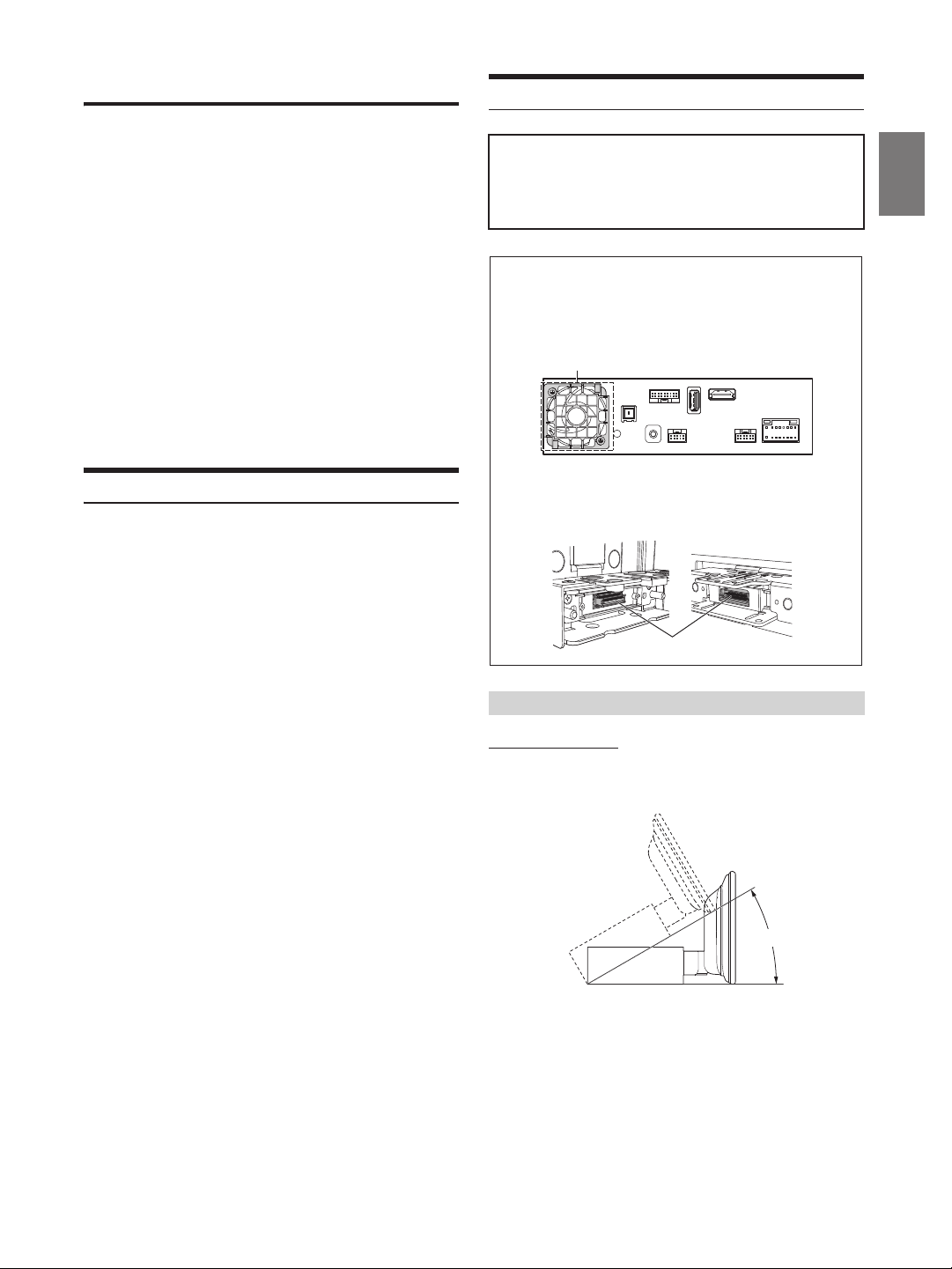
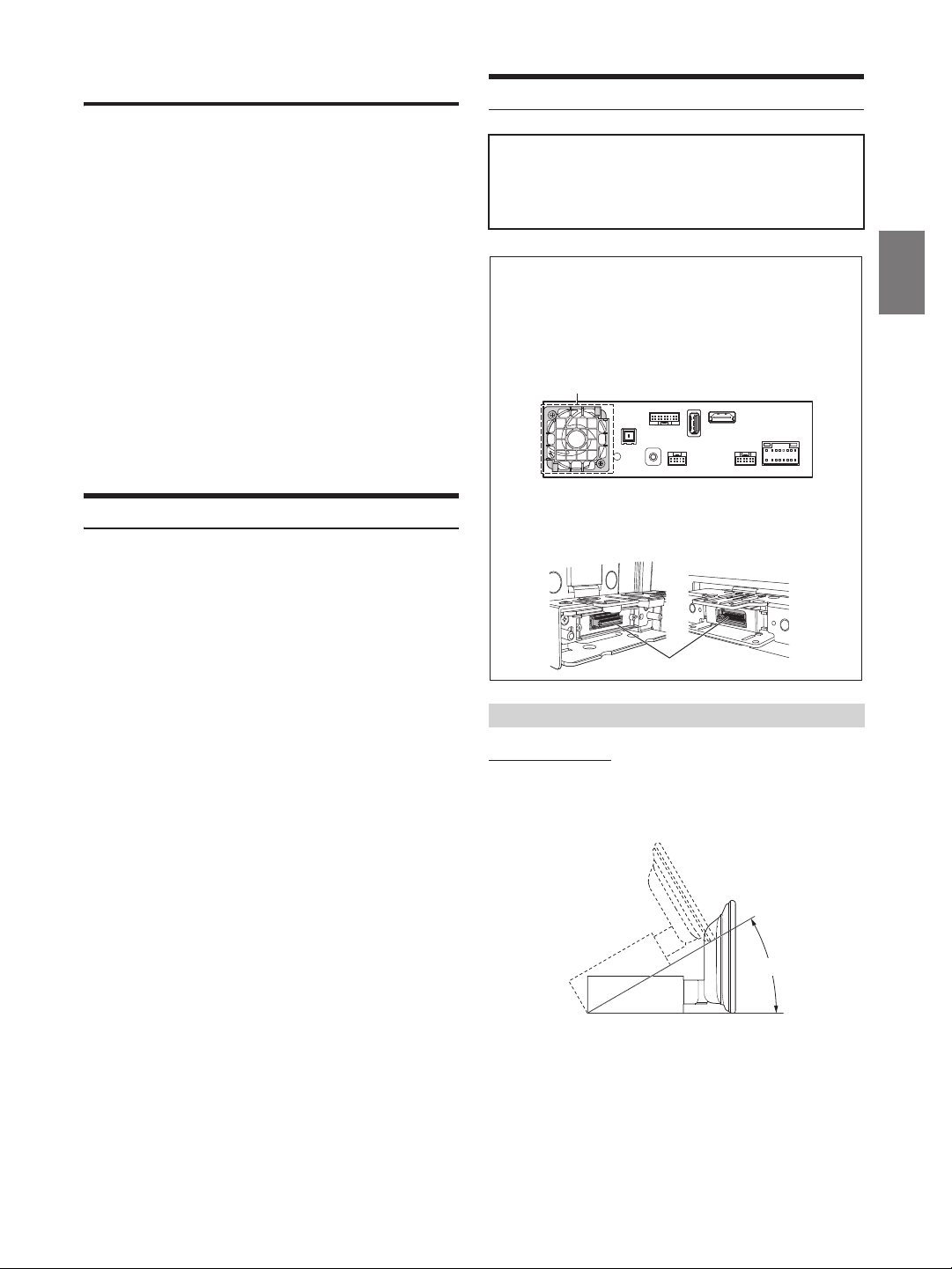
Caution
• Do not block the unit’s fan, thus preventing air
circulation. If blocked, heat will accumulate inside
the unit and may cause a fire.
<example>
Air ventilation hole
Rear of the Unit
• When installing the display unit and main unit, do not
touch the connectors with your hands.
<Display unit> <Main unit>
Connectors
Caution concerning the installation location
Angle of installation
Install at an angle between horizontal and 30°. Note that installing at
an angle outside of this range will result in a loss of performance and
possibly damage.
0 - 30°
3-EN
Page 6
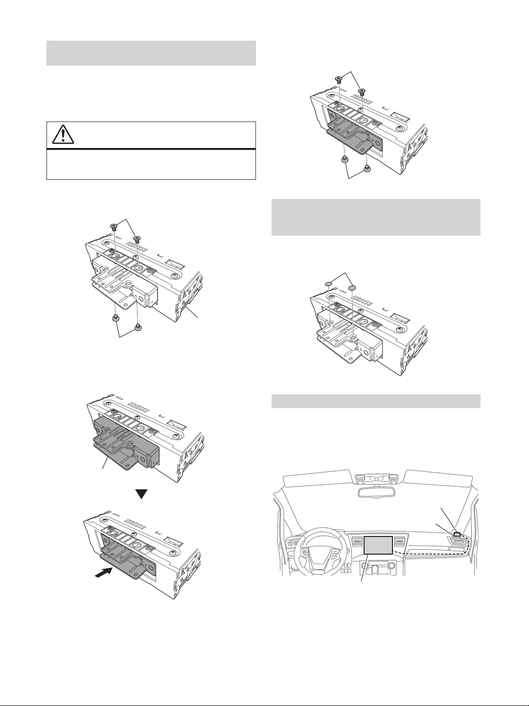
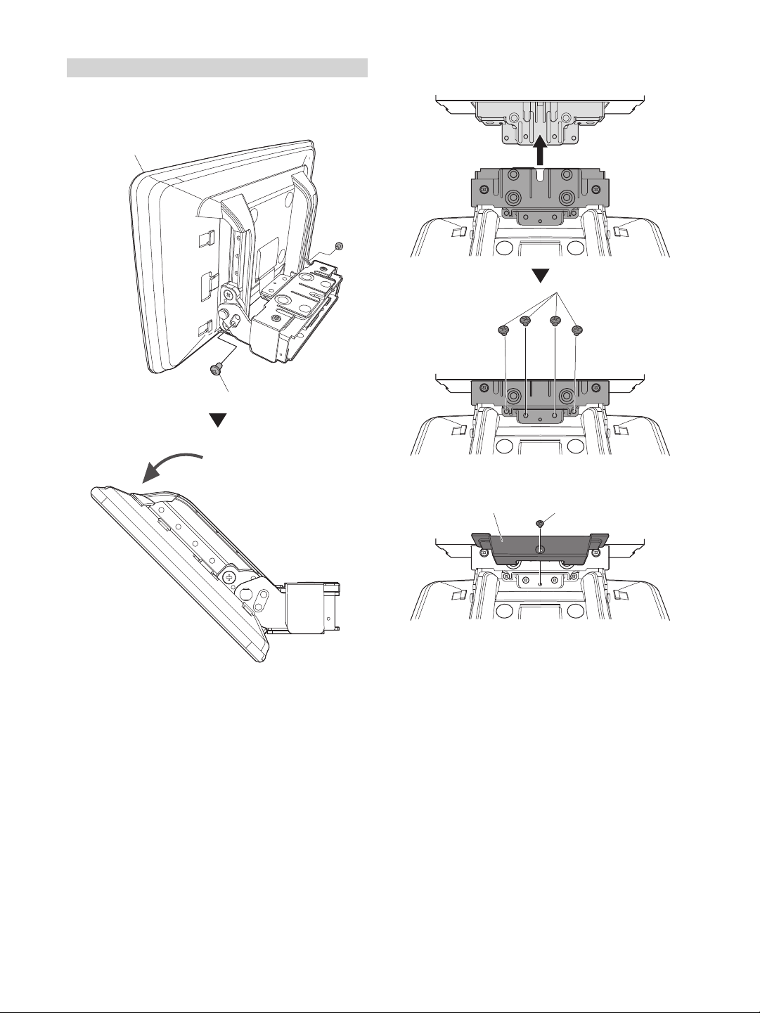
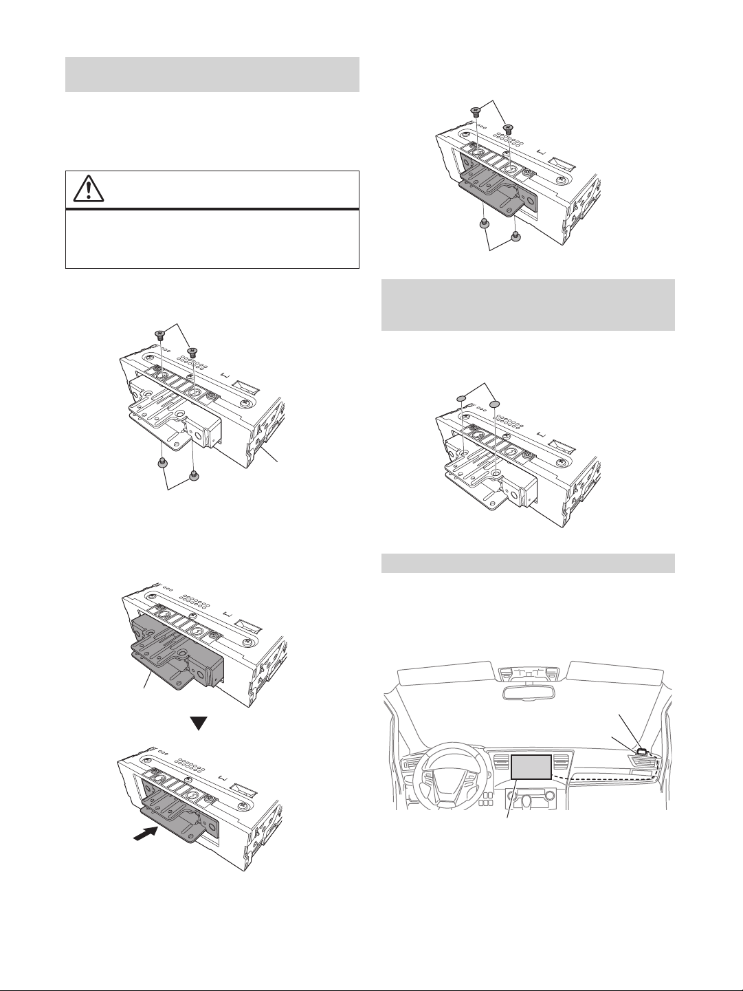
Adjust the front-back position of the Display
Flush head screw
Flush head screw
Main unit
Flush head screw
Flush head screw
Sheet cap
unit (Optional)
Depending on the vehicle, it may be necessary to adjust the frontback position of the Display unit when mounting it.
If front-back position adjustment is necessary, set the slider to the
back position before mounting the display unit to the vehicle.
[Default setting: forward position]
WARNING
MAGNETIC SCREWDRIVER REQUIRED TO
CAREFULLY REMOVE SCREWS.
1 Remove 4 flush head screws from the Top and Bottom of
the main unit.
3 Tightly fix the slider using the 4 screws that were
removed in Step 1.
Attach the Sheet cap (Only necessary when
the front-back position of the Display unit is in
the forward position)
Only attach the Sheet cap wh en the front-back position of the Display
unit is in the forward position.
2 Push the slider to the back position (To return the slider
to the forward position, pull it forward).
Slider
Mounting the GPS Antenna inside the vehicle
1 Clean the mounting location.
2 Put on the GPS Antenna mounting plate.
3 Mount the GPS Antenna.
GPS Antenna
Antenna mounting plate
This unit
• Do not mount the GPS Antenna inside the centre console.
- Mount the GPS Antenna on a flat plane of the dash board or rear
tray.
- Make sure the GPS Antenna is not covered (obstructed) by any
metallic surface or object.
4-EN
Page 7
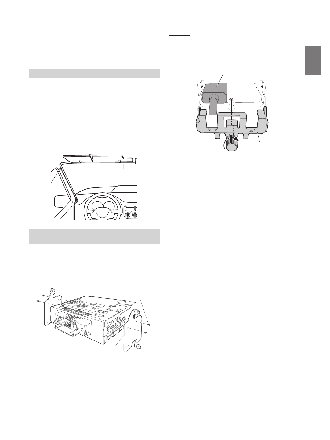
• If the GPS Antenna is mounted near the unit, the reception becomes
Microphone
Cable clamp
(Sold separately)
Original Mounting Bracket
Screws (M5×8)
(Included)
poor, and the location of your vehicle may not be displayed correctly.
- Mount the GPS Antenna far away enough from the unit.
- Bundle the GPS Antenna cable away from the rear of the unit.
• Some thermal reflection type or thermal absorption type glass may
interrupt high frequency waves. If reception is poor with the antenna
installed inside the car, try to mount the antenna outside the car.
Note on using HDMI Connection Cables (HDMI Cable not
included)
When using HDMI connection cables, secure the cables to the HDMI
Terminals with the supplied HDMI Bracket.
1) Slide the HDMI Bracket into the grooves (A).
2) Secure it with the screw (B).
Mounting the Microphone
For safe use, make sure of the following:
• Location is stable and firm.
• Does not interfere with safety equipment.
• Driver’s view and operations are not obstructed.
• Microphone is located where the driver’s voice can be easily
picked up (for example, on the sun visor).
When you speak into the microphone, you should not have to change
your driving posture. This may cause a distraction, taking your
attention away from safely driving your vehicle. Carefully consider
direction and distance while mounting the microphone. Confirm that
the driver’s voice can be easily picked up at the selected location.
Installation example using the Original
Mounting Bracket
HDMI Terminal
(A)
(A)
HDMI Bracket
(Included)
(B)
3 Mount the main unit in a car.
• Fix the cables carefully. Do not damage them by mounting them into
movable parts, such as the seat rail, or by locating them against sharp or
pointed edges.
4 Reattach the removed vehicle parts (panels, etc.) or
other aftermarket dash kit back onto the vehicle.
1 Mount the original mounting bracket to the main unit
using the supplied screws.
• If you do not have the original mounting bracket, mount the Double din
KIT* (provided with the side mounting bracket), etc. to the main unit.
* Sold separately.
2 Connect all other leads of the main unit according to
details described in the “Connections” (page 9).
5-EN
Page 8
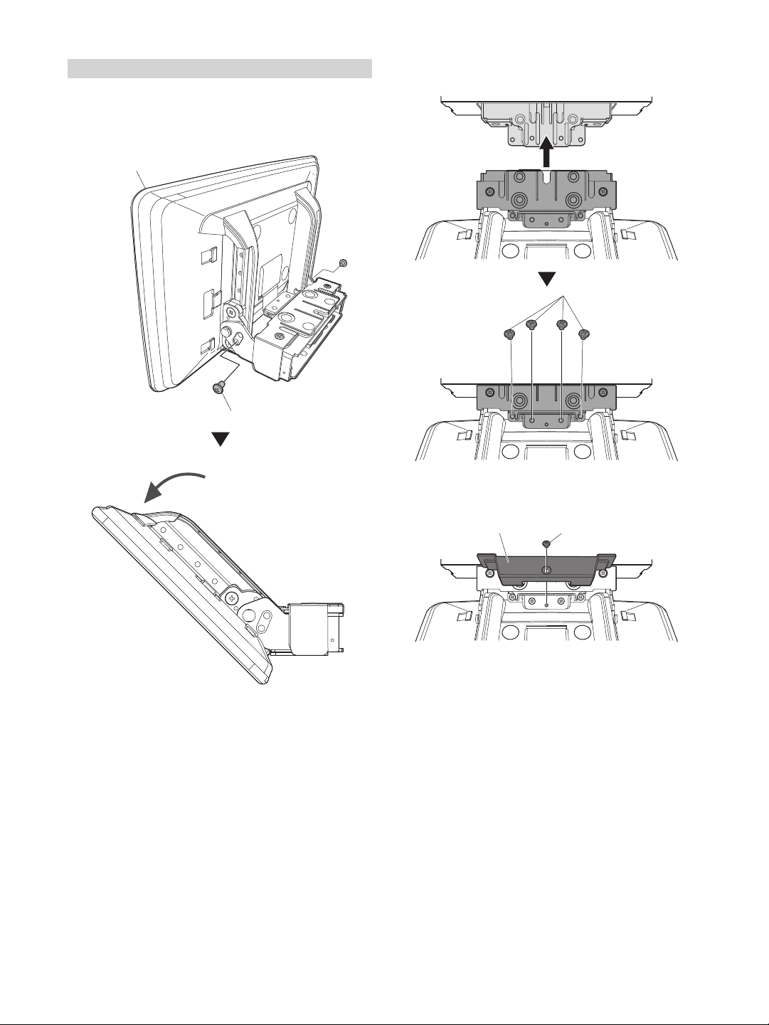
Install the display unit
POWER PLATE (Included)
Screw (M3×4) (Included)
1 Remove the 2 angle adjustment screws (M4×6) fixing the
left and right sides of the Display unit and pull the top of
the display forward.
Display unit
Angle adjustment screws (M4×6) (left and right)
2 Fix the Display unit to the slider of the main unit using 4
screws (M4×6).
Screw (M4×6) (Included)
• Vertical positioning screws may need to be removed earlier (See Step 4)
in order to manipulate the screen enough to install the POWER PLATE.
3 Mount the POWER PLATE using a screw (M3×4).
• If you do not attach the POWER PLATE, the display will not turn on.
Make sure to attach the POWER PLATE.
6-EN
Page 9
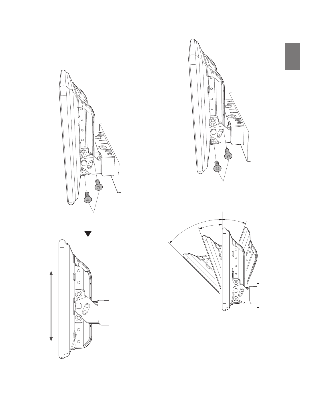
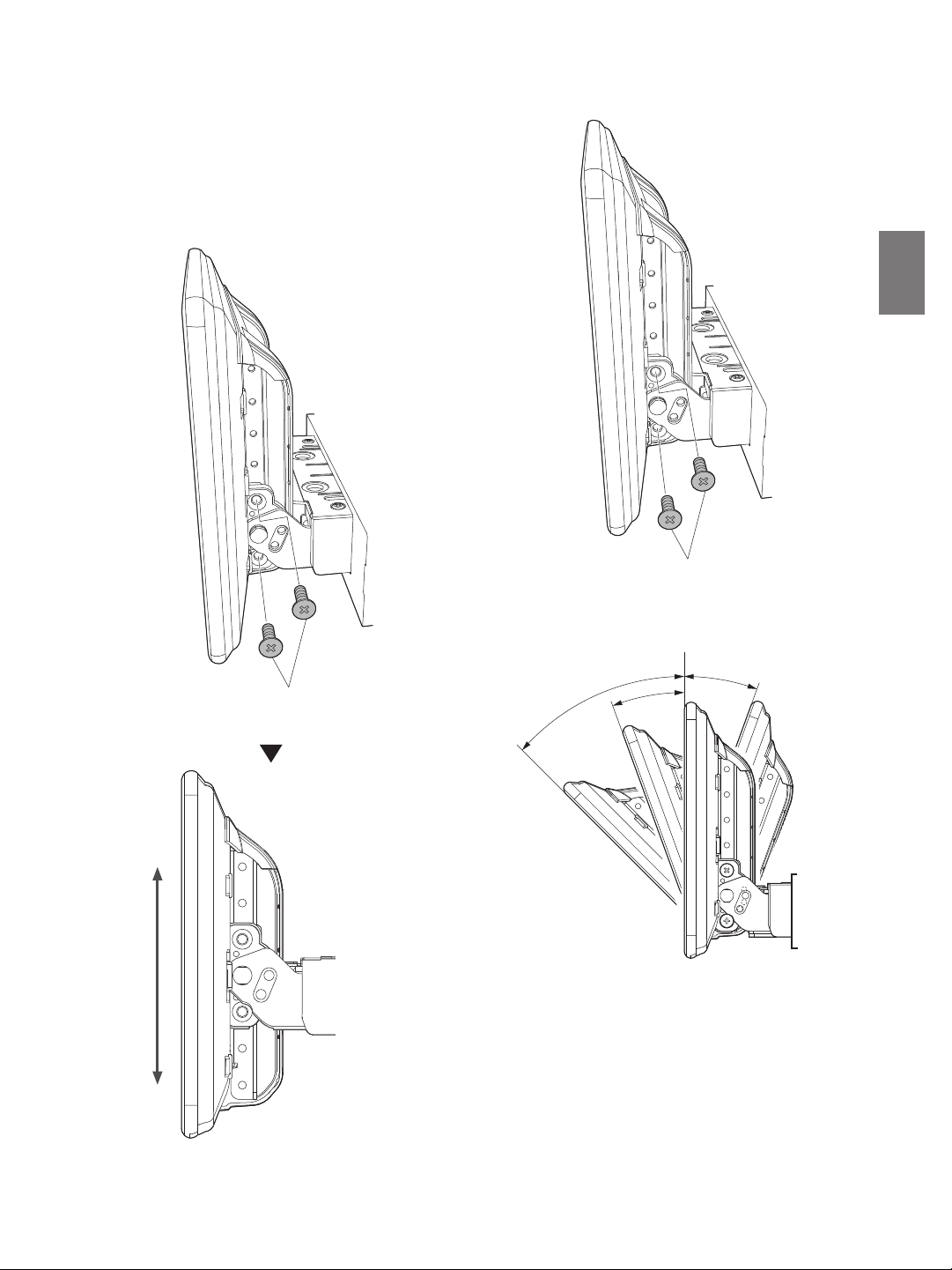
4 Adjust the mounting position of the display.
• The available adjustment positions of the Display differ depending on
the front-back/up-down/angle positions. Consult “Position Adjustment
and Mounting Dimensions of the Display” (page 18) for details.
1) Hold the Display up vertically, remove the 4 flush head
screws (M4×13) on the left and right sides for up-down
adjustment, and adjust the up-down position of the display.
2) After adjustment, tightly fix the display with the 4 Flush head
screws (M4×13) for up-down adjustment.
Flush head screw (M4×13)
(left and right)
Flush head screw (M4×13)
(left and right)
3) Adjust the angle of the display.
0°
45°
20°
-20°
7-EN
Page 10

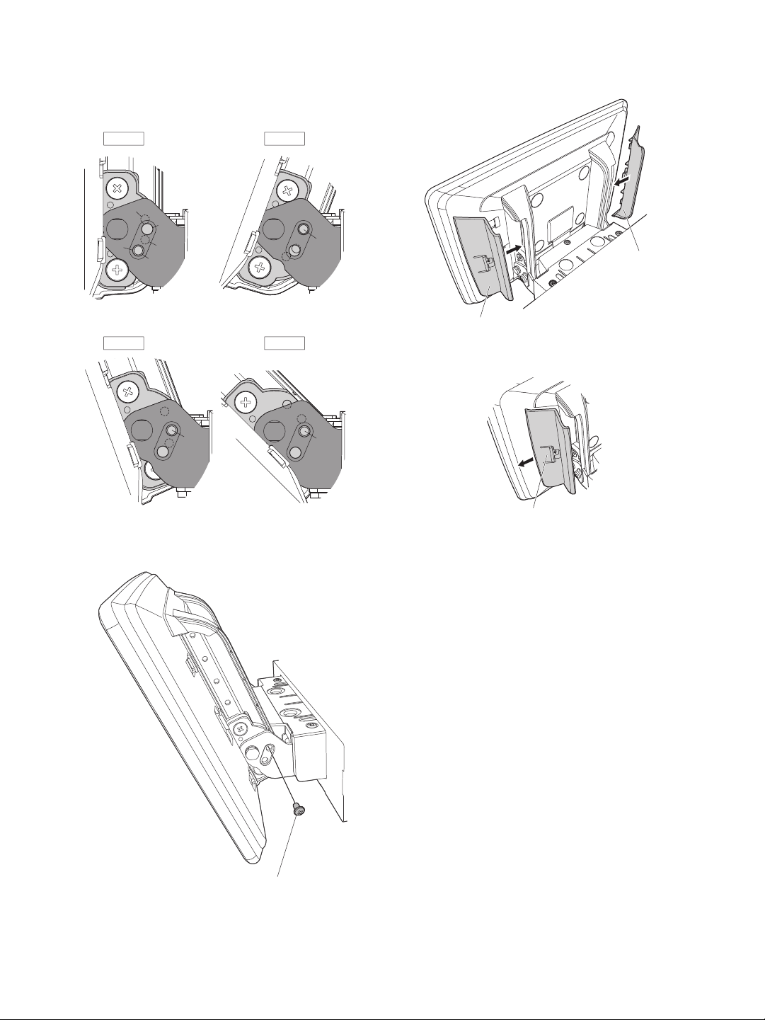
5 Attach Cover rear-L/R to the left and right sides of the
0° -20°
45°
20°
2-b
2-a
Refer to the illustration below to use the screw holes for angle
adjustmen t.
• Example:
To install the display at the angle of 20°, use the screw holes 2
and b.
2-c
a
b
c
2
1
Angle adjustment screws (M4×6)
(left and right)
display unit.
Cover rear L
(Included)
Cover rear R (Included)
• When removing Cover rear-L/R, push in the tab and slide it.
4) After adjustment, secure the display with the 2 angle
adjustment screws (M4×6) (left and right) that were removed
in Step 1 on page 6.
Tab
8-EN
Page 11
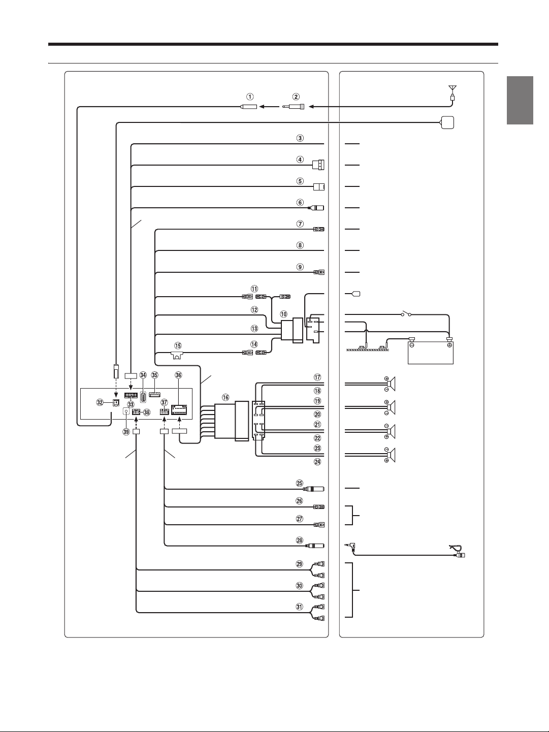
Connections
SPEED SENSOR
Antenna
(Green/White )
CAMERA
CONNE CT2 I/ F
AUX IN PUT
REMO
(Blue/White)
REVERSE
(Orange/White)
PAR KING BRA KE
(Yellow/Blue)
Power cable
(Green)
(Green/Black)
W.R EMOT E c abl e
STEERING REMOTE
SUBW
MIC IN
FRONT OUT
REAR OUT
ISO Antenna Plug
GPS Antenna (Included)
To the vehicle speed pulse line
To Front or Rear camera
To C AN Int er fa ce b ox
To AUX output device
To amplifier or equalizer
To plus side of the back lamp signal
lead of the car
To the parking brake signal lead
To power antenna
Rear Left
Front Left
Front Right
Rear Right
Speakers
To steering remote control interface
Microphone (Included)
To input terminal of amplifier when
adding an external amplifier
ACC
(Red)
GND
(Black)
P. AN T
(Blue)
BATT
(Yellow)
PRE OUT cable
(White)
(White/Black)
(Grey/Black )
(Grey)
(Violet/Black)
(Violet)
CAN I/F cable
Ignition key
Battery
To system unit
EXT REMO OUT
EXT REMO IN
9-EN
Page 12
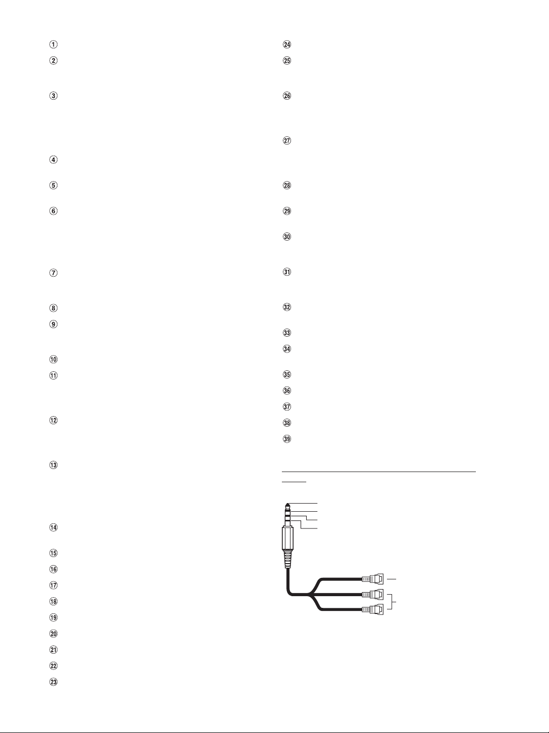
Radio Antenna Receptacle
Audio L (White)
Audio R (Red)
Ground
Video (Yellow)
(Yellow)
(Red)
(White)
Video input terminal
Audio input terminal (R, L)
ISO/JASO Antenna Adapter (sold separately)
ISO/JASO Antenna Adapter may be required, depending on the
vehicle.
Speed Sensor Lead (Green/White)
Improper connection of the speed pulse line may cause
important safety features of the vehicle to fail (such as the
brakes or air bags). Such failures may result in an accident and
loss of life. We strongly recommend that the installation be
performed by a trained, authorized Alpine dealer.
Direct CAMERA Input Connector
Use when the optional direct camera is connected.
CAN Interface Connector
To C AN I nterfa ce box
AUX Input Connector
Input lead for AUX video/audio signal.
• A separately sold AV/RCA interface cable (4-pole mini AV plug to
3-RCA) is required. For details on using an AV/RCA interface
cable (4-pole mini AV plug to 3-RCA), see “Usable AV/RCA
Interface Cable (4-pole mini AV plug to 3-RCA)” (page 10).
Remote Turn-On Lead (Blue/White)
Connect this lead to the remote turn-on lead of your amplifier or
signal processor.
Reverse Lead (Orange/White)
Parking Brake Lead (Yellow/Blue)
Connect this lead to the power supply side of parking brake
switch to transmit the parking brake status signals to the unit.
ISO Power Supply Connector
Switched Power Lead (Ignition) (Red)
Connect this lead to an open terminal on the vehicle’s fuse box
or another unused power source that provides (+) 12V only
when the ignition is turned on or in the accessory position.
Ground Lead (Black)
Connect this lead to a good chassis ground on the vehicle.
Make sure the connection is made to bare metal and is securely
fastened using the sheet metal screw provided.
Power Antenna Lead (Blue)
Connect this lead to the +B terminal of your power antenna, if
applicable.
• This lead should be used only for controlling the vehicle’s power
antenna. Do not use this lead to turn on an amplifier or a signal
processor, etc.
Battery Lead (Yellow)
Connect this lead to the positive (+) post of the vehicle’s battery.
Fuse Holder (15A)
ISO Connector (Speaker Output)
Left Rear (+) Speaker Output Lead (Green)
Left Rear (–) Speaker Output Lead (Green/Black)
Left Front (+) Speaker Output Lead (White)
Left Front (–) Speaker Output Lead (White/Black)
Right Front (–) Speaker Output Lead (Grey/Black)
Right Front (+) Speaker Output Lead (Grey)
Right Rear (–) Speaker Output Lead (Violet/Black)
10-EN
Right Rear (+) Speaker Output Lead (Violet)
Steering Remote Control Interface Connector
To steering remote control interface.
For details about connections, consult your nearest Alpine dealer.
EXT REMO OUT
To system unit.
For details about connections, confirm the instruction manual of
the system unit.
EXT REMO IN
To system unit.
For details about connections, confirm the instruction manual of
the system unit.
MIC Input Connector
To microphone (Included)
Subwoofer RCA Connectors
RED is right and WHITE is left.
Front Output RCA Connectors
Can be used as Front Output RCA Connectors. RED is right and
WHITE is left.
Rear Output RCA Connectors
Can be used as Rear Output RCA Connectors. RED is right and
WHITE is left.
GPS Antenna Receptacle
Connect to GPS antenna (Included).
CAN I/F Connector
USB Connector
To USB flash drive, iPod/iPhone or Android smartphone.
HDMI Input Connector
Power Supply Connector
W.REMOTE Connector
PRE OUT Connector
DAB Antenna Connector
To DAB Antenna (sold separately).
Usable AV/RCA Interface Cable (4-pole mini AV plug to
3-RCA)
Wiring convention of this system is as follows;
• Configuration commercially available 4-pole mini AV plugs is not
standardised.
Page 13
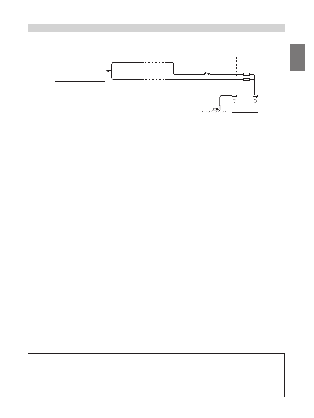
If an ACC power supply is not available
Connection Diagram of SPST Switch (sold separately)
ACC
INE-F904D
• If your vehicle has no ACC power supply, add an SPST (single-pole, single-throw) switch (sold separately) and fuse (sold separately).
• The diagram and the fuse amperage shown above are in the case when the unit is used individually.
• If the switched power (ignition) lead of the unit is connected directly to the positive (+) post of the vehicle’s battery, the unit draws some current (several
hundred milliamperes) even when its switch is placed in the OFF position, and the battery may be discharged.
(Red)
BATTERY
(Yellow)
SPST SW (Optional)
FUSE (5A)
(Opti onal)
FUSE (20A)
(Optio nal)
Battery
To prevent external noise from entering the audio system.
• Locate the unit and route the leads at least 10 cm away from the car harness.
• Keep the battery power leads as far away from other leads as possible.
• Connect the ground lead securely to a bare metal spot (remove any paint, dirt or grease if necessary) of the car chassis.
• If you add an optional noise suppressor, connect it as far away from the unit as possible. Your Alpine dealer carries various noise
suppressors, contact them for further information.
• Your Alpine dealer knows best about noise prevention measures so consult your dealer for further information.
11-EN
Page 14
System Example
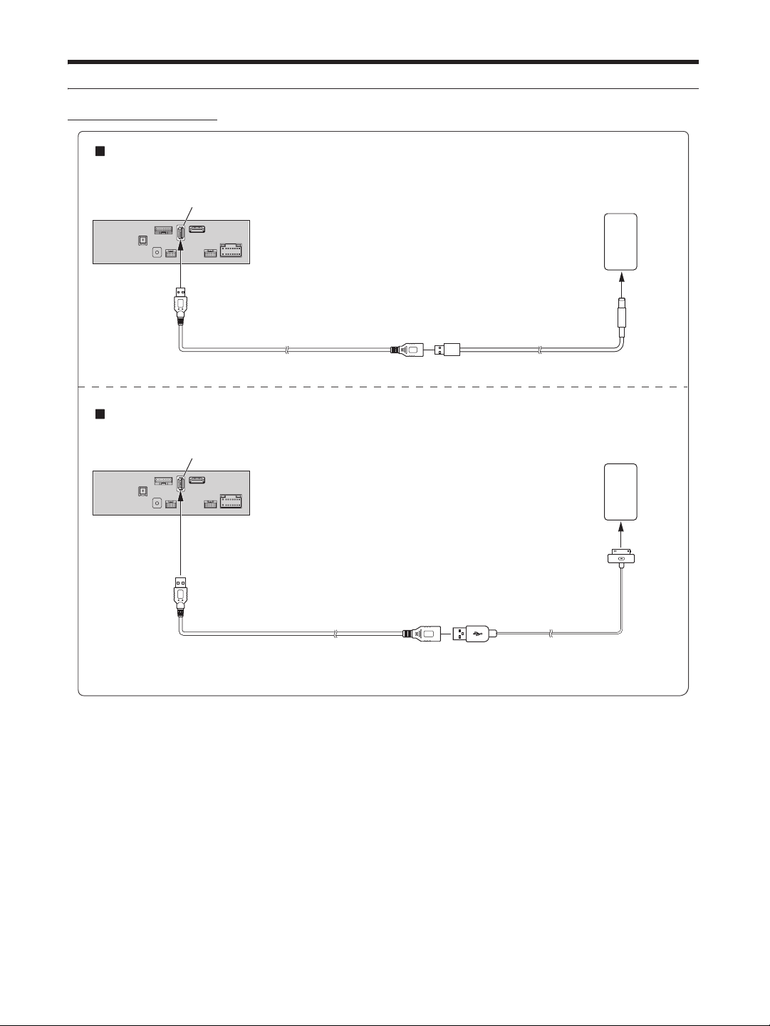
Connection of an iPod/iPhone
When connecting to an iPod/iPhone with a Lightning connector
USB connector
USB extension ca ble (Included)
When connecting to iPhone 4S
USB connector
iPod/iPhone with a Lightning
connector (sold separately)
Lightning to USB Cable
KCU-471i (sold separately)
iPhone 4S
(sold separately)
USB extension cable (In cluded)
• Do not leave an iPod/iPhone in a vehicle for a long time. Heat and humidity may damage the iPod/iPhone, and you may not be able to play it again.
Included with iPhone 4S
12-EN
Page 15
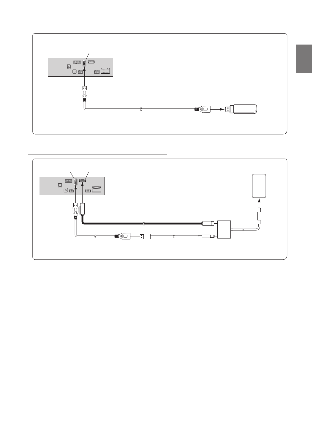
Connection of a Flash Drive
USB connector
USB extension ca ble (Included)
• Do not leave a flash drive in a vehicle for a long time. Heat and humidity may damage the flash drive.
Connection of an HDMI Device (iPhone with a Lightning connector)
USB Flash Drive ( sold separately)
USB connector
HDMI input connecto r*
USB extension ca ble
(Included)
HDMI connection ki t KCU-610HD (sold separately)
Lightning to USB Cable
KCU-471i (sold separately)
Lightning Digital AV Adapter
(Apple Inc., products)
(sold separately)
iPhone with a Lightning
connector (sold separately)
* When connecting an HDMI connection cable, be sure to secure it using the supplied HDMI Bracket. For details on how to secure it, see “Note on using
HDMI Connection Cables (HDMI Cable not included)” (page 5).
• Set the HDMI Setup to “HDMI.” For details, refer to “HDMI Setup” in the OWNER’S MANUAL (CD-ROM).
13-EN
Page 16
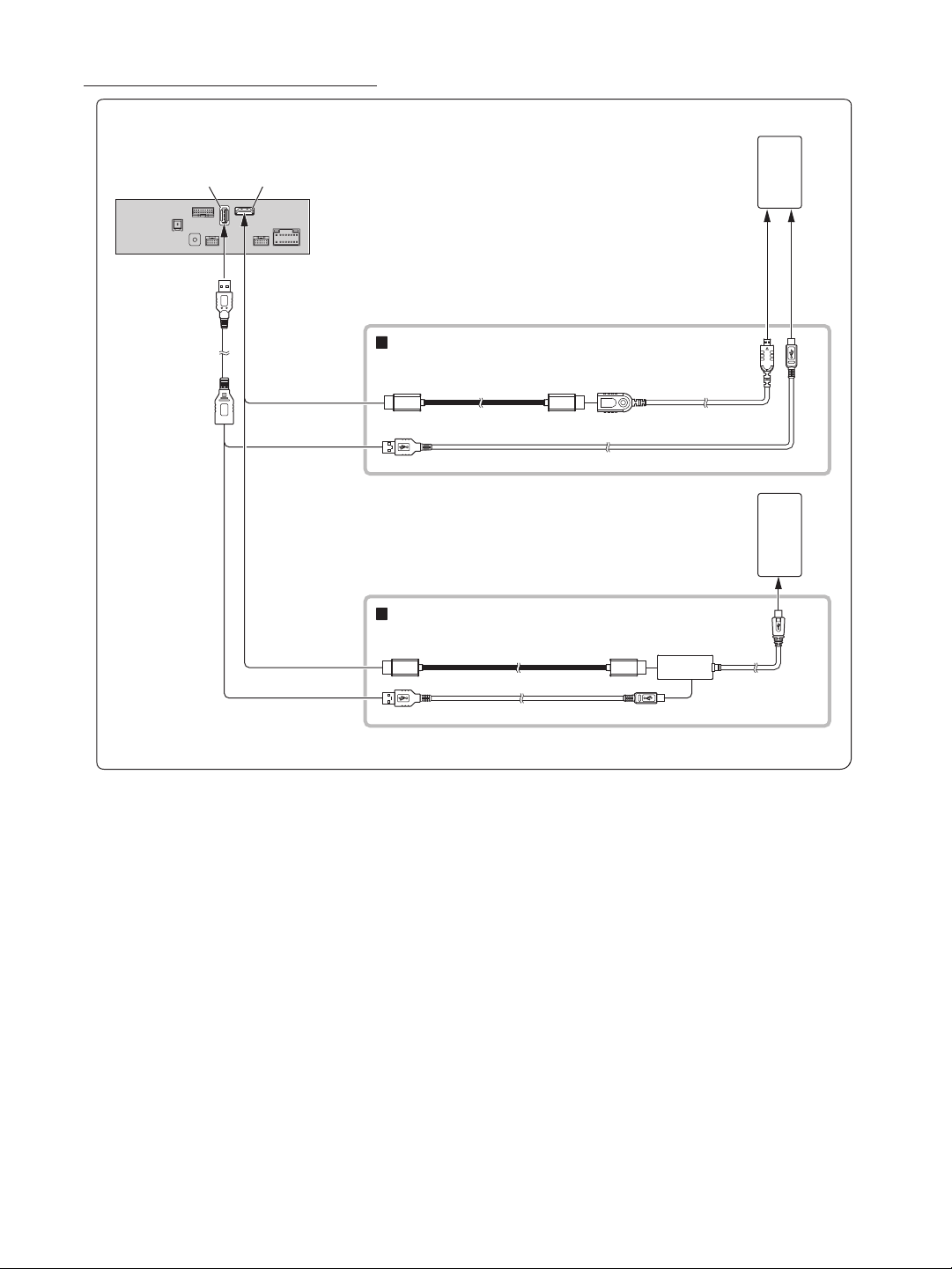
Connection of an HDMI Device (Android device)
USB connector
HDMI input connector*
Android device with
HDMI connector
(sold separately)
USB extension cable
(Included)
HDMI connection kit KCU-610HD (sold separately)
HDMI connection cable
Micro USB conversion cable
HDMI Type-D
conversion adapter
Android device with
MHL connector (sold
separately)
MHL connection kit KCU-610MH (sold separately)
HDMI connection cable
MHL conversion adapter
Micro USB conversion cable
• A connection kit or adapter kit suitable for the type of terminal on the connecting device is required.
• Set the HDMI Setup to “HDMI.” For details, refer to “HDMI Setup” in the OWNER’S MANUAL (CD-ROM).
* When connecting an HDMI connection cable, be sure to secure it using the supplied HDMI Bracket. For details on how to secure it, see “Note on using
HDMI Connection Cables (HDMI Cable not included)” (page 5).
14-EN
Page 17
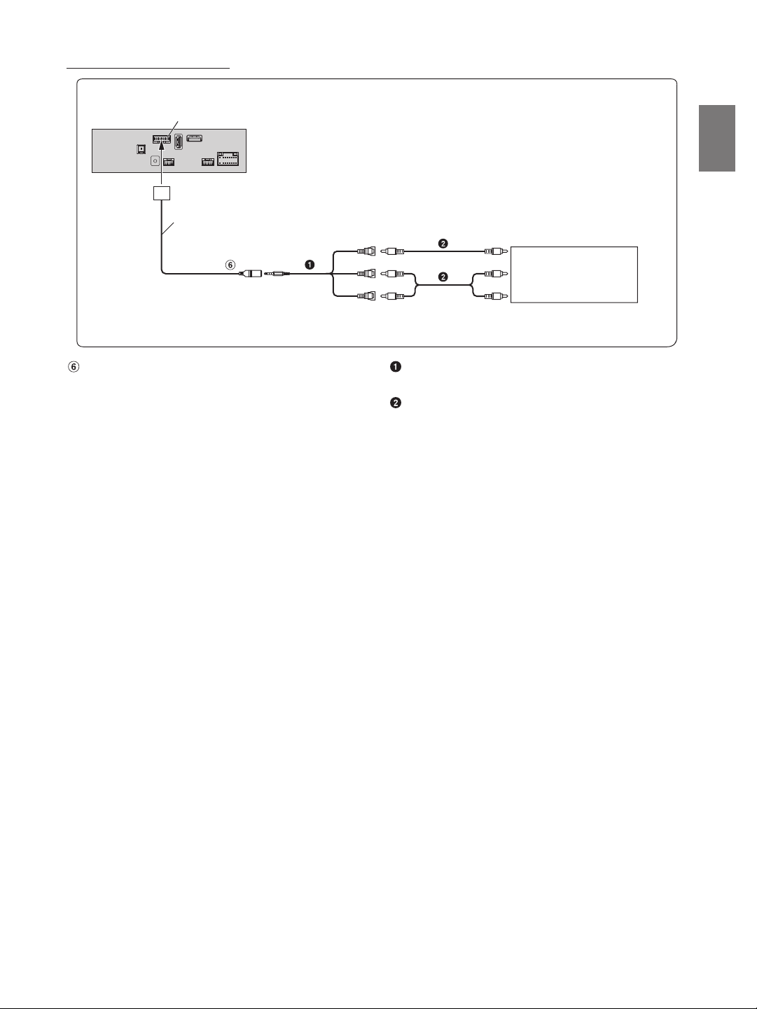
Connection of an External Device
CAN I/F connector
CAN I/F cable
AUX IN PUT
(Yellow)
(Red)
(White)
To Video Output terminal
External Device
(sold se parately)
To Audio Outpu t terminal
AUX Input Connector AV/RCA Interface Cable (4-pole mini AV plug to 3-RCA)
(sold separately)
RCA Extension Cable (sold separately)
• You can change the name of an external device. For details, refer to “Setting the Auxiliary (AUX) Name” in the OWNER’S MANUAL (CD-ROM).
• For details on using an AV/RCA interface cable (4-pole mini AV plug to 3-RCA), see “Usable AV/RCA Interface Cable (4-pole mini AV plug to 3-RCA)”
(page 10).
15-EN
Page 18
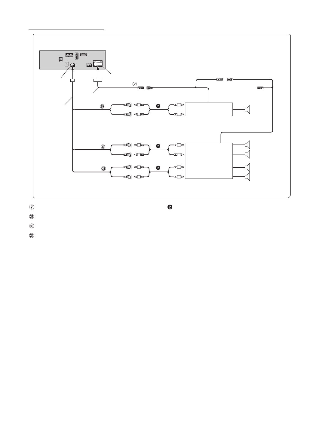
Connection of an External Amplifier
PRE OUT connect or
Power cable
PRE OUT cable
SUBW
FRONT OUT
REAR OUT
Remote Turn-On Lead (Blue/White)
Subwoofer RCA Connectors
Front Output RCA Connectors
Rear Output RCA Connectors
Power Supply connector
REMO
(Blue/White)
(Red)
(White)
(Red)
(White)
(Red)
(White)
REMOTE ON
(Blue/White)
Amplifier for subwoofer
(sold separately)
To subwoofer input terminal
To front input terminal
Amplifier 4 ch
(sold separately)
To rear input terminal
RCA Extension Cable (sold separately)
REMOTE ON
(Blue/White)
Subwoofer
Front speaker
Rear speaker
16-EN
Page 19
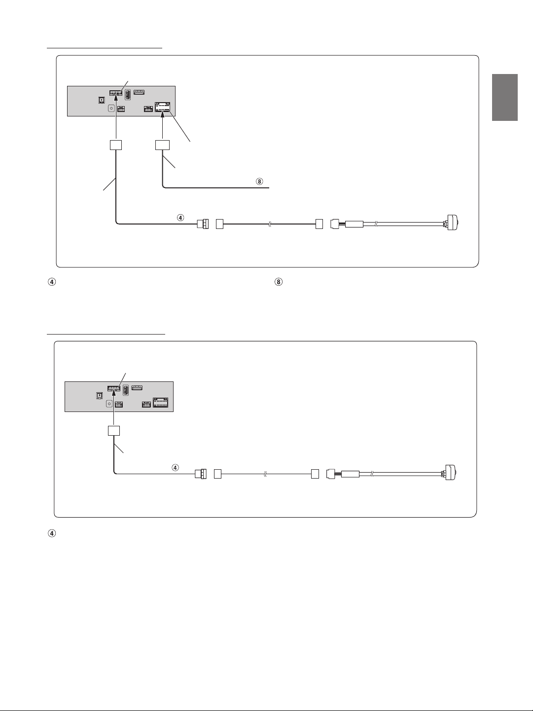
Connection of a Rearview camera
CAN I/F connector
Power Supply connector
Power cable
CAN I/F cable
CAMERA
Reverse
(Orange/White)
Camera extension cable
(included with direct rearview camera)
Connect to the plus side of the car’s reverse lamp.
HCE-C127D/HCE-C157D/HCE- C252RD
(sold separately)
Direct CAMERA Input Connector Reverse Lead (Orange/White)
• Set the Camera Select to “Rear.” For details, refer to “Setting the Camera Input” in the OWNER’S MANUAL (CD-ROM).
Connection of a Frontview camera
CAN I/F connector
CAN I/F cable
CAMERA
Camera extension c able
(included with direct frontview camera)
HCE-C257FD/HCE-C212FD
(sold separately)
Direct CAMERA Input Connector
• Set the Camera Select to “Front.” For details, refer to “Setting the Camera Input” in the OWNER’S MANUAL (CD-ROM).
17-EN
Page 20
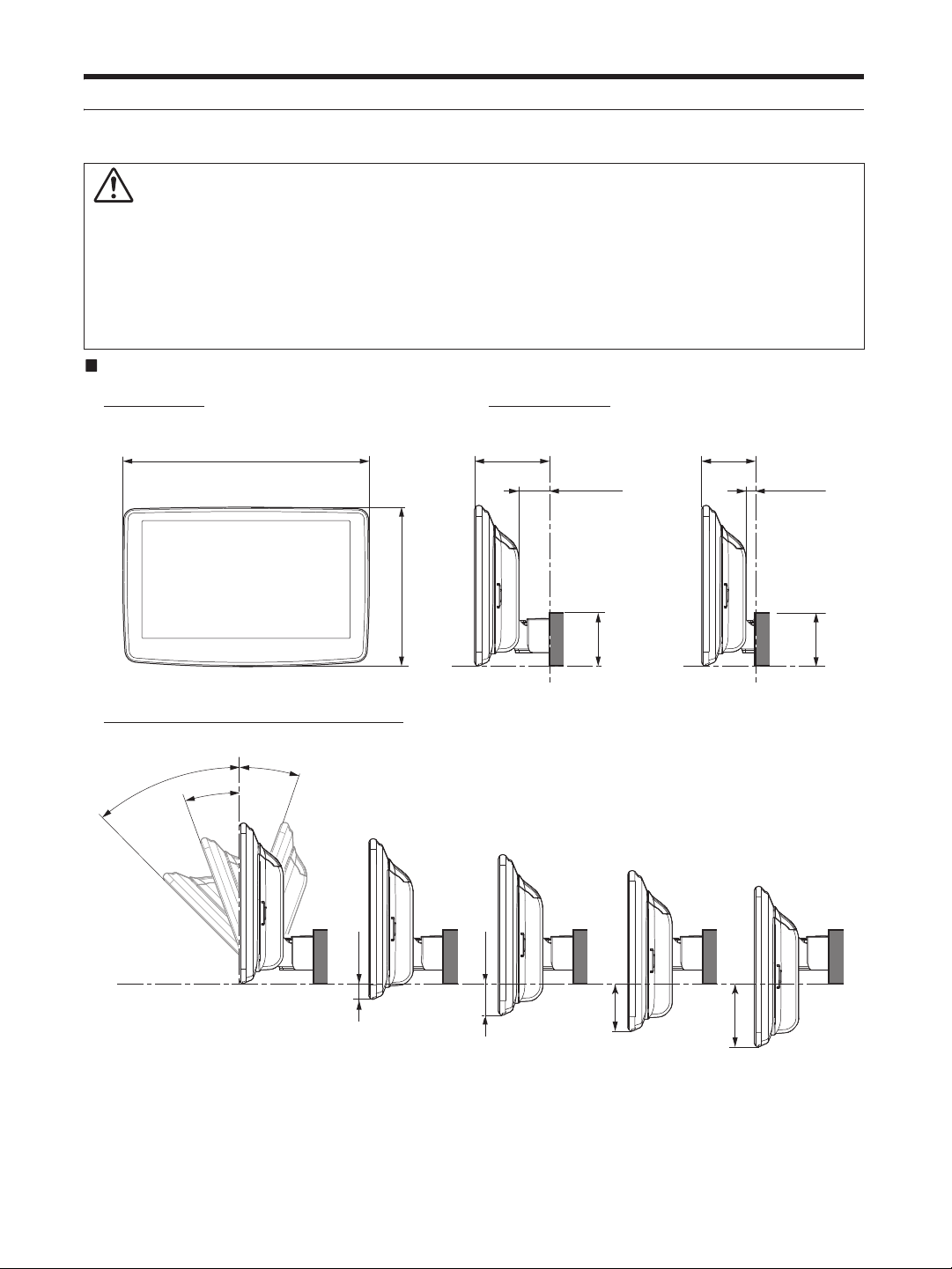
Position Adjustment and Mounting Dimensions of the Display
<Forward position>
<Back posi tion>
235.2 mm (MAX)
70 mm
28 mm
50 mm
8 mm
152.2 mm (MAX)
50 mm
50 mm
0
The mounting position of this unit’s Display can be adjusted (front-back/up-down/angle). When mounting the Display, confirm the mounting
position and mounting dimensions so that it does not obstruct your field of vision or impair driving.
WARNING
• In the following cases, the display cannot be mounted.
- It impairs operation of the steering wheel or various levers (gearshift, windshield wiper switch, turn signal switch, etc.)
- It impairs operation of the airbag
- It significantly impairs operation of the hazard switch
- It impairs identification or operation of any other control switches
- It impairs confirmation of gauges or warning indicators
- It interferes with vehicle equipment (switches, panels, etc.)
* Depending on the vehicle, the glove compartment or cup holders may become inaccessible, or air conditioner ventilation ducts may be covered.
Display mounting dimensions and adjustable positions
Display unit size
Adjustable Display angle and up-down position
0°
45°
20°
-20°
Front-back position
-15 mm
* Depending on the up-down position of the forward and back positions, there are certain positions in which the angle cannot be adjusted.
Consult “Mounting Dimensions for Angle Adjustment of the Display” (page 19) for details.
18-EN
-30 mm
-45 mm
-60 mm
Page 21

Mounting Dimensions for Angle Adjustment of the Display
A’
A
B
B’
<Front-back position: forward> :mm
Angle: 45° Angle: 20° Angle: -20°
A’
A
B
B’
B
A’
A
B’
AA’BB’AA’BB’AA’BB’
0 100.8 142.4 -5.3 36.2 134.2 106.7 -5.3 53.4 100.2 80 9.3 5.6
-15 mm
-30 mm
-45 mm
-60 mm
120.1 101.6 -19.4 48.3 86.1 85.1 -4.9 10.7
106 96.4 -33.5 43.1 72 90.3 -18.9 15.8
91.9 91.3 -47.6 38 57.9 95.4 -33 21
77.8 86.2 -61.7 32.9 43.8 100.5 -47.1 26.1
<Front-back position: back> :mm
Angle: 45° Angle: 20° Angle: -20°
A’
A’
B’
A
B
B’
A
A
B
B’
B
A’
AA’BB’AA’BB’AA’BB’
0 100.8 122.4 -5.3 16.2 134.2 86.7 -5.3 33.4 100.2 60 9.3 -14.4
-15 mm
-30 mm
-45 mm
-60 mm
120.1 81.6 -19.4 28.3 86.1 65.1 -4.9 -9.3
72 70.3 -18.9 -4.2
57.9 75.4 -33 1
43.8 80.5 -47.1 6.1
* The parts in the table cannot be adjusted.
19-EN
Page 22

Page 23

Inhalt
WARNUNG .................................................... 2
VORSICHT ..................................................... 2
Vorsichtsmaßnahmen ................................. 3
Lieferumfang ..........................................................3
Einbau .....................................................................3
Vorsichtshinweise zur Installation .................. 3
Passen Sie den Befestigungsabstand für das
Display an (optional) ..................................... 4
Bringen Sie die Klebepunkte an (nur
erforderlich bei erhöhtem
Befestigungsabstand des Displays) ..............4
Montieren der GPS-Antenne im Fahrzeug .... 4
Einbau des Mikrofons ....................................... 5
Installationsbeispiel mit der
Originalmontagehalterung ........................... 5
Bringen Sie das Display an ...............................6
Anschlüsse .............................................................. 9
Bei Fahrzeugen ohne ACC-
Spannungsversorgung .................................11
Systembeispiel ......................................................12
Positionsanpassung und Montageabmessungen
des Displays ......................................................18
DEUTSCH
1-DE
Page 24
WARNUNG
Dieses Symbol weist auf wichtige Anweisungen hin.
Bei Nichtbeachtung besteht die Gefahr von
schweren Verletzungen oder Todesfällen.
GERÄT NICHT ÖFFNEN.
Andernfalls besteht Unfallgefahr, Feuergefahr oder die Gefahr eines
elektrischen Schlages.
KLEINE GEGENSTÄNDE WIE SCHRAUBEN VON KINDERN FERNHALTEN.
Werden solche Gegenstände verschluckt, besteht die Gefahr
schwerwiegender Verletzungen. Suchen Sie unverzüglich einen
Arzt auf, wenn ein Kind einen solchen Gegenstand verschluckt.
SICHERUNGEN IMME R DURCH SOLCHE MIT DER RICHTIG EN AMPEREZAHL
ERSETZEN.
Andernfalls besteht Feuergefahr oder die Gefahr eines elektrischen
Schlages.
LÜFTUNGSÖFFNUNGEN UND KÜHLKÖRPER NICH T ABDECKEN.
Andernfalls kann es zu einem Wärmestau im Gerät kommen, und
es besteht Feuergefahr.
DAS GERÄT NUR AN EIN 12-V-BORDNETZ IN EINEM FAHRZEUG
ANSCHLIESSEN.
Andernfalls besteht Feuergefahr, die Gefahr eines elektrischen
Schlages oder anderer Verletzungen.
AUF KORREKTE ANSCHLÜSSE ACHTEN.
Bei fehlerhaften Anschlüssen besteht Feuergefahr, und es kann zu
Schäden am Gerät kommen.
NUR IN FAHRZEUGEN MIT 12-VOLT-BORDNETZ UND NEGATIVER MASSE
VERWENDEN.
Fragen Sie im Zweifelsfall Ihren Händler. Andernfalls besteht
Feuergefahr usw.
VOR DEM ANSCHLUSS DAS KA BEL VOM MINUSPOL DER BATTERIE
ABKLEMMEN.
Andernfalls besteht die Gefahr eines elektrischen Schlages oder
Verletzungsgefahr durch einen Kurzschluss.
DAFÜR SORGEN, DASS SICH DIE KABEL NICHT IN GEGENSTÄNDEN IN DER
NÄHE VERFANGEN.
Verlegen Sie die Kabel wie im Handbuch beschrieben, damit sie
beim Fahren nicht hinderlich sind. Kabel, die sich im Lenkrad, im
Schalthebel, im Bremspedal usw. verfangen, können zu äußerst
gefährlichen Situationen führen.
ELEKTRISCHE KABEL NICHT SPLEISSEN.
Kabel dürfen nicht abisoliert werden, um andere Geräte mit Strom
zu versorgen. Andernfalls wird die Strombelastbarkeit des Kabels
überschritten, und es besteht Feuergefahr oder die Gefahr eines
elektrischen Schlages.
BEIM BOHREN VON LÖCHERN LEITUNGEN UND KABEL NIC HT BESCHÄDIGEN.
Wenn Sie beim Einbauen Löcher in das Fahrzeugchassis bohren,
achten Sie unbedingt darauf, die Kraftstoffleitungen und andere
Leitungen, den Benzintank und elektrische Kabel nicht zu berühren,
zu beschädigen oder zu blockieren. Andernfalls besteht Feuergefahr.
BOLZEN UND MUTTERN DER BREMSANLAGE NICHT ALS MASSEPUNKTE
VERWENDEN.
Verwenden Sie für Einbau oder Masseanschluß NIEMALS Bolzen
oder Muttern der Brems- bzw. Lenkanlage oder eines anderen
sicherheitsrelevanten Systems oder des Benzintanks. Andernfalls
besteht die Gefahr, dass Sie die Kontrolle über das Fahrzeug
verlieren oder ein Feuer ausbricht.
DAS GERÄT NICHT AN EINER STELLE EINBAUEN, AN DER ES BEIM FAHREN
HINDERLICH SEIN KÖNNTE, WEIL ES Z. B. DAS LENKRAD ODER DEN
SCHALTHEBEL BLOCKIERT.
Andernfalls ist möglicherweise keine freie Sicht nach vorne
gegeben, oder die Bewegungen des Fahrers sind so eingeschränkt,
dass Unfallgefahr besteht.
DIE DISPLAYEINHEIT NICHT IN DER NÄHE DES BEIFAHRER-AIRBAGS
EINBAUEN.
Bei unsachgemäßem Einbau kann der Airbag versagen oder beim
Aufblähen die Displayeinheit in die Fahrgastzelle schleudern und
Verletzungen verursachen.
VORSICHT
Dieses Symbol weist auf wichtige Anweisungen hin.
Bei Nichtbeachtung besteht die Gefahr von
Verletzungen bzw. Sachschäden.
VERKABELUNG UND EINBAU VON FACHPERSONAL AUSFÜHREN LASSEN.
Die Verkabelung und der Einbau dieses Geräts erfordern
technisches Geschick und Erfahrung. Zu Ihrer eigenen Sicherheit
sollten Sie Verkabelung und Einbau dem Händler überlassen, bei
dem Sie das Gerät erworben haben.
NUR DAS VORGESCHRIEBENE ZUBEHÖR VERWENDEN UND DIESES
SICHER EINBAUEN.
Verwenden Sie ausschließlich das vorgeschriebene Zubehör.
Andernfalls wird das Gerät möglicherweise beschädigt, oder es lässt
sich nicht sicher einbauen. Wenn sich Teile lösen, stellen diese eine
Gefahrenquelle dar, und es kann zu Betriebsstörungen kommen.
DIE KABEL SO VERLEGEN, DASS SIE NICHT GEKNICKT ODER DURCH
SCHARFE KANTEN GEQUETSCHT WERDEN.
Verlegen Sie die Kabel so, dass sie sich nicht in beweglichen Teilen
wie den Sitzschienen verfangen oder an scharfen Kanten oder spitzen
Ecken beschädigt werden können. So verhindern Sie eine
Beschädigung der Kabel. Wenn Sie ein Kabel durch eine Bohrung in
einer Metallplatte führen, schützen Sie die Kabelisolierung mit einer
Gummitülle vor Beschädigung durch die Metallkanten der Bohrung.
DAS GERÄT NICHT AN STELLEN EINBAUEN, AN DENEN ES HOHER
FEUCHTIGKEIT ODER STAUB AUSGESETZT IST.
Bauen Sie das Gerät so ein, dass es vor hoher Feuchtigkeit und
Staub geschützt ist. Wenn Feuchtigkeit oder Staub in das Gerät
gelangen, kann es zu Betriebsstörungen kommen.
2-DE
Page 25
Vorsichtsmaßnahmen
• Trennen Sie unbedingt das Kabel vom (–) Batteriepol, bevor Sie
das Gerät installieren. Dadurch vermeiden Sie die Gefahr einer
Beschädigung des Geräts, falls es zu einem Kurzschluss kommt.
• Auf korrekten Anschluss der farbcodierten Kabel achten!
Anschlussfehler können Betriebsstörungen des Geräts bzw.
Fahrzeugs zur Folge haben.
• Beim Anschließen an das Bordnetz des Fahrzeugs unbedingt die
werkseitig eingebauten Komponenten (z. B. Bordrechner)
beachten. Keinesfalls die Stromversorgung für das Gerät an diesen
Komponenten abgreifen. Beim Anschluss des Geräts im
Sicherungskasten darauf achten, dass die Sicherung des gewählten
Stromkreises die für das Gerät vorgeschriebene Amperezahl
aufweist. Wenden Sie sich im Zweifelsfall an Ihren Alpine-Händler.
• Das Gerät wird über RCA-Buchsen an andere Komponenten (z.
B. Verstärker) angeschlossen. Zum Anschließen eines anderen
Geräts werden unter Umständen Steckeradapter benötigt. Lassen
Sie sich diesbezüglich von Ihrem autorisierten Alpine-Händler
beraten.
• Achten Sie darauf, die Lautsprecherkabel (–) an den
Lautsprecheranschluss (–) anzuschließen. Verbinden Sie auf
keinen Fall Lautsprecherkabel für den linken und den rechten
Kanal miteinander oder mit der Fahrzeugkarosserie.
Lieferumfang
Hauptgerät.........................................................................................................1
Display .................................................................................................................1
Bedienungsanleitung............................................................................1 Satz
<Kabel>
Stromversorgungskabel................................................................................1
GPS-Antenne..................................................................................................... 1
Antennenmontageplatte..............................................................................1
Kabelklemme für Antenne ..................................................................1 Satz
USB-Anschlusskabel ....................................................................................... 1
PRE OUT-Kabel..................................................................................................1
Mikrofon..............................................................................................................1
CAN I/F-Kabel .................................................................................................... 1
W.REMOTE-Kabel ............................................................................................. 1
<Hauptgerät-Montageteile>
HDMI-Halterung...............................................................................................1
Senkschraube (M5×8) .................................................................................... 4
Schraube (M5×8) ............................................................................................. 4
<Display-Montageteile>
SICHERHEITSABDECKUNG............................................................................ 1
Abdeckung hinten L .......................................................................................1
Abdeckung vorne R ........................................................................................ 1
Senkschraube (M4×13)...........................................................................2(
Schraube (M4×6) ......................................................................................7(
Schraube (M3×4) ......................................................................................2(
Klebepunkte ...............................................................................................4(*4)
• Die Teile der Montageteile des Displays mit * enthalten
Ersatzteile im Falle eines Verlusts. Bewahren Sie diese sicher auf.
*1 Anzahl der Ersatzteile für die Höhenverstellung des Displays.
*2 Enthält 3 Ersatzteile zum Befestigen und Einstellen des Winkels
des Displays.
*3 Enthält ein 1 Ersatzteil zum Befestigen der Mitte der Abdeckung.
*4 Enthält 2 Ersatzteile zum Blockieren des Anzeigebildschirms.
*1)
*2)
*3)
Einbau
Montage
Sehen Sie sich vor der Montage den Abschnitt
„Positionsanpassung und Montageabmessungen des
Displays“ (Seite 18) an, damit dieses Gerät nach der
Montage nicht Ihre Sicht oder das Fahren behindert.
Vorsicht
• Achten Sie auf ungehinderte Luftzirkulation im Bereich des
Ventilators. Falls die Belüftungsöffnungen verdeckt oder
verschlossen werden, kommt es zu Hitzestau im Gerät und
Brandgefahr.
<Beispiel>
Belüftungsöffnung
Rückseite des Ge rät s
• Berühren Sie bei der Installation des Displays und
Hauptgeräts nicht die Anschlüsse.
<Display>
Anschlüsse
Vorsichtshinweise zur Installation
Installationswinkel
Die Installation sollte in einem Winkel zwischen horizontal und 30°
erfolgen. Liegt der Installationswinkel außerhalb dieses Bereichs,
kann es zu Leistungseinbußen und möglicherweise zu Schäden
kommen.
<Hauptgerät>
0 - 30°
3-DE
Page 26
Passen Sie den Befestigungsabstand für das
Senkkopfschraube
Senkkopfschraube
Hauptgerät
Senkkopfschraube
Senkkopfschraube
Klebepunkt
Display an (optional)
Je nach Fahrzeug kann es notwendig sein, den Befestigungsabstand
für das Display bei der Montage anzupassen.
Wenn eine Anpassung des Befestigungsabstands erforderlich ist,
fixieren Sie den Schieber in der Innen-Position, bevor Sie das Display
im Fahrzeug montieren. [Standard-Einstellung: Außen-Position]
WARNUNG
ES WIRD EIN MAGNETISIERTER
SCHRAUBENDREHER BENÖTIGT, UM DIE
SCHRAUBEN VORSICHTIG ZU ENTFERNEN.
3 Befestigen Sie den Schieber wieder mit den 4
Schrauben, die Sie in Schritt 1 entfernt haben.
1 Entfernen Sie die 4 Senkkopfschrauben oben und unten
am Hauptgerät.
2 Drücken Sie den Schieber in die Innen-Position (Um den
Schieber wieder in die Außen-Position zu bewegen,
ziehen Sie ihn heraus).
Bringen Sie die Klebepunkte an (nur
erforderlich bei erhöhtem
Befestigungsabstand des Displays)
Bringen Sie die Klebepunkte nur bei erhöhtem Befestigungsabstand
für das Display an (Schieber in Außen-Position).
Montieren der GPS-Antenne im Fahrzeug
1 Reinigen Sie die Montageoberfläche.
2 Bringen Sie die Montageplatte für die GPS-Antenne an.
3 Montieren Sie die GPS-Antenne.
4-DE
Schieber
GPS-Antenne
Montageplatte für GPS-Antenne
Dieses Gerät
• Montieren Sie die GPS-Antenne nicht in der Mittelkonsole.
- Montieren Sie die GPS-Antenne auf einer ebenen Fläche auf dem
Armaturenbrett oder der Hutablage.
- Achten Sie darauf, die GPS-Antenne nicht durch Metallgegenstände
abzudecken.
Page 27

• Wenn die GPS-Antenne nahe am Gerät montiert wird, verringert sich
Mikrofon
Kabelklemme
(separat
erhältlich)
Originalmontagehalterung
Schrauben (M5×8)
(Mitgeliefert)
die Empfangsqualität und die Position des Fahrzeugs wird unter
Umständen nicht korrekt angezeigt.
- Montieren Sie die GPS-Antenne in ausreichender Entfernung von
diesem Gerät.
- Halten Sie das Kabel der GPS-Antenne von der Rückseite des Geräts
fern.
• Bestimmte Arten von wärmeabweisendem bzw. wärmeabsorbierendem
Glas können Hochfrequenzwellen blockieren. Wenn der Empfang
schlecht ist und die Antenne im Fahrzeug installiert ist, montieren Sie
sie versuchsweise außen am Fahrzeug.
Einbau des Mikrofons
Beachten Sie Folgendes für den sicheren Gebrauch:
• Die Position muss stabil und sicher sein.
• Es darf keine Behinderung von Sicherheitsvorrichtungen geben.
• Das Sichtfeld und der Aktionsradius des Fahrers dürfen nicht
versperrt werden.
• Das Mikrofon ist dort angebracht, wo die Stimme des Fahrers gut
hörbar ist (zum Beispiel an der Sonnenblende).
Beim Sprechen in das Mikrofon sollten Sie nicht die Haltung ändern
müssen, die Sie zum Fahren eingenommen haben. Dies könnte Ihre
Aufmerksamkeit vom sicheren Fahren Ihres Wagens ablenken.
Beachten Sie die Richtung und den Abstand beim Anbringen des
Mikrofons. Überprüfen Sie, ob die Stimme des Fahrers am
ausgewählten Ort gut hörbar ist.
Hinweis zum Verwenden von HDMI-Verbindungskabeln
(HDMI-Kabel ist nicht im Lieferumfang enthalten)
Wenn Sie HDMI-Verbindungskabel verwenden, sichern Sie die Kabel
mit der mitgelieferten HDMI-Halterung an den HDMI-Anschlüssen.
1) Schieben Sie die HDMI-Halterung in die Kerben (A) ein.
2) Sichern Sie sie mit der Schraube (B).
HDMI-Anschluss
(A)
(A)
HDMI-Halterung
(Mitgeliefert)
(B)
3 Montieren Sie das Hauptgerät im Fahrzeug.
• Fixieren Sie die Kabel sorg fältig. Achten Sie darauf, dass sie nicht in
bewegliche Teile wie Sitzschienen geraten können, und verlegen Sie sie
nicht in der Nähe von scharfen Kanten oder spitzen Ecken.
4 Montieren Sie die zuvor entfernten Fahrzeug- und
Einbauteile wieder.
Installationsbeispiel mit der
Originalmontagehalterung
1 Befestigen Sie die Originalmontagehalterung mit den
mitgelieferten Schrauben am Hauptgerät.
• Wenn Sie keine Originalmontagehalterung haben, befestigen Sie das
Doppel-DIN-Einbauset* (das mit der Halterung für die Seitenmontage
geliefert wird) usw. am Hauptgerät.
* Separat erhältlich.
2 Schließen Sie alle anderen Kabel des Hauptgeräts
gemäß den Angaben unter „Anschlüsse“ (Seite 9) an.
5-DE
Page 28
Bringen Sie das Display an
Schrauben (M4×6) (Mitgeliefert)
SICHERHEITSABDECKUNG
(Mitgeliefert)
Schraube (M3×4) (Mitgeliefert)
1 Entfernen Sie die 2 Winkeleinstellschrauben (M4×6), mit
denen die linke und rechte Seite des Displays befestigt
ist, und ziehen Sie die Oberseite des Displays nach
vorne.
Anzeigeg erät
Winkeleinstellschrauben (M4×6) (links und rechts)
2 Befestigen Sie das Display mit den 4 Schrauben (M4×6)
am Schieber des Hauptgeräts.
• Die Schrauben für die vertikale Positionierung müssen möglicherweise
vorher entfernt werden (siehe Schritt 4), um den Bildschirm für die
Installation der SICHE RHEITSABDECKUNG ausreichend bewegen zu
können.
3 Montieren Sie die SICHERHEITSABDECKUNG mit einer
Schraube (M3×4).
• Wenn Sie die SICHERHEITSABDECKUNG nicht anbringen, schaltet
sich das Display nicht ein. Befestigen Sie also unbedingt die
SICHERHEITSABDECKUNG.
6-DE
Page 29
4 Passen Sie die Montageposition des Displays an.
• Die verfügbaren Einstellpositionen des Displays variieren je nach
Befestigungsabstand, Höhenverstellung und Neigungswinkel.
Einzelheiten finden Sie unter „Positionsanpassung und
Montageabmessungen des Displays“ (Seite 18).
1) Halten Sie das Display in der vertikalen Position, entfernen
Sie die 4 Senkkopfschrauben (M4×13) auf der linken und
rechten Seite für die Höhen-Einstellung und passen Sie die
Höhen-Position des Displays an.
2) Nach der Einstellung befestigen Sie das Display fest mit den 4
Senkkopfschrauben (M4×13) für die Höhen-Einstellung.
Senkkopfschraube (M4×13)
(links und rechts)
Senkkopfschraube (M4×13)
(links und rechts)
3) Passen Sie den Neigungswinkel des Displays an.
0°
45°
20°
-20°
7-DE
Page 30
0° -20°
45°
20°
2-b
2-a
Einzelheiten zu den Schraubenlöchern für die Winkeleinstellung
finden Sie der nachfolgenden Abbildung.
•Beispiel:
Zur Installation des Displays in einem Winkel von 20°
benutzen Sie die Schraubenlöcher 2 und b.
2-c
a
b
c
2
1
Winkeleinstellschrauben (M4×6)
(links und rechts)
Abdeckung hinten L
(Mitgeliefert)
Abdeckung vorne R (Mitgeliefert)
5 Befestigen Sie die Abdeckung hinten-L/R an der linken
und rechten Seite des Displays.
• Beim Entfernen der Abdeckung hinten-L/R drücken Sie auf die Lasche
und verschieben Sie sie.
4) Nach der Einstellung befestigen Sie das Display mit den 2
Winkeleinstellschrauben (M4×6) (links und rechts), die in
Schritt 1 auf Seite 6 entfernt wurden.
Lasche
8-DE
Page 31

Anschlüsse
SPEED SENSOR
Antenne
(Grün/Weiß)
CAMERA
CONNE CT2 I/ F
AUX IN PUT
REMO
(Blau/Weiß)
REVERSE
(Orange/Weiß)
PAR KING BRA KE
(Gelb/Blau )
Stromver sorgungs
kabel
(Grün)
(Grün/Schwarz)
W.REMOTE-Kabel
STEERING REMOTE
SUBW
MIC IN
FRONT OUT
REAR OUT
ISO-Antennenstecker
GPS-Antenne
(Mitgeliefert)
An die Fahrzeug-Tachoimpulsleitung
An die Front- oder Heckkamera
An CAN-Schnittstellenbox
Zu AUX-Ausgabeg erät
An den Verstärker bzw. Equalizer
An die FahrzeugRückfahrsignalleitung
(plusgesteuert)
An das Handbremsen-Signalkabel
An die Motorantenne
Linker Hecklautsprecher
Linker Frontlauts precher
Rechter Frontlautsprecher
Rechter Hecklautsprecher
Lautsprecher
An LenkradfernbedienungsSchnittstelle
Mikrofon (Mitgeliefert)
An Verstärkereingang, wenn ein
externer Verstärker hinzugefügt wird
ACC
(Rot)
GND
(Schwarz)
P. AN T
(Blau)
BATT
(Gelb)
PRE OUT-Kabel
(Weiß)
(Weiß/Schwarz)
(Grau/Schwarz)
(Grau)
(Violett/
Schwarz)
(Violett)
CAN I/F-Kabel
Zündschloss
Batterie
Zur Systemeinheit
EXT REMO OUT
EXT REMO IN
9-DE
Page 32

Radioantennen-Anschluss
Audio -L (Weiß)
Audio -R (Rot)
Erde
Video (Gel b)
(Gelb)
(Rot)
(Weiß)
Videoein gang
Audioeingang (R, L)
ISO/JASO-Antennenadapter (separat erhältlich)
Ein ISO/JASO-Antennenadapter ist je nach Fahrzeug
erforderlich.
Tachoimpulskabel (Grün/Weiß)
Eine falsche Verbindung der Tachoimpulsleitung kann zu einem
Versagen wichtiger Sicherheitsfunktionen (z. B. Bremsen oder
Airbags) des Fahrzeugs führen. Dies kann tödliche Unfälle nach
sich ziehen. Wir empfehlen dringend, die Installation von einem
ausgebildeten und autorisierten Alpine-Händler durchführen zu
lassen.
Direkter CAMERA-Eingangsanschluss
Verwendbar, wenn die optionale Direktkamera angeschlossen
ist.
CAN-Schnittstellenanschluss
An CAN-Schnittstellenbox
AUX-Eingangsanschluss
Zuleitung für AUX Video-/Audiosignal.
• Es ist ein separat erhältliches AV/RCA-Schnittstellenkabel (4-
poliger Mini-AV-Stecker zu 3-RCA) erforderlich. Einzelheiten
zum Verwenden eines AV/RCA-Schnittstellenkabels (4-poliger
Mini-AV-Stecker an 3-RCA) finden Sie unter „Geeignetes AV/
RCA-Schnittstellenkabel (4-poliger Mini-AV-Stecker an 3-RCA)“
(Seite 10).
Ferneinschaltkabel (Blau/Weiß)
Verbinden Sie dieses Kabel mit dem Ferneinschaltkabel des
Verstärkers oder Soundprozessors.
Rückfahrsignalkabel (Orange/Weiß)
Handbrems-Signalkabel (Gelb/Blau)
Verbinden Sie dieses Kabel mit der Stromversorgung des
Handbremsschalters, damit dem Gerät Statussignale der
Handbremse gemeldet werden.
ISO-Stromversorgungsanschluss
Kabel für geschaltete Spannungsversorgung (Zündung)
(Rot)
Schließen Sie dieses Kabel an eine freie Klemme im
Sicherungskasten oder eine andere nicht belegte
Versorgungsleitung an, die bei eingeschalteter Zündung bzw. in
Position ACC (+) 12 V liefert.
Massekabel (Schwarz)
Dieses Kabel an einem geeigneten Punkt an Fahrzeugmasse
legen.
Achten Sie darauf, dass der gewählte Punkt lack- und fettfrei ist
und schrauben Sie das Kabel mit der mitgelieferten
Blechschraube gut fest.
Motorantennenkabel (Blau)
Verbinden Sie dieses Kabel mit dem +B-Anschluss der
Motorantenne, falls vorhanden.
• Dieses Kabel sollte nur zur Steuerung der Motorantenne des
Fahrzeugs verwendet werden. Verwenden Sie dieses Kabel nicht
zum Einschalten eines Verstärkers oder Soundprozessors usw.
Batteriezuleitungskabel (Gelb)
Verbinden Sie dieses Kabel mit dem Pluspol (+) der
Fahrzeugbatterie.
Sicherungshalter (15 A)
ISO-Stecker (Lautsprecherausgänge)
Kabel für linken Hecklautsprecher (+) (Grün)
Kabel für linken Hecklautsprecher (–) (Grün/Schwarz)
Kabel für linken Frontlautsprecher (+) (Weiß)
Kabel für linken Frontlautsprecher (–) (Weiß/Schwarz)
10-DE
Kabel für rechten Frontlautsprecher (–) (Grau/Schwarz)
Kabel für rechten Frontlautsprecher (+) (Grau)
Kabel für rechten Hecklautsprecher (–) (Violett/Schwarz)
Kabel für rechten Hecklautsprecher (+) (Violett)
Lenkradfernbedienungs-Schnittstellenanschluss
An Lenkradfernbedienungs-Schnittstelle.
Einzelheiten zu den Anschlüssen können Sie bei Ihrem AlpineKundendienst in Erfahrung bringen.
EXT REMO OUT
Zur Systemeinheit.
Ausführliche Informationen zu den Anschlüssen finden Sie in
der Bedienungsanleitung für die Systemeinheit.
EXT REMO IN
Zur Systemeinheit.
Ausführliche Informationen zu den Anschlüssen finden Sie in
der Bedienungsanleitung für die Systemeinheit.
MIC-Eingangsbuchse
An Mikrofon (Mitgeliefert)
RCA-Buchsen für Subwoofer-Verstärker
Die ROTE Buchse ist für den rechten Kanal, die WEISSE für den
linken bestimmt.
RCA-Ausgangsbuchsen für Frontlautsprecher
Können zum Anschließen von Frontlautsprechern über einen
optionalen Verstärker verwendet werden. Die ROTE Buchse ist
für den rechten Kanal, die WEISSE für den linken bestimmt.
RCA-Ausgangsbuchsen für Hecklautsprecher
Können zum Anschließen von Hecklautsprechern über einen
optionalen Verstärker verwendet werden. Die ROTE Buchse ist
für den rechten Kanal, die WEISSE für den linken bestimmt.
GPS-Antennenbuchse
Schließen Sie die GPS-Antenne an (Mitgeliefert).
CAN I/F-Anschluss
USB-Anschluss
An USB-Flash-Laufwerk, iPod/iPhone oder Android-Smartphone.
HDMI-Eingang
Stromversorgungsanschluss
W.REMOTE-Anschluss
PRE OUT-Anschluss
DAB-Antennenanschluss
An DAB-Antenne (separat erhältlich).
Geeignetes AV/RCA-Schnittstellenkabel (4-poliger Mini-AVStecker an 3-RCA)
Steckerbelegung dieses Systems:
• Die Konfiguration handelsüblicher 4-poliger Mini-AV-Stecker ist nicht
standardisiert.
Page 33

Bei Fahrzeugen ohne ACC-Spannungsversorgung
Zur Vermeidung von Störeinstreuungen.
• Achten Sie beim Einbau darauf, dass das Gerät und die Anschluss- und Verbindungskabel mindestens 10 cm vom nächsten Kabelbaum
des Fahrzeugs entfernt sind.
• Verlegen Sie das Batterie-Zuleitungskabel so weit wie möglich entfernt von anderen Kabeln.
• Legen Sie das Massekabel gut an einem blanken Punkt des Fahrzeugchassis an Masse (ggf. Lack, Schmutz oder Fett an der betreffenden
Stelle entfernen).
• Wenn Sie einen optionalen Entstörfilter verwenden, schalten Sie diesen so weit wie möglich vom Gerät entfernt in das Bordnetz. Ihr
Alpine-Fachhändler hält eine Reihe wirkungsvoller Entstörfilter bereit und berät Sie gerne.
• Sollten Sie bezüglich der Entstörung Ihres Fahrzeugs weitere Fragen haben, wenden Sie sich bitte an Ihren Alpine-Fachhändler.
Anschlussschema für einen einpoligen Ein/Aus-Schalter (separat erhältlich)
ACC
(Rot)
INE-F904D
BATTERY
(Gelb)
• Wenn Ihr Fahrzeug keine ACC-Spannungsversorgung bietet, schließen Sie das Gerät über einen separat erhältlichen SPST-Schalter (single-pole, singlethrow) und über eine separat erhältliche Sicherung an.
• Das Diagramm und der oben angegebene Ampere-Wert der Sicherung beziehen sich auf den Fall, dass das Gerät allein verwendet wird.
• Wenn die Zuleitung für die geschaltete Stromversorgung (über die Zündung) des Geräts direkt mit dem Pluspol (+) der Batterie des Fahrzeugs verbunden
wird, zieht das Gerät eine gewisse Strommenge (mehrere hundert Milliampere), auch wenn sich der Schalter in der Position OFF befindet. Dies kann
eine allmähliche Entladung der Fahrzeugbatterie zur Folge haben.
einpoliger Ein/
Aus-Schalter (optional)
SICHERUN G
(5A) (Option)
SICHERUNG
(20A) (Option)
Batterie
11-DE
Page 34

Systembeispiel
Anschließen eines iPod/iPhone
Beim Anschließen an einen iPod/ein iPhone mit Lightning-Anschluss
USB-Anschluss
USB-Verlängerungskabel (Mitgeliefert)
Bei Anschluss an ein iPhone 4S
USB-Anschluss
iPod/iPhone mit LightningAnschluss (separat erhältlich)
Lightning-zu-USB-Kabel
KCU-471i (separat erhältlich)
iPhone 4S
(separat erhältlich)
USB-Verlängerungskabel (Mitgeli efert)
• Lassen Sie den iPod/das iPhone nicht für längere Zeit im Fahrzeug. Hitze und Feuchtigkeit können den iPod/das iPhone so beschädigen, dass sie sich
nicht mehr abspielen lassen.
Im Lieferumfang des i Phone 4S
enthalte
12-DE
Page 35

Anschluss eines Flash-Laufwerks
USB-Anschluss
USB-Verlängerungskabel (Mitge liefert)
USB-Flash-Laufwerk (sepa rat erhältlich)
• Lassen Sie ein Flash-Laufwerk nicht für längere Zeit im Fahrzeug. Hitze und Feuchtigkeit können das Flash-Laufwerk beschädigen.
Anschluss eines HDMI-Geräts (iPhone mit Lightning-Anschluss)
iPhone mit Lightning-
USB-Anschluss
HDMI-Eingang*
Anschluss (separat erhältlich)
HDMI-Verbindungssatz KCU-610HD (separat erhältlich)
USB-Verlängerungskabel
(Mitgeliefert)
Lightning-zu-USB-Kabel
KCU-471i (separat erhältlich)
Lightning-AV-Digitaladapter
(Produkte von Apple Inc.)
(separat erhältlich)
* Stellen Sie beim Anschluss eines HDMI-Verbindungskabels sicher, dass Sie es mit der mitgelieferten HDMI-Halterung sicher befestigen. Einzelheiten dazu
finden Sie unter „Hinweis zum Verwenden von HDMI-Verbindungskabeln (HDMI-Kabel ist nicht im Lieferumfang enthalten)“ (Seite 5).
• Setzen Sie HDMI-Setup auf „HDMI“. Einzelheiten dazu finden Sie unter „HDMI-Einstellungen“ in der BEDIENUNGSANLEITUNG (CD-ROM).
13-DE
Page 36

Anschluss eines HDMI-Geräts (Android-Geräts)
USB-Anschluss
HDMI-Eingang*
Android-Gerät mit
HDMI-Anschluss
(separat erhältlich )
USBVerlängerungskabel
(Mitgeliefert)
HDMI-Verbindungssatz KCU-610HD (separat erhältlich)
HDMIVer bin dun gs kab el
Micro-USB-Adap terkabel
HDMI-Typ-DAdapter
Android-Gerät mit
MHL-Anschluss
(separat erhältlich)
MHL-Verbindungssatz KCU-610MH (separat erhältlich)
HDMI-Verbindungskabel
MHL-Adapter
Micro-USB-Adap terkabel
• Ein geeigneter Verbindungs- oder Adaptersatz für die Art des Anschlusses am anzuschließenden Gerät ist erforderlich.
• Setzen Sie HDMI-Setup auf „HDMI“. Einzelheiten dazu finden Sie unter „HDMI-Einstellungen“ in der BEDIENUNGSANLEITUNG (CD-ROM).
* Stellen Sie beim Anschluss eines HDMI-Verbindungskabels sicher, dass Sie es mit der mitgelieferten HDMI-Halterung sicher befestigen. Einzelheiten dazu
finden Sie unter „Hinweis zum Verwenden von HDMI-Verbindungskabeln (HDMI-Kabel ist nicht im Lieferumfang enthalten)“ (Seite 5).
14-DE
Page 37

Anschluss eines Peripheriegeräts
CAN I/F-Anschluss
CAN I/F-Kabel
AUX IN PUT
(Gel b)
(Rot)
(Weiß)
An Videoausgang
An Audioausgang
Externes Gerät
(separat erhältlich)
AUX-Eingangsanschluss AV/RCA-Schnittstellenkabel (4-poliger Mini-AV-Stecker
an 3-RCA) (separat erhältlich)
RCA-Anschlusskabel (separat erhältlich)
• Sie können den Namen eines Peripheriegeräts ändern. Einzelheiten dazu finden Sie unter „Einstellen des Namens für das zusätzliche Gerät (AUX)“ in
der BEDIENUNGSANLEITUNG (CD-ROM).
• Einzelheiten zum Verwenden eines AV/RCA-Schnittstellenkabels (4-poliger Mini-AV-Stecker an 3-RCA) finden Sie unter „Geeignetes AV / RC ASchnittstellenkabel (4-poliger Mini-AV-Stecker an 3-RCA)“ (Seite 10).
15-DE
Page 38

Anschließen eines externen Verstärkers
PRE OUT-Anschluss
PRE OUT-Kabel
Stromvers orgungska bel
SUBW
FRONT OUT
REAR OUT
Stromversorgungsanschluss
REMO
(Blau/Weiß)
(Rot)
(Weiß)
(Rot)
(Weiß)
(Rot)
(Weiß)
Ferneinschaltkabel (Blau/Weiß)
RCA-Buchsen für Subwoofer
RCA-Ausgangsbuchsen für Frontlautsprecher
RCA-Ausgangsbuchsen für Hecklautsprecher
REMOTE ON
(Blau/Weiß)
Verstärker für den
Subwoofer (separat
An den Subwoofereingang
An den vorderen Eingang
An den hinteren Eingang
erhältlich)
Verstärker, 4 Kanäle
(separat erhältlich)
RCA-Anschlusskabel (separat erhältlich)
REMOTE ON
(Blau/Weiß)
Subwoofer
Vorderer Lautsprecher
Hinterer Lautsprecher
16-DE
Page 39

Anschluss einer Rückfahrkamera
CAN I/F-Anschluss
Stromvers orgungsan schluss
Stromversorgungskabel
CAN I/F-Kabel
CAMERA
Reverse
(Orange/Weiß)
Kameraverlängerungskabel
(mit direkter Rückfahrkamera mitgeliefert)
Schließe n Sie das Kabel a n den Pluspol de s Rückfahrsche inwerfers
des Fahrzeugs an.
HCE-C127D/HCE-C157D/HCE- C252RD
(separat erhältlich)
Direkter CAMERA-Eingangsanschluss Rückfahrkabel (Orange/Weiß)
• Setzen Sie Kameraauswahl auf „Hinten“. Einzelheiten dazu finden Sie unter „Einstellen des Kameraeingangs“ in der BEDIENUNGSANLEITUNG
(CD-ROM).
Anschluss einer Frontkamera
CAN I/F-Anschluss
CAN I/F-Kabel
CAMERA
Kameraverlängerungskabel
(mit direkter Frontka mera
mitgeliefert)
HCE-C257FD/HCE-C212FD
(separat erhältlich)
Direkter CAMERA-Eingangsanschluss
• Setzen Sie Kameraauswahl auf „Vorn“. Einzelheiten dazu finden Sie unter „Einstellen des Kameraeingangs“ in der BEDIENUNGSANLEITUNG
(CD-ROM).
17-DE
Page 40

Positionsanpassung und Montageabmessungen des Displays
<Außen-Po sition>
<Innen-Position>
235,2 mm (MAX)
70 mm
28 mm
50 mm
8 mm
152,2 mm (MAX)
50 mm
50 mm
0
Die Montageposition des Displays dieses Geräts kann eingestellt werden (Befestigungsabstand, Höhe und Neigungswinkel.). Achten Sie bei der
Montage des Displays darauf, dass die Montageposition und Montageabmessungen nicht Ihre Sicht oder das Fahren behindert.
WARNUNG
• In den folgenden Fällen kann das Display nicht angebracht werden.
- Es behindert die Bedienung des Lenkrads oder unterschiedlicher Hebel (Gangschaltung, Schalter für den Scheibenwischer, Schalter für den
Blinker usw.)
- Es behindert das Auslösen des Airbags
- Es behindert erheblich die Bedienung des Warnblinkschalters
- Es behindert die Bedienung von anderen Steuerschaltern
- Es behindert die Sicht auf Messgeräte oder Warnanzeigen
- Es behindert Fahrzeugsysteme (Schalter, Schalttafeln usw.)
* Je nach Fahrzeug ist der Zugang zum Handschuhfach oder die Getränkehalter versperrt oder die Öffnungen für die Klimaanlage sind verdeckt.
Montageabmessungen des Displays und einstellbare Positionen
Display-Größe
Einstellbarer Display-Neigungswinkel und Höhe
0°
45°
20°
-20°
Befestigungsabstand
-15 mm
* Je nach gewählter Höheneinstellung und Befestigungsabstand gibt es bestimmte Positionen, in denen der Winkel nicht eingestellt werden kann.
Einzelheiten finden Sie unter „Montageabmessungen für die Winkeleinstellung des Displays“ (Seite 19).
18-DE
-30 mm
-45 mm
-60 mm
Page 41

Montageabmessungen für die Winkeleinstellung des Displays
A’
A
B
B’
<Befestigungsabstand: Außen-Position> :mm
Winkel: 45° Winkel: 20° Winkel: -20°
A’
A
B
B’
B
A’
A
B’
AA’BB’AA’BB’AA’BB’
0 100,8 142,4 -5,3 36,2 134,2 106,7 -5,3 53,4 100,2 80 9,3 5,6
-15 mm
-30 mm
-45 mm
-60 mm
120,1 101,6 -19,4 48,3 86,1 85,1 -4,9 10,7
106 96,4 -33,5 43,1 72 90,3 -18,9 15,8
91,9 91,3 -47,6 38 57,9 95,4 -33 21
77,8 86,2 -61,7 32,9 43,8 100,5 -47,1 26,1
<Befestigungsabstand: Innen-Position> :mm
Winkel: 45° Winkel: 20° Winkel: -20°
A’
A’
B’
A
B
B’
A
A
B
B’
B
A’
AA’BB’AA’BB’AA’BB’
0 100,8 122,4 -5,3 16,2 134,2 86,7 -5,3 33,4 100,2 60 9,3 -14,4
-15 mm
-30 mm
-45 mm
-60 mm
120,1 81,6 -19,4 28,3 86,1 65,1 -4,9 -9,3
72 70,3 -18,9 -4,2
57,9 75,4 -33 1
43,8 80,5 -47,1 6,1
* Die -Teile in der Tabelle können nicht eingestellt werden.
19-DE
Page 42

Page 43

Table des matières
AVERTISSEMENT .......................................... 2
ATTENTION ................................................... 2
Précautions ................................................... 3
Liste des accessoires ..............................................3
Installation ..............................................................3
Précautions concernant l’emplacement
d’installation ................................................... 3
Réglage de la position avant-arrière de l’unité
d’affichage (facultatif) .................................... 4
Fixez le capuchon du panneau (uniquement
nécessaire lorsque l’unité d’affichage est en
position avant) ................................................ 4
Installation de l’antenne GPS à l’intérieur du
véhicule ............................................................ 4
Montage du microphone .................................. 5
Exemple d’installation à l’aide du support de
montage original ............................................5
Installez l’unité d’affichage ............................... 6
Raccordements ...................................................... 9
Si l’alimentation ACC n’est pas
disponible ......................................................11
Exemple de système ............................................12
Réglage de la position et dimensions de
montage de l’écran d’affichage .......................18
FRANÇAIS
1-FR
Page 44

AVERTISSEMENT
Ce symbole désigne des instructions importantes.
Le non-respect de ces instructions peut entraîner
de graves blessures, voire la mort.
NE PAS DESASSEMBLER NI MODIFIER L’APPAREIL.
Il y a risque d’accident, d’incendie ou de choc électrique.
GARDER LES PETITS OBJETS COMME LES VI S HORS DE LA PORTEE DES
ENFANTS.
L’ingestion de tels objets peut entraîner de graves blessures. En cas
d’ingestion, consulter immédiatement un médecin.
UTILISER DES FUSIBLES DE L’AMPERAGE APPROPRIE.
Il y a risque d’incendie ou de décharge électrique.
NE PAS OBSTRUER LES SORTIES D’AIR NI LES PANNEAUX DU RADIATEUR.
Une surchauffe interne peut se produire et provoquer un incendie.
NE PAS UTILISER DES ECROUS NI DES BOULONS DU CIRCUIT DE FREINAGE
OU DE DIRECTION POUR LES CONNEXIONS DE MASSE.
Les boulons et les écrous utilisés pour les circuits de freinage et de
direction (ou de tout autre système de sécurité) ou les réservoirs ne
peuvent JAMAIS être utilisés pour l’installation ou la liaison à la
masse. L’utilisation de ces organes peut désactiver le système de
contrôle du véhicule et causer un incendie, etc.
NE PAS INSTALLER A DES ENDROITS SUSCEPTIBLES D ’ENTRAVER LA
CONDUITE DU VEHICULE, COMME LE VOLANT OU LE LEVIER DE VITESSES.
La vue vers l’avant pourrait être obstruée ou les mouvements gênés,
etc., et provoquer un accident grave.
NE PAS INSTALLER LE MONITEUR PRES DU COUSSIN D’AIR DU PASSAGER.
Si l’appareil n’est pas installé correctement, il risque d’empêcher le
fonctionnement du coussin d’air, et si le coussin se déploie, l’appareil
risque d’être projeté dans l’habitacle, causant un accident et des
blessures.
ATTE NTION
UTILISER CET APPAREIL POUR DES APPLICATIONS MOBILES DE 12 V.
Toute utilisation autre que l’application désignée comporte un
risque d’incendie, de choc électrique ou de blessure.
EFFECTUER CORREC TEMENT LES CONNEXIONS.
Il y a risque de blessures ou de dommages à l’appareil.
A UTILISER UNIQUEMENT SUR DES VOITURES A MASSE NEGATIVE DE 12
VOLTS.
(Vérifiez auprès de votre concessionnaire si vous n’en êtes pas
certain.) Il y a risque d’incendie, etc.
AVANT TOUTE CONNEXION, DEBRANCHER LE CABLE DE LA BORNE
NEGATIVE DE LA BATTERIE.
Il y a risque de choc électrique ou de blessure par courts-circuits.
NE PAS COINCER LES CABLES AVEC DES OBJETS VOISINS.
Positionner les câbles conformément au manuel de manière à éviter
toute obstruction en cours de conduite. Les câbles qui obstruent ou
dépassent à des endroits tels que le volant, le levier de changement
de vitesses, la pédale de frein, etc., peuvent s’avérer extrêmement
dangereux.
NE PAS DENUDER LES CABLES ELECTRIQUES.
Ne jamais enlever la gaine isolante pour alimenter un autre appareil.
Il y a risque de dépassement de la capacité de courant et, partant,
d’incendie ou de choc électrique.
NE PAS ENDOMMAGER DE CONDUITES NI DE CABLES LORS DU FORAGE
DES TROUS.
Lors du forage de trous dans le châssis en vue de l’installation,
veiller à ne pas entrer en contact, endommager ni obstruer de
conduites, de tuyaux à carburant ou de fils électriques. Le nonrespect de cette précaution peut entraîner un incendie.
Ce symbole désigne des instructions importantes.
Le non-respect de ces instructions peut entraîner
des blessures ou des dommages matériels.
FAIRE INSTALLER LE CABLAGE ET L’APPAREIL PAR DES EXPERTS.
Le câblage et l’installation de cet appareil requiert des compétences
techniques et de l’expérience. Pour garantir la sécurité, faire
procéder à l’installation de cet appareil par le distributeur qui vous
l’a vendu.
UTILISER LES ACCESSOIRES SPECIFIES ET LES INSTALLER CORRECTEMENT.
Utiliser uniquement les accessoires spécifiés. L’utilisation d’autres
composants que les composants spécifiés peut causer des
dommages internes à cet appareil ou son installation risque de ne
pas être effectuée correctement. Les pièces utilisées risquent de se
desserrer et de provoquer des dommages ou une défaillance de
l’appareil.
FAIRE CHEMINER LE CABLAGE DE MANIERE A NE PAS LE COINCER CONTRE
UNE ARETE METALLIQUE.
Faire cheminer les câbles à l’écart des pièces mobiles (comme les
rails d’un siège) et des arêtes acérées ou pointues. Cela évitera ainsi
de coincer et d’endommager les câbles. Si un câble passe dans un
orifice métallique, utiliser un passe-cloison en caoutchouc pour
éviter que la gaine isolante du câble ne soit endommagée par le
rebord métallique de l’orifice.
NE PAS INSTALLER A DES ENDROITS TRES HUMIDES OU POUSSIEREUX.
Eviter d’installer l’appareil à des endroits soumis à une forte
humidité ou à de la poussière en excès. La pénétration d’humidité
ou de poussière à l’intérieur de cet appareil risque de provoquer une
défaillance.
2-FR
Page 45

Précautions
Attention
• N’obstruez pas le ventilateur ou le dissipateur thermique
de l’appareil, car cela empêcherait l’air de circuler. En cas
d’obstruction, de la chaleur s’accumule à l’intérieur de
l’appareil et peut provoquer un incendie.
Orifice de ventilation d’air
Vue arrière de l’appareil
<exemple>
• Lorsque vous installez l’unité d ’affi chage et l’unité principale,
ne touchez pas les connecteurs avec vos mains.
<Unité d’affichage> <Unité principale>
Connecteurs
• Veillez à débrancher le câble de la borne négative (–) de la
batterie avant d’installer l’appareil. Les risques de dommages
causés par un court-circuit seront réduits.
• Veillez à raccorder les fils codes couleur selon le schéma de
connexion. De mauvaises connexions risquent d’entraîner un
dysfonctionnement ou d’endommager le système électrique du
véhicule.
• Lorsque vous raccordez les fils au système électrique du véhicule,
faites attention aux composants installés en usine (par exemple,
le microprocesseur). N’essayez pas d’alimenter l’appareil en le
raccordant aux fils de ces composants. Lorsque vous raccordez
l’appareil au boîtier à fusibles, assurez-vous que le fusible du
circuit destiné à l’appareil possède le nombre d’ampères
approprié. En cas de doute, consultez votre revendeur Alpine.
• Cet appareil utilise des prises femelles de type RCA pour la
connexion à d’autres appareils (par exemple, amplificateurs) munis
de connecteurs RCA. Vous aurez éventuellement besoin d’un
adaptateur pour le relier à d’autres appareils. Le cas échéant, contactez
votre revendeur Alpine agréé qui vous conseillera à ce sujet.
• Veillez à connecter les câbles d’enceinte (–) à la borne de
l’enceinte (–). Ne raccordez jamais les câbles d’enceinte des voies
gauche et droite ensemble ou au corps du véhicule.
Liste des accessoires
Unité principale................................................................................................1
Unité d’affichage..............................................................................................1
Mode d’emploi........................................................................... 1 exemplaire
<Câbles>
Câble d’alimentation...................................................................................... 1
Antenne GPS ..................................................................................................... 1
Plaque de montage de l’antenne ..............................................................1
Serre-câble pour antenne......................................................1 exemplaire
Câble d’extension USB................................................................................... 1
Câble PRE OUT .................................................................................................. 1
Microphone ....................................................................................................... 1
Câble CAN I/F .................................................................................................... 1
Câble W.REMOTE.............................................................................................. 1
<Pièces de montage de l’unité principale>
Support HDMI ................................................................................................... 1
Vis à tête noyée (M5×8)................................................................................. 4
Vis (M5×8)...........................................................................................................4
<Pièces de montage de l’unité d’affichage>
PLAQUE D’ALIMENTATION............................................................................1
Cache arrière G ................................................................................................. 1
Cache arrière D ................................................................................................. 1
Vis à tête noyée (M4×13)........................................................................2(
Vis (M4×6)....................................................................................................7(
Vis (M3×4)....................................................................................................2(
Capuchon du panneau ...........................................................................4(*4)
• Les quantités indiquées pour les pièces de montage de l’unité
d’affichage accompagnées du symbole * incluent des pièces de
rechange, fournies en cas de perte. Conservez-les en lieu sûr.
*1 Nombre de pièces de rechange pour la position relevée-abaissée
de l’écran d’affichage.
*2 3 pièces de rechange incluses pour l’installation et le réglage de
l’angle de l’écran d’affichage.
*3 1 pièce de rechange incluse pour l’installation du couvercle
central.
*4 2 pièces de rechange incluses pour le verrouillage de l’écran
d’affichage.
Installation
Installation
Reportez-vous tout d’abord à la section « Réglage de la
position et dimensions de montage de l’écran d’affichage »
(page 18) afin que cette unité n’obstrue pas votre champ
de vision ou ne gêne pas la conduite une fois installée.
Précautions concernant l’emplacement
d’installation
Angle d’installation
Installez l’appareil à un angle compris entre 30 ° et l’horizontale.
Notez que l’installation à un angle non compris dans cette plage
entraînera une perte de performance et d’éventuels dommages.
*1)
*2)
*3)
0 - 30°
3-FR
Page 46

Réglage de la position avant-arrière de l’unité
Vis à tête noyée
Vis à tête noyée
Unité principale
Vis à tête noyée
Vis à tête noyée
Capuchon du panneau
d’affichage (facultatif)
Selon le véhicule, il peut être nécessaire de régler la position avantarrière de l’unité d’affichage avant de l’installer.
Si le réglage de la position avant-arrière s’avère nécessaire, réglez la
pièce coulissante sur la position arrière avant de monter l’unité
d’affichage sur le véhicule. [Réglage par défaut : position avant]
AVERTISSEMENT
TOURNEVIS MAGNÉTIQUE NÉCESSAIRE POUR
RETIRER LES VIS EN TOUTE SÉCURITÉ.
1 Retirez 4 vis à tête noyée des parties supérieure et
inférieure de l’unité principale.
3 Fixez correctement la pièce coulissante à l’aide des 4 vis
que vous avez retirées à l’étape 1.
Fixez le capuchon du panneau (uniquement
nécessaire lorsque l’unité d’affichage est en
position avant)
Fixez le capuchon du panneau lorsque l’unité d’affichage est en
position avant.
2 Placez la pièce coulissante en position arrière (pour la
remettre en position avant, poussez-la vers l’avant).
Pièce coulissante
Installation de l’antenne GPS à l’intérieur du
véhicule
1 Nettoyez la surface d’installation.
2 Installez la plaque de montage de l’antenne GPS.
3 Fixez l’antenne GPS.
Antenne GPS
Plaque de montage de l’antenne
Cet appareil
• Ne montez pas l’antenne GPS dans la console centrale.
- Montez l’antenne GPS sur une surface place du tableau de bord ou de
la plage arrière.
- Vérifiez que l’antenne GPS n’est pas couverte (obstruée) par une
surface ou un objet métallique.
4-FR
Page 47

• Si l’antenne GPS est montée près de l’appareil, la réception peut se
Microphone
Serre-câble (vendu
séparément)
dégrader et la position de votre véhicule peut ne pas s’afficher
correctement.
- Montez l’antenne GPS à l’écart de l’appareil.
- Regroupez le câble de l’antenne GPS et éloignez-le de la partie arrière
de l’appareil.
• Certains types de verre qui résistent ou absorbent la chaleur peuvent
interrompre les ondes haute fréquence. Si la réception est faible après
l’installation de l’antenne à l’intérieur du véhicule, essayez d’installer
l’antenne à l’extérieur du véhicule.
Montage du microphone
Pour une utilisation en toute sécurité, vérifiez ce qui suit :
• la position est stable et rigide ;
• veillez à ne pas interférer avec l’équipement de sécurité ;
• la vision et les opérations du conducteur ne sont pas gênées ;
• le microphone est positionné pour capter facilement la voix du
conducteur (sur le pare-soleil, etc.).
Lorsque vous parlez dans le microphone, vous ne devriez pas avoir à
changer votre posture de conduite. Cela peut causer une distraction,
vous divertir d’une conduite en toute sécurité de votre véhicule.
Considérez avec soin l’orientation et la distance du microphone lors
du montage. Confirmez que la voix du conducteur peut facilement
être captée à l’emplacement choisi.
Remarque concernant l’utilisation de câbles de connexion
HDMI (câble HDMI non fourni)
Lorsque vous utilisez des câbles de connexion HDMI, fixez les câbles
aux bornes HDMI à l’aide du support HDMI fourni.
1) Insérez le support HDMI dans les rainures (A).
2) Fixez-le à l’aide de la vis (B).
Borne HDMI
(A)
(A)
Support HDMI (Fourni)
(B)
3 Installez l’unité principale dans un véhicule.
• Fixez les câbles correctement. Veillez à ne pas les endommager lorsque
vous les installez dans des pièces mobiles, notamment dans le rail du
siège, ou lorsque vous les placez contre des bords pointus ou acérés.
4 Remettez en place les pièces du véhicule que vous avez
retirées (panneaux, etc.) ou autres kits de pièces de
rechange.
Exemple d’installation à l’aide du support de
montage original
1 Installez le support de montage d’origine sur l’unité
• Si vous ne disposez pas du support de montage d’origine, installez le KIT
* Vendu séparément.
2 Raccordez tous les fils à l’unité principale conformément
principale à l’aide des vis fournies.
double DIN* (fourni avec le support de montage latéral), etc., à l’unité
principale.
Vis (M5 × 8)
(Fournies)
Support de montage original
aux instructions de la section « Raccordements »
(page 9).
5-FR
Page 48

Installez l’unité d’affichage
1 Retirez les 2 vis de réglage de l’angle (M4×6) qui fixent
les côtés gauche et droit de l’unité d’affichage, puis tirez
la partie supérieure de l’écran d’affichage vers l’avant.
Unité d’affichage
Vis de réglage de l’angle (M4×6) (gauche et droite)
2 Fixez l’unité d’affichage à la pièce coulissante de l’unité
principale à l’aide des 4 vis (M4×6).
Vis (M4×6) (Fournies)
• Il est possible que deviez retirer au préalable les vis de positionnement
vertical (reportez-vous à l’Étape 4) afin de pouvoir manipuler l’écran et
d’installer la PLAQUE D’ALIMENTATION.
3 Installez la PLAQUE D’ALIMENTATION à l’aide de la vis
(M3×4).
PLAQUE D’ALIMENTATION
(Fourni)
• Si vous ne fixez pas la PLAQUE D’ALIMENTATION, l’écran d’affichage
ne s’allumera pas. Veillez à fixer la PLAQUE D’ALIMENTATION.
Vis (M3 × 4) (Fournies)
6-FR
Page 49

4 Réglez la position de montage de l’écran d’affichage.
• Les positions de réglage disponibles de l’écran d’affichage varient selon
les positions avant-arrière/relevée-abaissée/d’angle. Reportez-vous à la
section « Réglage de la position et dimensions de montage de l’écran
d’affichage » (page 18) pour plus d’informations.
1) Tenez l’écran d’affichage verticalement, retirez les 4 vis à tête
noyée (M4×13) des côtés gauche et droit pour le réglage
relevé-abaissé, puis réglez la position relevée -abaissée de
l’écran d’affichage.
2) Une fois le réglage effectué, fixez solidement l’écran
d’affichage à l’aide des 4 vis à tête noyée (M4×13) pour le
réglage relevé-abaissé.
Vis à tête noyée (M4×13)
(gauche et droite)
3) Réglez l’angle de l’écran d’affichage.
Vis à tête noyée (M4×13)
(gauche et droite)
45°
0°
-20°
20°
7-FR
Page 50

5 Fixez le cache arrière-G/D sur les côtés gauche et droit de
0° -20°
45°20°
2-b
2-a
Reportez-vous à l ’illustration ci- dessous pour utiliser les trous de v is
afin de régler l’angle.
•Exemple :
Pour installer l’écran d’affichage à un angle de 20°, utilisez l es
trous de vis 2 et b.
2-c
a
b
c
2
1
l’unité d’affichage.
Cache arrière G
(Fourni)
Cache arrière D (Fourni)
• Lorsque vous retirez le cache arrière-G/D, appuyez sur l’onglet et faitesle glisser.
4) Une fois le réglage effectué, fixez l’écran d’affichage avec les 2
vis de réglage de l’angle (M4×6) (gauche et droite) que vous
avez retirées à l’Étape 1 de la page 6.
Vis de réglage de l’angle (M4×6)
(gauche et droite)
Onglet
8-FR
Page 51

Raccordements
SPEED SENSOR
Antenne
(Vert/Blanc)
CAMERA
CONNE CT2 I/ F
AUX IN PUT
REMO
(Bleu/Blanc)
REVERSE
(Orange/Blanc)
PAR KING BRA KE
(Jaune/Bleu)
Câble d’alimentation
(Vert)
(Vert/Noir)
Câble W.REMOTE
STEERING REMOTE
SUBW
MIC IN
FRONT OUT
REAR OUT
Fiche d’antenne ISO
Antenne GPS (Fournie)
Vers la ligne du capteur de vitesse du
véhicule
À la caméra avant/de recul
Vers le boîtier d’interface CAN
Vers le périphérique de sortie AUX
À l’amplificateur ou à l’égaliseur
Vers le côté positif du fil du signal du
feu de recul du véhicule
Vers le fil du signal du frein à main
À l’antenne électrique
Arrière gauche
Avant gauch e
Avant droit e
Arrière droite
Enceintes
À l’interface de la télécommande au
volant
Microphone (Fournie)
À la borne d’entrée de l’amplificateur
lors de l’ajout d’un amplificateur
externe
ACC
(Rouge)
GND
(Noir)
P. AN T
(Bleu)
BATT
(Jaune)
Câble PRE OUT
(Blanc)
(Blanc/Noir)
(Gris/Noir)
(Gris)
(Violet/Noir)
(Violet)
Câble CAN I/F
Clé de contac t
Batterie
Vers l’unité du système
EXT REMO OUT
EXT REMO IN
9-FR
Page 52

Boîtier de l’antenne radio
Audio G (blanc)
Audio D (rouge)
Terre
Vidéo (jaune)
(Jaune)
(Rouge)
(Blanc)
Borne d’entrée vidéo
Borne d’entrée audio (droite,
gauche)
Adaptateur d’antenne ISO/JASO (vendu séparément)
Selon le véhicule, il est possible que vous ayez besoin d’un
adaptateur d’antenne ISO/JASO.
Fil du capteur de vitesse (Vert/Blanc)
Une connexion incorrecte de la ligne du capteur de vitesse peut
entraîner la défaillance des principales fonctions de sécurité
(telles que les freins ou les coussins d’air). Ces défaillances
risquent de provoquer un accident, voire la mort. Il est vivement
recommandé de confier l’installation à un revendeur agréé
Alpine.
Connecteur d’entrée directe de la CAMERA
Sélectionnez cette valeur lors du raccordement direct de la
caméra en option.
Connecteur d’interface CAN
Vers le boîtier d’interface CAN
Connecteur d’entrée AUX
Câble d’entrée pour le signal vidéo/audio AUX.
• Un câble d’interface AV/RCA vendu séparément (fiche Mini AV 4
pôles vers 3-RCA) est nécessaire. Pour plus d’informations sur
l’utilisation d’un câble d’interface AV/RCA (mini-fiche AV à 4
pôles vers 3-RCA), voir « Câble d’interface AV/RCA (mini-fiche
AV à 4 pôles 3-RCA) utilisable » (page 10).
Fil de mise sous tension à distance (Bleu/Blanc)
Raccordez ce fil au fil de mise sous tension à distance de
l’amplificateur ou du processeur de signaux.
Fil de recul (Orange/Blanc)
Fil du frein à main (Jaune/Bleu)
Raccordez ce fil au côté de l’alimentation de l’interrupteur du
frein à main pour transmettre les signaux d’état du frein à main à
l’appareil.
Connecteur d’alimentation ISO
Fil d’alimentation commutée (allumage) (Rouge)
Raccordez ce fil à une borne ouverte du boîtier de fusibles du
véhicule ou à une autre source d’alimentation inutilisée qui
fournit une tension positive (+) de 12 V uniquement lorsque la
clé de contact est enclenchée ou sur la position accessoire.
Fil de terre (Noir)
Raccordez ce fil à une masse correcte du châssis du véhicule.
Veillez à effectuer la connexion sur du métal nu et fixez-la
fermement à l’aide de la vis à tôle fournie.
Fil d’antenne à commande électrique (Bleu)
Raccordez ce fil à la borne +B de votre antenne à commande
électrique, le cas échéant.
• Ce fil doit uniquement être utilisé pour commander l’antenne
électrique du véhicule. N’utilisez pas ce fil pour mettre sous
tension un amplificateur ou un processeur de signaux, etc.
Fil de la batterie (Jaune)
Raccordez ce fil à la borne positive (+) de la batterie du véhicule.
Porte-fusibles (15 A)
Connecteur ISO (sortie d’enceinte)
Fil de sortie de l’enceinte arrière gauche (+) (Vert)
Fil de sortie de l’enceinte arrière gauche (–) (Vert/Noir)
Fil de sortie de l’enceinte avant gauche (+) (Blanc)
Fil de sortie de l’enceinte avant gauche (–) (Blanc/Noir)
Fil de sortie de l’enceinte avant droite (–) (Gris/Noir)
Fil de sortie de l’enceinte avant droite (+) (Gris)
Fil de sortie de l’enceinte arrière droite (–) (Violet/Noir)
10-FR
Fil de sortie de l’enceinte arrière droite (+) (Violet)
Connecteur d’interface de la télécommande au volant
À l’interface de la télécommande au volant.
Pour plus de détails sur les raccordements, adressez-vous à votre
revendeur Alpine.
EXT REMO OUT
Vers l’unité du système.
Pour plus de détails sur les raccordements, vérifiez le mode
d’emploi de l’unité du système.
EXT REMO IN
Vers l’unité du système.
Pour plus de détails sur les raccordements, vérifiez le mode
d’emploi de l’unité du système.
Connecteur d’entrée MIC
Raccordez-le au microphone (Fournie).
Connecteurs RCA du caisson de graves
Le connecteur ROUGE correspon d à l’enceinte droite et le B LANC
à l’enceinte gauche.
Connecteurs RCA de sortie des enceintes avant
Ils peuvent être utilisés comme connecteurs RCA de sortie des
enceintes avant. Le connecteur ROUGE correspond à l’enceinte
droite et le BLANC à l’enceinte gauche.
Connecteurs RCA de sortie des enceintes arrière
Ils peuvent être utilisés comme connecteurs RCA de sortie des
enceintes arrière. Le connecteur ROUGE correspond à l’enceinte
droite et le BLANC à l’enceinte gauche.
Boîtier de l’antenne GPS
Raccordez-le à l’antenne GPS (Fournie).
Connecteur CAN I/F
Connecteur USB
Raccordez-le à la clé USB, à l’iPod/iPhone ou au smartphone
Android.
Connecteur d’entrée HDMI
Connecteur d’alimentation
Connecteur W.REMOTE
Connecteur PRE OUT
Connecteur de l’antenne DAB
Vers l’antenne DAB (vendu séparément).
Câble d’interface AV/RCA (mini-fiche AV à 4 pôles
3-RCA) utilisable
Les conventions de câblage de ce système sont les suivantes :
• Les mini-fiches AV à 4 pôles disponibles dans le commerce ne sont pas
normalisées.
Page 53

Si l’alimentation ACC n’est pas disponible
Pour éviter la pénétratio n de bruits externes dans l’installa tion audio.
• Positionnez l’appareil et acheminez les fils en les éloignant de 10 cm au moins du faisceau du véhicule.
• Éloignez les fils d’alimentation de la batterie le plus possible des autres fils.
• Raccordez fermement le fil de terre à un élément métallique nu (si nécessaire, enlevez la peinture, les saletés ou la graisse) du châssis du
véhicule.
• Si vous ajoutez un atténuateur de bruit en option, raccordez-le le plus loin possible de l’appareil. Votre revendeur Alpine peut vous
proposer différents modèles d’atténuateur de bruit. Contactez-le pour obtenir de plus amples informations.
• Votre revendeur Alpine connaît parfaitement bien les mesures à prendre pour éviter les bruits. N’hésitez donc pas à le consulter.
Schéma de raccordement de l’interrupteur SPST (vendu séparément)
ACC
INE-F904D
(Rouge)
BATTERIE
(Jaune)
• Si votre véhicule est dépourvu d’alimentation ACC, installez un interrupteur SPST (Single-Pole, Single-Throw) (vendu séparément) et un fusible (vendu
séparément).
• Le schéma et l’ampérage des fusibles indiqués ci-dessus s’appliquent lorsque le l’appareil est utilisé seul.
• Si le fil de l’alimentation commutée (allumage) de l’appareil est directement raccordé à la borne positive (+) de la batterie du véhicule, l’appareil véhicule
un certain courant (plusieurs centaines de milliampères) même lorsqu’il est hors tension, ce qui risque de décharger la batterie.
INTERRUP. SPST (en option)
FUSIBLE (5 A)
(en option)
FUSIBLE (20 A)
(en option)
Batterie
11-FR
Page 54

Exemple de système
Raccordement d’un iPod/iPhone
Raccordement d’un iPod/iPhone avec un connecteur Lightning
Connecteur USB
Câble d’extension USB (Fourni)
Connexion à un iPhone 4S
Connecteur USB
iPod/iPhone avec connec teur
Lightning (vendu séparément)
Câble Lightning vers USB
KCU-471i (vendu séparément)
iPhone 4S
(vendu séparément)
Câble d’extension USB (Fourni)
• Ne laissez jamais un iPod/iPhone dans un véhicule pendant une période prolongée. La chaleur et l’humidité peuvent endommager l’iPod/iPhone et vous
ne pourrez peut-être plus l’écouter.
Inclus avec l’iPhone 4S
12-FR
Page 55

Raccordement d’un périphérique de mémoire flash
Connecteu r USB
Câble d’extension USB (Fourni)
Périphérique de mémoire flash
USB (vendu séparément)
• Ne laissez jamais un périphérique de mémoire flash dans un véhicule pendant une période prolongée. La chaleur et l’humidité peuvent endommager la
mémoire flash.
Raccordement d’un périphérique HDMI (iPhone doté d’un connecteur Lightning)
Connecteur USB
Connecteur d’entrée HDMI*
Kit de connexion HDMI KCU-610HD (vendu séparément)
Câble d’extension USB
(Fourni)
Câble Lightning vers USB
KCU-471i (vendu séparément)
Adaptateur AV numérique Lightning
(produits Apple Inc.)
(vendu séparément)
iPhone avec connecteu r
Lightning (vendu séparément)
* Lorsque vous raccordez un câble de connexion HDMI, veillez à bien le fixer à l’aide du support HDMI fourni. Pour plus de détails sur la façon de le
sécuriser, reportez-vous à la section « Remarque concernant l’utilisation de câbles de connexion HDMI (câble HDMI non fourni) » (page 5).
• Réglez Configuration HDMI sur « HDMI ». Pour plus d’informations, reportez-vous à la section « Réglages HDMI » du MODE D’EMPLOI
(CD-ROM).
13-FR
Page 56

Raccordement d’un périphérique HDMI (périphérique Android)
Connecteur USB
Connecteur d’entrée HDMI*
Périphérique
Android avec
connecteur HDMI
(vendu séparément)
Câble d’extensi on
USB (Fourni)
Kit de connexion HDMI KCU-610HD (vendu séparément)
Câble de raccordement
HDMI
Câble de conversion micro USB
Adaptateur d e conversion
HDMI type D
Périphérique
Android avec
connecteur MHL
(vendu séparément)
Kit de connexion MHL KCU-610MH (vendu séparément)
Câble de raccordement HDMI
Adaptateu r de
Câble de conversion micro USB
conversion MHL
• Vous devez disposer d’un kit de connexion ou d’un kit d’adaptateur adapté au type de borne du périphérique de connexion.
• Réglez Configuration HDMI sur « HDMI ». Pour plus d’informations, reportez-vous à la section « Réglages HDMI » du MODE D’EMPLOI (CD-ROM).
* Lorsque vous raccordez un câble de connexion HDMI, veillez à bien le fixer à l’aide du support HDMI fourni. Pour plus de détails sur la façon de le
sécuriser, reportez-vous à la section « Remarque concernant l’utilisation de câbles de connexion HDMI (câble HDMI non fourni) » (page 5).
14-FR
Page 57

Raccordement d’un périphérique externe
Connecteur CAN I /F
Câble CAN I/F
AUX IN PUT
(Jaune)
(Rouge)
(Blanc)
Vers la borne de sortie vidéo
Périphérique externe
(vendu séparément)
Vers la borne de sortie audio
Connecteur d’entrée AUX Câble d’interface AV/RCA (mini-fiche AV à 4 pôles 3-RCA)
(vendu séparément)
Câble d’extension RCA (vendu séparément)
• Vous pouvez changer le nom du périphérique externe. Pour plus d’informations, reportez-vous à la section « Réglage du nom auxiliaire (AUX)
secondaire » du MODE D’EMPLOI (CD-ROM).
• Pour plus d’informations sur l’utilisation d’un câble d’interface AV/RCA (mini-fiche AV à 4 pôles vers 3-RCA), voir « Câble d’interface AV/RCA (minifiche AV à 4 pôles 3-RCA) utilisable » (page 10).
15-FR
Page 58

Raccordement d’un amplificateur externe
Connecte ur PRE OUT
Câble PRE O UT
Câble d’alimentation
SUBW
FRONT OUT
REAR OUT
Connecteur d’alimentation
REMO
(Bleu/Blanc)
(Rouge)
(Blanc)
(Rouge)
(Blanc)
(Rouge)
(Blanc)
Fil de mise sous tension à distance (Bleu/Blanc)
Connecteurs RCA du caisson de graves
Connecteurs RCA de sortie des enceintes avant
Connecteurs RCA de sortie des enceintes arrière
REMOTE ON
(Bleu/Blanc)
Amplificateur pour
caisson de graves
À la borne d’entrée du caisson de g raves
À la borne d’entrée avant
À la borne d’entrée arrière
(vendu séparément)
Amplificateur 4
canaux (vendu
séparément)
Câble d’extension RCA (vendu séparément)
REMOTE ON
(Bleu/Blanc)
Caisson de
graves
Enceinte avant
Enceinte arrière
16-FR
Page 59

Raccordement d’une caméra de recul
Connecteur CAN I /F
Connecteur d’alimentation
Câble d’alimentation
Câble CAN I/F
CAMERA
Reverse
(Orange/Blanc)
Câble d’extension de la caméra
(fourn i avec la camé ra de recul di recte)
Raccordez-le à l a borne positive du feu de recul du véhicule.
HCE-C127D/HCE-C157D/HCE- C252RD
(vendu séparément)
Connecteur d’entrée directe de la CAMERA Fil de recul (Orange/Blanc)
• Réglez Sélection Caméra sur « Arrière ». Pour plus d’informations, reportez-vous à la section « Réglage de l’entrée de la caméra » du MODE D’EMPLOI
(CD-ROM).
Raccordement d’une caméra frontale
Connecteur CAN I /F
Câble CAN I /F
CAMERA
Câble d’extension de la caméra
(fourni avec la caméra frontale direc te)
HCE-C257FD/HCE-C212FD
(vendu séparément)
Connecteur d’entrée directe de la CAMERA
• Réglez Sélection Caméra sur « Avant ». Pour plus d’informations, reportez-vous à la section « Réglage de l’entrée de la caméra » du MODE D’EMPLOI
(CD-ROM).
17-FR
Page 60

Réglage de la position et dimensions de montage de l’écran d’affichage
<Position av ant>
<Position arrière>
235,2 mm (MAX)
70 mm
28 mm
50 mm
8 mm
152,2 mm (MAX)
50 mm
50 mm
0
Il est possible de régler la position de montage de l’écran d’affichage de cette unité (avant-arrière/abaissée-relevée/angle). Lorsque vous installez
l’écran d’affichage, vérifiez que la position de montage et les dimensions de montage n’obstruent pas votre champ de vision ou ne gênent pas la
conduite.
AVERTISSEMENT
• Il est impossible d’installer l’écran d’affichage dans les cas suivants.
- Il gêne la manipulation du volant ou des commandes (levier de vitesses, essuie-glace, clignotant, etc.)
- Il empêche le déclenchement de l’airbag
- Il empêche l’activation des feux de détresse
- Il empêche l’identification ou l’utilisation de toute autre commande
- Il empêche la confirmation des instruments de mesure ou des indicateurs d’avertissement
- Il interfère avec l’équipement du véhicule (commutateurs, tableau de bord, etc.)
* Selon le véhicule, il est possible que la boîte à gants ou le porte-gobelet soit inaccessible, ou que les conduits de ventilation du climatiseur soient obstrués.
Dimensions de montage et positions de réglage de l’écran d’affichage
Taille de l’unité d’affichage
Position avant-arrière
Angle ajustable et position relevée-abaissée de l’écran d’affichage
0°
45°
20°
-20°
-15 mm
* Selon la position relevée/abaissée des positions avant et arrière, il est impossible de régler l’angle dans certaines positions.
Reportez-vous à la section « Dimensions de montage pour le réglage de l’angle de l’écran d’affichage » (page 19)pour plus d’informations.
18-FR
-30 mm
-45 mm
-60 mm
Page 61

Dimensions de montage pour le réglage de l’angle de l’écran d’affichage
A’
A
B
B’
<Position avant-arrière : avant> :mm
Angle: 45° Angle: 20° Angle: -20°
A’
A
B
B’
B
A’
A
B’
AA’BB’AA’BB’AA’BB’
0 100,8 142,4 -5,3 36,2 134,2 106,7 -5,3 53,4 100,2 80 9,3 5,6
-15 mm
-30 mm
-45 mm
-60 mm
120,1 101,6 -19,4 48,3 86,1 85,1 -4,9 10,7
106 96,4 -33,5 43,1 72 90,3 -18,9 15,8
91,9 91,3 -47,6 38 57,9 95,4 -33 21
77,8 86,2 -61,7 32,9 43,8 100,5 -47,1 26,1
<Position avant-arrière : arrière> :mm
Angle: 45° Angle: 20° Angle: -20°
A’
A’
B’
A
B
B’
A
A
B
B’
B
A’
AA’BB’AA’BB’AA’BB’
0 100,8 122,4 -5,3 16,2 134,2 86,7 -5,3 33,4 100,2 60 9,3 -14,4
-15 mm
-30 mm
-45 mm
-60 mm
120,1 81,6 -19,4 28,3 86,1 65,1 -4,9 -9,3
72 70,3 -18,9 -4,2
57,9 75,4 -33 1
43,8 80,5 -47,1 6,1
* Les pièces dans le tableau ne peuvent pas être réglées.
19-FR
Page 62

Page 63

Contenido
ADVERTENCIA .............................................. 2
PRECAUCIÓN ................................................ 2
Precauciones ................................................ 3
Lista de accesorios .................................................3
Instalación .............................................................. 3
Precaución relacionada con la ubicación de la
instalación .......................................................3
Ajuste la posición frontal/trasera de la unidad
de visualización (opcional) ........................... 4
Fije el tapón (solo necesario si la posición
frontal/trasera de la unidad de visualización
está en la posición hacia delante) ................. 4
Montaje de la antena GPS dentro del
vehículo ........................................................... 4
Instalación del micrófono ................................ 5
Ejemplo de instalación con el soporte de
montaje original ............................................. 5
Instale la unidad principal ................................ 6
Conexiones ............................................................. 9
Si no hay disponible una fuente de
alimentación ACC .......................................11
Ejemplo de sistema .............................................. 12
Ajuste de la posición y dimensiones de montaje
de la pantalla ..................................................... 18
ESPAÑOL
1-ES
Page 64

ADVERTENCIA
Este símbolo indica que las instrucciones son
importantes. De no tenerse en cuenta, podría
ocasionarse heridas graves o muerte.
NO DESMONTE NI ALTERE LA UNIDAD.
Si lo hace, podrá ocasionar un accidente, un incendio o una
descarga eléctrica.
MANTENGA LOS OBJETOS PEQUEÑOS, COMO TORNILLOS, FUERA DEL
ALCANCE DE LOS NIÑOS.
La ingestión de estos objetos puede provocar lesiones graves. Si esto
ocurre, consulte con un médico inmediatamente.
UTILICE EL AMPERAJE CORRECTO CUANDO CAMBIE FUSIBLES.
De lo contrario, puede producirse un incendio o una descarga eléctrica.
NO OBSTRUYA LOS ORIFICIOS DE VENTILACIÓN O LOS PANELES DEL
RADIADOR.
Si los bloquea, el calor podría acumularse en el interior y producir
un incendio.
UTILICE ESTE PRODUCTO CON APLI CACIONES MÓVILES DE 12 V.
Si se emplea para otra aplicación distinta de la prevista, podría
producirse un incendio, una descarga eléctrica u otras lesiones.
REALICE LAS CONEXIONES CORREC TAMENTE.
Una conexión incorrecta puede producir un incendio o dañar el equipo.
UTILICE LA UNIDAD SOLAMENTE EN VEHÍCULOS QUE TENGAN 12 VOLTIOS
CON NEGATIVO A MASA.
(Consulte a su distribuidor en caso de duda.) De no ser así, podría
ocasionar un incendio, etc.
ANTES DE EFEC TUAR EL CABLEADO, DESCONECTE EL CABLE DEL
TERMINAL NEGATIVO DE LA BATERÍA.
De no hacerlo así, podría ocasionar una descarga eléctrica o heridas
debido a cortocircuitos eléctricos.
IMPIDA QUE LOS CABLES SE ENREDEN CON LOS OBJETOS SITUADOS
ALREDEDOR.
Disponga la instalación eléctrica y los cables conforme a lo descrito
en el manual para evitar obstáculos durante la conducción. Los
cables que obstaculizan la conducción o que cuelgan de partes del
vehículo como el volante de dirección, la palanca de cambios, los
pedales de freno, etc., se consideran extremadamente peligrosos.
NO EMPALME CABLES ELÉCTRICOS.
Nunca corte el aislamiento de un cable para suministrar energía a
otro equipo. Esto hace que la capacidad portadora del cable se
supere y puede ser la causa de incendios o descargas eléctricas.
EVITE DAÑAR LOS TUBOS Y EL CABLEADO CUANDO TALADRE AGUJEROS.
Si taladra agujeros en el chasis durante la instalación, tome las
precauciones necesarias para no rozar, dañar u obstruir los tubos,
las tuberías de combustible, los depósitos o el cableado eléctrico. De
lo contrario, podría provocar un incendio.
NO UTILICE TUERCAS O PERNOS EN EL SISTEMA DE FRENOS O DE
DIRECCIÓN PARA REALIZAR LAS CONEXIONES A MASA.
Los pernos o tuercas empleados en los sistemas de freno o de
dirección (o en cualquier otro sistema relacionado con la seguridad
del vehículo), o los depósitos, NUNCA deben utilizarse para
instalaciones de cableado o conexión a masa. Si utiliza tales partes
podrá incapacitar el control del vehículo y provocar un incendio,
etc.
NO INSTALE EL EQUIPO EN LUGARES QUE PUEDAN INTERFERIR CON L A
OPERACIÓN DEL VEHÍCULO, COMO EL VOLANTE DE DIRECCIÓN O LA C AJA
DE CAMBIOS DE VELOCIDAD.
Esto podría obstaculizar la visibilidad y dificultar el movimiento,
etc. y provocar accidentes graves.
NO INSTALE EL MONITOR CERCA DEL AIRBAG DEL ASIENTO DEL
PAS AJ ERO .
Si el aparato no está bien instalado, el airbag podrá no funcionar
correctamente y, cuando se despliegue el airbag, podrá hacer que el
monitor salga despedido hacia arriba y ocasionar un accidente y
heridas.
PRECAUCIÓN
Este símbolo indica que las instrucciones son
importantes. De no tenerse en cuenta, podría
ocasionarse heridas graves o daños materiales.
CONFÍE EL CABLEADO Y LA INSTALACIÓN A PROFESIONALES.
El cableado y la instalación de este equipo requieren una
competencia y experiencia técnica confirmada. Para garantizar la
seguridad, póngase siempre en contacto con el distribuidor al que
ha comprado el equipo para confiarle estas tareas.
UTILICE LOS ACCESORIOS ESPECIFICADOS E INSTÁLELOS
CORRECTAMENTE.
Asegúrese de utilizar los accesorios especificados solamente. La
utilización de otras piezas no designadas puede ser la causa de
daños en el interior de la unidad o de una instalación incorrecta.
Las piezas pueden aflojarse, lo que, además de ser peligroso, puede
provocar averías.
DISPONGA EL CABLEADO DE FORMA QUE LOS CABLES NO SE DOBLEN, NO
SE CONTRAIGAN NI ROCEN UN BORDE METÁLICO AFILADO.
Aleje los cables y el cableado de piezas móviles (como los raíles de
los asientos) o de bordes puntiagudos o afilados. De esta forma
evitará dobleces y daños en el cableado. Si los cables se introducen
por un orificio de metal, utilice una arandela de goma para evitar
que el borde metálico del orificio corte el aislamiento del cable.
NO INSTALE LA UNIDAD EN LUGARES MUY HÚMEDOS O LLENOS DE
POLVO.
Evite instalar la unidad en lugares con altos índices de humedad o
polvo. Si entra polvo o humedad, el equipo puede averiarse.
2-ES
Page 65

Precauciones
Precaución
• No bloquee el ventilador de la unidad, ya que impediría la
circulación de aire. Si dichos elementos están bloqueados, el
calor se acumulará dentro de la unidad y ello puede provocar
un incendio.
Orificio de ventilación
Parte trasera de la unidad
<ejemplo>
• Cuando instale la unidad de visualización y la unidad
principal, no toque los conectores con las manos.
• Asegúrese de desconectar el cable del borne negativo (–) de la
batería antes de instalar la unidad. Esto reducirá cualquier
posibilidad de dañar la unidad en caso de un cortocircuito.
• Asegúrese de conectar los cables codificados con colores de
acuerdo con el diagrama. Las conexiones incorrectas podrán
ocasionar un mal funcionamiento de la unidad o dañar el sistema
eléctrico del vehículo.
• Cuando haga las conexiones al sistema eléctrico del vehículo, tenga
en cuenta los componentes instalados en fábrica (por ejemplo, el
ordenador de a bordo). No coja corriente de estos conductores
para alimentar esta unidad. Cuando conecte la unidad a la caja de
fusibles, asegúrese de que el fusible del circuito que piensa utilizar
para la unidad tiene el amperaje adecuado. Cuando no esté seguro,
consulte a su distribuidor Alpine.
• La unidad utiliza tomas tipo RCA hembras para la conexión a
otras unidades (p.ej., amplificador) dotadas de conectores RCA.
Es posible que necesite un adaptador para conectar otras
unidades. En ese caso, póngase en contacto con su distribuidor
Alpine autorizado para que le aconseje.
• Asegúrese de conectar los cables (–) de altavoz al terminal (–) de
altavoz. No conecte nunca entre sí los cables de altavoz de los
canales izquierdo y derecho ni a la carrocería del vehículo.
Lista de accesorios
Unidad principal............................................................................................... 1
Unidad de visualización ................................................................................ 1
Manual de operación ..................................................................1 ejemplar
<Cables>
Cable de alimentación...................................................................................1
Antena GPS ........................................................................................................ 1
Placa de montaje de antena ........................................................................1
Fijación del cable para antena .................................................1 ejemplar
Prolongador USB.............................................................................................. 1
Cable PRE OUT .................................................................................................. 1
Micrófono ........................................................................................................... 1
Cable CAN I/F .................................................................................................... 1
Cable W.REMOTE.............................................................................................. 1
<Piezas de montaje de la unidad principal>
Soporte HDMI ................................................................................................... 1
Tornillo de cabeza embutida (M5×8) ....................................................... 4
Tornillo (M5×8)................................................................................................. 4
<Piezas de montaje de la unidad de visualización>
PLACA DE ALIMENTACIÓN............................................................................ 1
Tapa trasera IZQ................................................................................................ 1
Tapa trasera DCH .............................................................................................1
Tornillo de cabeza embutida (M4×13)..............................................2(
Tornillo (M4×6)..........................................................................................7(
Tornillo (M3×4)..........................................................................................2(
Tapón ............................................................................................................4(
• La cantidad de piezas de montaje de la unidad principal marcada
con * incluye piezas de re puesto en caso de pérdida. Guárdel as de
forma segura.
*1 Cantidad de piezas de repuesto para el ajuste de vertical de la
pantalla.
*2 Incluye 3 piezas de repuesto para fijar y ajustar el ángulo de la
pantalla.
*3 Incluye 1 pieza de repuesto para fijar la parte media de la tapa.
*4 Incluye 2 piezas de repuesto para bloquear la pantalla.
*1)
*2)
*3)
*4)
Instalación
Montaje
Consulte “Ajuste de la posición y dimensiones de montaje
de la pantalla” (página 18) previamente para que la uni dad
no obstruya el campo de visión ni impida la conducción
una vez montada.
<Unidad de visualización>
Conectores
Precaución relacionada con la ubicación de la
instalación
Ángulo de instalación
Instalar en un ángulo que se encuentre entre horizontal y 30°. Tenga
en cuenta que si instala en un ángulo fuera de este rango, podría
provocar la pérdida de rendimiento y causar posibles daños.
<Unidad principal>
0 - 30°
3-ES
Page 66

Ajuste la posición frontal/trasera de la unidad
Tornillo de cabeza embutida
Tornillo de cabeza embutida
Unidad principal
Tornillo de cabeza embutida
Tornillo de cabeza embutida
Tapó n
de visualización (opcional)
En función del vehículo, tal vez necesite ajustar la posición frontal/
trasera de la unidad de visualización cuando realice el montaje.
Si necesita ajustar la posición frontal/trasera, ponga el deslizador en
la posición hacia atrás antes de montar la unidad de visualización en
el vehículo. [Ajuste predeterminado: posición hacia delante]
ADVERTENCIA
SE NECESITA UN DESTORNILLADOR MAGNÉTICO
PARA RETIRAR CON CUIDADO LOS TORNILLOS.
1 Quite 4 tornillos de cabeza embutida de la parte
superior e inferior de la unidad principal.
3 Apriete firmemente el deslizador con los 4 tornillos que
quitó en el paso 1.
Fije el tapón (solo necesario si la posición
frontal/trasera de la unidad de visualización
está en la posición hacia delante)
Fije solo el tapón si la posición frontal/trasera de la unidad de
visualización está en la posición hacia delante.
2 Presione el deslizador hasta la posición trasera (para
volver a colocar el control deslizante en la posición hacia
delante, tire hacia delante).
Deslizador
Montaje de la antena GPS dentro del vehículo
1 Limpie la ubicación de montaje.
2 Coloque la placa de montaje de la antena GPS.
3 Monte la antena GPS.
Antena GPS
Placa de montaje de la antena
Esta unidad
• No monte la antena GPS en el interior de la consola central.
- Monte la antena GPS en una superficie plana del salpicadero o de la
bandeja trasera.
- Asegúrese de que la antena GPS no queda cubierta (obstruida) con
ningún objeto o superficie metálica.
4-ES
Page 67

• Si la antena GPS se monta cerca de la unidad, la recepción se ve
Soporte de montaje original
Tornillos (M5 × 8)
(Incluidos)
deteriorada y es posible que no se visualice correctamente la posición de
su vehículo.
- Monte la antena GPS lo suficientemente lejos de la unidad.
- Saque el cable de la antena GPS desde la parte trasera de la unidad.
• Es posible que ciertos tipos de cristales de reflexión o absorción térmica
produzcan interrupciones en las ondas de alta frecuencia. Si la
recepción no es buena con la antena instalada dentro del vehículo,
intente montar la antena en el exterior.
Instalación del micrófono
Para un uso seguro, asegúrese de cumplir con lo siguiente:
• La ubicación debe ser estable y firme.
• No interfiere con el equipo de seguridad..
• La vista del conductor y las operaciones no pueden quedar
obstruidas.
• El micrófono debe estar colocado en un lugar que permita
capturar fácilmente la voz del conductor (por ejemplo, en la
visera).
Cuando hable en el micrófono, no debe de cambiar su postura de
conducción. De lo contrario podría distraerle, desviando su atención
de la conducción segura de su vehículo. Considere cuidadosamente
la dirección y la distancia al instalar el micrófono. Confirme que la voz
del conductor sea captada fácilmente en la ubicación seleccionada.
Nota acerca del uso de cables de conexión HDMI (cable HDMI
no incluido)
Cuando utilice cables de conexión HDMI, fije los cables a los
terminales HDMI con el soporte HDMI suministrado.
1) Deslice el soporte HDMI en las ranuras (A).
2) Fije el soporte con el tornillo (B).
Terminal HDMI
(A)
(A)
Soporte HDMI
(Incluido)
(B)
3 Monte la unidad principal en un vehículo.
• Fije los cables con cuidado. No dañe los cables montándolos en zonas
como los raíles de los asientos o cerca de bordes afilados y con salientes.
Micrófono
Abrazadera para
cable (Se vende
por separado)
Ejemplo de instalación con el soporte de
montaje original
1 Monte el soporte de montaje original en la unidad
principal con ayuda de los tornillos suministrados.
• Si no tiene el soporte de montaje original, monte el Double din KIT*
(suministrado con el soporte de montaje lateral), etc. a la unidad
principal.
* Se vende por separado.
4 Vuelva a colocar las piezas del vehículo retiradas
(paneles, etc.) u otro kit de accesorios en el vehículo.
2 Conecte todas las demás conexiones de la unidad
principal siguiendo las indicaciones de la sección
“Conexiones” (página 9).
5-ES
Page 68

Instale la unidad principal
PLACA DE ALIMENTACIÓN (Incluido) Tornillo (M3×4) (Incluidos)
1 Quite los 2 tornillos de ajuste en ángulo (M4×6) fijando
los laterales izquierdo y derecho de la unidad de
visualización y tire de la parte superior de la pantalla
hacia delante.
Unidad de visualización
Tornillos de ajuste en ángulo (M4×6) (izquierda y derecha)
2 Fije la unidad de visualización al deslizador de la unidad
principal con ayuda de 4 tornillos (M4×6).
Tornillos (M4×6) (Incluidos)
• Tal vez deba quitar antes los tornillos de fijación vertical (consulte el
paso 4) para poder manipular la pantalla e instalar la PLACA DE
ALIMENTACIÓN.
3 Monte la PLACA DE ALIMENTACIÓN con ayuda de un
tornillo (M3×4).
• Si no coloca la PLACA DE ALIMENTACIÓN, la pantalla no se
encenderá. Asegúrese de fijar la PLACA DE ALIMENTACIÓN.
6-ES
Page 69

4 Ajuste la posición de montaje de la pantalla.
• Las posiciones de ajuste disponibles de la pantalla varían en función de
las posiciones frontal/trasera/vertical/ángulo. Consulte “Ajuste de la
posición y dimensiones de montaje de la pantalla” (página 18) para
obtener más detalles.
1) Mantenga la pantalla subida verticalmente, quite los 4
tornillos de cabeza embutida(M4×13) de los laterales
izquierdo y derecho para e l ajuste vertical, y ajuste la posición
vertical de la pantalla.
2) Tras el ajuste, fije firmemente la pantalla con los 4 tornillos de
cabeza embutida (M4×13) para el ajuste vertical.
Tornillo de cabeza embutida (M4×13)
(izquierda y derecha)
3) Ajuste el ángulo de la pantalla.
Tornillo de cabeza embutida (M4×13)
(izquierda y derecha)
45°
0°
-20°
20°
7-ES
Page 70

5 Fije la tapa trasera-IZQ/DCH a los laterales izquierdo y
0° -20°
45°20°
2-b
2-a
Consulte la siguiente ilustración para usar los orificios de los
tornillos para el ajuste del ángulo.
•Ejemplo:
Para instalar la pantalla a un ángulo de 20°, utilice los
orificios de los tornillos 2 y b.
2-c
a
b
c
2
1
derecho de la unidad de visualización.
Tapa trasera IZQ
(Incluido)
Tapa trasera DCH (Incluido)
• Cuando quite la tapa trasera-IZQ/DCH, presione la pestaña y deslícela.
4) Tras el ajuste, fije la pantalla con los 2 tornillos de ajuste en
ángulo (M4×6) (izquierda y derecha) que quitó en el paso 1
en la página 6.
Tornillos de ajuste en ángulo
(M4×6) (izquierda y derecha)
Pestaña
8-ES
Page 71

Conexiones
SPEED SENSOR
Antena
(Verde/Blanco)
CAMERA
CONNE CT2 I/ F
AUX IN PUT
REMO
(Azul/Blanco)
REVERSE
(Naranja/Blan co)
PAR KING BRA KE
(Amarillo/Azul)
Cable de alimentación
(Verde)
(Verde/Negro)
Cable W.REMOTE
STEERING REMOTE
SUBW
MIC IN
FRONT OUT
REAR OUT
Conector de antena ISO
Antena GPS (Incluida)
A la línea de pulso de velocidad del
vehículo
A la cámara delantera o trasera
A la caja de la interfaz CAN
A dispositivo de salida AUX
Al amplificador o al ecualizador
Al polo positivo del cable de señal de
la luz trasera del coche
Al cable de señal del freno de mano
A la antena eléctrica
Posterior izquierdo
Delantero izquierdo
Delantero derecho
Posterior derecho
Altavoces
A la interfaz del control remoto del
volante
Micrófono (Incluida)
Al terminal de entrada del
amplificador si se conecta un
amplificador externo
ACC
(Rojo)
GND
(Negro)
P. AN T
(Azul)
BATT
(Amarillo)
Cable PRE OUT
(Blanco)
(Blanco/Negro)
(Gris/Negro)
(Gris)
(Violeta/Negro)
(Violeta)
Cable CAN I/F
Llave de contacto
Batería
Para unidad de sistema
EXT REMO OUT
EXT REMO IN
9-ES
Page 72

Receptáculo de la antena de la radio
Audio L (Blanco)
Audio R (Rojo)
Tierra
Vídeo (Amarillo)
(Amarillo)
(Rojo)
(Blanco)
Al terminal de entrada de vídeo
Terminal de entrada de audio (R, L)
Adaptador de antena ISO/JASO (vendido por separado)
Es posible que no se necesite el adaptador de antena ISO/JASO,
dependiendo del vehículo.
Cable de sensor de velocidad (Verde/Blanco)
La conexión incorrecta de la línea de pulso de velocidad puede
causar errores en importantes funciones de seguridad del
vehículo (como los frenos o airbags). Estos fallos podrían
producir un accidente e incluso la pérdida de vidas humanas.
Recomendamos encarecidamente que la instalación de la
unidad corra a cargo de un distribuidor autorizado de Alpine y
con experiencia.
Conector de entrada directo CAMERA
Utilice esta opción si la cámara directa opcional está conectada.
Conector de interfaz CAN
A la caja de la interfaz CAN
Conector de entrada AUX
Cable de entrada para señal de vídeo/audio AUX.
• Es necesario un cable de interfaz AV/RCA que se vende aparte
(conector AV mini de 4 polos a 3-RCA). Para obtener más
información sobre el uso de un cable de interfaz AV/RCA (clavija
AV mini de 4 contactos a 3-RCA), consulte “Cable de interfaz AV/
RCA (clavija AV mini de 4 contactos a 3-RCA)” (página 10).
Cable de conexión remota (Azul/Blanco)
Conecte este cable al cable del control remoto del amplificador
o del procesador de señal.
Cable de la marcha atrás (Naranja/Blanco)
Cable del freno de mano (Amarillo/Azul)
Conecte este cable al extremo de alimentación del interruptor
del freno de mano para transmitir las señale s de estado del freno
de mano a la unidad.
Conector de alimentación eléctrica ISO
Cable de alimentación con interruptor (Contacto) (Rojo)
Conecte este cable a un terminal abierto de la caja de fusibles
del vehículo o a otra fuente de alimentación no utilizada que
genere una potencia de (+)12 V solo cuando el contacto esté
encendido o en posición auxiliar.
Cable de tierra (Negro)
Conecte este cable a una buena toma de tierra del vehículo.
Asegúrese de realizar la conexión solo en el metal y de que
quede perfectamente sujeto utilizando el tornillo de chapa de
metal incorporado.
Cable para antena eléctrica (Azul)
Si es necesario, conecte este cable al terminal +B de la antena
eléctrica.
• Este cable solo se debe utilizar para controlar la antena del
vehículo. No utilice este cable para encender un amplificador, un
procesador de señales, etc.
Cable de la batería (Amarillo)
Conecte este cable al borne positivo (+) de la batería del
vehículo.
Portafusible (15 A)
Conector ISO (Salida del altavoz)
Cable de salida de altavoz izquierdo trasero (+) (Verde)
Cable de salida del altavoz trasero izquierdo (–) ( Verde/
Negro)
Cable de salida de altavoz izquierdo delantero (+)
(Blanco)
Cable de salida del altavoz delantero izquierdo (–)
(Blanco/Negro)
10-ES
Cable de salida del altavoz delantero derecho (–) (Gris/
Negro)
Cable de salida del altavoz delantero derecho (+) (Gris)
Cable de salida del altavoz trasero derecho (–) (Violeta/
Negro)
Cable de salida de altavoz derecho trasero (+) (Violeta)
Conector de la interfaz del control remoto del volante
A la interfaz del control remoto del volante.
Para obtener más información sobre las conexiones, consulte a
su distribuidor Alpine más cercano.
EXT REMO OUT
Para unidad de sistema.
Para más datos sobre las conexiones, confirme el manual de
instrucciones de la unidad de sistema.
EXT REMO IN
Para unidad de sistema.
Para más datos sobre las conexiones, confirme el manual de
instrucciones de la unidad de sistema.
Conector de entrada MIC
Al micrófono (Incluida)
Conectores RCA del subwoofer
ROJO (derecha) y BLANCO (izquierda).
Conectores RCA de salida delanteros
Se puede utilizar como conectores RCA delanteros de salida.
ROJO (derecha) y BLANCO (izquierda).
Conectores RCA de salida traseros
Se puede utilizar como conectores RCA traseros de salida. ROJO
(derecha) y BLANCO (izquierda).
Receptáculo de la antena GPS
Conectar a una antena de GPS (Incluida).
Conector CAN I/F
Conector USB
A la unidad flash USB, iPod/iPhone o smartphone Android.
Conector de entrada HDMI
Conector de alimentación de energía
Conector W.REMOTE
Conector PRE OUT
Conector de la antena DAB
A la antena DAB (se vende por separado).
Cable de interfaz AV/RCA (clavija AV mini de 4 contactos a
3-RCA)
El esquema de cableado de este sistema es el siguiente:
• La configuración de los miniconectores AV de 4 polos disponibles en el
mercado no está unificada.
Page 73

Si no hay disponible una fuente de alimentación ACC
Para evitar ruidos externos en el sistema de audio.
• Coloque la unidad y pase los cables a 10 cm por lo menos del conjunto de cables del automóvil.
• Mantenga los conductores de la batería lo más alejados posible de otros cables.
• Conecte el cable de tierra con seguridad a un punto metálico desnudo (si es necesario, elimine la pintura, suciedad o grasa) del chasis del
automóvil.
• Si añade un supresor de ruido opcional, conéctelo lo más lejos posible de la unidad. Su proveedor Alpine ofrece distintos supresores de
ruido; póngase en contacto con él para obtener más información.
• Su proveedor Alpine conoce la mejor forma de evitar el ruido. Solicítele más información.
Diagrama de conexión del interruptor SPST (vendido por separado)
ACC
INE-F904D
• Si su vehículo no tiene fuente de alimentación ACC, agregue un interruptor SPST (Single-Pole, Single-Throw) (vendido por separado) y un fusible
(vendido por separado).
• El diagrama y el amperaje de los fusibles que se muestran arriba corresponden a los casos en los que la unidad se utiliza individualmente.
• Si el cable de alimentación conmutado (contacto) de la unidad se conecta directamente al borne positivo (+) de la batería del vehículo, la unidad absorbe
parte de la corriente (unos cientos de miliamperios) incluso cuando el interruptor está apagado (posición OFF) y la batería podría descargarse.
(Rojo)
BATERÍA
(Amarillo)
INTERRUP. SPST
(opcional)
FUSIBLE (5 A)
(Opci onal)
FUSIBLE (20 A)
(Opci onal)
Batería
11-ES
Page 74

Ejemplo de sistema
Conexión de un iPod/iPhone
Cuando se conecta a un iPod/iPhone con un conector Lightning
Conector USB
iPod/iPhone con un conector
Lightning (vendido por
separado)
Prolongador USB (Incluido)
Cable Lightning a USB
KCU-471i (vendido por separado)
Cuando se conecte con iPhone 4S
iPhone 4S
Conector USB
Prolongador USB (Incluido)
• No deje un iPod/iPhone en el interior de un vehículo durante largos períodos de tiempo. El calor y la humedad pueden dañar el iPod/iPhone y puede que
no sea posible reproducirlos de nuevo.
Incluido con iPhone 4S
(vendido por
separado)
12-ES
Page 75

Conexión de una unidad Flash
Conector U SB
Prolongador USB (Incluido)
Unidad Flash USB (vendida por
separado)
• No deje una unidad Flash en el interior de un vehículo durante largos períodos de tiempo. El calor y la humedad podrían dañar la unidad Flash.
Conexión de un dispositivo HDMI (iPhone con conector Lightning)
Conector USB
Conector de entrada HD MI*
Prolongador USB
(Incluido)
Kit de conexión HDMI KCU-610HD (vendido por separado)
Cable Lightning a USB
KCU-471i (vendido por
separado)
iPhone con un conec tor Lightning
(vendido por separado)
Adaptador AV/ Digital Lightnin g
(productos de Apple Inc.,)
(vendido por separado)
* Cuando conecte un cable HDMI, asegúrese de fijarlo bien con el soporte HDMI suministrado. Para obtener más información sobre cómo fijarlo, consulte
“Nota acerca del uso de cables de conexión HDMI (cable HDMI no incluido)” (página 5).
• Elija la opción “HDMI” en los ajustes HDMI. Para obtener más información, consulte “Ajustes de HDMI” en el MANUAL DE OPERACIÓN (CDROM).
13-ES
Page 76

Conexión de un dispositivo HDMI (dispositivo Android)
Conector USB
Conector de entrada HDMI*
Dispositivo Android
con conector HDMI
(vendido po r
separado)
Prolongador USB
(Incluido)
Kit de conexión HDMI KCU-610HD (vendido por
separado)
Cable de conexión
HDMI
Cable de conversión micro-USB
HDMI Tipo-D
adaptador de
conversión
Dispositivo Android
con conector MHL
(vendido por
separado)
Kit de conexión MHL KCU-610MH (vendido por separado)
Cable de conexión HDMI
Adaptador de
Cable de conversión micro-USB
conversión MHL
• Es necesario un kit de conexión o kit de adaptador adecuado para el tipo de terminal del dispositivo de conexión.
• Elija la opción “HDMI” en los ajustes HDMI. Para obtener más información, consulte “Ajustes de HDMI” en el MANUAL DE OPERACIÓN (CDROM).
* Cuando conecte un cable HDMI, asegúrese de fijarlo bien con el soporte HDMI suministrado. Para obtener más información sobre cómo fijarlo, consulte
“Nota acerca del uso de cables de conexión HDMI (cable HDMI no incluido)” (página 5).
14-ES
Page 77

Conexión de un dispositivo externo
Conector C AN I/F
Cable CAN I/F
AUX IN PUT
(Amarillo)
(Rojo)
(Blanco)
Al terminal de salida de vídeo
Dispositivo externo
(vendido por separado)
Al terminal de salida de audio
Conector de entrada AUX Cable de interfaz AV/RCA (clavija AV mini de 4 contactos
a 3-RCA) (se vende por separado)
Prolongador eléctrico RCA (vendido por separado)
• Puede cambiar el nombre de un dispositivo externo. Para obtener más información, consulte “Configuración del nombre de la fuente auxiliar (Auxiliar)”
en el MANUAL DE OPERACIÓN (CD-ROM).
• Para obtener más información sobre el uso de un cable de interfaz AV/RCA (clavija AV mini de 4 contactos a 3-RCA), consulte “Cable de interfaz AV/
RCA (clavija AV mini de 4 contactos a 3-RCA)” (página 10).
15-ES
Page 78

Conexión de un amplificador externo
Conector PRE OUT
Cable PRE O UT
Cable de
alimentación
SUBW
FRONT OUT
REAR OUT
Conector de alimenta ción de energía
REMO
(Azul/Blanco)
Cable de conexión remota (Azul/Blanco)
Conectores RCA del subwoofer
Conectores RCA de salida delanteros
Conectores RCA de salida traseros
(Rojo)
(Blanco)
(Rojo)
(Blanco)
(Rojo)
(Blanco)
REMOTE ON
REMOTE ON
(Azul/Blanco)
Amplificador para
subwoofer (vendido por
Al termina l de entrada del su bwoofer
Al terminal de entrada
delantera
Al terminal de entrada tras era
separado)
Amplificador 4 ch (vendido
por separado)
(Azul/Blanco)
Prolongador eléctrico RCA (vendido por separado)
Subwoofer
Altavoz delantero
Altavoz trasero
16-ES
Page 79

Conexión de una cámara trasera
Conector C AN I/F
Conector de alimentación de energía
Cable de alimentación
Cable CAN I/F
CAMERA
Reverse
(Naranja/Blanco)
Prolongador de cámara
(incluido en la cámara trasera directa)
Conéctelo al polo positivo de la luz de marcha atrás del coche.
HCE-C127D/HCE-C157D/HCE- C252RD
(vendido por separado)
Conector de entrada directo CAMERA Cable de la marcha atrás (Naranja/Blanco)
• Elija “Trasero” en la selección de la cámara. Para obtener más información, consulte “Configuración de la entrada de Cámara” en el MANUAL DE
OPERACIÓN (CD-ROM).
Conexión de una cámara delantera
Conector C AN I/F
Cable CAN I /F
CAMERA
Prolongador de cámara
(incluido con cámara d elantera directa)
HCE-C257FD/HCE-C212FD
(vendido por separado)
Conector de entrada directo CAMERA
• Elija “Delantero” en la selección de la cámara. Para obtener más información, consulte “Configuración de la entrada de Cámara” en el MANUAL DE
OPERACIÓN (CD-ROM).
17-ES
Page 80

Ajuste de la posición y dimensiones de montaje de la pantalla
<Posición hacia dela nte>
<Posición hacia atrás>
235,2 mm (MÁX)
70 mm
28 mm
50 mm
8 mm
152,2 mm (MÁX)
50 mm
50 mm
0
La posición de montaje de la p ant alla de esta unidad se puede ajustar (posición frontal/trasera/vertical/ángulo). Al montar la pantalla, confirme la
posición de montaje y las dimensiones de montaje para que no obstruyan su campo de visión o impidan la conducción.
ADVERTENCIA
• La pantalla no se puede montar en los siguientes casos.
- Impide el manejo del volante o de distintos controles (cambio de marchas, interruptor del limpiaparabrisas, interruptor de intermitente, etc.)
- Impide el funcionamiento del airbag
- Dificulta significativamente el funcionamiento del interruptor de peligro
- Impide la identificación o el funcionamiento de cualquier otro interruptor de control
- Impide la confirmación de medidores o indicadores de advertencia
- Interfiere con el equipo del vehículo (interruptores, paneles, etc.)
* Dependiendo del vehículo, la guantera o los portavasos pueden quedar inaccesibles, o los conductos de ventilación del aire acondicionado pueden
quedar cubiertos.
Dimensiones de montaje y posiciones de ajuste de la pantalla
Tamaño de la unidad de visualización
Ángulo y posición vertical ajustable de la pantalla
0°
45°
20°
-20°
Posición frontal/trasera
-15 mm
* Dependiendo de la posición vertical de las posiciones hacia delante y hacia atrás, hay ciertas posiciones en las que el ángulo no puede ajustarse.
Consulte “Dimensiones de montaje para ajuste del ángulo de la pantalla” (página 19) para obtener más detalles.
18-ES
-30 mm
-45 mm
-60 mm
Page 81

Dimensiones de montaje para ajuste del ángulo de la pantalla
A’
A
B
B’
<Posición frontal/trasera: hacia delante> :mm
Ángulo: 45° Ángulo: 20° Ángulo: -20°
A’
A
B
B’
B
A’
A
B’
AA’BB’AA’BB’AA’BB’
0 100,8 142,4 -5,3 36,2 134,2 106,7 -5,3 53,4 100,2 80 9,3 5,6
-15 mm
-30 mm
-45 mm
-60 mm
120,1 101,6 -19,4 48,3 86,1 85,1 -4,9 10,7
106 96,4 -33,5 43,1 72 90,3 -18,9 15,8
91,9 91,3 -47,6 38 57,9 95,4 -33 21
77,8 86,2 -61,7 32,9 43,8 100,5 -47,1 26,1
<PosiciónPosición frontal/trasera: hacia atrás> :mm
Ángulo: 45° Ángulo: 20° Ángulo: -20°
A’
A’
B’
A
B
B’
A
A
B
B’
B
A’
AA’BB’AA’BB’AA’BB’
0 100,8 122,4 -5,3 16,2 134,2 86,7 -5,3 33,4 100,2 60 9,3 -14,4
-15 mm
-30 mm
-45 mm
-60 mm
120,1 81,6 -19,4 28,3 86,1 65,1 -4,9 -9,3
72 70,3 -18,9 -4,2
57,9 75,4 -33 1
43,8 80,5 -47,1 6,1
* Las piezas de la tabla no se pueden ajustar.
19-ES
Page 82

Page 83

Indice
AVVERTIMENTO ........................................... 2
ATTENZIONE ................................................. 2
Precauzioni ................................................... 3
Elenco accessori ..................................................... 3
Installazione ........................................................... 3
Precauzioni sulla posizione di
installazione .................................................... 3
Regolare la posizione avanti-indietro dell’unità
di visualizzazione (Opzionale) .....................4
Fissare il tappo di copertura (necessario solo
quando la posizione avanti-indietro
dell’unità di visualizzazione è nella posizione
avanti) ..............................................................4
Montaggio dell’antenna GPS all’interno del
veicolo. ............................................................. 4
Installazione del microfono .............................. 5
Esempio di installazione utilizzando la staffa di
montaggio originale ....................................... 5
Installare l’unità di visualizzazione .................6
Collegamenti .......................................................... 9
Se l’alimentazione ACC non è
disponibile .....................................................11
Esempio di sistema ..............................................12
Regolazione della posizione e dimensioni di
montaggio del display .....................................18
ITALIANO
1-IT
Page 84

AVVERTIMENTO
Questo simbolo indica istruzioni importanti. La non
osservanza di tali norme potrebbe causare gravi
ferite o morte.
PER ESEGUIRE I COLLEGAMENTI DI TERRA, NON UTILIZZARE BULLONI O
DADI DEI SISTEMI DI FRENATA O DI STERZO.
Non utilizzare MAI bulloni o dadi dei sistemi di frenata e di sterzo
(o di qualsiasi altro sistema di sicurezza), o dei serbatoi per eseguire
l’installazione o per i collegamenti di terra. L’utilizzo di queste parti
potrebbe inibire il controllo del veicolo e causare incendi o altro.
NON SMONTARE O MODIFICARE.
Tale azione potrebbe causare incidenti, incendi o scosse elettriche.
TENERE LE PARTI PICCOLE QUALI VITI FUORI DALLA PORTATA DEI
BAMBINI.
Se ingeriti potrebbero causare gravi danni. In caso di ingerimento,
consultare immediatamente un medico.
USARE FUSIBILI DI RICAMBIO DELL’AMP ERAGGIO CORRETTO.
Altrimenti potrebbero derivarne incendi o scosse elettriche.
NON BLOCCARE LE FESSURE O I PANNELLI DI IRRADIAZIONE.
Bloccandoli si potrebbe causare un surriscaldamento interno
dell’apparecchio che potrebbe dare luogo a incendi.
UTILIZZARE IL PRODOTTO IN VEICOLI CON BATTERIA DA 12 V.
Un utilizzo diverso da quello indicato potrebbe causare incendi,
scosse elettriche o altri incidenti.
ESEGUIRE CORRETTAMENTE I COLLEGAMENTI.
Altrimenti ne potrebbero derivarne incendi o danni al prodotto.
UTILIZZARE SOLO IN VEICOLI CON TERRA NEGATIVA A 12 VOLT.
(se non si è sicuri, controllare con il proprio rivenditore.).
Diversamente si potrebbero causare incendi o altri danni.
PRIMA DI ESEGUIRE I COLLEGAMENTI, SCOLLEGARE IL CAVO DEL
TERMINALE NEGATIVO DELLA BATTERIA.
Altrimenti potrebbero derivare scosse elettriche o altre lesioni
dovute a cortocircuiti.
EVITARE CHE I CAVI SI IMPIGLINO AGLI OGGETTI CIRCOSTANTI.
Effettuare i collegamenti seguendo le istruzioni in modo che i cavi
non interferiscano con la guida. I cavi o i fili che interferiscono o si
impigliano in parti quali lo sterzo, la leva del cambio, i pedali, ecc.
potrebbero essere pericolosi.
NON UTILIZZARE I CAVI PER EFFETTUARE ALTRI COLLEGAMENTI.
Non eliminare mai le parti isolanti dei cavi per alimentare altri
apparecchi. Diversamente la capacità di trasporto di corrente del
cavo in questione viene superata causando incendi o scosse
elettriche.
NELL’EFFETTUARE I FORI, NON DANNEGGIARE I TUBI O I CAVI.
Nell’effettuare i fori nel telaio per l’installazione, fare attenzione a
non entrare in contatto, danneggiare o ostruire i tubi, i condotti
della benzina, i serbatoi o i cavi elettrici. La non osservanza di
queste precauzioni potrebbe causare incendi.
NON INSTALLARE IN LUOGHI CHE POTREBBERO INTERFERIRE CON L E
OPERAZIONI DI GUIDA QUALI LO STERZO O LA LEVA DEL CAMBIO.
Diversamente si potrebbe ostruire la visuale della strada o
interferire con i movimenti del conducente e causare gravi
incidenti.
NON INSTALLARE IL MONITOR VICINO AL PALLONE A GONFIAGGIO
AUTOMATICO DEL SEDILE PASSEGGERO.
Se l’apparecchio non è installato correttamente il pallone a
gonfiaggio automatico può non funzionare correttamente e quando
si gonfia può far saltare via il monitor causando incidenti e lesioni.
ATTENZIONE
Questo simbolo indica istruzioni importanti. La non
osservanza di queste norme potrebbe causare
ferite o provocare danni materiali.
I COLLEGAMENTI E L’INSTALLAZIONE DEVONO ESSERE EFFETTUATI DA
PERSONALE QUALIFICATO.
I collegamenti e l’installazione dell’apparecchio richiedono
conoscenze tecniche ed esperienza particolari. Per ragioni di
sicurezza, contattare sempre il rivenditore presso il quale è stato
acquistato il prodotto per eseguire l’installazione.
UTILIZZARE LE PARTI ACCESSORIE SPECIFICATE E INSTALLARLE IN MODO
CORRETTO.
Assicurarsi di utilizzare solo parti accessorie specificate. L’utilizzo di
altri componenti potrebbe danneggiare l’apparecchio all’interno o
determinare in un’installazione non corretta. I componenti
potrebbero non rimanere collegati in modo saldo e provocare
problemi di funzionamento o pericoli.
SISTEMARE I CAVI IN MODO CHE NON VENGANO PIEGATI O COMPRESSI
DA PARTI METALLICHE TAGLIENTI.
Per evitare che vengano danneggiati o piegati, sistemare i cavi e i fili
lontano da parti mobili (quali le guide dei sedili) o da parti taglienti
o aguzze. Se i cavi vengono fatti passare attraverso un foro
metallico, utilizzare un anello di gomma per evitare che l’isolante
dei cavi venga tagliato dal bordo metallico del foro.
NON INSTALLARE IN LUOGHI ECCESSIVAMENTE UMIDI O POLVEROSI.
Evitare di installare l’apparecchio in luoghi eccessivamente umidi o
polverosi. La presenza di umidità o polvere all’interno del prodotto
potrebbe causare problemi di funzionamento.
2-IT
Page 85

Precauzioni
Attenzione
• Non bloccare la ventola dell’unità poiché ciò potrebbe impedire
la circolazione dell’aria. Se bloccata, il calore si accumula
all’interno dell’unità e potrebbe dar luogo a un incendio.
Foro di ventilazione aria
Parte posteriore dell’unità
<esempio>
• Prima di installare l’unità, assicurarsi di aver scollegato il cavo dal
polo negativo (–) della batteria. Ciò riduce il rischio di danni
all’unità nel caso di cortocircuiti.
• Assicurarsi di collegare i cavi codificati in base al colore secondo il
diagramma. Collegamenti erronei possono causare problemi di
funzionamento dell’unità o danni al sistema elettrico della vettura.
• Quando si eseguono i collegamenti al sistema elettrico della
vettura, fare attenzione ai componenti installati in fabbrica (ad
esempio, il computer di bordo). Non servirsi di questi cavi per
fornire alimentazione all’unità. Quando si collega l’unità alla
scatola dei fusibili, assicurarsi che il fusibile per il circuito
dell’unità sia dell’amperaggio corretto. In caso di dubbi,
consultare il rivenditore Alpine.
• L’unità è dotata di connettori RCA femmina per il collegamento
ad altre unità (ad esempio un amplificatore), anch’esse dotate di
connettori RCA. Può essere necessario un adattatore per
collegare altre unità. In questo caso, richiedere assistenza al
rivenditore autorizzato Alpine.
• Assicurarsi di collegare i cavi (–) dell’altoparlante al terminale (–)
dell’altoparlante. Non collegare in nessun caso i cavi degli
altoparlanti del canale sinistro e del canale destro tra di loro, né al
telaio della vettura.
Elenco accessori
Unità principale................................................................................................ 1
Unità di visualizzazione.................................................................................1
Manuale d’uso ........................................................................................... 1 set
<Cavi>
Cavo di alimentazione ................................................................................... 1
Antenna GPS...................................................................................................... 1
Piastra di fissaggio antenna......................................................................... 1
Fascetta per cavo dell’antenna............................................................ 1 set
Prolunga USB..................................................................................................... 1
Cavo PRE OUT ................................................................................................... 1
Microfono ........................................................................................................... 1
Cavo CAN I/F......................................................................................................1
Cavo W.REMOTE...............................................................................................1
<Parti di montaggio unità principale>
Staffa HDMI........................................................................................................ 1
Vite a testa piatta (M5×8)..............................................................................4
Vite (M5×8)......................................................................................................... 4
<Parti di montaggio unità di visualizzazione>
PIASTRA DI ALIMENTAZIONE.......................................................................1
Retro coperchio S............................................................................................. 1
Retro coperchio D............................................................................................ 1
Vite a testa piatta (M4×13) ....................................................................2(
Vite (M4×6).................................................................................................. 7(
Vite (M3×4).................................................................................................. 2(
Tappo di copertura................................................................................... 4(*4)
• Diverse parti di montaggio dell’unita di visualizzazione
contrassegnate con * contengono pezzi di ricambio forniti in
caso di perdita. Conservarli con cura.
*1 Numero di pezzi di ricambio per regolazione su-giù del display.
*2 Comprende 3 ricambi per fissare e regolare l’angolazione del
display.
*3 Comprende 1 ricambio per fissare la parte centrale del coperchio.
*4 Comprende 2 ricambi per bloccare lo schermo del display.
*1)
*2)
*3)
Installazione
Montaggio
Consultare prima “Regolazione della posizione e
dimensioni di montaggio del display” (pagina 18) in modo
che questa unità non ostruisca il campo di visione o
comprometta la guida dopo il montaggio.
• Quando si installa l’unita di visualizzazione e l’unità
principale, non toccare i connettori con le mani.
<Unità di visualizzazione> <Unità principale>
Connettori
Precauzioni sulla posizione di installazione
Angolo di installazione
Installare l’unità con un’angolazione compresa tra la posizione
orizzontale e i 30°. Tenere in considerazione che l’installazione a un
angolo non compreso nell’intervallo indicato comporterà una
riduzione delle prestazioni ed eventuali danneggiamenti.
0 - 30°
3-IT
Page 86

Regolare la posizione avanti-indietro
Vite a testa piatta
Vite a testa piatta
Unità principale
Vite a testa piatta
Vite a testa piatta
Tappo di copertura
dell’unità di visualizzazione (Opzionale)
In base al tipo di veicolo, può essere necessario regolare la posizione
avanti-indietro dell’unità di visualizzazione durante il montaggio.
Se occorre regolare la posizione avanti-indietro, posizionare
l’elemento scorrevole nella posizione posteriore prima di montare
l’unità di visualizzazione sul veicolo. [Configurazione predefinita:
posizione avanti]
AVVERTIMENTO
CACCIAVITE MAGNETICO RICHIESTO PER
RIMUOVERE CON CAUTELA LE VITI.
3 Serrare l’elemento scorrevole con le 4 viti rimosse al
Passo 1.
1 Rimuovere 4 viti a testa piatta dalla parte superiore e
inferiore dell’unità principale.
2 Posizionare l’elemento scorrevole nella posizione
posteriore (per riportare l’elemento scorrevole nella
posizione anteriore, tirarlo in avanti).
Fissare il tappo di copertura (necessario solo
quando la posizione avanti-indietro dell’unità
di visualizzazione è nella posizione avanti)
Fissare il tappo di copertura solo quando la posizione avanti-indietro
dell’unità di visualizzazione è nella posizione avanti.
Montaggio dell’antenna GPS all’interno del
veicolo.
1 Pulire l’area di installazione.
2 Posizionare la piastra di fissaggio dell’antenna GPS.
3 Montare l’antenna GPS.
Elemento scorrevole
4-IT
Antenna GPS
Piastra di fissaggio dell’antenna
Unità
• Non installare l’antenna GPS all’interno della console centrale.
- Installare l’antenna GPS su una superficie piatta del cruscotto o del
pannello posteriore.
- Verificare che l’antenna GPS non sia coperta (ostruita) da superfici o
oggetti metallici.
Page 87

• Se l’antenna GPS viene installata vicino l’unità, la ricezione risulta
Microfono
Morsetto del cavo
(Venduto separatame nt e)
Staffa di montaggio originale
Viti (M5×8)
(In dotazione)
compromessa e la posizione del veicolo visualizzata può non essere
corretta.
- Installare l’antenna GPS a una distanza sufficiente dall’unità.
- Avvolgere il cavo dell’antenna GPS a una certa distanza dal pannello
anteriore dell’unità.
• Alcuni tipi di vetri riflettenti o atermici possono bloccare le onde ad alta
frequenza. Se con l’antenna installata all’interno del veicolo la ricezione
non è di buona qualità, provare a montarla esternamente.
Installazione del microfono
Per ragioni di sicurezza, verificare quanto segue:
• la posizione è stabile e ferma.
• non interferisce con l’equipaggiamento di sicurezza.
• la visuale e le manovre di guida del conducente non sono
ostacolate.
• il microfono è posizionato in un punto in cui la voce del
conducente può essere facilmente ricevuta (ad esem pio, sul’alett a
parasole, ecc.).
Quando si parla al microfono, non deve essere necessario cambiare la
posizione di guida. Ciò potrebbe causare una distrazione, spostando
l’attenzione dalla guida sicura del veicolo. Quando si monta il
microfono, tenere in particolare considerazione la direzione e la
distanza. Verificare che, nella posizione prescelta, la voce del
conducente sia facilmente ricevibile.
Nota sull’uso dei cavi di connessione HDMI (Cavo HDMI non
fornito)
Quando si utilizzano cavi di connessione HDMI, fissarli ai morsetti
HDMI con la staffa HDMI in dotazione.
1) Inserire la staffa HDMI nelle scanalature (A).
2) Fissarla con la vite (B).
Terminale HDMI
(A)
(A)
Staffa HDMI
(In dotazione)
(B)
3 Montare l’unità principale nell’auto.
• Fissare i cavi con cura. Non danneggiarli montandoli su parti
rimovibili, come la guida del sedile o posizionandoli su bordi affilati o
appuntiti.
4 Ricollegare le parti rimosse dei veicolo (pannelli, ecc.) o
altri kit per cruscotti aftermarket nel veicolo.
Esempio di installazione utilizzando la staffa
di montaggio originale
1 Montare la staffa di montaggio originale sull’unità
principale mediante le viti in dotazione.
• Se non è disponibile la staffa di montaggio originale, montare il doppio
KIT* din (fornito con la staffa di montaggio laterale), ecc. sull’unità
principale.
* Ve ndu to a par te.
2 Collegare gli altri cavi dell’unità principale in base alle
informazioni descritte in “Collegamenti” (pagina 9).
5-IT
Page 88

Installare l’unità di visualizzazione
1 Rimuovere le 2 viti di regolazione angolari (M4×6) che
fissano i lati sinistro e destro dell’unità di
visualizzazione e tirare in avanti la parte superiore del
display.
Unità di visualizzazione
Viti di regolazione dell’angolazione (M4×6) (sinistra e destra)
2 Fissare l’unità di visualizzazione all’elemento scorrevole
dell’unità principale con le 4 viti (M4×6).
Viti (M4×6) (In dotazione)
• Può essere necessario rimuovere prima le viti per il posizionamento
verticale (Vedere il passo 4) per spostare lo schermo in modo sufficiente
per installare la PIASTRA DI ALIMENTAZIONE.
3 Montare la PIASTRA DI ALIMENTAZIONE con una vite
(M3×4).
PIASTRA DI ALIMENTAZIONE
(In dotazione)
• Se non si fissa la PIASTRA DI ALIMENTAZIONE, il display non si
accende. Verificare di collegare la PIASTRA DI ALIMENTAZIONE.
Vite (M3×4) (In dotazione)
6-IT
Page 89

4 Regolare la posizione di montaggio del display.
• Le posizioni di regolazione disponibili del display variano in base alle
posizioni avanti-indietro/su-giù/angolazione. Consultare “Regolazione
della posizione e dimensioni di montaggio del display” (pagina 18) per
informazioni.
1) Tenere il display in verticale, rimuovere le 4 viti a testa piatta
(M4×13) sui lati di sinistra e destra per la regolazione su-giù e
regolare la posizione su-giù del display.
2) Dopo la regolazione, serrare a fondo il display con le 4 viti a
testa piatta (M4×13) per la regolazione su-giù.
Vite a testa piatta (M4×13)
(sinistra e destra)
Vite a testa piatta (M4×13)
(sinistra e destra)
3) Regolare l’angolazione del display.
0°
45°
20°
-20°
7-IT
Page 90

0° -20°
45°
20°
2-b
2-a
Consultare l’illustrazione di seguito per utilizzare i fori delle viti per
la regolazione dell’angolazione.
• Esempio:
Per installare il display con un angolo di 20°, utilizzare i fori
delle viti 2 e b.
2-c
a
b
c
2
1
Retro coperchio S
(In dotazione)
Retro coperchio D (In dotazione)
5 Fissare il retro coperchio-S/D ai lati sinistro e destro
dell’unità di visualizzazione.
• Quando si rimuove il retro coperchio-S/D, spingere le linguette e farlo
scorrere.
4) Dopo la regolazione, fissare il display con le 2 viti di
regolazione dell’angolazione (M4×6) (sinistra e destra)
rimosse al Passo 1 a pagina 6.
Viti di regolazione dell’angolazione
(M4×6) (sinistra e destra)
Linguetta
8-IT
Page 91

Collegamenti
SPEED SENSOR
Antenna
(Verde/Bianco)
CAMERA
CONNE CT2 I/ F
AUX IN PUT
REMO
(Blu/Bianco)
REVERSE
(Arancione/Bianco)
PAR KING BRA KE
(Giallo/Bl u)
Cavo di
alimentazione
(Verde)
(Verde/Nero)
Cavo W.REMOTE
STEERING REMOTE
SUBW
MIC IN
FRONT OUT
REAR OUT
Spina antenna ISO
Antenna GPS
(In dotazione)
Alla linea impulsi di velocità del
veicolo
Alla telecamera anteriore o posteriore
Alla scatola Interfaccia CAN
Al dispositivo d’uscita AUX
All’amplificatore o equalizzatore
Al lato positivo del cavo del segnale
delle luci posteriori della vettura
Al cavo del segnale del freno di
stazionamento
All’antenna elettrica
Posteriore sinistro
Anteriore sinistro
Anteriore destro
Posteriore destro
Altoparlanti
A interfaccia controllo a distanza
sterzo
Microfono (In dotazione)
Al terminale di ingresso
dell’amplificatore quando si aggiunge
un amplificatore esterno
ACC
(Rosso)
GND
(Nero)
P. AN T
(Blu)
BATT
(Giallo)
Cavo PRE OUT
(Bianco)
(Bianco/Nero)
(Grigio/Nero)
(Grigio)
(Viola/Nero)
(Viola)
Cavo CAN I/F
Chiave di accensione
Batteria
All’unità di sistema
EXT REMO OUT
EXT REMO IN
9-IT
Page 92

Presa antenna radio
Audio L (Bianco)
Audio R (Rosso)
Massa
Video (Giallo)
(Giallo)
(Rosso)
(Bianco)
Al terminale di ingresso video
Terminale di ingresso audio
(R, L)
Adattatore antenna ISO/JASO (venduto separatamente)
È possibile che sia richiesto un adattatore per antenna ISO/JASO,
a seconda della vettura.
Cavo del sensore di velocità (Verde/Bianco)
Collegamenti non corretti alla linea impulsi di velocità
potrebbero disattivare importanti funzioni di sicurezza del
veicolo (per esempio i freni o gli airbag). Tali eventi potrebbero
causare incidenti, anche mortali. Si raccomanda vivamente di
affidare l’installazione a un rivenditore Alpine autorizzato e
qualificato.
Connettore di ingresso CAMERA diretto
Utilizzare quando è collegata la telecamera diretta opzionale.
Connettore interfaccia CAN
Alla scatola Interfaccia CAN
Connettore AUX INPUT
Cavo d’ingresso per il segnale AUX video/audio.
• È richiesto un cavo d’interfaccia AV/RCA venduto separatamente
(adattatore da mini AV a 4 poli a 3-RCA). Per i dettagli
sull’utilizzo di un cavo di interfaccia AV/RCA (da presa AV mini a
4 poli a 3-RCA), vedere “Cavo di interfaccia AV/RCA utilizzabile
(da presa AV mini a 4 poli a 3-RCA)” (pagina 10).
Cavo di accensione tramite telecomando (Blu/Bianco)
Collegare questo cavo al cavo di accensione tramite
telecomando dell’amplificatore o processore di segnali.
Cavo della retromarcia (Arancione/Bianco)
Cavo freno di stazionamento (Giallo/Blu)
Collegare questo cavo all’alimentazione dell’interruttore del
freno di stazionamento per trasmettere i segnali di stato del
freno di stazionamento all’unità.
Connettore alimentazione ISO
Cavo di alimentazione asservita (Accensione) (Rosso)
Collegare questo cavo a un terminale interrotto sulla scatola
fusibili della vettura o ad un’altra fonte di alimentazione
inutilizzata che fornisce (+) 12 V solo quando l’accensione è
inserita o nella posizione accessoria.
Cavo di massa (Nero)
Collegare questo cavo a una massa idonea nel telaio della
vettura.
Assicurarsi che il collegamento sia eseguito a metallo nudo e che
sia fissato saldamente con la vite per lamiere in dotazione.
Cavo antenna elettrica (Blu)
Collegare questo cavo al terminale +B dell’antenna elettrica, se
applicabile.
• Questo cavo deve essere usato solo per comandare l’antenna
elettrica della vettura. Non usarlo per accendere un amplificatore
o un processore di segnali, ecc.
Cavo batteria (Giallo)
Collegare questo cavo al terminale positivo (+) della batteria
della vettura.
Portafusibile (15A)
Connettore ISO (Uscita altoparlante)
Cavo di uscita altoparlante (+) posteriore sinistro (Verde)
Cavo di uscita altoparlante (–) posteriore sinistro (Verde/
Nero)
Cavo di uscita altoparlante (+) anteriore sinistro (Bianco)
Cavo di uscita altoparlante (–) anteriore sinistro (Bianco/
Nero)
10-IT
Cavo di uscita altoparlante (–) anteriore destro (Grigio/
Nero)
Cavo di uscita altoparlante (+) anteriore destro (Grigio)
Cavo di uscita altoparlante (–) posteriore destro (Viola/
Nero)
Cavo di uscita altoparlante (+) posteriore destro (Viola)
Connettore interfaccia telecomando sullo sterzo
A interfaccia controllo a distanza sterzo.
Per informazioni sui collegamenti, consultare il rivenditore Alpine
di zona.
EXT REMO OUT
All’unità di sistema.
Per dettagli sui collegamenti, verificare il manuale di istruzioni
dell’unità di sistema.
EXT REMO IN
All’unità di sistema.
Per dettagli sui collegamenti, verificare il manuale di istruzioni
dell’unità di sistema.
Connettore di ingresso MIC
Al microfono (In dotazione)
Connettori RCA per subwoofer
ROSSO per il canale destro, BIANCO per il sinistro.
Connettori RCA di uscita anteriore
Possono essere utilizzati come connettori RCA di uscita
anteriore. ROSSO per il canale destro, BIANCO per il sinistro.
Connettori RCA di uscita posteriore
Possono essere utilizzati come connettori RCA di uscita
posteriore. ROSSO per il canale destro, BIANCO per il sinistro.
Presa antenna GPS
Collegare a un’antenna GPS (In dotazione).
Connettore CAN I/F
Connettore USB
All’unità flash, all’iPod/iPhone o allo smartphone Android.
Connettore di ingresso HDMI
Connettore alimentazione
Connettore W.REMOTE
Connettore PRE OUT
Connettore dell’antenna DAB
All’antenna DAB (venduta separatamente).
Cavo di interfaccia AV/RCA utilizzabile (da presa AV mini a 4
poli a 3-RCA)
Convenzione per il sistema di cablaggio:
• La configurazione delle prese AV mini a 4 poli disponibili in commercio
non è standardizzata.
Page 93

Se l’alimentazione ACC non è disponibile
Diagramma di collegamento dell’interruttore SPST (venduto separatamente)
ACC
INE-F904D
• Se la vettura non è dotata di alimentazione ACC, aggiungere un interruttore SPST (unipolare, inserzione singola) (venduto separatamente) e un fusibile
(venduto separatamente).
• Lo schema di collegamento e l’amperaggio del fusibile della figura precedente si riferiscono all’uso della sola unità.
• Se il cavo di alimentazione (accensione) dell’unità è collegato direttamente al polo positivo (+) della batteria del veicolo, l’unità consuma corrente (alc une
centinaia di milliampere) anche quando l’interruttore è in posizione OFF; pertanto, è possibile che la batteria si scarichi.
(Rosso)
BATTERIA
(Giallo)
SPST SW (Opzionale)
FUSIBILE (5A)
(Opzio nale)
FUSIBILE (20A)
(Opzio nale)
Batteria
Per evitare la penetrazione di distu rbi esterni nel sistema audio.
• Collocare l’unità e disporre i cavi ad almeno 10 cm di distanza dal cablaggio della vettura.
• Tenere i cavi elettrici della batteria il più lontano possibile dagli altri cavi.
• Collegare il cavo di massa saldamente ad un punto metallico nudo (eliminare vernice, sporco e grasso, se necessario) del telaio della
vettura.
• Se si aggiunge un dispositivo antidisturbo opzionale, collegarlo il più lontano possibile dall’unità. Presso i rivenditori Alpine sono
disponibili vari dispositivi antidisturbo. Rivolgersi al proprio rivenditore per ulteriori informazioni.
• Il rivenditore Alpine conosce i rimedi migliori per la prevenzione dei disturbi. Rivolgersi al proprio rivenditore per ulteriori informazioni.
11-IT
Page 94

Esempio di sistema
Collegamento di un iPod/iPhone
Quando si esegue il collegamento a un iPod/iPhone mediante il connettore Lightning
Connettore USB
iPod/iPhone con un
connettore Lightnin g
(venduto se paratamente)
Prolunga USB (In dotazione)
Lightning al cavo USB
KCU-471i (venduto se paratamente)
Quando si collega l’iPhone 4S
Connettore USB
Prolunga USB (In dota zione)
• Non lasciare l’iPod/iPhone all’interno della vettura per un periodo di tempo prolungato. Il calore e l’umidità possono danneggiare l’iPod/iPhone e
potrebbe non essere possibile riprodurlo nuovamente.
Incluso con l’iPhone 4S
iPhone 4S
(venduto separatamente)
12-IT
Page 95

Collegamento di un’unità flash
Connettore USB
Prolunga USB (In dotazione)
Unità flash USB (venduta separatamente)
• Non lasciare un’unità flash all’interno della vettura per un periodo di tempo prolungato. Calore e umidità potrebbero danneggiarla.
Collegamento di un dispositivo HDMI (iPhone con un connettore Lightning)
iPhone con un conn ettore Lightning
Connettore USB
Connettore di ingresso HDMI*
(venduto separatamente)
Kit di collegamento HDMI KCU-610HD (venduto separatamente)
Prolunga USB
(In dotazione)
Lightning al cavo USB
KCU-471i (venduto
separatamente)
Adattatore AV digitale Lightning
(Prodotti Apple Inc.,)
(venduto separatamente)
* Quando si collega un cavo di connessione HDMI, verificare di fissarlo con la staffa HDMI in dotazione. Per dettagli sul fissaggio del cavo, vedere “Nota
sull’uso dei cavi di connessione HDMI (Cavo HDMI non fornito)” (pagina 5).
• Impostare la configurazione HDMI su “HDMI”. Per i dettagli, fare riferimento al capitolo sulla “Impostazione di HDMI” nel MANUALE D’USO
(CD-ROM).
13-IT
Page 96

Collegamento di un dispositivo HDMI (dispositivo Android)
Connettore USB
Connettore di ingresso HDMI*
Dispositivo Android
con connettore HDMI
(venduto
separatamente)
Prolunga USB
(In dotazione)
Kit di collegamento HDMI KCU-610HD (venduto
separatamente)
Cavo di collegamento
HDMI
Cavo di conversione USB del microfono
Adattato re di
conversione tipo D HDMI
Dispositivo Android
con connettore MHL
(venduto
separatamente)
Kit di collegamento MHL KCU-610MH (venduto
separatamente)
Cavo di collegamento HDMI
Adattatore di
Cavo di conversione USB del microfono
conversione MHL
• È richiesto un kit di collegamento o un kit di adattamento adeguato al tipo di terminale sul dispositivo di collegamento.
• Impostare la configurazione HDMI su “HDMI”. Per i dettagli, fare riferimento al capitolo sulla “Impostazione di HDMI” nel MANUALE D’USO
(CD-ROM).
* Quando si collega un cavo di connessione HDMI, verificare di fissarlo con la staffa HDMI in dotazione. Per dettagli sul fissaggio del cavo, vedere “Nota
sull’uso dei cavi di connessione HDMI (Cavo HDMI non fornito)” (pagina 5).
14-IT
Page 97

Collegamento di un dispositivo esterno
Connettore CAN I/F
Cavo CAN I/F
AUX IN PUT
(Gia llo)
(Rosso)
(Bianco)
Al terminale di uscita video
Dispositivo
esterno (venduto
separatament e)
Al termin ale di uscita au dio
Connettore AUX INPUT Cavo di interfaccia AV/RCA (da presa AV mini a 4 poli a
3-RCA) (venduto separatamente)
Prolunga RCA (venduta separatamente)
• È possibile modificare il nome di un dispositivo esterno. Per i dettagli, fare riferimento al capitolo sulla “Impostazione del nome del dispositivo ausiliario
(AUX)” nel MANUALE D’USO (CD-ROM).
• Per i dettagli sull’utilizzo di un cavo di interfaccia AV/RCA (da presa AV mini a 4 poli a 3-RCA), vedere “Cavo di interfaccia AV/RCA utilizzabile (da
presa AV mini a 4 poli a 3-RCA)” (pagina 10).
15-IT
Page 98

Collegamento di un amplificatore esterno
Connettore PRE OUT
Cavo PRE OUT
Cavo di
alimentazione
SUBW
FRONT OUT
REAR OUT
Connettore alimentazi one
REMO
(Blu/Bianco)
(Rosso)
(Bianco)
(Rosso)
(Bianco)
(Rosso)
(Bianco)
Cavo di accensione tramite telecomando (Blu/Bianco)
Connettori RCA per subwoofer
Connettori RCA di uscita anteriore
Connettori RCA di uscita posteriore
REMOTE ON
(Blu/Bianco)
Amplificatore per
subwoofer (venduto
Al terminale di ingresso del subwoofer
Al terminale di ingresso anteriore
Al terminale di ingresso posteriore
separatamente)
Amplificatore
4 ch (venduto
separatamente)
Prolunga RCA (venduta separatamente)
REMOTE ON
(Blu/Bianco)
Subwoofer
Altoparlante anteriore
Altoparlante posterio re
16-IT
Page 99

Collegamento di una telecamera posteriore
Connettore CAN I/F
Connettore alimentazione
Cavo di alimentazione
Cavo CAN I/F
CAMERA
Reverse
(Arancione/Bianco)
Prolunga della telecamera
(in dotazione con la telecamera posteriore
diretta)
Collegare alla parte positiva del proiettore della retromarcia della vettura.
HCE-C127D/HCE-C157D/HCE- C252RD
(venduto separatamente)
Connettore di ingresso CAMERA diretto Cavo della retromarcia (Arancione/Bianco)
• Impostare la selezione della telecamera su “Posteriore”. Per i dettagli, fare riferimento al capitolo sulla “Impostazione dell’ingresso di Camera” nel
MANUALE D’USO (CD-ROM).
Collegamento di una telecamera anteriore
Connettore CAN I/F
Cavo CAN I/F
CAMERA
Prolunga della telecamera
(in dotazione con la telecamera
anteriore diretta)
HCE-C257FD/HCE-C212FD
(venduto separatamente)
Connettore di ingresso CAMERA diretto
• Impostare la selezione della telecamera su “Anteriore”. Per i dettagli, fare riferimento al capitolo sulla “Impostazione dell’ingresso di Camera” nel
MANUALE D’USO (CD-ROM).
17-IT
Page 100

Regolazione della posizione e dimensioni di montaggio del display
<Posizione avanti>
<Posizione indietro>
235,2 mm (MAX)
70 mm
28 mm
50 mm
8 mm
152,2 mm (MAX)
50 mm
50 mm
0
La posizione di montaggio del display di questa unità può essere regolata (avanti-indietro/su-giù/angolazione). Quando si monta il display,
confermare la posizione e le dimensioni di montaggio in modo da non ostruire il campo di visione o compromettere la guida.
AVVERTIMENTO
• Nei casi seguenti, non è possibile montare il display.
- Compromette l’uso del volante o di vari comandi (cambio, tergicristallo, frecce, ecc.)
- Compromette il funzionamento dell’airbag
- Compromette sensibilmente il funzionamento dell’interruttore di emergenza
- Compromette identificazione o utilizzo di altri comandi
- Compromette la visibilità di indicatori di pericolo o quadranti
- Interferisce con l’apparecchiatura del veicolo (interruttori, pannelli, ecc.)
* In base al tipo di veicolo, il vano portaoggetti o i porta bottiglie possono risultare inaccessibili, oppure le bocchette del sistema di condizionamento
dell’aria possono venire coperte.
Dimensioni di montaggio del display e posizioni regolabili
Dimensione unità di visualizzazione
Angolazione display regolabile e posizione su-giù
0°
45°
20°
-20°
Posizione avanti-indietro
-15 mm
* In base alla posizione su-giù e alle posizioni avanti e indietro, in alcune posizioni non è possibile regolare l’angolazione.
Consultare “Dimensioni di montaggio per la regolazione dell’angolazione del display” (pagina 19) per informazioni.
18-IT
-30 mm
-45 mm
-60 mm
 Loading...