

Page 1
R
FOR CAR USE ONLY/NUR FÜR AUTOMOBILGEBRAUCH/POUR APPLICA TION AUT OMOBILE
UNIQUEMENT/SOLO P ARA USO EN AUTOMÓVILES/PER IL SOLO UTILIZZO IN AUT OMOBILE
XXL PREMIUM INFOTAINMENT SYSTEM
X902D-DU/ i902D-DU
Fiat Ducato
EN
DE
FR
Installation Manual
Einbauanleitung
ES
IT
Manuel d’installation
Manual de instalación
Manuale di installazione
Page 2

Page 3
Before installing or connecting the unit, please read
the following thoroughly for proper use.
MAKE THE CORRECT CONNECTIONS.
Failure to make the proper connecti
damage.
USE ONLY IN CARS WITH A 12 VOLT NEGATIVE GROUND.
(Check with your dealer if you are not sure.) Failure to do so may
result in fire, etc.
BEFORE WIRING, DISCONNECT THE CABLE FROM THE
NEGATIVE BATTERY TERMINAL.
Failure to do so may result in elect ric shoc k o r injury due to e lect rical
shorts.
DO NOT ALLOW CABLES TO BECOME ENTANGLED IN
SURROUNDING OBJECTS.
Arrange wiring and cables in compli
obstructions when driving. Cables
on places such as the steering wheel, shift lever, brake pedals, etc. can
be extremely hazardous.
DO NOT SPLICE INTO ELECTRICAL CABLES.
Never cut away cable insulation to
Doing so will exceed the current
result in fire or electric shock.
DO NOT DAMAGE PIPE OR WIRING WHEN DRILLING
HOLES.
When drilling holes in the chassis for installation, take precautions so
as not to contact, damage or obs
electrical wiring. Failure to take such precautions may result in fire.
DO NOT USE BOLTS OR NUTS IN THE BRAKE OR
STEERING SYSTEMS TO MAKE GROUND CONNECTIONS.
Bolts or nuts used for the brake or steering systems (or any other
safety-related system), or ta
installations or ground
control of the vehicl
KEEP SMALL OBJECTS SUCH AS BATTERIES OUT OF
THE REACH OF CHILDREN.
Swallowing them may result in serious injury. If swallowed, consult a
physician immediately.
DO NOT INSTALL IN LOCATIONS WHICH MIGHT HINDER
VEHICLE OPERATION, SUCH
OR SHIFT LEVER.
Doing so may obstruct forward visi
results in serious accident.
DO NOT OBSTRUCT AIRBAGS OR ANY OTHER SAFETY
RELEVANT PARTS OF THE VEHICLE WHILE INSTALLING
THE PRODUCT.
Doing so may lead to failure of
results in severe injury or death.
are located, please review your car's user manual or contact your car
manufacturer.
unit requires special technical skill
always contact the dealer where you
USE SPECIFIED ACCESSORY PARTS AND INSTALL THEM
rubber grommet to prevent the wire's insulation from being cut by the
iagram.
ealer.
WARNING
EN
WARNING
connections. Using such parts could disable
e and cause fire etc.
ons may result in fire or product
ance with the manual to prevent
or wiring that obstruct or hang up
supply power to other equipment.
carrying capacity of the wire and
truct pipes, fuel lines, tanks or
nks should NEVER be used for
AS THE STEERING WHEEL
CAUTION
HAVE THE WIRING AND INSTALLATION DONE BY
EXPERTS.
The wiring and installation of this
and experience. To ensure safety,
purchased this product to have the work done.
SECURELY.
Be sure to use only the specified accessory parts. Use of other than
designated parts may damage this unit internally or may not securely
install the unit in place. This may cause parts to become loose
resulting in hazards or product failure.
ARRANGE THE WIRING SO IT IS NOT CRIMPED OR
PINCHED BY A SHARP METAL EDGE.
Route the cables and wiring away from moving parts (like the seat
rails) or sharp or pointed edges. This will prevent crimping and
damage to the wiring. If wiring passes through a hole in metal, use a
metal edge of the hole.
DO NOT INSTALL IN LOCATIONS WITH HIGH MOISTURE
OR DUST.
Avoid installing the unit in locations with high incidence of moisture
or dust. Moisture or dust that penetrates into this unit may result in
product failure.
PRECAUTIONS
• Be sure to disconnect the cable from the (–) battery post before
installing your i/X902D-DU. This will reduce any chance of
damage to the unit in case of a short-circuit.
• Be sure to connect the colour coded leads according to the d
Incorrect connections may cause the unit to malfunction or damage
to the vehicle's electrical system.
• When making connections to the vehicle's electrical system,
be aware of the factory installed components (e.g. on-board
computer). Do not tap into these leads to provide power for this
unit. When connecting the i/X902D-DU to the fuse box, make sure
the fuse for the intended circuit of the i/X902D-DU has the
appropriate amperage. Failure to do so may result in damage to the
unit and/or the vehicle. When in doubt, consult your Alpine d
on or hamper movement etc. and
the vehicle's safety systems and
If you are unclear where such parts
1-EN
Page 4
Sie sich nicht sicher sind, wo sich di ese Teile befinden, sehen Sie bit te
i dem Sie dieses Produkt erworben
ODER DURCH SCHARFE KANTEN GEQUETSCHT WERDEN.
ung in einer Metallplatte führen,
DAS GERÄT NICHT AN STELLEN EINBAUEN, AN DENEN ES
am
WARNUNG
Bitte lesen Sie diese Anleitung vor dem Einbau oder
Anschließen des Geräts sorgfältig durch.
DE
WARNUNG
AUF KORREKTE ANSCHLÜSSE ACHTEN.
Falsche Verbindungen können zu Feuer oder Schäden am Produkt
führen.
NUR IN FAHRZEUGEN MIT 12-VOLT-BORDNETZ UND
MINUS AN MASSE VERWENDEN.
(Klären Sie dies im Zweifel mit Ihrem Händler ab.) Nichtbeachtung
kann zu Bränden etc. führen.
VOR DEM ANSCHLUSS DAS KABEL VOM MINUSPOL DER
BATTERIE ABKLEMMEN.
Nichtbeachtung kann zu Stromschlag oder Verletzung durch
Kurzschluss führen.
DAFÜR SORGEN, DASS SICH DIE KABEL NICHT IN
GEGENSTÄNDEN IN DER NÄHE VERFANGEN.
Verlegen Sie die Kabel laut Handbuch, damit sie beim Fahren nicht
hinderlich sind. Kabel, die sich im Lenkrad, im Schalthebel, im
Bremspedal usw . verfang en, können zu äußerst gefährlichen
Situationen führen.
ELEKTRISCHE KABEL NICHT SPLEISSEN.
Kabel dürfen nicht abisoliert werden, um andere Geräte mit Strom z u
versorgen. Andernfalls wird die Strombelastbarke it des Ge rä tes
überschritten und es besteht Feuergefahr oder die Gefahr eines
elektrischen Schlages.
BEIM BOHREN VON LÖCHERN LEITUNGEN UND KABEL
NICHT BESCHÄDIGEN.
Wenn Sie beim Einbauen Löcher in das Fahrzeugchassis bohren,
achten Sie unbedingt darauf, die Kraftstoffleitungen und andere
Leitungen, den Benzintank und elektrische Kabel nicht zu berühren,
zu beschädigen oder zu blockieren. Werden diese
Vorsichtsmaßnahmen unterlassen, so kann dies zum Brand führen.
SCHRAUBEN UND MUTTERN DER BREMSANLAGE ODER
DER LENKUNG NICHT ALS MASSEPUNKTE VERWENDEN.
Schrauben oder Muttern der Brems- bzw. Lenkanlage (oder eines
anderen sicherheitsrelevanten Systems) oder T anks dürfen NIEMALS
für den Einbau oder als Masseanschluss verwendet werden.
Andernfalls besteht die Gefahr, dass Sie die Kontrolle über das
Fahrzeug verlieren oder ein Feuer ausbricht.
KLEINE GEGENSTÄNDE WIE BATTERIEN VON KINDERN
FERNHALTEN.
W erden solche Gegenstände verschluckt, besteht die Gefahr
schwerwiegender Verletzungen. Suchen Sie unverzüglich einen Arzt
auf, wenn ein Kind einen solchen Gegenstand verschluckt.
DAS GERÄT NICHT AN EINER STELLE EINBAUEN,
AN DER ES BEIM FAHREN HINDERLICH SEIN KÖNNTE,
WEIL ES Z. B. DAS LENKRAD ODER DEN SCHALTHEBEL
BLOCKIERT.
Andernfalls ist möglicherweise keine freie Sicht nach vorne gegeben,
oder die Bewegungen des Fahrers sind so eingeschränkt, dass
Unfallgefahr besteht.
BEIM EINBAU DES PRODUKTS DARAUF ACHTEN, DASS
AIRBAGS ODER ANDERE SICHERHEITSRELEVANTE
TEILE DES FAHRZEUGS NICHT VERBAUT WERDEN.
Dies könnte zum Versagen der Sicherheitssysteme des Fahrzeugs
führen und Tod oder schwere Verletzungen zur Folge haben. Wenn
im Fahrzeughandbuch nach oder fragen Sie Ihren Autohändler.
VORSICHT
VERKABELUNG UND EINBAU VON FACHPERSONAL
AUSFÜHREN LASSEN.
Die Verkabelung und der Einbau dieses Geräts erfordern technisches
Geschick und Erfahrung. Um Sicherheit zu gewährleisten, wenden
Sie sich immer an den Händler, be
haben, damit er dies erledigt.
NUR DAS VORGESCHRIEBENE ZUBEHÖR VERWENDEN
UND DIESES SICHER EINBAUEN.
Achten Sie darauf, nur die angegebenen Zubehörteile zu verwenden.
Andernfalls wird das Gerät möglicherweise beschädigt, oder es lässt
sich nicht sicher einbauen. W enn sich Teile lösen, stellen diese eine
Gefahrenquelle dar und es kann zu Betriebsstörungen kommen.
DIE KABEL SO VERLEGEN, DASS SIE NICHT GEKNICKT
Verlegen Sie die Kabel und Verdrahtung abseits beweglicher Teile
(wie den Sitzschienen) oder scharfer Kanten oder spitzer Ecken.
So verhindern Sie Quetschungen und Schäden an der Verkabelung.
Wenn Sie ein Kabel durch eine Bohr
schützen Sie die Kabelisolierung mit einer Gummitülle vor
Beschädigung durch die Metallkanten der Bohrung.
HOHER FEUCHTIGKEIT ODER STAUB AUSGESETZT IST.
Vermeiden Sie das Gerät an Orten mit hoher Feuchtigkeits- oder
Staubeinwirkung zu montieren. Wenn Feuchtigkeit oder Staub in das
Gerät gelangen, kann das Produkt ausfallen.
SICHERHEITSMASSNAHMEN
• Trennen Sie das Kabel vom (–) Batteriepol, bevor Sie Ihr
• i/X902D-DU einbauen. So vermeiden Sie die Gefahr einer
Beschädigung des Geräts, falls es zu einem Kurzschluss kommt.
••Schließen Sie die farbcodierten Leitungen wie im Diagramm
angegeben an. Falsche Verbindungen können zu Fehlfunktionen
Gerät oder zu Beschädigungen am elektrischen System des
Fahrzeugs führen.
Bei Anschlüssen an die Elektroanlage des Fahrzeugs beachten Sie
die werkseitig installierten Komponenten (z.B. Bordrechner).
Nutzen Sie nicht die Leitungen solcher Komponenten, um dieses
Gerät mit Strom zu versorgen. Beim Anschluss des i/X902D-DU
im Sicherungskasten achten Sie darauf, dass die Sicherung des
gewählten Stromkreises die für das i/X902D-DU vorgeschriebene
Amperezahl aufweist. Andernfalls kann es zu Schäden am Gerät
und/oder am Fahrzeug kommen. Wenden Sie sich im Zweifelsfall
bitte an Ihren Alpine-Händler.
1-DE
Page 5
Avant d'installer ou de branch
toutes les instructions suivantes pour une utilis ation
adéquate.
EFFECTUER LES BRANCHEMENTS CORRECTEMENT.
Un mauvais branchement pourrait
dommages à l’appareil.
À UTILISER UNIQUEMENT SUR DES VÉHICULES À
MASSE NÉGATIVE DE 12 VOLTS.
(Vérifier auprès de votre conces
certain.) Il y a ris
AVANT TOUTE CONNEXION, DÉBRANCHER LE CÂBLE DE
LA BORNE NÉGATIVE DE LA BATTERIE.
Il y a risque de décharge électri
court-circuit.
FAIRE EN SORTE QUE LES
PAS DANS DES OBJETS SITUÉS À PROXIMITÉ.
Positionner les câbles conformément
toute obstruction lors de la condui
dépassent à des endroits tels que le
pédale de frein, etc. peuvent
NE PAS DÉNUDER LES CÂBLES ÉLECTRIQUES.
Ne jamais enlever la gaine isolante
Il y a risque de dépassement de
câble, ce qui pourrait entraîne
électrique.
NE PAS ENDOMMAGER LES CONDUITES ET CÂBLES
LORS DU PERCEMENT DES TROUS.
Lors du percement de trous dans le
veiller à ne pas touche
tuyaux à carburant, des réservoirs
respect de cette précaution
NE PAS UTILISER D'ÉCROUS OU DE BOULONS SUR LES
CIRCUITS DE FREINAGE OU DE DIRECTION POUR FAIRE
UN RACCORDEMENT À LA MASSE.
Les boulons et écrous utilisés pour
direction (ou de tout au
doivent JAMAIS être ut
masse. L’utilisation de
contrôle du véhicule et
TENIR LES PETITS OBJETS TELS QUE LES PILES HORS
DE PORTÉE DES ENFANTS.
L’ingestion de tels objets peut entr
d’ingestion, consulter
NE PAS INSTALLER DANS DES ENDROITS
SUSCEPTIBLES D’ENTRAVER
VÉHICULE, COMME LE VOLANT OU LE LEVIER DE
VITESSES.
La vue vers l'avant pourrait être
etc., ce qui pourrait provoquer un accident grave.
ICULE LIÉE À LA SÉCURITÉ
FAIRE INSTALLER LE CÂBLAGE ET L’APPAREIL PAR DES
Le câblage et l’installation de cet appareil re quièrent des compéte nces
cès. La pénétration d’humidité ou
AVERTISSEMENT
er l'unité, veuillez lire
AVERTISSEMENT
entraîner un incendie ou des
que d’incendie, etc.
sionnaire si vous n’en êtes pas
que ou de blessure causée par un
CÂBLES NE SE COINCENT
s'avérer extrêmement dangereux.
au manuel de manière à éviter
te. Les câbles qui obstruent ou
volant, le levier de vitesses, la
pour alimenter un autre appareil.
l'intensité maximale admissible du
r un incendie ou une décharge
r, endommager ou obstruer des conduites, des
tre système de sécurité) ou les réservoirs ne
ilisés pour l’installation ou la liaison à la
ces organes peut désactiver le système de
causer un incendie, etc.
immédiatement un médecin.
châssis en vue de l’installation,
ou des câbles électriques. Le non-
peut entraîner un incendie.
les circuits de freinage et de
aîner de graves blessures. En cas
LA CONDUITE DU
obstruée ou les mouvements gênés,
NE PAS BLOQUER LES COUSSINS GONFLABLES OU
TOUTE AUTRE PIÈCE DU VÉH
LORS DE L'INSTALLATION DU PRODUIT.
Cela pourrait entraîner une défaillance des systèmes de sécurité du
véhicule et provoquer des blessures graves ou la mort. Si vous n'êtes
pas certain de savoir où de telles pièces sont situées, veuillez
consulter le manuel d'utilisation de votre véhicule ou contacter le
constructeur du véhicule.
ATTENTION
EXPERTS.
techniques particulières et de l’expérience. Pour garantir la sécurité,
faire procéder à l’installation de cet appareil par le distributeur qui
vous l’a vendu.
UTILISER LES ACCESSOIRES SPÉCIFIÉS ET LES
INSTALLER CORRECTEMENT.
Utiliser uniquement les accessoires spécifiés. L’utilisation de pièces
autres que celles spécifiées risque d’endommager l’intérieur de
l'appareil ou d'entraîner une mauvaise installation de celui-ci . Le s
pièces utilisées risqueraient alors de se desserrer et de provoquer des
dommages ou une défaillance de l’appareil.
FAIRE CHEMINER LE CÂBLAGE DE MANIÈRE À NE PAS
LE COINCER CONTRE UNE ARÊTE MÉTALLIQUE.
Faire cheminer les câbles à l’écart des pièces mobiles (comm e les
rails d’un siège) et des arêtes acérées ou pointues. Cela évitera ainsi
de coincer et d’endommager les câbles. Si un câble passe dans un
orifice métallique, utiliser un passe-câble en caoutchouc pour éviter
que la gaine isolante du câble ne soit endommagée par le rebord
métallique de l’orifice.
NE PAS INSTALLER DANS DES ENDROITS TRÉS
HUMIDES OU POUSSIÉREUX.
Éviter d’installer l’appareil dans des endroits soumis à une forte
humidité ou à de la poussière en ex
de poussière à l’intérieur de cet appareil risque de provoquer une
défaillance.
PRÉCAUTIONS
••Veiller à débrancher le câble de la borne (–) de la batterie avant
d’installer votre i/X902D-DU. Les risques de dommages causés
par un court-circuit seront réduits.
Veiller à raccorder les câbles identifiés par des codes couleur selon
le schéma de connexion. De mauvaises connexions peuvent
entraîner un mauvais fonctionnement de l'appareil ou endommager
le système électrique du véhicule.
• Lors du raccordement des câbles au système électrique du véhicule,
faire attention aux composants installés en usine (par exemple,
l’ordinateur de bord). Ne pas essayer d’alimenter l’appareil en le
raccordant aux câbles de ces appareils. Lors du raccordement du
• i/X902D-DU au boîtier à fusibles, s'assurer que le fusible du circuit
destiné au i/X902D-DU possède la bonne intensité. Sinon,
l’appareil et/ou le véhicule risquent d’être endommagés. En cas de
doute, consulter votre revendeur Alpine.
FR
1-FR
Page 6
Antes de instalar o conectar la unidad, lea
atentamente lo siguiente para llevar a cabo un uso
adecuado.
REALICE LAS CONEXIONES CORRECTAMENTE.
Una conexión incorrecta puede pr
equipo.
UTILICE LA UNIDAD SOLA
TENGAN 12 VOLTIOS CON NEGATIVO A MASA.
(Consulte a su distribuidor en caso
ocasionar un incendio, etc.
ANTES DE EFECTUAR EL C
CABLE DEL TERMINAL NEGATIVO DE LA BATERÍA.
De no hacerlo así, podr
debido a cortocircuitos eléctricos.
IMPIDA QUE LOS CABLES SE ENREDEN CON LOS
OBJETOS SITUADOS ALREDEDOR.
Disponga la instalación el
en el manual para evitar obstáculo
que obstaculizan la conducción o que
como el volante de dire
freno, etc., se consideran
NO EMPALME CABLES ELÉCTRICOS.
Nunca corte el aislamiento de un ca
equipo. Esto hace que
puede ser la causa de incendi
EVITE DAÑAR LOS TUBOS Y EL CABLEADO CUANDO
TALADRE AGUJEROS.
Si taladra agujeros en el chasis durante la instalación, tome las
precauciones necesarias
tuberías de combustible, los depósit
contrario, podría provocar un incendio.
NO UTILICE TUERCAS O PER
FRENOS O DE DIRECCIÓN PARA REALIZAR LAS
CONEXIONES A MASA.
Los pernos o tuercas empleados en
dirección (o en cualquier otro si
del vehículo), o los depósitos,
instalaciones de cablea
podría incapacitar el control del vehí
MANTENGA LOS OBJETOS PEQ
FUERA DEL ALCANCE DE LOS NIÑOS.
La ingestión de estos objetos puede
ocurre, consulte con un
NO INSTALE EL EQUIPO
DIFICULTAR EL CONTROL DEL VEHÍCULO, COMO EL
VOLANTE DE DIRECCIÓN O LA PALANCA DE CAMBIOS
DE VELOCIDAD.
Esto podría obstaculizar la
y provocar accidentes graves.
ADVERTENCIA
ADVERTENCIA
oducir un incendio o dañar el
MENTE EN VEHÍCULOS QUE
NO OBSTRUYA LOS AIRBAGS NI NINGÚN OTRO
ELEMENTO DE SEGURIDAD DEL VEHÍCULO MIENTRAS
INSTALA EL PRODUCTO.
De lo contrario, podría causar un fallo en el sistema de seguridad del
vehículo y producir importantes daños o la muerte. Si no tiene claro
dónde van situadas las piezas, compruebe el manual del usuario de su
coche o póngase en contacto con el fabricante del coche.
de duda). Si no lo hace, podría
ía ocasionar una descarga eléctrica o lesiones
ABLEADO, DESCONECTE EL
ES
éctrica y los cables conforme a lo descrito
s durante la conducción. Los cables
cuelgan de partes del vehículo
cción, la palanca de cambios, los pedales de
extremadamente peligrosos.
la capacidad portadora del cable se supere y
para no rozar, dañar u obstruir los tubos, las
ble para suministrar energía a otro
os o descargas eléctricas.
os o el cableado eléctrico. De lo
NOS EN EL SISTEMA DE
do o conexión a masa. Si utiliza tales piezas,
los sistemas de frenos o de
stema relacionado con la seguridad
NUNCA deben utilizarse para
culo y provocar un incendio, etc.
UEÑOS COMO LAS PILAS
médico inmediatamente.
provocar lesiones graves. Si esto
EN LUGARES QUE PUEDAN
visibilidad y dificultar el movimiento, etc.
1-ES
PRECAUCIÓN
CONFÍE EL CABLEADO Y LA INSTALACIÓN A
PROFESIONALES.
El cableado y la instalación de este equipo requieren una competencia
y experiencia técnica confirmada. Para garantizar la seguridad,
póngase siempre en contacto con el distribuidor al que ha comprado
el equipo para confiarle estas tareas.
UTILICE LOS ACCESORIOS ESPECIFICADOS E
INSTÁLELOS CORRECTAMENTE.
Asegúrese de utilizar los accesorios especificados solamente. Si
utiliza accesorios diferentes a los indicados, existe el riesgo de dañar
el interior de la unidad, o de no instalarla en su lugar de manera
segura. Las piezas pueden aflojarse, lo que, además de ser peligroso,
puede provocar averías.
DISPONGA EL CABLEADO DE FORMA QUE LOS CABLES
NO SE DOBLEN, NO SE CONTRAIGAN NI ROCEN UN
BORDE METÁLICO AFILADO.
Aleje los cables y el cableado de piezas móviles (como los raíles de
los asientos) o de bordes puntiagudos o afilados. De esta forma
evitará dobleces y daños en el cableado. Si los cables se introducen
por un orificio de metal, utilice una arandela de goma para evitar que
el borde metálico del orificio corte el aislamiento del cable.
NO INSTALE LA UNIDAD EN LUGARES MUY HÚMEDOS O
LLENOS DE POLVO.
Evite instalar la unidad en lugares con altos índices de humedad o
polvo. Si entra polvo o humedad, el equipo puede averiarse.
PRECAUCIONES
• Asegúrese de desconectar el cable del borne negativo (–) de la
batería antes de instalar el i/X902D-DU. Esto reducirá cualquier
posibilidad de dañar la unidad en caso de un cortocircuito.
• Asegúrese de conectar los cables codificados con colores de
acuerdo con el diagrama. Las conexiones incorrectas podrán
ocasionar un mal funcionamiento de la unidad o dañar el sistema
eléctrico del vehículo.
• Cuando haga las conexiones al sistema eléctrico del vehículo, tenga
en cuenta los componentes instalados de fábrica (p. ej., el
ordenador de a bordo). No coja corriente de estos conductores para
alimentar esta unidad. Cuando conecte el i/X902D-DU a la caja de
fusibles, asegúrese de que el fusible del circuito que piensa utilizar
para el i/X902D-DU sea del amperaje adecuado. En caso contrario,
podría ocasionar daños a la unidad y/o al vehículo. Cuando no esté
seguro, consulte a su distribuidor Alpine.
Page 7
Per un uso corretto, prima di installare o collegare
l’unità, leggere attentamente quanto segue.
ESEGUIRE CORRETTAMENTE I COLLEGAMENTI.
Diversamente, possono verificars
UTILIZZARE SOLO IN VEICOLI CON MASSA NEGATIVA A
12 V OLT.
(In caso di dubbio, controllare
Diversamente, possono verifica
PRIMA DI ESEGUIRE I COLLEGAMENTI, SCOLLEGARE IL
CAVO DEL TERMINALE NEGATIVO DELLA BATTERIA.
Diversamente, possono verificarsi sc
dovute a cortocircuiti.
EVITARE CHE I CAVI SI IMPIGLINO NEGLI OGGETTI
CIRCOSTANTI.
Disporre cavi e cabla
da evitare interferenze con la gu
interferiscono o si impigliano in part
cambio, il pedale del freno, ecc.
pericolosi.
NON SPELARE I CAVI PER EFFETTUARE ALTRI
COLLEGAMENTI.
Non eliminare mai le parti isolanti dei cavi per alim e ntare altri
apparecchi. Divers
verrebbe superata, ca
NEL PRATICARE I FORI, PRESTARE ATTENZIONE A NON
DANNEGGIARE I TUBI O I CAVI.
Nel praticare i fori di installazione nel telaio, adottare tutte le
precauzioni atte ad evitare il contatto, il danneggiamento o
l'ostruzione di tubi, c
L'inosservanza di queste prec
PER ESEGUIRE I COLLEGAMENTI DI MASSA, NON
UTILIZZARE BULLONI O DADI DEI SISTEMI DI FRENATA O
DI STERZO.
I bulloni o i dadi utilizz
qualsiasi altro sistema relativo all a
devono essere MAI impiegati per in
massa. L’utilizzo di queste parti può
causare incendi o altro.
CONSERVARE LE PARTI DI PICCOLE DIMENSIONI QUALI
LE PILE FUORI DALLA PORTATA DEI BAMBINI.
Se ingerite, possono causare gravi
consultare immediat
NON INSTALLARE IN PUNTI CHE POSSANO INTERFERIRE
CON LE OPERAZIONI DI GUIDA QUALI IL VOLANTE O LA
LEVA DEL CAMBIO.
Diversamente, la visual
movimenti ostacolati, ca
ssono non svolgere
con il conseguente rischio di gravi
fatali. In caso di dubbi circa l'ubicazione di
I COLLEGAMENTI E L’INSTALLAZIONE DEVONO ESSERE
quindi pericoli
PIEGATI NÉ PIZZICATI DA PARTI METALLICHE TAGLIENTI.
NON INSTALLARE IN LUOGHI ECCESSIVAMENTE UMIDI O
veicolo,
fabbrica (es. computer
AVVERTIMENTO
AVVERTIMENTO
ggi seguendo le istruzioni del manuale, in modo
amente, la portata di corrente del cavo in questione
usando incendi o scosse elettriche.
ondotti del carburante, serbatoi o cavi elettrici.
ati per i sistemi di frenata e di sterzo (o di
amente un medico.
e del conducente può risultare ostruita o i suoi
usando gravi incidenti.
i incendi o danni al prodotto.
con il proprio rivenditore).
rsi incendi o altri danni.
osse elettriche o altre lesioni
ida. I cavi o i cablaggi che
i quali il volante, la leva del
possono risultare estremamente
auzioni può causare incendi.
sicurezza) o per i serbatoi non
stallazioni o collegamenti di
inibire il controllo del veicolo e
danni. In caso di ingestione,
INSTALLARE IL PRODOTTO IN MANIERA CHE NON
IMPEDISCA IL BUON FUNZIONAMENTO DI AIRBAG O
ALTRI DISPOSITIVI DI SICUREZZA DEL VEICOLO.
Diversamente, i sistemi di sicurezza del veicolo po
le funzioni per cui sono progettati,
lesioni personali, talvolta
questi sistemi, fare riferimento al libretto di uso e manutenzione del
veicolo oppure contattare il produttore del veicolo.
ATTENZIONE
EFFETTUATI DA PERSONALE QUALIFICATO.
I collegamenti e l’installazione dell’apparecchio richiedono
conoscenze tecniche ed esperienza particolari. Per ragioni di
sicurezza, contattare sempre il rivenditore presso il quale è stato
acquistato il prodotto per eseguire l’installazione.
UTILIZZARE LE PARTI ACCESSORIE SPECIFICATE E
INSTALLARLE IN MODO CORRETTO.
Verificare di utilizzare esclusivamente le parti accessorie specificat e.
L’utilizzo di altri componenti può danneggiare internamente
l’apparecchio o non garantire l'installazione salda del medesimo.
Ciò potrebbe causare l'allentamento dei componenti e
o guasti al prodotto.
SISTEMARE I CAVI IN MODO CHE NON VENGANO
Sistemare i cavi e i cablaggi lontano da parti in movimento (quali le
guide dei sedili) o da parti taglienti o aguzze. In questo modo, il
cablaggio non verrà pizzicato e quindi non si danneggerà. Se i cavi
passano attraverso i fori nelle lamiere, utilizzare un anello di gomma
per evitare che la loro guaina isolante venga tagliata dal bordo
metallico del foro.
POLVEROSI.
Evitare di installare l’apparecchio in luoghi eccessivamente umidi o
polverosi. La presenza di umidità o polvere all’interno del prodotto
può causare problemi di funzionamento.
AVVERTENZE
• Prima di installare l'unità i/X902D-DU, scollegare il cavo dal
terminale (–) della batteria. Questa operazione riduce il rischio di
danni all’unità in caso di cortocircuito.
• Assicurarsi di collegare i cavi codificati in base al colore secondo
lo schema. Collegamenti erronei possono causare problemi di
funzionamento o danni all’impianto elettrico del veicolo.
• Quando si eseguono i collegamenti all'impianto elettrico del
prestare attenzione ai componenti installati in
di bordo). Non servirsi di questi cavi per fornire alimentazione
all’unità. Quando si collega il dispositivo i/X902D-DU alla scatola
dei fusibili, verificare che il fusibile per il particolare circuito del
dispositivo i/X902D-DU sia dell’amperaggio corretto.
Diversamente, si possono provocare danni all’unità e/o al veicolo.
In caso di dubbi, consultare il rivenditore Alpine.
IT
1-IT
Page 8
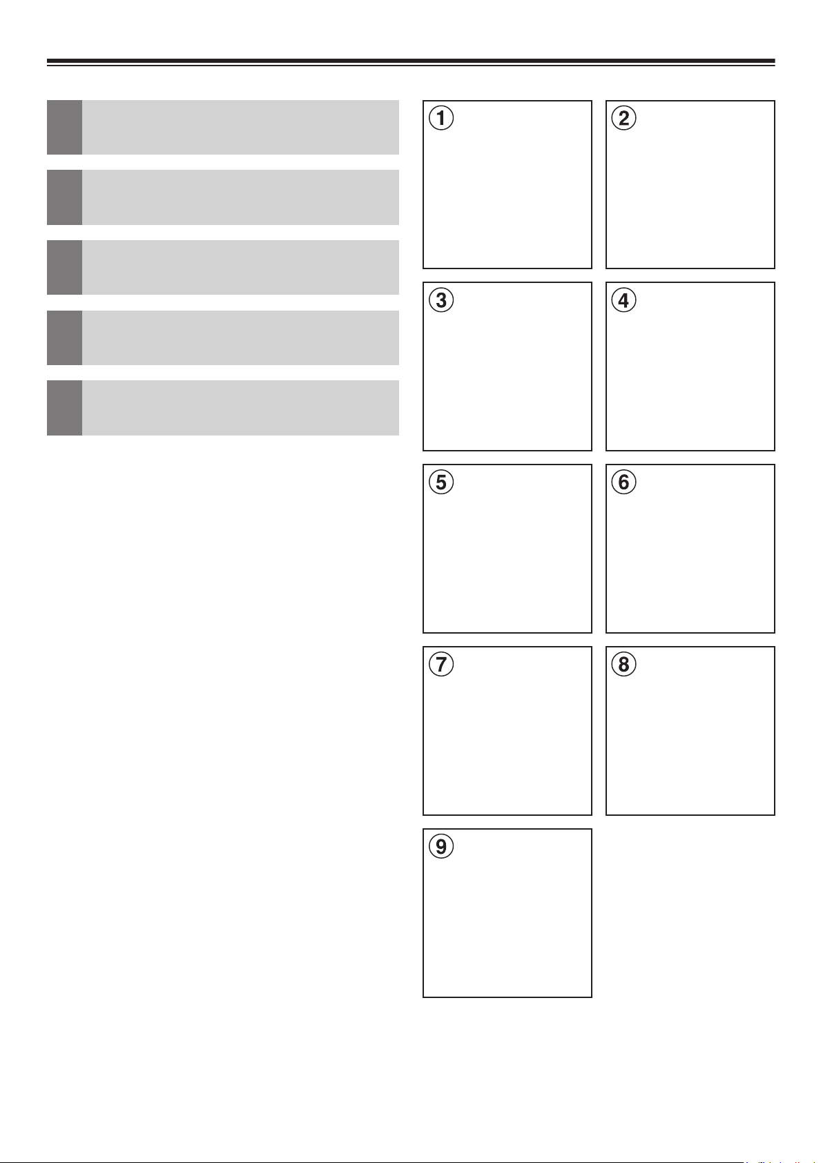
Parts list (1-9)
EN
T eileliste (1-9)
DE
Liste de pièces (1-9)
FR
Lista de piezas (1-9)
ES
Elenco dei componenti (1-9)
IT
2
Page 9

EN
FR
IT
1 A VN Unit
2 Display
3 Display housing with
keys and cable
4 Bracket for A VN Unit
5 Bracket for Display
6 Power Harness,
Display cable
7 GPS Antenna
8 USB Extension
9 Antenna Adapter
1 Ensemble A VN
2 Écran
3 Boîtier de l'écran avec
touches et câble
4 Support de
l’ensemble A VN
5 Support de l’écran
6 Faisceau d’alimentation,
câble d'écran
7 Antenne GPS
8 Rallonge USB
9 Adaptateur d'antenne
1 Unità A VN
2 Display
3 Alloggiamento del
display con tasti e cavo
4 Staffa per unità A VN
5 Staffa per display
6 Cablaggio di
alimentazione,
cavo del display
7 Antenna GPS
8 Prolunga USB
9 Adattatore antenna
DE
1 A VN-Gerät
2 Display
3 Displaygehäuse mit
Tasten und Kabel
4 Halterung für AVN-Gerät
5 Halterung für Display
6 Stromversorgungs-
kabelbaum,
Displaykabel
7 GPS Antenne
8 USB Verlängerung
9 Antennen Adapter
ES
1 Unidad A VN
2 Pantalla
3 Carcasa de la pantalla
con las teclas y el cable
4 Soporte para la
unidad A VN
5 Soporte para la pantalla
6 Arnés de alimentación,
cable para la pantalla
7 Antena GPS
8 Cable prolongador USB
9 Adaptador de antena
3
Page 10
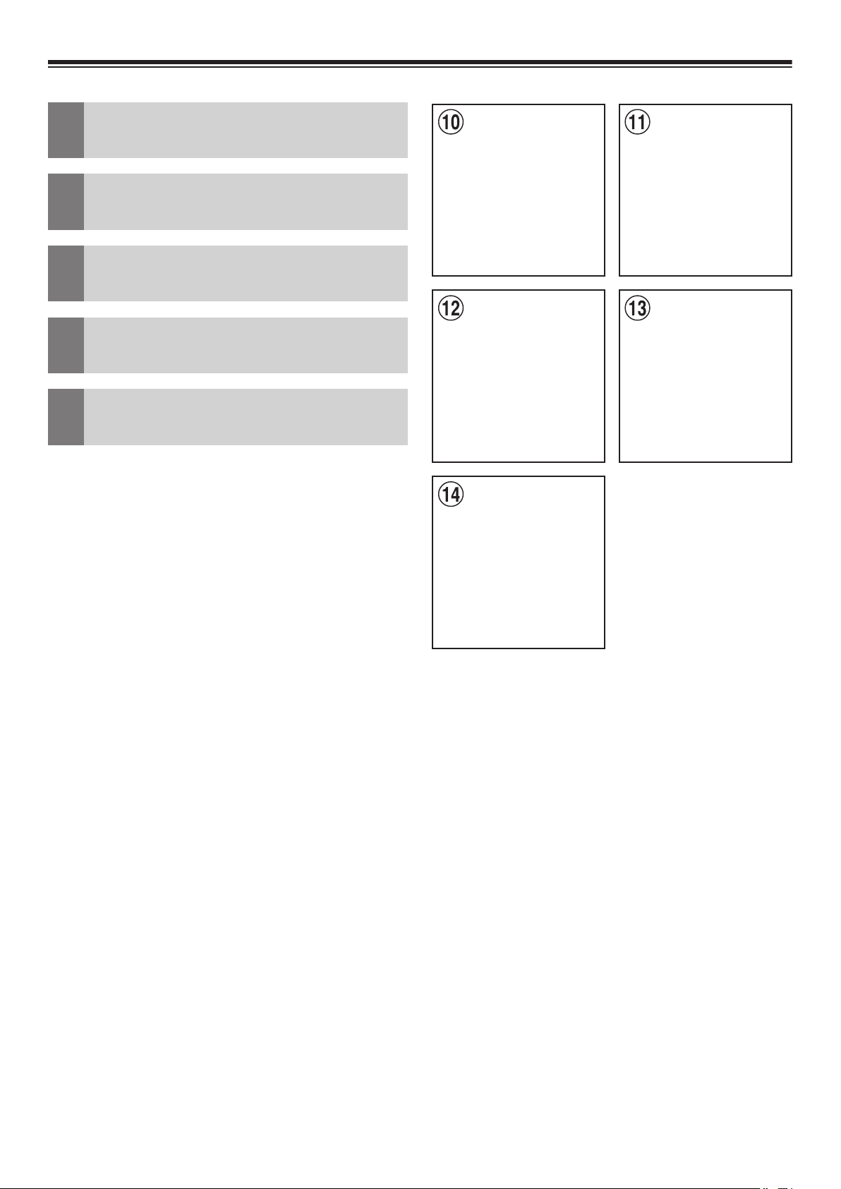
Required T ools
EN
(10-14)
Werkzeuge
DE
(10-14)
Outils nécessaires
FR
(10-14)
Herramientas necesarias
ES
(10-14)
Attrezzi necessari
IT
(10-14)
4
Page 11

EN
FR
IT
0 PH1 Screwdriver
! PH2 Screwdriver
@ T25 Screwdriver
# 2 mm Allen Key
$ 8 mm Spanner
0 Tournevis PH1
! Tournevis PH2
@ T ournevis T25
@ Clé Allen 2 mm
$ Clé 8 mm
0 Cacciavite PH1
! Cacciavite PH2
@ Cacciavite T25
@ Cacciavite a brugola
da 2 mm
$ Chiave da 8 mm
DE
0 PH1 Schraubendreher
! PH2 Schraubendreher
@ T25 Schraubendreher
# 2 mm Inbusschlüssel
$ 8 mm Maulschlüssel
ES
0 Destornillador PH1
! Destornillador PH2
@ Destornillador T25
# Llave Allen de 2 mm
$ Llave de tornillos de
8 mm
5
Page 12
Disconnection of battery
EN
T rennen der Batterie vom
DE
Stromnetz
Déconnexion de la batterie
FR
Desconexión de la batería
ES
Distacco della batteria
IT
- +
BAT
6
Page 13
EN
ES
WARNING:
Make sure to disconnect the cable from the
negative battery terminal before proceeding.
Follow car manufacturer’s guidelines.
DE
WARNUNG:
Entfernen Sie das Kabel vom Minuspol der
Batterie, bevor Sie fortfahren.
ADVERTENCIA:
Antes de proceder, asegúrese de desconectar el cable del terminal negativo de la
batería.
Siga las instrucciones del fabricante del
coche.
IT
AVVERTENZA:
Prima di procedere, scollegare il cavo dal
terminale negativo della batteria.
Befolgen Sie die Vorgaben des Fahrzeugherstellers.
FR
AVERTISSEMENT :
N'oubliez pas de débrancher le câble de la
borne négative de la batterie avant toute
intervention.
Respectez les directives du constructeur
de la voiture.
Attenersi alle istruzioni del costruttore del
veicolo.
7
Page 14
Installation (1‑4)
EN
Einbau (1‑4)
DE
Installation (1‑4)
FR
Instalación (1‑4)
ES
Installazione (1‑4)
IT
1
2
3
8
4
Page 15

EN
ES
Fiat Ducato with radio preparation: If the
car is not equipped with this part (1), replace
the radio dock with the following FIAT
original part: 735535319 (more details on
page 34).
Remove the compartment.
Release and remove four screws.
Position of the 4 screws.
DE
Fiat Ducato mit Radiovorbereitung (ISO
Stecker): Sollten Sie im Fiat Ducato nicht
diese Radio-Blende vornden (1), ersetzen
Sie den Radioschacht mit dem folgenden
FIAT Originalteil: 735535319 (weitere
Details auf Seite 34)
Fiat Ducato con preinstalación de radio:
Si el coche no va equipado con esta pieza
(1) sustituya el receptáculo de la radio por
la siguiente pieza original de FIAT:
735535319 (más información en la página
34).
Retire el compartimento.
Suelte y extraiga los cuatro tornillos.
Ubicación de los 4 tornillos.
IT
Fiat Ducato con predisposizione radio: se
l’autoveicolo è privo di questo componente
(1), sostituire il vano della radio con il
seguente componente originale FIAT:
735535319 (ulteriori dettagli a pagina
34).
Entfernen Sie das Ablagefach.
Schrauben Sie die vier Schrauben heraus.
Position der vier Schrauben.
FR
Fiat Ducato avec préparation radio : Si le
véhicule n'est pas équipé de cette pièce
(1), remplacer le socle de la radio avec la
pièce d'origine FIAT suivante : 735535319
(plus de détails à la page 34).
Déposez le compartiment.
Desserrez et déposez les quatre vis.
Position des 4 vis.
Rimuovere il vano.
Allentare e rimuovere le quattro viti.
Posizione delle 4 viti.
9
Page 16

Installation (5‑8)
EN
Einbau (5‑8)
DE
Installation (5‑8)
FR
Instalación (5‑8)
ES
Installazione (5‑8)
IT
5
6
7
10
8
Page 17

EN
ES
Open the note pad holder .
Release both screws and remove the
holder.
Now you have access to the space for GPS
Antenna installation and routing of further
signal cables and antenna leads.
Remove the cover of the fuse box.
DE
Klappen Sie den Notizbretthalter auf.
Lösen Sie die beiden Schrauben und
entfernen Sie den Halter .
Abra el soporte para blocs de notas.
Suelte ambos tornillos y retire el soporte.
De esta forma ya puede acceder al espacio
para la instalación de la antena GPS y de
otros cables de señal y de antenas.
Retire la cubierta de la caja de fusibles.
IT
Aprire il supporto del bloc-notes.
Rilasciare entrambe le viti e rimuovere il
supporto.
Nun haben Sie den Platz geschaffen,
zum Einbau der GPS Antenne und die
Durchführung weiterer Signalleitungen und
Antennen.
Entfernen Sie den Deckel des
Sicherungskastens.
FR
Ouvrez le support de bloc-notes.
Desserrez les deux vis et retirez le support.
Vous avez maintenant accès à l'espace
d'installation de l'antenne GPS et d'acheminement des autres câbles de signaux et
ls d'antenne. .
Ora è possibile accedere allo spazio per
l’installazione dell’antenna GPS e la posa
di ulteriori cavi di segnale e dell’antenna.
Rimuovere il coperchio della scatola fusibili.
Déposez le cache du boîtier de fusibles.
11
Page 18

Installation (9‑12)
EN
Einbau (9‑12)
DE
Installation (9‑12)
FR
Instalación (9‑12)
ES
Installazione (9‑12)
IT
9
10
11
12
12
Page 19

EN
ES
Fusebox
Disconnect the two 60 pin connectors
below and remove the housings.
Left connecor (green):
Pin 4 = Reverse Light
Right Connector (black):
Pin 56 = Speed Pulse
More details for model years 2006 - 201 1
on page 38.
DE
Sicherungskasten
Ziehen Sie die zwei unteren 60 Pol-Stecker
ab und entfernen Sie die Steckergehäuse.
Caja de fusibles
Desconecte los dos conectores de 60 cla-
vijas de abajo y retire las carcasas.
Conector izquierdo (verde):
Clavija 4 = Luz de marcha atrás
Conector derecho (negro):
Clavija 56 = Impulso de velocidad
Más detalles para los años de modelo 2006
- 201 1 en la página 38.
IT
Scatola fusibili
Scollegare i due connettori a 60 pin indicati
sotto e rimuovere gli alloggiamenti.
Linker Stecker (grün):
Pin 4 = Rückfahrscheinwerfer
Rechter Stecker (schwarz):
Pin 56 = Geschwindigkeitsimpuls
Weitere Details zu den Modelljahren 2006
- 201 1 auf Seite 38.
FR
Boîtier de fusibles
Déconnectez les deux connecteurs à
60 broches du bas et déposez les boîtiers.
Connecteur gauche (vert) :
Broche 4 = feu de recul
Connecteur droit (noir) :
Broche 56 = impulsion de vitesse
Connettore lato sinistro (verde):
Pin 4 = Luce retromarcia
Connettore lato destro (nero):
Pin 56 = Impulsi velocità
Maggiori dettagli per anni di modello 2006
- 201 1 a pagina 38.
Plus de détails pour les années modèle
2006 - 201 1 à la page 38.
13
Page 20

Installation (13‑16)
EN
Einbau (13‑16)
DE
Installation (13‑16)
FR
Instalación (13‑16)
ES
Installazione (13‑16)
IT
13
14
15
14
16
Page 21

EN
ES
Insert the green-white lead (Speed Pulse)
into the free chamber (56) of the black
connector.
Connect the orange-white lead to the lead
of the reverse light (Pin 4 of the green
connector).
Route the three leads behind the fuse box,
along the radio harness to the radio dock.
Attach the note pad holder with the two rear
screws.
DE
Stecken Sie die grün-weiße Leitung (Speed
Pulse) in Kammer 56 des schwarzen Steckers.
Verbinden Sie die orange-weiße Leitung
(Reverse) mit der Leitung des Rückfahrscheinwerfersignals, Kammer 4 des grünen
Steckers.
Introduzca el cable verde-blanco (impulso
de velocidad) en el hueco vacío (56) del
conector negro.
Conecte el cable naranja-blanco al cable
de la luz de marcha atrás (clavija 4 del
conector verde).
Pase los tres cables por detrás de la caja
de fusibles a través del arnés de cables de
la radio hasta el receptáculo de la radio.
Fije el soporte para blocs de notas con los
dos tornillos traseros.
IT
Inserire il cavo verde-bianco (impulsi
velocità) nel vano libero (56) del connettore
nero.
Collegare il cavo arancio-bianco al cavo
della luce della retromarcia (pin 4 del
connettore verde).
Verlegen Sie die drei Kabel hinter dem
Sicherungskasten, entlang des Kabelbaums
zum Radioschacht und befestigen Sie
danach den Notizbretthalter mit den zwei
hinteren Schrauben.
FR
Insérez le l vert-blanc (impulsion de
vitesse) dans le logement libre (56) du
connecteur noir .
Raccordez le l orange-blanc au l du feu
de recul (broche 4 du connecteur vert).
Acheminer les trois ls derrière le boîtier de
fusibles le long du faisceau de la radio
jusqu'au socle de la radio. Fixez le support
de bloc-notes à l'aide des deux vis arrière.
Far passare i tre cavi dietro la scatola
fusibili, lungo il cablaggio della radio verso
il relativo vano. Fissare il supporto del blocnotes con le due viti posteriori.
15
Page 22

Installation (17‑20)
EN
Einbau (17‑20)
DE
Installation (17‑20)
FR
Instalación (17‑20)
ES
Installazione (17‑20)
IT
17
18
19
16
20
Page 23

EN
ES
Brackets for the A VN Unit
Tilt the brackets to insert into radio dock.
Bring the brackets into the shown position.
Fix the brackets with the 4 original screws.
DE
Halterung für den Monitor/ A VN-Gerät
Kippen Sie die Halterung in das Radio-
Dock ein.
Soportes para la unidad A VN
Incline los soportes para introducirlos en el
receptáculo de la radio.
Coloque los soportes en la posición
mostrada.
Fije los soportes con los 4 tornillos
originales.
IT
Staffe per l’unità A VN
Inclinare le staffe per inserirle nel vano
radio.
Setzen Sie die Halterung in der richtigen
Position.
Schrauben Sie die Halterungen mit den
vier Originalschrauben fest.
FR
Supports de l’ensemble A VN
Inclinez les supports pour les insérer dans
le socle de la radio.
Positionnez les supports comme illustré.
Fixez les supports à l’aide des 4 vis d’origine.
Portare le staffe nella posizione mostrata.
Fissare le staffe con le 4 viti originali.
17
Page 24

Installation (21‑24)
EN
Einbau (21‑24)
DE
Installation (21‑24)
FR
Instalación (21‑24)
ES
Installazione (21‑24)
IT
21
22
23
18
24
Page 25

EN
ES
Brackets for A VN unit
A VN Unit
Attach the bracket with two screws on the
left side of the A VN unit.
Attach the bracket with two screws on the
right side of the A VN unit.
DE
Halterung für das A VN-Gerät
AVN-Gerät
Soportes para la unidad A VN
Unidad A VN
Fije el soporte con dos tornillos en el lado
izquierdo de la unidad A VN.
Fije el soporte con dos tornillos en el lado
derecho de la unidad A VN.
IT
Staffa per unità A VN
Unità A VN
Befestigen Sie die Halterung mit zwei
Schrauben an der linken Seite des
AVN-Geräts.
Befestigen Sie die Halterung mit zwei
Schrauben an der rechten Seite des
AVN-Geräts.
FR
Support de l’ensemble A VN
Ensemble A VN
Fixez le support à l’aide de deux vis sur le
côté gauche de l’ensemble A VN.
Fixez le support à l’aide de deux vis sur le
côté droit de l’ensemble A VN.
Fissare la staffa con due viti sul lato sinistro
dell’unità A VN.
Fissare la staffa con due viti sul lato destro
dell’unità A VN.
19
Page 26

Installation (25‑28)
DAB Antenna
FM Antenna
AVN Unit
EN
Einbau (25‑28)
DE
Installation (25‑28)
FR
Instalación (25‑28)
ES
Installazione (25‑28)
IT
25
26
27
20
28
Page 27

EN
ES
Connect the vehicle specic harness with
the A VN unit.
Key harness
Connect antenna plugs as shown (27)(28).
DE
Verbinden Sie den fahrzeugspezischen
Kabelbaum mit dem A VN-Gerät.
Tastenkabel
Conecte el arnés especíco del vehículo a
la unidad A VN.
Arnés para las teclas
Conectar los conectores de antena tal y
como se muestra (27)(28).
IT
Collegare il cablaggio specico per il veicolo
all’unità A VN.
Cablaggio dei tasti
Verbinden Sie die Antennenstecker wie
gezeigt (27)(28).
FR
Raccordez le faisceau spécique du
véhicule à l’ensemble A VN.
Faisceau de touche
Connectez les prises d’antenne comme
indiqué (27)(28).
Connettere l’antenna come mostrato in
gura (27)(28).
21
Page 28

Installation (29‑32)
EN
Einbau (29‑32)
DE
Installation (29‑32)
FR
Instalación (29‑32)
ES
Installazione (29‑32)
IT
29
30
31
22
32
Page 29

EN
ES
Insert the vehicle‘s ISO connector .
Insert the A VN unit into the radio dock.
Hex socket screws to attach brackets.
Attach the display brackets with the four
hex socket screws.
DE
Verbinden sie die ISO-Buchse mit dem
werksseitigen Radiostecker .
Setzen Sie das AVN-Gerät in das RadioDock ein.
Inbusschrauben zum Verbinden der Halterungen.
V erschrauben Sie die Halterungen mit den
vier Inbusschrauben.
Introduzca el conector ISO del vehículo.
Introduzca la unidad A VN en el receptáculo
de la radio.
Tornillos Allen para jar los soportes.
Fije los soportes de la pantalla con los
cuatro tornillos Allen.
IT
Inserire il connettore ISO del veicolo.
Inserire l’unità A VN nel vano della radio.
Viti a brugola esagonale per il ssaggio
delle staffe.
Fissare le staffe del display con le quattro
viti a brugola esagonale.
FR
Introduisez le connecteur ISO du véhicule.
Introduisez l’ensemble AVN dans le socle
de la radio.
Vis à six pans creux pour xer les supports.
Fixez les supports de l’écran à l’aide des
quatre vis à six pans creux.
23
Page 30

Installation (33‑36)
EN
Einbau (33‑36)
DE
Installation (33‑36)
FR
Instalación (33‑36)
ES
Installazione (33‑36)
IT
33
34
35
24
36
Page 31

EN
ES
Rear display housing
Connect the key harness to the keyboard in
the display housing.
Attach the display housing to the dash
board.
Make sure that the display power- and
signal cable, as well as the microphone
cable are accessible.
DE
Hintere Monitorverkleidung
Verbinden Sie die Tastenkabel mit den
Tasten des Monitorgehäuses.
Carcasa trasera de la pantalla
Conecte el arnés para las teclas al teclado
de la carcasa de la pantalla.
Fije la carcasa de la pantalla en el
salpicadero.
Asegúrese de que el cable de alimentación
y el de señal de la pantalla, así como el del
micrófono, se encuentran accesibles.
IT
Alloggiamento posteriore del display
Collegare il cablaggio dei tasti alla tastiera
nell’alloggiamento del display .
Bringen Sie das Monitorgehäuse am
Armaturenbrett an.
Stellen Sie sicher , dass Monitor Strom- und
Signalkabel des Monitors, sowie das Mikrofonkabel zugänglich sind.
FR
Boîtier arrière de l’écran
Raccordez le faisceau de touche au clavier
dans le boîtier de l’écran.
Fixez le boîtier de l’écran au tableau de
bord.
Assurez-vous que le câble d’alimentation
et de signaux de l’écran, ainsi que le câble
du microphone sont accessibles.
Fissare l’alloggiamento del display al
cruscotto.
Vericare che siano accessibili i cavi di
alimentazione e segnale del display , nonché
il cavo del microfono.
25
Page 32

Installation (37‑40)
EN
Einbau (37‑40)
DE
Installation (37‑40)
FR
Instalación (37‑40)
ES
Installazione (37‑40)
IT
37
38
39
26
40
Page 33

EN
ES
Bracket for display
Attach to the top of the AVN bracket. Make
sure the display cables can move easily .
Fix with four supplied screws.
Position of the screws.
DE
Monitorhalterung
Setzen Sie die Halterung auf die AVN-
Halterung. Achten Sie darauf, dass die
Monitor-Anschlusskabel freigängig bleiben.
Soporte para la pantalla
Fije la parte superior del soporte para A VN.
Asegúrese de que los cables para la
pantalla se pueden mover con facilidad.
Fíjelo con los cuatro tornillos incluidos.
Ubicación de los tornillos.
IT
Staffa per display
Fissare alla parte superiore della staffa A VN.
Vericare che i cavi del display possano
muoversi con facilità.
Verschrauben Sie beides mit den vier
mitgelieferten Schrauben.
Position der vier Schrauben.
FR
Support de l’écran
Fixez-le en haut du support de l’AVN.
Assurez-vous que les câbles peuvent être
déplacés facilement.
Fixez à l’aide des quatre vis fournies.
Position des vis.
Fissare con le quattro viti in dotazione.
Posizione delle viti.
27
Page 34

Installation (41‑44)
EN
Einbau (41‑44)
DE
Installation (41‑44)
FR
Instalación (41‑44)
ES
Installazione (41‑44)
IT
41
42
43
28
44
Page 35

EN
ES
Display
Connect the signal cable and the power
connector to the display .
Insert the supplied hex screws to the
display and screw them in halfway .
Insert the display to the bracket and x the
four hex screws.
DE
Display
Verbinden Sie das Signal-Kabel und die
Stromversorgung mit dem Display .
Pantalla
Conecte el cable de señal y el conector de
alimentación a la pantalla.
Introduzca los tornillos Allen incluidos en la
pantalla y atorníllelos hasta la mitad.
Introduzca la pantalla en el soporte y acabe
de atornillar los cuatro tornillos Allen.
IT
Display
Collegare il cavo del segnale e il connettore
di alimentazione al display .
Drehen Sie die vier mitgelieferten 8 mm
Sechskantschrauben bis zur Hälfte in den
Monitor rein.
Setzen Sie das Display in die Halterung
ein, ziehen Sie die vier Sechkantschrauben
fest.
FR
Écran
Raccordez le câble de signaux et le
connecteur d’alimentation à l’écran.
Introduisez les vis à six pans creux fournies
dans l’écran et vissez-les à moitié.
Introduisez l’écran dans le support et xez
les quatre vis à six pans creux.
Inserire le viti esagonali in dotazione nel
display e avvitarle per metà.
Inserire il display nella staffa e ssare le
quattro viti esagonali.
29
Page 36

Installation (45‑48)
EN
Einbau (45‑48)
DE
Installation (45‑48)
FR
Instalación (45‑48)
ES
Installazione (45‑48)
IT
45
46
47
30
48
Page 37

EN
ES
Front display housing with two screws and
screw covers
Connect the microphone cable.
Insert the bottom part of the display frame
into the groove.
Tilt the frame top until in nal position.
DE
Display-Blende mit zwei Schrauben und
zwei Blindstopfen
V erbinden sie das Mikrofonkabel.
Carcasa delantera de la pantalla con dos
tornillos y tapas para los tornillos
Conecte el cable del micrófono.
Introduzca la parte inferior del marco de la
pantalla en la ranura.
Incline la parte superior del marco hasta
colocarlo en su posición nal.
IT
Cornice anteriore del display con due viti e
relative coperture
Collegare il cavo del microfono.
Setzen Sie die Display-Blende zuerst unten
in die dafür vorgesende Führung ein.
Neigen Sie die Blende oben in die Endposition.
FR
Boîtier avant de l’écran avec deux vis et
cache vis
Raccordez le câble du microphone.
Introduisez la partie basse du cadre de
l’écran dans la gorge.
Inclinez le haut du cadre jusqu’à sa position
nale.
Inserire la parte inferiore della cornice del
display nell’apposita scanalatura.
Inclinare la parte superiore della cornice no
a portare quest’ultima nella posizione nale.
31
Page 38

Installation (49‑52)
EN
Einbau (49‑52)
DE
Installation (49‑52)
FR
Instalación (49‑52)
ES
Installazione (49‑52)
IT
49
50
51
32
52
Page 39

EN
ES
T wo screws and screw covers
Attach the frame with the two supplied
screws to the monitor housing.
Cover the screws.
Overview
DE
Zwei Schrauben und zwei Blindstopfen
Verschrauben Sie die Blende mit den zwei
mitgelieferten Schrauben am Monitorgehäuse.
V erschliessen Sie die Schraubenöffnungen
mit den zwei Blindstopfen.
Dos tornillos y sus tapas
Fije el marco a la carcasa de la pantalla con
los dos tornillos incluidos.
Tape los tornillos.
Visión de conjunto
IT
Due viti con relative coperture
Fissare la cornice all’alloggiamento del
display con le due viti in dotazione.
Coprire le viti.
Panoramica
Übersicht
FR
Deux vis et cache vis
Fixez le cadre sur le boîtier de l’écran à
l’aide des vis fournies.
Couvrez les vis.
Vue d’ensemble
33
Page 40

Installation (53)
EN
Einbau (53)
DE
Installation (53)
FR
Instalación (53)
ES
Installazione (53)
IT
34
Part Nr. / Part Nr. / Réf. / N.º de pieza / N. part.: 735535319
53
Page 41

EN
ES
If the car is not equipped with this part,
replace the radio dock with the following
FIA T original part: 735535319.
DE
Sollten Sie im Fiat Ducato nicht diese
Radio-Blende vornden, ersetzen Sie den
Radioschacht mit dem folgenden FIAT
Originalteil: 735535319.
Si el coche no va equipado con esta
pieza sustituya el receptáculo de la radio
por la siguiente pieza original de FIAT:
735535319.
IT
Se l’autoveicolo è privo di questo
componente, sostituire il vano della radio
con il seguente pezzo originale FIAT:
735535319.
FR
Si le véhicule n’est pas équipé de cette
pièce, remplacer le socle de la radio
avec la pièce d’origine FIAT suivante :
735535319.
35
Page 42

Changing the illumination
A
C
E
D
B
EN
Color of the Keys
Farbe der T astenbeleuchtung
DE
ändern
Modication de la teinte
FR
d’éclairage des touches
Cambio del color de
ES
iluminación de las teclas
V ariazione del colore di
IT
illuminazione dei tasti
Color Presets Farbvoreinstellungen Présélections de teintes
1. Red
2. Red (dim)
3. Blue
4. Blue (dim)
5. Green
6. Green (dim)
7. Orange
8. Orange (dim)
9. Yellow
10. Yellow (dim)
11. White
12. White (dim)
Colores predeterminados Colori preimpostati
1. Rojo
2. Rojo (atenuado)
3. Azul
4. Azul (atenuado)
5. Verde
6. V erde (atenuado)
7. Naranja
8. Naranja (atenuado)
9. Amarillo
10. Amarillo (atenuado)
11. Blanco
12. Blanco (atenuado)
1. Rot
2. Rot (gedimmt)
3. Blau
4. Blau (gedimmt)
5. Grün
6. Grün (gedimmt)
7. Orange
8. Orange (gedimmt)
9. Gelb
10. Gelb (gedimmt)
11. Weiß
12. W eiß (gedimmt)
1. Rosso
2. Rosso (tenue)
3. Blu
4. Blu (tenue)
5. Verde
6. V erde (tenue)
7. Arancione
8. Arancione (tenue)
9. Giallo
10. Giallo (tenue)
11. Bianco
12. Bianco (tenue)
1. Rouge
2. Rouge (atténué)
3. Bleu
4. Bleu (atténué)
5. Vert
6. V ert (atténué)
7. Orange
8. Orange (atténué)
9. Jaune
10. Jaune (atténué)
11. Blanc
12. Blanc (atténué)
36
Page 43

EN
ES
T welve illumination presets are available to
choose from. See table for details. T o toggle
the colors, push keys ‘V oice’ (A), ‘–’ (C) and
‘Mute’ (E) simultaneously. Repeat until
desired color is selected.
DE
Zwölf Beleuchtungs-V oreinstellungen stehen
zur Auswahl. Siehe T abelle. Drücken Sie zum
Wechseln der Farben gleichzeitig auf die
Tasten „Sprache“ (A), „–“(C) und „Stumm“
(E). Wiederholen, bis die gewünschte Farbe
ausgewählt ist.
Existen doce tipos de iluminación predeterminados entre los que elegir. Consulte la
tabla para obtener más detalles. Para
alternar los colores pulse las teclas “Voz”
(A), “–” (C) y “Silenciar” (E) a la vez. Repita
este paso hasta seleccionar el color
deseado.
IT
È possibile scegliere tra dodici colori
preimpostati di illuminazione. Per maggiori
informazioni, vedere la tabella. Per cambiare
colore, premere contemporaneamente i tasti
"Voce" (A), "–" (C) e "Silenziamento" (E).
Ripetere l’operazione no a selezionare il
colore desiderato.
FR
Douze présélections d’éclairage sont
disponibles. Consultez le tableau pour les
détails. Pour changer de teinte, pressez
simultanément les touches "Voix" (A), "–"
(C) et "Coupure du son" (E). Répétez
jusqu’à obtention de la teinte désirée.
37
Page 44

Model years 2006 – 201 1:
EN
FR
Année modèle 2006 – 201 1:
Modelljahre 2006 ‑ 201 1:
DE
Année modèle 2006 – 201 1:
FR
Modelos del 2006 – 201 1:
ES
Modello anno 2006 – 201 1:
IT
EN
Model years 2006 – 201 1:
Fuse box, blue 52 pin connector , pin 10 in
the grey part, grey/green cable =
speedpulse.
Boîte à fusibles, connecteur bleu à 52
broches, broche 10 dans la partie grise,
câble gris / vert = vitesse.
Boîte à fusibles, connecteur noir gauche,
broche 8, câble blanc / rouge = éclairage
inversé.
ES
Modelos del 2006 – 201 1:
Caja de fusibles, conector Azul de 52 pines,
pin 10 en la parte Gris, cable Gris/Verde =
Pulso de velocidad.
Fuse box, left black connector , pin 8, white/
red cable = reverse light.
DE
Modelljahre 2006 - 201 1:
Sicherungskasten, blauer , 52 poliger
Steckverbinder , Pin 10 im grauen T eil, grau/
grünes Kabel = Geschwindigkeitsimpuls.
Sicherungskasten, schwarzer
Steckverbinder links, Pin 8, weiss/ rot =
Rückfahrscheinwerfer.
Caja de fusibles, conector Negro izquierdo,
pin 8, cable Blanco/Rojo = Señal de marcha
atrás.
IT
Modello anno 2006 – 201 1:
Scatola dei fusibili, Pin 52 del connettore blu,
pin 10 nella parte grigia, cavo grigio/verde =
speedpulse.
Scatola dei fusibili, connettore nero a sinistra,
pin 8, cavo bianco/rosso = segnale reverse.
38
Page 45

Connections/
Anschlüsse/
Raccordements/
Conexiones/
Collegamenti
39
Page 46

Memo
EN
Notizen
DE
Mémo
FR
.................................................................
.................................................................
.................................................................
.................................................................
.................................................................
Notas
ES
Note
IT
.................................................................
.................................................................
.................................................................
.................................................................
.................................................................
.................................................................
.................................................................
.................................................................
.................................................................
.................................................................
.................................................................
.................................................................
.................................................................
.................................................................
.................................................................
.................................................................
.................................................................
.................................................................
.................................................................
.................................................................
.................................................................
.................................................................
.................................................................
.................................................................
.................................................................
.................................................................
.................................................................
.................................................................
.................................................................
.................................................................
.................................................................
.................................................................
.................................................................
.................................................................
Page 47

Page 48

ALPINE ELECTRONICS MARKETING, INC.
1-7, Yukigaya-Otsukamachi, Ota-ku,
Tokyo 145-0067, JAPAN
Phone: 03-5499-4531
ALPINE ELECTRONICS OF AMERICA, INC.
19145 Gramercy Place, To rrance,
California 90501, U.S.A.
Phone 1-800-ALPINE-1 (1-800-257-4631)
ALPINE ELECTRONICS OF CANADA, INC.
777 Supertest Road, Toronto,
Ontario M3J 2M9, Canada
Phone 1-800-ALPINE-1 (1-800-257-4631)
ALPINE ELECTRONICS OF AUSTRALIA PTY. LT D.
161-165 Princes Highway, Hallam
Victoria 3803, Australia
Phone 03-8787-1200
ALPINE ELECTRONICS GmbH
Wilhelm-Wagenfeld-Str. 1-3, 80807 München, Germany
Phone 089-32 42 640
ALPINE ELECTRONICS OF U.K. LTD.
Alpine House
Fletchamstead Highway, Coventry CV4 9TW, U.K.
Phone 0870-33 33 763
ALPINE ELECTRONICS FRANCE S.A.R.L.
Phone 01-48638989
ALPINE ITALIA S.p.A.
Viale C. Colombo 8, 20090 Trezzano
Sul Naviglio (MI), Italy
Phone 02-484781
ALPINE ELECTRONICS DE ESPAÑA, S.A.
Portal de Gamarra 36, Pabellón, 32
01013 Vitoria (Alava)-APDO 133, Spain
Phone 945-283588
184, Allée des Erables
CS 52016 - Villepinte
95 945 Roissy CDG Cedex, France
Designed by Alpine Electronics (Europe) GmbH
Printed in Germany
R
 Loading...