

Page 1

Page 2

Page 3

PXA-H900
Multimedia Manager™
• OWNER'S MANUAL
Please read before using this equipment.
• MODE D'EMPLOI
Veuillez lire avant d’utiliser cet appareil.
• MANUAL DE OPERACIÓN
Léalo antes de utilizar este equipo.
R
ENGLISHFRANÇAISESPAÑOL
®
®
Page 4

Page 5

Contents
WARNING
WARNING............................................. 2
CAUTION.............................................. 3
PRECAUTIONS....................................3
Basic Operation
Remote control unit ..................................... 4
Resetting ...................................................... 6
Turning the power on and off ...................... 6
About indicators .......................................... 7
Setting the speakers ..................................... 8
Using with Ai-NET connections ................. 9
Using with RCA-type or optical cable
connections
(non Ai-NET connections)......................10
Automatic Adjustments
Preparations for automatic adjustments .... 14
Automatic adjustments
(Adaptive Equalizer)...............................16
Performing time correction automatically
(Precision Automated Time Correction) .. 20
Settings/Adjustments
Performing time correction manually
(Time Correction) ................................... 24
Equalizer adjustments................................ 28
Crossover network .....................................30
Crossover adjustment ................................ 32
Switching the phase ...................................34
Using Dolby Surround
Using the Pro Logic mode .........................36
Adjustment procedure for
Dolby Surround ...................................... 37
Speaker setup.............................................38
Adjusting the speaker levels ...................... 40
Center speaker time correction ..................42
Rear speaker time correction ..................... 44
Adjusting the acoustic image .................... 46
Mixing bass sound to the rear channel ...... 48
Achieving powerful high volume sound.... 50
Convenient Functions
Navigation system voice guidance
interruption ............................................. 51
Storing settings in the memory..................52
Calling out stored values ........................... 52
Defeat mode .............................................. 53
Switching the display mode ...................... 53
Switching the indicator color
(for non Ai-NET connections only) ........54
DTS ........................................................... 54
Information
Terminology .............................................. 55
In case of difficulty....................................56
Specifications ............................................ 58
LIMITED WARRANTY
1-EN
Page 6

WARNING
WARNING
This symbol means important instructions.
Failure to heed them can result in
serious injury or death.
DO NOT OPERATE ANY FUNCTION THAT
TAKES YOUR ATTENTION AWAY FROM
SAFELY DRIVING YOUR VEHICLE.
Any function that requires your prolonged
attention should only be performed after
coming to a complete stop. Always stop the
vehicle in a safe location before performing
these functions. Failure to do so may result in
an accident.
KEEP THE VOLUME AT A LEVEL WHERE YOU
CAN STILL HEAR OUTSIDE NOISE WHILE
DRIVING.
Failure to do so may result in an accident.
MINIMIZE DISPLAY VIEWING WHILE
DRIVING.
Viewing the display may distract the driver
from looking ahead of the vehicle and cause an
accident.
USE THE CORRECT AMPERE RATING WHEN
REPLACING FUSES.
Failure to do so may result in fire or electric
shock.
USE ONLY IN CARS WITH A 12 VOLT
NEGATIVE GROUND.
(Check with your dealer if you are not sure.)
Failure to do so may result in fire, etc.
DO NOT BLOCK VENTS OR RADIATOR
PANELS.
Doing so may cause heat to build up inside and
may result in fire.
DO NOT DISASSEMBLE OR ALTER.
Doing so may result in an accident, fire or
electric shock.
USE THIS PRODUCT FOR MOBILE 12V
APPLICATIONS.
Use for other than its designed application may
result in fire, electric shock or other injury.
KEEP SMALL OBJECTS SUCH AS BATTERIES
OUT OF THE REACH OF CHILDREN.
Swallowing them may result in serious injury.
If swallowed, consult a physician immediately.
2-EN
Page 7

CAUTION
PRECAUTIONS
This symbol means important instructions.
Failure to heed them can result in
injury or material property damage.
HALT USE IMMEDIATELY IF A PROBLEM
APPEARS.
Failure to do so may cause personal injury or
damage to the product. Return it to your
authorized Alpine dealer or the nearest Alpine
Service Center for repairing.
DO NOT MIX NEW BATTERIES WITH OLD
BATTERIES. INSERT WITH THE CORRECT
BATTERY POLARITY.
When inserting the batteries, be sure to observe
proper polarity (+ and –) as instructed. Rupture
or chemical leakage from the battery may
cause fire or personal injury.
Temperature
Be sure the temperature inside the vehicle is
between +60°C (+140°F) and –10°C (+14°F)
before turning your unit on.
Installation Location
Make sure the PXA-H900 will not be installed
in a location subjected to:
• Direct sun and heat
• High humidity and water
• Excessive dust
• Excessive vibrations
Maintenance
If you have problems, do not attempt to repair
the unit yourself. Return it to your Alpine
dealer or the nearest Alpine Service Station for
servicing.
3-EN
Page 8
Basic Operation
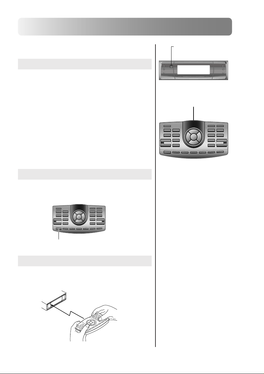
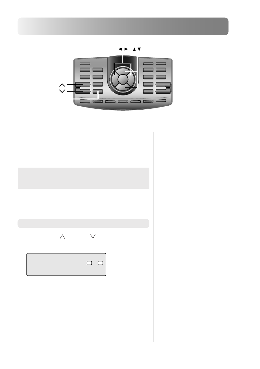
Remote control unit
When using the remote control unit
• Point the remote control unit’s transmitter at the remote
control sensor and operate it within a distance of 2
meters.
• Note that the remote control unit may not operate if the
remote control sensor is exposed to direct sunlight.
• The remote control unit is a compact, lightweight, high
precision device. To avoid damage, battery wear,
erroneous operation or reduced operability, be careful of
the following:
- Do not subject the remote control unit to shocks.
- Do not place it in pant pockets.
- Do not spill liquids on it.
- Avoid humidity and dust.
- Do not set it in places exposed to direct sunlight.
Remote control unit light
When the LIGHT button on the remote control unit is
pressed, the remote control unit’s light section turns on for
10 seconds.
Remote control sensor
Remote control transmitter
• When the remaining battery
power gets low, only the LIGHT
button lights.
LIGHT
Holding the remote control unit
Be careful not to cover the transmitter with your fingers,
etc., when operating the remote control unit.
4-EN
Page 9
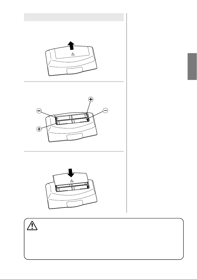
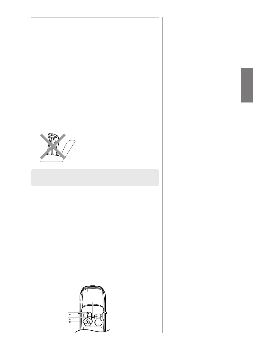
Loading batteries
Press down on the groove shown on the diagram
1
and push forward to remove the lid.
Load four “AAA” sized batteries in the indicated
2
directions.
Set the lid back in place and insert until a click is
3
heard.
• Use four “AAA” sized batteries.
WARNING
DO NOT OPERATE ANY FUNCTION THAT TAKES YOUR ATTENTION AWAY FROM SAFELY
DRIVING YOUR VEHICLE.
Any function that requires your prolonged attention should only be performed after coming to a
complete stop. Always stop the vehicle in a safe location before performing these functions.
Failure to do so may result in an accident.
5-EN
Page 10
Basic Operation
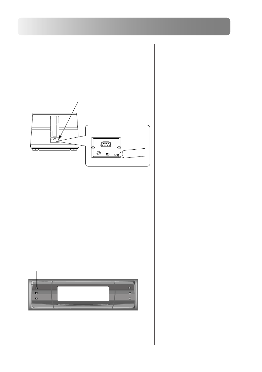
Resetting
Reset the unit when using it for the first time or after replacing the
vehicle’s battery.
Press the reset switch with the tip of a pen, etc.
1
Open the cover using a hexagonal wrench.
Reset switch
Turning the power on and off
This unit does not have a power switch. The head unit to which
the unit is connected, controls its power.
The power indicator lights when the power is
1
turned on.
Power indicator
6-EN
Page 11
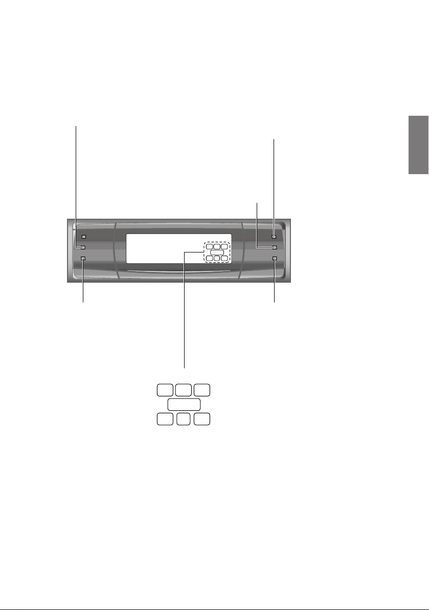
About indicators
HDCD indicator*
Lights amber in the HDCD decode
mode
PRO LOGIC indicator
Lights amber in the Dolby Surround
decode mode
LC
LFE
S
Ls Rs
Dolby Digital indicator
Lights amber in the Dolby Digital
decode mode
R
DTS indicator
Lights amber in the DTS
decode mode
Input signal indicators
These indicate the signals being input.
LFE
S
R
L: Left front channel
R: Right front channel
C: Center channel
Ls: Left surround channel
Rs: Right surround channel
S: Monaural surround signal
LFE: Low frequency deep bass signal
LC
Ls Rs
* When the Pro Logic mode is on during HDCD playback
• If “CENTER” or “REAR” is set to “ON” at “Speaker setup”, the HDCD indicator does not light.
• If both “CENTER” and “REAR” are set to “OFF” at “Speaker setup”, the HDCD indicator lights.
MPEG indicator
Lights amber in the MPEG2 decode
mode
7-EN
Page 12
Basic Operation
ENTER ,
MODE
TCR
ch UP
ch DN
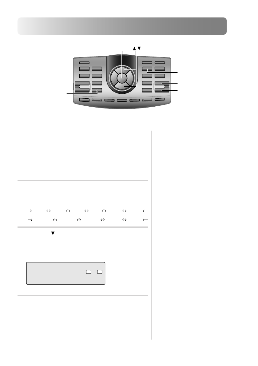
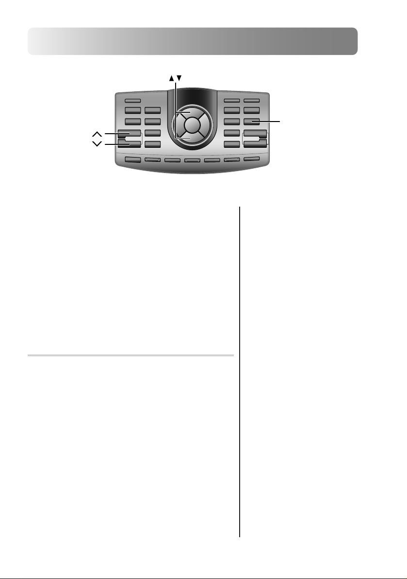
Setting the speakers
First make the speaker settings.
Turn off speaker channels that are not connected.
Press the TCR button.
1
Press the ch UP or ch DN button to select a
2
speaker channel to which no speaker is connected.
FLLOW FRLOW FRMID FLHIGHFLMID FRHIGH
Press the button to set the speaker level to
3
“OFF”.
Repeat steps 2 and 3 to turn “OFF” all non-
connected speaker channels.
TENETR0.0
CR C
()
L:OFFEVEL
Press the ENTER button to complete the setting.
4
[ms]
0.0 0.0
[[icmnch ]]/
LR
• Names of speakers displayed
FLLOW:
Front low range speaker (L)
FRLOW:
Front low range speaker (R)
FLMID :
Front mid range speaker (L)
FRMID :
Front mid range speaker (R)
FLHIGH :
Front high range speaker (L)
FRHIGH :
Front high range speaker (R)
REAR L :
REAR LREAR RCENTERSub Wf.LSub Wf.R
Rear speaker (L)
REAR R :
Rear speaker (R)
CENTER :
Center speaker
Sub Wf. L :
Subwoofer (L)
Sub Wf. R :
Subwoofer (R)
8-EN
Page 13
Using with Ai-NET
connections
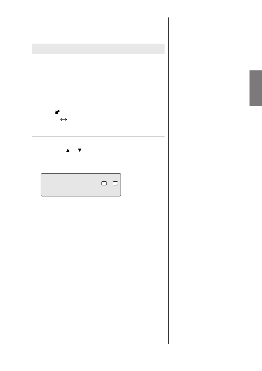
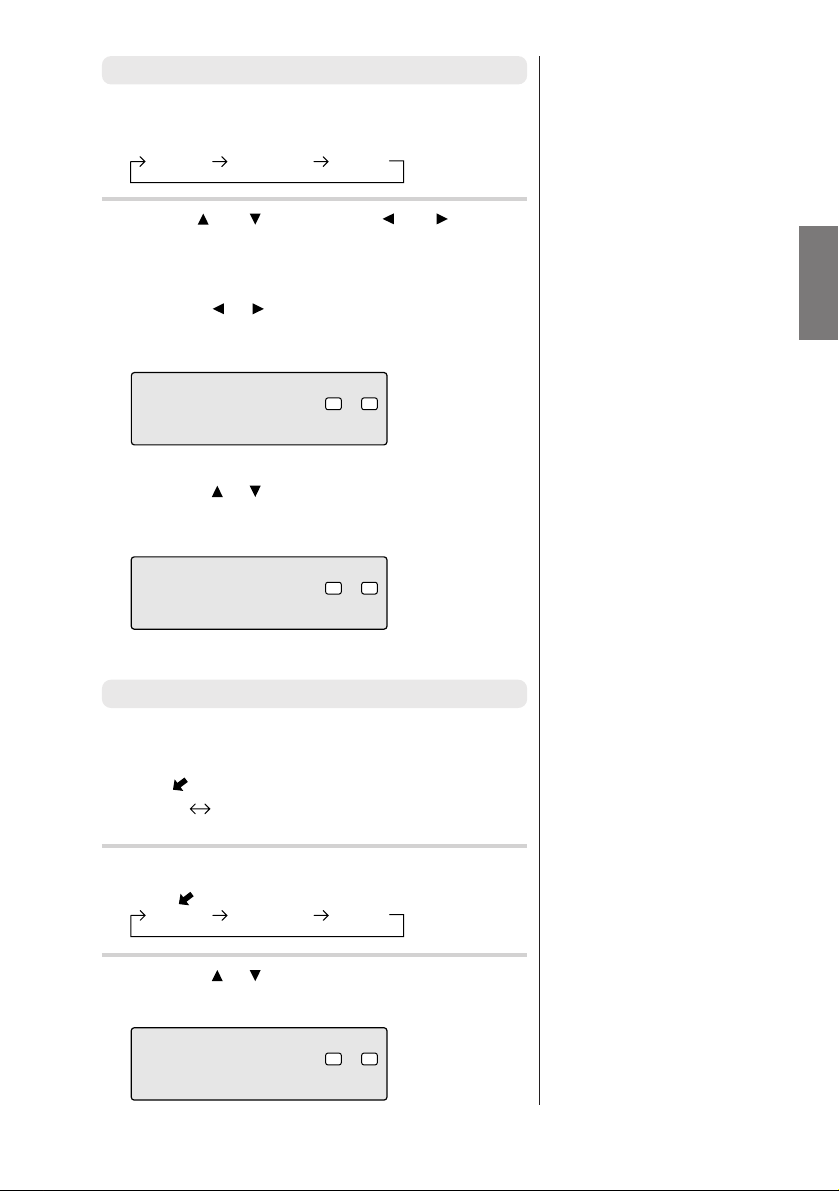
Adjusting the subwoofer
When Ai-NET connections are used, the volume, subwoofer,
balance and fader are adjusted from the head unit (they cannot be
adjusted from the PXA-H900). The subwoofer level only can be
adjusted from the PXA-H900 as well.
Press the MODE button for at least 2 seconds to
1
turn the “Sub Wf.” setting to “ON”.
Sub Wf.ONSub Wf.
Press the MODE button.
2
Press the
adjust.
The level can be adjusted between 0 and +15.
OFF
or button within 5 seconds to
ANALOG INPUT
Sub
Wf.
LR
+12
• The subwoofer cannot be
adjusted when the “Sub Wf.”
setting is set to “OFF”.
9-EN
Page 14
Basic Operation
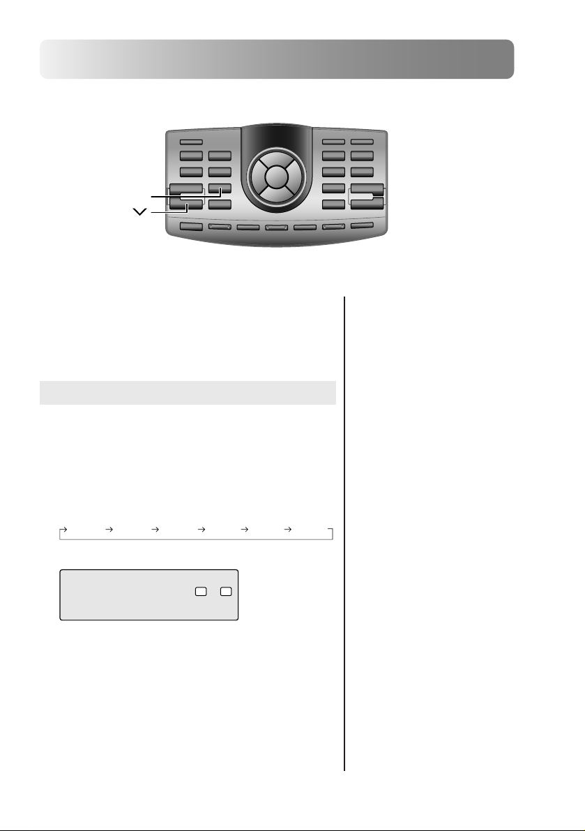
INPUT SELECT
VOL
Using with RCA-type or optical
cable connections
(non Ai-NET connections)
Switching the input
The PXA-H900 is equipped with three sets of analog signal inputs
and three sets of digital signal inputs.
Press the INPUT SELECT button to select the
1
input mode.
The sound of the selected mode is output.
DIGITAL1 DIGITAL2 DIGITAL3ANALOG1 ANALOG2 ANALOG3
ANAL OG INP UT
LR
Non Ai-NET connections
Alpine products are equipped for a
bus connection system called “AiNET” which can only be used for
connections between Ai-NET
products.
The PXA-H900 is an Ai-NET
product, but is designed to allow
connections to other (non Ai-NET)
products as well. Thus RCA-type
and optical cable connections are
also possible.
Connections to non Ai-NET
products are referred to as “non AiNET connections”.
10-EN
Page 15
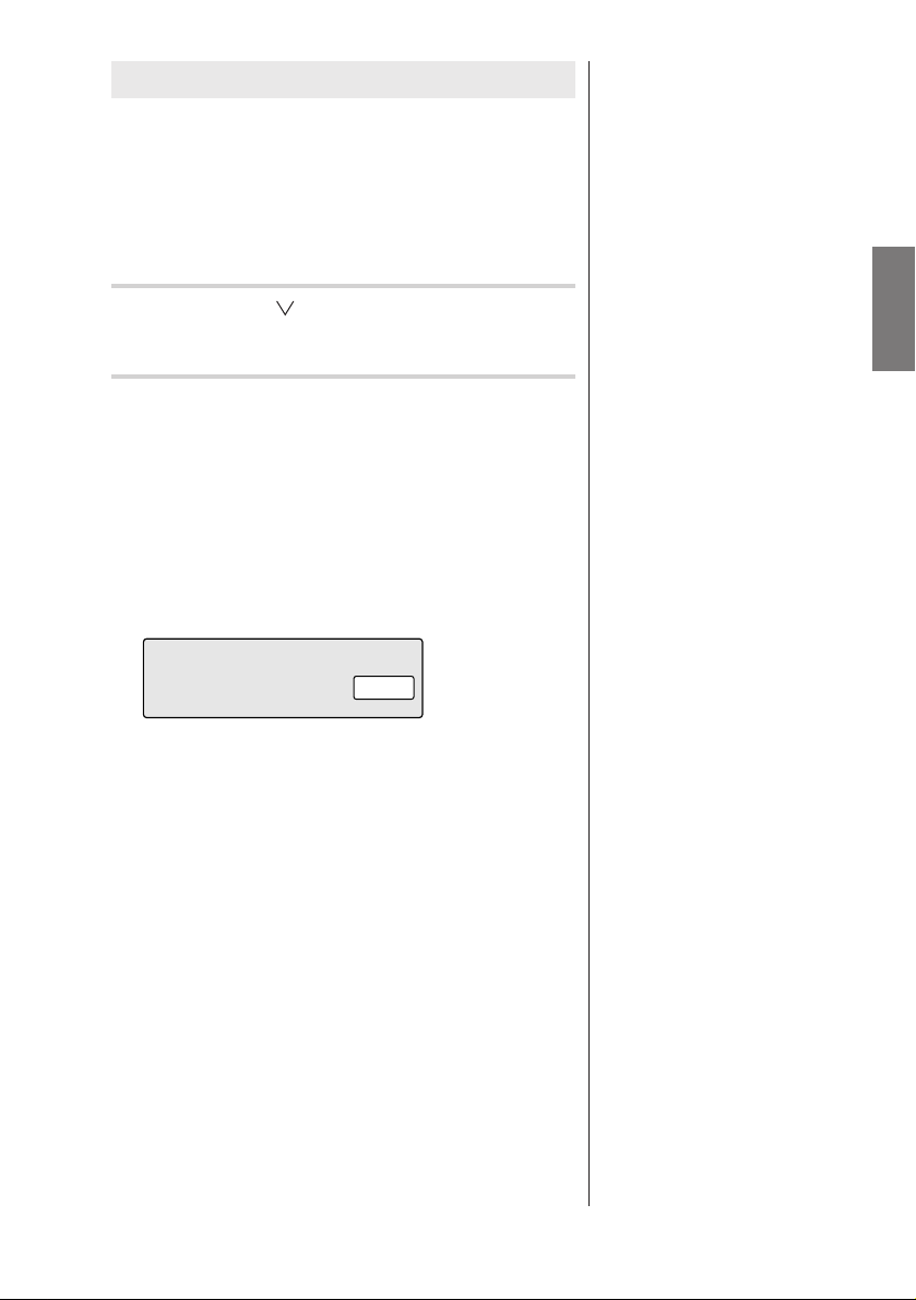
Adjusting the input level
Using the analog, RCA-type connections, the PXA-H900’s input
level must be preset from the head unit.
Adjust the input level using a sound source with a high recording
level (such as pops or rock music).
Turn on the head unit’s power.
1
Press the VOL button on the PXA-H900 and
2
set the volume level to “0”.
Gradually increase the volume of the head unit
3
until the “OVER” indicator appears in the display.
Reduce the volume slightly from this position,
until the OVER indicator just turns off. This
completes the setting. (The OVER indicator
should only flash momentarily while playing any
source.)
Do not change the head unit volume level from
this optimum setting. Use the PXA-H900, only, for
changing the volume level.
OVER
➔ next page
11-EN
Page 16
Basic Operation
,,
VOL
VOL
MODE
Using with RCA-type or optical
cable connections
(non Ai-NET connections)
Adjusting the volume, fader , balance
and subwoofer
After determining the input level, adjust the volume, fader,
balance and subwoofer from the PXA-H900. Be careful not to
make these adjustments on the head unit.
Adjusting the volume
Use the VOL and VOL buttons to adjust the
1
volume (from 0 to 35).
ANAL OG INP U T
VOLUME
LR
12
12-EN
Page 17
Adjusting the fader and balance
Press the MODE button and select the mode to
1
be adjusted.
BALANCE FADERSub Wf.
Use the and buttons or the and buttons
2
within 5 seconds to adjust to the desired level.
BALANCE:
Press the
the volume between the left and right speakers
(from L15 to R15).
or button to adjust the balance of
ANAL OG INP U T
BALANCE
LR
R3
FADER:
Press the
the volume between the front and back speakers
(from F15 to R15).
or button to adjust the balance of
ANAL OG INP U T
FADER
LR
L
F5
Adjusting the subwoofer
Press the MODE button for at least 2 seconds to
1
turn the “Sub Wf.” setting to “ON”.
Sub Wf.ONSub Wf.
Press the MODE button and select “Sub Wf.”.
2
Press the or button within 5 seconds to
3
adjust to the desired level (from 0 to +15).
OFF
BALANCE FADERSub Wf.
ANALOG INPUT
Sub
Wf.
LR
+12
13-EN
Page 18
Automatic Adjustments
Preparations for automatic
adjustments
The PXA-H900 is equipped with two automatic adjustment
functions: “Adaptive Equalizer” and “Precision Automated Time
Correction”.
The preparations described below must be made in order to
perform these automatic adjustments. After making these
preparations, refer to “Automatic adjustments (Adaptive
Equalizer)” (page 16) and “Performing time correction automatically (Precision Automated Time Correction)” (page 20) to
perform the respective automatic adjustments.
Check that the defeat mode is off.
1
(See page 53.)
Adjust the head unit and amplifier levels.
2
Head unit:
Set the balance and fader to “center”.
Front, rear and center amplifiers:
Set the amp gains to “center” or “normal” to start.
If there are no rear speakers, check that the rear
speakers are turned off. (See page 8.) Gain
levels may be changed if you are not satisfied
with the automatic results. Make the gain
changes and return the automatic adjustment.
Subwoofer amplifier:
Set the amplifier gain to “center” or “normal”. If
the subwoofer is located in the trunk or a remote
place (for example at the very back of a station
wagon), adjust the subwoofer to increase the
volume several steps.
Speaker Crossovers:
Set the crossovers for all the speakers in the
system that will require them. See page 32,
“Crossover adjustment”, for more information on
setting the crossovers.
• The adjustment differs according
to the position of the microphone. Search for the position at
which the desired sound quality
can be achieved.
• We recommend using speaker
boxes or box locations that
produce low levels of indirect
sound (for example, sealed boxes
or vented boxes with the vents
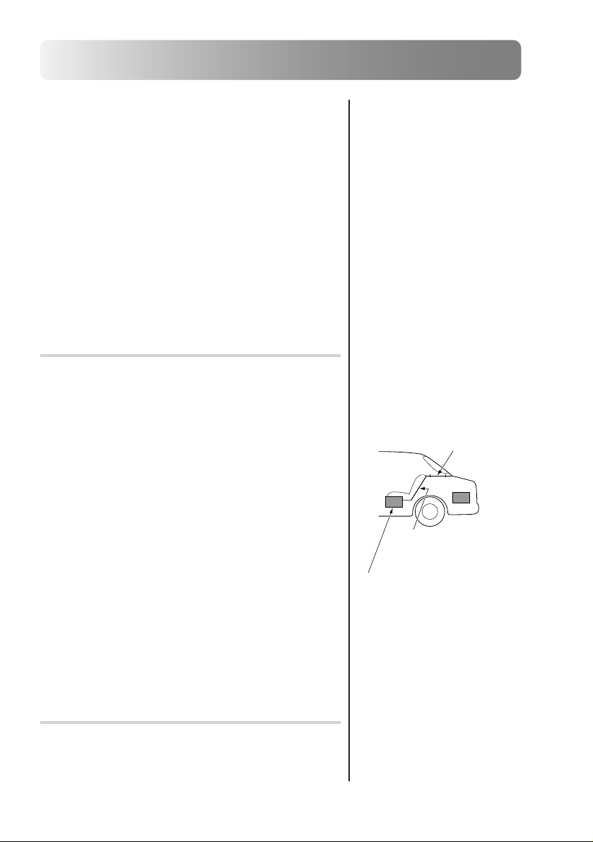
firing into the trunk).
• The proper adjustments cannot
be achieved if the subwoofer is
located in the trunk and the trunk
and cabin are separated by a
metal sheet. Either move the
subwoofer into the cabin or open
a hole in the rear tray to join the
two spaces. (This is not
necessary if the partition is not a
metal sheet.)
If the partition is a metal sheet,
open a hole in the rear tray.
If you encounter a problem,
consult your authorized dealer.
Is the partition a metal
sheet?
Or move the subwoofer into the
cabin.
Connect the included microphone to the PXA-
3
H900.
Refer to the Installation manual.
14-EN
• Do not disconnect the microphone during the automatic
adjustment procedure.
Page 19
Secure the microphone in place.
4
Failure to fix the microphone securely in place
may result in distortion or improper acoustic
positioning. The microphone must be mounted
very securely so the bass frequencies will not
vibrate it. For example, the microphone could be
wedged between the headrest and the seat. If the
microphone is placed on a tripod, the microphone
must be very securely mounted to the tripod (not
loosely clamped). The tripod must also be very
securely weighted and/or strapped so it cannot
move. The microphone would usually be placed
near the driver’s ear position. However, since the
Adaptive Equalizer is adjusting low frequencies,
the microphone does not need to be at the exact
ear position, it is more important that it is securely
mounted.
Hints for making the Adaptive Equalizer
adjustments
To achieve the desired acoustic image, we recommend fastening
the microphone to the four points described below. (The figures
are approximates. Adjust them according to the vehicle.)
A Ceiling directly above the listening position (driver’s seat
position – sharp sound)
B 20 cm (7-7/8") in front of above position (driver’s seat
position – softer sound than above, bass sound positioned toward front)
C 20 cm (7-7/8") further in front of above position (driver’s
seat position – even softer sound, bass sound positioned
further toward front)
D Base of rearview mirror (position for both driver’s and
passenger’s seats)
D
40cm(15-3/4")
C
20cm(7-7/8")
B
A
0
• The acoustic positioning changes
according to the position of the
microphone because the human
ear senses the distance from the
sound’s focal position. Adjust
according to your personal
tastes.
15-EN
Page 20
Automatic Adjustments
,
VOL
VOL
AUTO AEQ
Automatic adjustments
(Adaptive Equalizer)
Use this function to automatically perform frequency, phase and
time correction. Adjustments for the acoustic properties specific
to the vehicle’s interior are made to achieve the ideal acoustic
space.
Before starting the automatic adjustment proce-
1
dure, park the vehicle in a quiet place to avoid the
effects of external sounds.
Set the vehicle’s key to the ACC position.
2
Do not start the engine. The vibrations may
make it impossible to achieve the proper adjustment values.
• Preparations must be made
before performing the automatic
adjustment procedure. Refer to
page 14.
• The adjustments differ according
to the position of the microphone. We recommend
performing the operation
repeatedly with the microphone
in different positions. After each
operation, store the settings.
Compare the sound at the
different setting and from
different locations. Select the
one you prefer.
• The Adaptive Equalizer
eliminates or reduces the boomy
bass peaks common to the car
cabin. Elimination of the peaks
“uncovers” the lower bass
information which was masked
before. However, because your
ear and brain are used to those
peaks, the subwoofers may
sound less loud. You must listen
for a few weeks to allow your
ears and brain to recalibrate and
become used to the flat sound.
16-EN
Page 21

Adjust the volume.
3
• When using RCA-type connections, use the
PXA-H900’s VOL
and VOL buttons to
display “5” (on the PXA-H900’s display).
• When using Ai-NET connections, perform the
head unit’s volume operation to display “5” (on
the head unit’s display).
When the CDA-7990 is combined as a head
unit, adjust to “–50dB”.
Press the AUTO AEQ button.
4
Press the or button to select the channel or
5
speaker environment for outputting the correction
signals.
FRONT.ON SubWf. ON FRONT.ON SubWf. OFF FRONT.OFF SubWf. ON
AADAPTIVEEQUTO
F.ONS
PENTER]TOSTARTUSH [
U
b
LR
WON.RONT
• The Adaptive Equalizer flattens
the overall bass response, both
the SPL and the phase. Depending on how noisy your vehicle is,
a flat SPL response may cause
low bass notes to be masked by
road noise. In such cases, use the
conventional EQ features of the
PXA-H900 to gently “tilt up” the
low bass response. Again, listen
for a few weeks to allow your
ears and brain to recalibrate and
become used to the flat sound.
• After the automatic adjustments
are performed, the sound from
the different speakers arrives at
the listening position at virtually
the same time. If you are
accustomed to delays in the bass
sound (which is common with
conventional systems), the sound
may seem somewhat strange to
you. If so, increase the
subwoofer delay time slightly to
achieve sound closer to that of
home audio systems.
• Heavy bass speakers do not
reproduce medium low
frequencies (150 to 400 Hz) well
(the sound tends to be distorted).
When using such speakers, lower
the subwoofer’s cutoff frequency .
• If the volume of the subwoofer is
too low after the automatic
adjustment procedure is
performed, the adjustments have
not been performed properly.
Refer to step 2 under “Preparations for automatic adjustments”
and perform the adjustments
again.
• Depending on the speaker
settings (on or off), certain
speakers may not be displayed
(in which case they cannot be
set).
➔ next page
17-EN
Page 22

Automatic Adjustments
ENTER
AUTO AEQ
Press the ENTER button to set the automatic
6
adjustment mode, then leave the vehicle.
To cancel, press the AUTO AEQ button.
The automatic adjustment procedure consists of
the operations described below and requires 2 to
8 minutes to be completed.
Perform the time correction.
Perform the acoustic response measurement.
Perform the frequency response and phase
response corrections.
“ADJUSTMENTS ARE COMPLETED” is
displayed for about 5 seconds and the automatic adjustment mode is canceled.
Strong sounds (about 90 dB) are produced during
the automatic adjustment procedure. These
sounds can be heard outside the vehicle. Be
sure to park the vehicle in a place where the
sound will not be a nuisance.
• The time required to perform the
adjustments depends on the
speaker connections.
• The frequency response and
phase response corrections are
only applied to the front and
subwoofer channels.
Time correction is applied to all
channels.
• If processing is interrupted after
time correction is completed,
time correction is set to the
adjusted value.
• If the microphone does not pick
up the sound or the speakers are
not working or are connected or
wired improperly, the automatic
adjustments are not performed
and a warning message is
displayed.
Check the various speakers then
perform the automatic adjustments again.
Example of warning message
NOT IC E
PLEAS E
CHECK
AMP
LIFIER GAIN
AND CONNECTIONS
18-EN
Page 23

Check that the automatic adjustments have been
7
completed (that “ADJUSTMENTS ARE COMPLETED” has been displayed for 5 seconds), get
back in the vehicle, then disconnect the microphone.
To store the settings, refer to “Storing settings in
8
the memory” (page 52).
Turning the adjusted settings off
The adjusted settings can be turned off. Doing so clears the
settings, so we recommend storing them in the memory before
turning them off.
1)Press the AUT O AEQ button.
2)Press the button.
3)Press the ENTER button.
• Note that using for extended
periods of time without turning
on the engine may wear down the
battery.
19-EN
Page 24

Automatic Adjustments
VOL
VOL
AUTO TCR
Performing time correction
automatically
(Precision Automated Time
Correction)
Due to the particular conditions inside the vehicle, there is a
major difference between the distances of the various speakers
and the listening position. This function uses the included
measurement microphone to automatically measure and analyze
the distances between the speakers and the listening position and
perform the optimum time correction.
Before starting the automatic adjustment proce-
1
dure, park the vehicle in a quiet place to avoid the
effects of external sounds.
Set the vehicle’s key to the ACC position.
2
Do not start the engine. The vibrations may
make it impossible to achieve the proper adjustment values.
• Preparations must be made
before performing the automatic
adjustment procedure. Refer to
page 14.
• The PXA-H900’s automatic
adjustments take into account the
delay time between the time at
which the signals are input to the
speakers until the sound is
output. This does not correspond
to the actual distance.
• With the automatic adjustments,
the average delay time within the
speakers’ playable frequency
range is measured. Measurements may not be possible when
using special speakers or in
special playback environments.
If this is the case, perform the
adjustments manually.
20-EN
Page 25

Adjust the volume.
3
• When using RCA-type connections, use the
PXA-H900’s VOL
display “5” (on the PXA-H900’s display).
• When using Ai-NET connections, perform the
head unit’s volume operation to display “5” (on
the head unit’s display).
When the CDA-7990 is combined as a head
unit, adjust to “–50dB”.
Press the AUTO TCR button.
4
AIMECORRECTIONUTO T
PENTER]TOSTARTUSH [
and VOL buttons to
LR
➔ next page
21-EN
Page 26

Automatic Adjustments
ENTER
Press the ENTER button to set the automatic
5
adjustment mode, then leave the vehicle.
To cancel, press the AUTO TCR b utton.
The automatic adjustment procedure consists of
the operations described below and requires
about 2 minutes to be completed.
Perform the time correction.
AUTO TCR
“ADJUSTMENTS ARE COMPLETED” is
displayed for about 5 seconds and the automatic adjustment mode is canceled.
Strong sounds (about 90 dB) are produced during
the automatic adjustment procedure. These
sounds can be heard outside the vehicle. Be sure
to park the vehicle in a place where the sound will
not be a nuisance.
22-EN
• If the microphone does not pick
up the sound or the speakers are
not working or are connected or
wired improperly, the automatic
adjustments are not performed
and a warning message is
displayed.
Check the various speakers then
perform the automatic adjustments again.
Example of warning message
NOT IC E
PLEAS E
CHECK
AMP
LIFIER GAIN
AND CONNECTIONS
Page 27

Check that the automatic adjustments have been
6
completed (that “ADJUSTMENTS ARE COMPLETED” has been displayed for 5 seconds), get
back in the vehicle, then disconnect the microphone.
To store the settings, refer to “Storing settings in
7
the memory” (page 52).
• Note that using for extended
periods of time without turning
on the engine may wear down the
battery.
23-EN
Page 28

Settings/Adjustments
Performing time correction
manually (Time Correction)
Though sufficient correction can be achieved with the “Adaptive
Equalizer” and “Precision Automated Time Correction” automatic
adjustments, it is also possible for the user to calculate the
correction values and make the adjustments manually. This
manual adjustment requires sufficient knowledge and experience,
however, so we suggest you have it performed at your store of
purchase.
Check that the defeat mode is off.
1
(See page 53.)
Sit in the listening position (the driver’s seat, for
2
example) and measure the distance (in meters)
between your head and the various speakers.
Calculate the difference in distance between the
3
farthest speaker and the other speakers.
L = (distance of farthest speaker) –
(distance of other speakers)
• When the microphone is
connected, the sound in the car is
input through the microphone
and displayed on the spectrum
analyzer. This display can be
used as reference when making
the adjustment. For details of the
spectrum analyzer display, see
“Switching the display mode”
(page 53).
• This adjustment is easier when
test signals such as pink noise are
used. For information on test
signals, consult your store of
purchase.
Divide the distances calculated for the different
4
speakers by the speed of sound (340 m/s
temperature 14°C).
This value is the time correction value for the
different speakers.
24-EN
• The speed of sound fluctuates
according to the temperature.
The accurate speed of sound can
be achieved with the formula
shown below.
Speed of sound =
331.45 + C x T
C: 0.607
T: Temperature (°C)
Page 29

• Concrete examples
1. Calculating the time correction value for the front left speaker on the diagram below.
Conditions:
Distance between farthest speaker and listening position: 2.25 m (88-3/4")
Distance between front left speaker and listening position: 0.5 m (20")
Calculation: L = 2.25 m (88-3/4") – 0.5 m (20") = 1.75 m (68-3/4")
Compensation time = 1.75 ÷ 340 x 1000 = 5.1 (ms)
In other words, setting the time correction value for the front left speaker to 5.1 (ms) sets a
virtual distance matching the distance to the farthest speaker.
5.1ms
0.5m
★
(20")
2.25m
(88-3/4")
The sound is uneven because the distance
between the listening position and the
different speakers is different.
The difference in the distance between the
front left and rear right speakers is 1.75
meters (68-3/4").
★
Time correction eliminates the difference
between the time required for the sound
from the different speakers to reach the
listening position.
Setting the time correction of the front left
speaker to 5.1 ms makes it possible to
coordinate the distance from the listening
position to the speaker.
➔ next page
25-EN
Page 30

Settings/Adjustments
ENTER
Press the TCR button to set the time correction
5
mode.
Press the ch UP or ch DN button to select the
6
desired channel.
FLLOW FRLOW FRMID FLHIGHFLMID FRHIGH
REAR LREAR RCENTERSub Wf.LSub Wf.R
,,
TCR
ch UP
ch DN
Press the or button to adjust the time
7
correction value.
TRLOW5.1
CR F
()
L:0EVEL
[ms]
68. 3 173
[[icmnch ]
]/
[dB]
LR
26-EN
• Displayed distance
The values indicated for “inch”
and “cm” are the distance
calculated from the time.
(340 m/s temperature 14°C, 1
inch is calculated as 2.54 cm.)
• In reality the time difference
depends not only on the
difference in physical distance
but also on the delay time
between the time at which the
signals are input to the speakers
until the sound is output. This
delay time depends on the
speaker, and may also be
somewhat affected on how the
speaker is mounted on the
vehicle. After making the
setting, we recommend listening
to the sound and fine-adjusting if
necessary.
Page 31

Press the or button to adjust the speaker
8
output level.
The level can be set to “OFF” or adjusted be-
tween –12 and 0.
Press the ENTER button to complete the setting.
9
27-EN
Page 32

Settings/Adjustments
,,
ENTER
DISPLAY ON/OFF
ch UP
GEQ
ch DN
Equalizer adjustments
The level of the front, rear and center channels can be adjusted
separately for 31 bands and the subwoofer can be adjusted for 10
bands (a total of 175 bands) to achieve the desired sound field.
Check that the defeat mode is off.
1
(See page 53.)
Press the GEQ button.
2
Press the ch UP or ch DN button to select the
3
desired channel.
FRONT REAR CENTER Sub Wf.
• When the microphone is
connected, the sound in the car is
input through the microphone
and displayed on the spectrum
analyzer. This display can be
used as reference when making
the adjustment. For details of the
spectrum analyzer display, see
“Switching the display mode”
(page 53).
• This adjustment is easier when
test signals such as pink noise are
used. For information on test
signals, consult your store of
purchase.
• Even more subtle adjustments
can be used using a computer.
For details, consult your store of
purchase.
• Check the playable frequency
ranges of the connected speakers
before making the equalizer
adjustments. If the speaker’s
playable frequency range is 55
Hz to 30 kHz, for example,
adjusting the 40 Hz or 20 Hz
band has no effect. Additionally,
you may overload and damage
the speakers.
28-EN
Page 33

Press the or button so that the frequency
4
band is flashing.
Adjustable frequency bands
“FRONT”/“REAR”/“CENTER”: 20 Hz to 20 kHz
(in 1/3 octave steps)
“Sub Wf.”: 20 Hz to 160 Hz
(in 1/3 octave steps)
GRONT50.0EQ F
Press the or button to adjust to the desired
5
level (between ±9 dB in 1 dB steps).
[dB][Hz ]
0
LR
Repeat the above operation to adjust other
frequency bands.
• When adjusted with the Adaptive
Equalizer
• When adjusted with “FRONT.
ON” for the Adaptive
Equalizer adjustment,
frequencies of 500 Hz and
below GEQ FRONT cannot be
adjusted.
• When adjusted with “Sub Wf.
ON” for the Adaptive
Equalizer adjustment, GEQ
Sub Wf. cannot be adjusted.
GRONT50.0EQ F
Press the ENTER button to complete the setting.
6
[dB][Hz ]
5+
LR
Real time analyzer
When the microphone included with the PXA-H900 is connected,
the sounds inside the vehicle are input through the microphone
and displayed on the spectrum analyzer display.
1)With the microphone connected, press the DISPLAY ON/
OFF button and select the spectrum analyzer display
mode.
Operation
display
For details, refer to “Switching the display mode” (page 53).
Spectrum
analyzer
display
Display off
• Once the settings have been
made, we recommend storing
them in the memory. See page
52 for instructions.
• Real time analyzer
This is a function for displaying
the microphone input signals or
input signals on the spectrum
analyzer display. This allows the
signal properties or the acoustic
properties inside the vehicle
(amplitude) to be measured even
without special equipment.
When microphone connected:
Spectrum analyzer display of
acoustic properties inside the
vehicle
When microphone not connected:
Spectrum analyzer display of
input signals
29-EN
Page 34

Settings/Adjustments
Crossover network
The PXA-H900 is equipped with an active dividing network allowing the bands to be split before
amplification by the power amplifier.
Because of this, there is no need for a passive network between the speakers and amplifiers and the
amplifiers are fully independent, thus eliminating the problem of interference and making it possible to
achieve the optimum acoustic space by dividing the playback frequencies in a way suited to the capacities
of the speakers.
This adjustment requires sufficient knowledge and experience. If you have problems, so we suggest you
have the adjustment made by your store of purchase.
Adjust the high pass filter (H.P.F.) and low pass filter (L.P.F.) and set the slope (filter
response attenuation slope) for the different bands.
Make the adjustments according to the playable frequency ranges and frequency
responses of the connected speakers.
Cutoff frequency
adjustment range
(1/6 octave steps)
H.P.F. L.P.F. H.P.F. L.P.F.
Slope adjustment
FLOW
(Front low range speaker)
FMID
(Front mid range speaker)
FHIGH
(Front high range speaker)
REAR
(Rear speaker)
CENTER
(Center speaker)
Sub Wf.
(Subwoofer)
30-EN
20Hz –
18kHz
20Hz –
18kHz
1kHz –
18kHz
20Hz –
18kHz
20Hz –
18kHz
20Hz –
180Hz
22.5Hz –
20kHz
22.5Hz –
20kHz
1.1kHz –
20kHz
22.5Hz –
20kHz
22.5Hz –
20kHz
22.5Hz –
200Hz
-6/-12/-18/-24/-30dB/
Filter OFF
-6/-12/-18/-24/-30dB/
Filter OFF
-6/-12/-18/-24/-30dB -6/-12/-18/-24/-30dB/
-6/-12/-18/-24/-30dB/
Filter OFF
-6/-12/-18/-24/-30dB/
Filter OFF
-6/-12/-18/-24/-30dB/
Filter OFF
-6/-12/-18/-24/-30dB/
Filter OFF
-6/-12/-18/-24/-30dB/
Filter OFF
Filter OFF
-6/-12/-18/-24/-30dB/
Filter OFF
-6/-12/-18/-24/-30dB/
Filter OFF
-6/-12/-18/-24/-30dB
Page 35

Output signals with these frequencies
Slope adjustment
20Hz 10kHz
H.P.F. cutoff frequency
L.P.F. cutoff frequency
Slope off
The H.P.F. setting cannot be the same as or exceed the L.P.F. setting for that channel.
• The crossover network is a filter that divides specific frequency bands.
• The high pass filter is a filter that cuts frequencies below a certain frequency (bass frequencies) and lets
through treble frequencies.
• The low pass filter is a filter that cuts frequencies above a certain frequency (treble frequencies) and
lets through bass frequencies.
• The slope is a value expressing the attenuation of the signal in decibels when the frequency is increased
or decreased by one octave.
• The higher the slope value, the steeper the slope.
• If the slope is set to “OFF”, the signal does not pass through the filter, so there is no effect.
• In order to protect the speakers, the front high range high pass filter cannot be turned off (the slope
cannot be set to “OFF”).
For the same reason, the subwoofer low pass filter cannot be turned off (the slope cannot be set to
“OFF”).
• T weeters may be damaged if low frequency signals are input to them.
31-EN
Page 36

Settings/Adjustments
,,
ENTER
TCR
DIV
ch UP
ch DN
Crossover adjustment
Check that the defeat mode is off.
1
(See page 53.)
Press the DIV button to set the divider adjustment
2
mode.
Press the ch UP or ch DN button to select the
3
channel (speaker) to be adjusted.
FLOW FMID FHIGH REAR CENTER Sub Wf.
Press the or button to select the crossover
4
H.P.F. or L.P.F. band.
The selected band flashes.
DID400OFFIV FM
[Hz ]
LR
• If the Adaptive Equalizer
adjustment has been performed,
adjusting “FLOW” or “Sub Wf.”
has no effect since this is no
longer the Adaptive Equalizer
“DIV” setting.
A caution message appears on
the screen. Press the ENTER
button to continue the adjustment, ch UP or ch DN button to
cancel it.
32-EN
Page 37

Press the or button to select the desired
5
cutoff frequency (crossover point).
The bands that can be adjusted differ according
to the channel (speaker).
Adjust the slope by pressing the DIV button.
6
Repeat steps 3 to 6 to adjust the crossover point/
slope for other channels.
[Hz ]
DID280IV FM
Press the ENTER button to complete the setting.
7
Hint for adjusting the subwoofer
• If the subwoofer is installed on the rear deck, setting a
gentle L.P.F. slope (for example –6 dB/oct.) makes the
sound localization more to the rear. This can also affect
the acoustic localization of the front.
Hints for adjusting the high range
• Depending on the speaker, inputting low frequency
component signals (about 2 kHz or less) with the H.P.F.
adjustment could result in distortion. If so, set a steep
slope (for example –36 dB/oct.).
When doing so, adjust so that the mid and high range
sounds do not separate.
• Normally use with the L.P.F. off. If the high range is too
strong, we recommend adjusting for a gentle slope.
–12
[dB/ oct ]
LR
• The selected slope flashes.
• After making the settings, we
recommend storing them in the
memory. See page 52 for
instructions.
• Listen to the sound of the various
speakers and adjust the levels if
the balance is poor.
Adjusting the speaker output level
1) Press the TCR button.
2) Press the ch UP or ch DN button
to select the desired speaker.
3) Press the or button to adjust
the speaker output level. The
level can be set to “OFF” or
adjusted between –12 and 0.
4) Press the ENTER button.
Hint for adjusting the low range
• When a subwoofer is connected and you are using a
speaker with a low range of under 10 or 12 cm (3-15/16"
or 4-3/4"), setting the low range H.P.F. to “OFF” can result
in distortion when low frequency components are input.
If so, set the H.P.F. slope to a value suited for the
speaker’s frequency response.
33-EN
Page 38

Settings/Adjustments
,,
Switching the phase
The phase of the different speakers can be switched.
Set to the phase at which the sound from the speakers is clearest.
It is also possible to switch the subwoofer between stereo and
monaural.
Check that the defeat mode is off.
1
(See page 53.)
ch UP
ch DN
PHASE
Press the PHASE button.
2
Press the ch UP or ch DN button to select the
3
desired channel.
FLOW FMID FHIGH REAR CENTER Sub Wf.
34-EN
Page 39

Press the or button to switch the phase.
4
0° 180°
PHASE F LOW 180
[deg]
LR
Switching the subwoofer between
stereo and monaural
1)At step 3 above, select “Sub Wf.”.
2)Press the or button to switch between “ST” (stereo)
and “MONO” (monaural).
MONOST
35-EN
Page 40

Using Dolby Surround
PL / REAR FILL
Using the Pro Logic mode
With the PXA-H900, Pro Logic processing can be conducted on
the music signals recorded on two channels to achieve Dolby Pro
Logic surround sound. For two-channel Dolby Digital, DTS and
MPEG2 signals, there is also a “REAR FILL” function for
outputting the signals of the front channel to the rear channel.
Press the PL/REAR FILL button to select the
1
desired mode.
DOLBY PROLOGIC REAR FILL OFF
DOLBY D GITALI
DPL/REAARILLFOLBY
DOLBY P OROGICL
LR
S
• This function only works with
two-channel signals. This
operation cannot be performed
when 5.1-channel DTS or Dolby
Digital signals are input.
• “REAR FILL” function
Depending on the input signals,
the sound may only be output
from the front speakers. In this
case, the “REAR FILL” function
can be used to output signals
from the rear speakers as well.
• Once the settings are made, we
recommend storing them in the
memory. See page 52 for
instructions.
• When the “REAR FILL” mode is
turned on, sound may be
produced from the rear speakers
even if the rear speakers are set
to “OFF”. Do not use the
“REAR FILL” function if you do
not want to output sound from
the rear speakers.
• The HDCD decode mode cannot
be used in the “DOLBY
PROLOGIC” mode.
36-EN
Page 41

Adjustment procedure for Dolby Surround
Make the adjustments described below in order to reproduce Dolby Digital and DTS sound with greater
accuracy.
Adjustment procedure
Speaker setup (page 38)
(Turning the speakers to be used on and off and setting their response)
1
Adjusting the speaker levels (page 40)
(Adjusting the signal output level to the various speakers)
2
Center/rear speaker time correction (pages 42 and 44)
(Adjusting the signal output time compensation (timing) of the various speakers)
3
Adjusting the acoustic image (page 46)
(Adjusting the acoustic image to achieve a sound as if the center speaker were directly
4
in front of the listener)
Mixing bass sound to the rear channel (page 48)
(Achieving smooth sound in the rear seat by mixing the front audio signals with the
5
rear speaker signals)
Achieving powerful high volume sound (page 50)
(Achieving energetic sound with even greater power, like the sound in a movie theater)
6
Storing settings in the memory (page 52)
(Storing all the settings and adjustments made on the PXA-H900 (not only the above
7
settings/adjusts) in the memory)
Note: In case of combining the Automatic adjustments etc.
W e recommend to make the Automatic adjustments before the Dolby Surround adjustments.
37-EN
Page 42

Using Dolby Surround
,,
5.1 ch SETUP
ENTER
Speaker setup
The PXA-H900 can be set according to the playable frequency
range of your speakers.
Check the playable frequency range of the speakers (not including
the subwoofer) before performing this operation to verify whether
the speakers can play low frequencies (of about 80 Hz or less).
Press the 5.1ch SETUP button.
1
Press the or button and select “SPEAKER
2
SETUP”.
SPEAKER SETUP OUTPUTLEVEL SETUP
Press the ENTER button.
3
CENTER DELAY SETUPREAR DELAY SETUP
BI-PHANTOM SETUP
REAR-MIX SETUP
• This function can be set in the
Pro Logic, DTS, MPEG and
Dolby Digital modes.
• A void stopping, pausing,
switching the disc, cueing, fastforwarding or switching the
audio channel of the player while
making this adjustment. The
setting is canceled if the decode
mode is switched.
38-EN
Page 43

Press the or button and select the speakers
4
to be set.
FRONT REARCENTER
Press the or button and select the speaker
5
response.
SMALL OFFLARGE
2
*
1
*
SMALL:
When a speaker that cannot play low frequencies
(80 Hz or less) is connected
LARGE:
When a speaker that can play low frequencies
(80 Hz or less) is connected
OFF:
When no speaker is connected
• If the center speaker is turned
“OFF”, the center channel’s
audio signals are added to the
audio signals output from the
front speakers.
• If you set the speaker response to
“OFF”, also set the speaker level
adjustment (speaker setting) to
“OFF”. (See page 8.)
• *1 It is not possible to set the
front speakers to “OFF”.
• *2 If the front speakers are set to
“SMALL”, the rear and center
speakers cannot be set to
“LARGE”.
• Perform the setup for the all the
speakers (“FRONT”, “CENTER”
and “REAR”). If not, the sound
may not be balanced.
DOLBY D GITALI
AKER SE TU PSPE
FRONT LARGE
Press the 5.1ch SETUP button to complete the
6
setting.
LC
LFE
Ls Rs
R
To perform other setup operations, press the
ENTER button to display the setup menu.
• Once the settings are made, we
recommend storing them in the
memory. See page 52 for
instructions.
39-EN
Page 44

Using Dolby Surround
,
5.1 ch SETUP
ENTER
ch UP
ch DN
Adjusting the speaker levels
Use the test tones output from the PXA-H900 to adjust so that the
volume of the different speakers is equal.
To achieve a strong sense of presence, adjust so that the volume of
the sound heard from the different speakers at the listening
position is the same.
Press the 5.1ch SETUP button.
1
Press the or button and select “OUTPUT
2
LEVEL SETUP”.
SPEAKER SETUP OUTPUTLEVEL SETUP BI-PHANTOM SETUP
*
REAR DELAY SETUP
Not displayed when the rear/center speaker setting is set to
*
“OFF”.
Press the ENTER button. Test tones are output
3
from the various speaker channels in order for
CENTER DELAY SETUP
*
REAR-MIX SETUP
about 2 seconds each.
L (left front) C (center) R (right front)
RS (right surround)LS (left surround)
*
*
• This function can be set in the
Pro Logic, DTS, MPEG and
Dolby Digital modes.
• A void stopping, pausing,
switching the disc, cueing, fastforwarding or switching the
audio channel of the player while
making this adjustment. The
setting is canceled if the decode
mode is switched.
• If a speaker is set to the off
mode, that speaker’s level cannot
be adjusted.
Refer to “Speaker setup” (page
38).
40-EN
Page 45

While the test tones are being produced from the
4
speakers, press the
that the volume of the different speakers is equal.
The level of the different speakers can be
adjusted within a range of ±10 dB.
or button to adjust so
• Adjust based on the front
speakers.
TEST NO SIE
PUT LEVE L S ETUPOUT
FRONT L +2
L
Adjusting with the speaker fixed
1) Press the ch UP or ch DN button to select the
speaker to be adjusted.
2) Press the
3) Repeat steps 1) and 2) to adjust, then press the
ENTER button.
4) To complete the adjustment, press the 5.1ch
SETUP button.
Press the 5.1ch SETUP button to complete the
5
adjustment.
To perform other setup operations, press the
ENTER button to display the setup menu.
or button to adjust the volume.
• Once the settings are made, we
recommend storing them in the
memory. See page 52 for
instructions.
41-EN
Page 46

Using Dolby Surround
,
5.1 ch SETUP
ENTER
Center speaker time correction
Use this function after adjusting the delay time of the different
speakers with the “Adaptive Equalizer”, “Precision Automated
Time Correction” and “automatic/manual time compensation”
functions. Using this function results in sound with a sense of
presence.
Press the 5.1ch SETUP button.
1
Press the or button and select “CENTER
2
DELAY SETUP”.
SPEAKER SETUP OUTPUTLEVEL SETUP
*
REAR DELAY SETUP
Not displayed when the rear/center speaker setting is set to
*
“OFF”.
(See page 38.)
CENTER DELAY SETUP
BI-PHANTOM SETUP
*
REAR-MIX SETUP
• This function can be set in the
• A void stopping, pausing,
*
*
Pro Logic, DTS, MPEG and
Dolby Digital modes.
switching the disc, cueing, fastforwarding or switching the
audio channel of the player while
making this adjustment. The
setting is canceled if the decode
mode is switched.
42-EN
Page 47

Press the ENTER button.
3
Press the or button to adjust the time correc-
4
tion value.
The center delay setting can be adjusted within
the range of 0 to 5 ms.
DOLBY
DGITALI
CRENTE
Press the 5.1ch SETUP button to complete the
5
adjustment.
DEL AY
SETUP
3
LC
LFE
Ls Rs
R
To perform other setup operations, press the
ENTER button to display the setup menu.
• This adjustment cannot be
performed when the center
speaker setup setting is set to
“OFF”.
• If the distance of the front
speaker is shorter than or the
same as that of the center
speaker, set to “0”. If the
distance of the front speaker is
longer, set to 1 to 5.
• Once the settings are made, we
recommend storing them in the
memory. See page 52 for
instructions.
43-EN
Page 48

Using Dolby Surround
,
5.1 ch SETUP
ENTER
Rear speaker time correction
Perform this function after adjusting the delay time of the various
speakers.
Adding this time correction to the values adjusted with the
“Adaptive Equalizer”, “Precision Automated Time Correction”
and “automatic/manual time compensation” functions gives the
sound a sense of expansion.
Press the 5.1ch SETUP button.
1
Press the or button and select “REAR DELAY
2
SETUP”.
SPEAKER SETUP OUTPUTLEVEL SETUP
*
REAR DELAY SETUP
Not displayed when the rear/center speaker setting is set to
*
“OFF”.
(See page 38.)
Press the ENTER button.
3
CENTER DELAY SETUP
BI-PHANTOM SETUP
*
REAR-MIX SETUP
*
*
• This function can be set in the
Pro Logic, DTS, MPEG and
Dolby Digital modes.
• A void stopping, pausing,
switching the disc, cueing, fastforwarding or switching the
audio channel of the player while
making this adjustment. The
setting is canceled if the decode
mode is switched.
44-EN
Page 49

Press the or button to adjust the time correc-
4
tion value.
When the Pro Logic mode is off:
0: 0ms, 1: 5ms, 2: 10ms, 3: 15ms
When the Pro Logic mode is on:
0: 15ms, 1: 20ms, 2: 25ms, 3: 30ms
DOLBY
RREA
DEL AY
DGITALI
SETUP
3
LC
LFE
Ls Rs
R
• This adjustment cannot be
performed when the rear speaker
mode setting is set to “OFF”.
• If the distance of the front
speaker is shorter than or the
same as that of the center
speaker, set to “0”. If the
distance of the front speaker is
longer, set to 1 to 3.
Press the 5.1ch SETUP button to complete the
5
adjustment.
To perform other setup operations, press the
ENTER button to display the setup menu.
• Once the settings are made, we
recommend storing them in the
memory. See page 52 for
instructions.
45-EN
Page 50

Using Dolby Surround
,
,
5.1 ch SETUP
ENTER
Adjusting the acoustic image
To achieve sound with a sense of presence, the center speaker
must be placed directly in front of the listening position. With
this function, the center channel information is distributed to the
left and right speakers. This creates an acoustic images simulating
a center speaker directly in front of the listener.
Press the 5.1ch SETUP button.
1
Press the or button and select “BI-PHANTOM
2
SETUP”.
SPEAKER SETUP OUTPUTLEVEL SETUP BI-PHANTOM SETUP
*
REAR DELAY SETUP
Not displayed when the rear/center speaker setting is set to
*
“OFF”.
(See page 38.)
Press the ENTER button.
3
CENTER DELAY SETUP
*
REAR-MIX SETUP
*
*
• This function can be set in the
Pro Logic, DTS, MPEG and
Dolby Digital modes.
• A void stopping, pausing,
switching the disc, cueing, fastforwarding or switching the
audio channel of the player while
making this adjustment. The
setting is canceled if the decode
mode is switched.
46-EN
Page 51

Press the or button to select “ON”.
4
0 OFF
(ON)
Press the or button to adjust the level.
5
The level can be adjusted within the range of –5
to +5. The higher the level, the more the position
of the center speaker is shifted to the sides.
DOLBY
–
P
HBI
ANT OM
DGITALI
SETUP
3+
LC
LFE
Ls Rs
R
• This adjustment cannot be
performed when the center
speaker setup setting is set to
“OFF”.
• The off mode is set automatically
when the center speaker setup
setting is set to “OFF”.
Press the 5.1ch SETUP button to complete the
6
adjustment.
To perform other setup operations, press the
ENTER button to display the setup menu.
• Once the settings are made, we
recommend storing them in the
memory. See page 52 for
instructions.
47-EN
Page 52

Using Dolby Surround
,
,
5.1 ch SETUP
ENTER
Mixing bass sound to the rear
channel
This function mixes the front channel audio signals to the audio
signals output from the rear speakers, improving the sound in the
vehicle’s rear seat.
Press the 5.1ch SETUP button.
1
Press the or button and select “REAR-MIX
2
SETUP”.
SPEAKER SETUP OUTPUTLEVEL SETUP
*
REAR DELAY SETUP
Not displayed when the rear/center speaker setting is set to
*
“OFF”.
(See page 38.)
Press the ENTER button.
3
CENTER DELAY SETUP
BI-PHANTOM SETUP
*
REAR-MIX SETUP
*
*
• This function can be set in the
Pro Logic, DTS, MPEG and
Dolby Digital modes.
• A void stopping, pausing,
switching the disc, cueing, fastforwarding or switching the
audio channel of the player while
making this adjustment. The
setting is canceled if the decode
mode is switched.
48-EN
Page 53

Press the or button to select “ON”.
4
0 OFF
(ON)
• This adjustment cannot be
performed when the rear speaker
setup setting is set to “OFF”.
• The off mode is set automatically
when the rear speaker setup
setting is set to “OFF”.
• When the “REAR-MIX”
function is turned “ON”, sound
may be produced from the rear
speakers even if the rear speakers
are set to “OFF”. If you do not
want sound to be produced from
the rear speakers, turn the
“REAR-MIX” mode “OFF”.
Press the or button to adjust the level.
5
The level can be set to one of five positions:
–6, –3, 0, +3, and +6. The higher the level, the
more the bass sound output from the rear
speakers. (The effect differs according to the
software (DVD, etc.).)
DOLBY D GITALI
RREA
MIX
–
SETUP
3+
Press the 5.1ch SETUP button to complete the
6
adjustment.
LC
LFE
Ls Rs
R
To perform other setup operations, press the
ENTER button to display the setup menu.
• If the “REAR-MIX” adjustment
is performed when the “REAR
FILL” function is on, during the
2-channel decode mode the
“REAR FILL” function is given
priority, so the sound does not
change as adjusted with the
“REAR-MIX” function.
• Once the settings are made, we
recommend storing them in the
memory. See page 52 for
instructions.
49-EN
Page 54

Using Dolby Surround
,
NAV. MIX
LISTENING MODE
ENTER
Achieving powerful high
volume sound
,
With Dolby Digital, the dynamic range is compressed so that
powerful sound can be achieved at regular volume levels. This
compression can be canceled to achieve an energetic sound with
even greater power, like the sound in a movie theater.
Press the LISTENING MODE button and select
1
the “MAXIMUM” mode.
STANDARD MAXIMUM
STANDARD:
For powerful sound at regular volume levels
MAXIMUM:
For powerful sound at high volumes
DOLBY D GITALI
TLIS
NING
E
MODE
AXIMUMM
Press the ENTER button to complete the setting.
2
LC
LFE
Ls Rs
R
• This function works only in the
Dolby Digital mode.
• Keep the volume to a level at
which sounds outside the vehicle
can still be heard.
• This function may have no ef fect,
depending on the type of
software (DVD, etc.).
Once the settings are made, we
•
recommend storing them in the
memory. See page 52 for
instructions.
50-EN
Page 55

Convenient Functions
Navigation system voice
guidance interruption
When a navigation system is connected, this setting makes it
possible for the system’s voice guidance messages to interrupt the
sound of the PXA-H900.
It is also possible to set the audio volume level during voice
guidance message interruptions.
Press the NAV. MIX button.
1
Press the or button and select the mode.
2
VOICE GUIDANCE AUDIO ATT.
Press the or button to adjust the volume
3
level.
VOICE GUIDANCE:
OFF and 1 to 7 (navigation system voice guidance message volume level)
AUDIO ATT.:
0 to 7 (Audio attenuation level during navigation
system voice guidance interruptions)
• This function does not work
when no center speaker is
connected.
For details, refer to the Installation manual.
DOLBY D GITALI
–
MIX
ANVI
VGUIADNCE 4OICE
Press the ENTER button to complete the setting.
4
LC
LFE
Ls Rs
R
51-EN
Page 56

Convenient Functions
P1~P6
DISPLAY ON/OFF
DEFEAT
Storing settings in the memory
The PXA-H900 includes six memories in which all the current
adjustments and settings can be stored.
Make the adjustments and settings you wish to
1
store in the memory.
Press and hold any of buttons P1 to P6 for at
2
least 2 seconds.
Within 5 seconds, press the button (P1 to P6) at
3
which you want to store the values.
PTMEMORYSAVERESE
CT PRESE No.TSELE
P1 TO P6
LR
C
LFE
Ls Rs
• Release the PXA-H900’s
• Approximately 5 seconds are
• The operations “Storing settings
Calling out stored values
Press the P1 to P6 button to select the number
1
(“MEMORY1” to “MEMORY6”) you wish to call
out.
Approximately 3 seconds are required to call out
the stored values.
• The display flashes while the
MEMORY LOCK switch (set it
to the left side) when you wish to
store settings.
For instructions on using the
MEMORY LOCK switch, refer
to the installation manual.
MEMORY
LOCK
required for memory processing.
in the memory” and “Calling out
stored values” are effective only
when the defeat is off.
values are being called out.
52-EN
DOLBY D GITALI
LNGINMEMMOYRODAI
P–2
LR
C
LFE
Ls Rs
Page 57

Defeat mode
Press the DEFEA T button.
1
All the settings become flat.
AGINPUTDEEFATNALO
To cancel, press the DEFEAT button again.
2
LR
“DEFEAT” appears.
Switching the display mode
Press the DISPLAY ON/OFF button to select the
1
desired display mode.
Operation
display
DOLB Y D GI TALI
Operation display
Spectrum
analyzer
display
DIGI TAL
P–3
LC
LFE
Ls Rs
Display off
R
• When the defeat mode is turned
on, none of the Adaptive
Equalizer, Precision Automated
Time Correction, T ime Correction, phase switching, equalizer
adjustment, crossover network,
memory or memory recall
operations can be performed.
• To protect the speakers, the
crossover network settings do not
change.
• Press the VOL or INPUT
SELECT button in the Display
off mode to display for a few
seconds.
DOLB Y D GI TALI
Spectrum analyzer display
Display off
P–3
LC
LFE
Ls Rs
R
53-EN
Page 58

Convenient Functions
DTS
Switching the indicator color
(for non Ai-NET connections
only)
Press and hold the DISPLAY button for at least 2
1
seconds to select the desired indicator color.
Select blue or green.
DISPLAY
Indicator
DTS
Normally the PXA-H900 automatically identifies DTS signals so
there is no need to perform any particular operation to output DTS
signals.
If for some reason the DTS input signals cannot be identified,
perform the operation described below.
Press the DTS button.
1
To cancel, press the DTS button again.
2
54-EN
• Check whether the disc contains
DTS signals.
• If the DTS button is pressed
while no DTS signals are being
input, in some cases the sound
will be turned off.
• DTS is the abbreviation for
Digital Theater Systems.
Page 59

Information
Terminology
Dolby Digital
Dolby Digital is a digital audio compression
technology developed by Dolby Laboratories
that allows large quantities of audio data to be
efficiently recorded on discs. It is compatible
with audio signals from mono (1 channel) all
the way up to 5.1-channel surround sound.
The signals for the different channels are
completely independent, and since the sound
is high quality digital there is no loss of sound
quality.
Center
speaker
Front
speakers
Rear
speakers
Subwoofer
Speaker layout for enjoying
Dolby Digital sound/DTS sound
Dolby Pro Logic
Dolby Pro Logic is the technology used to
decode programs encoded in Dolby Surround.
Pro Logic decoding will provide you with four
channels of sound (front left/right, center and
monaural rear surround) from a 2-channel
(stereo) source.
HDCD® (
®
, High Definition
Compatible Digital®)
Normally, the signals on music CDs use 16-bit
digitization. Discs mastered with HDCD,
however, contain data equivalent to 20 bits.
This set is equipped with an HDCD decoder.
When HDCD decoder compatible discs are
played, the sound is reproduced with a sense
of expansion and quality near that of the
original sound.
HDCD Equipped Car Audio
Your Alpine Car Audio PXA-H900 is equipped
with HDCD playback technology which
improves the audio fidelity of all CDs. Please
note that HDCD playback decoding will
increase the dynamic range of some CD
tracks recorded with the HDCD process,
which may cause their average level to sound
quieter than some other CD tracks.
®
, HDCD®, High Definition Compatible
Digital® and Pacific Microsonics™ are either
registered trademarks or trademarks of Pacific
Microsonics, Inc. in the United States and/or
other countries. HDCD system manufactured
under license from Pacific Microsonics, Inc.
DTS
This is a home-use digital sound format of the
DTS Sound System. This is a high quality
sound system, developed by Digital Theater
Systems Corp for use in movie theaters.
DTS has six independent sound tracks. The
theater presentation is fully realized in the
home and other settings. DTS is the abbreviation for Digital Theater Systems.
–B
55-EN
Page 60

Information
In case of difficulty
If you encounter a problem, please review
the items in the following checklist. This
guide will help you isolate the problem if the
unit is at fault. Otherwise, make sure the rest
of your system is properly connected or
consult your authorized Alpine dealer.
Set does not operate.
Nothing appears on the display.
• Vehicle’s ignition key is turned off.
- Turn the vehicle’s ignition key on.
• Set’s power is not turned on.
- Turn the vehicle’s ignition key on then
turn on the power of the head unit.
• Power cord is not securely connected.
- Connect the power cord securely.
• Fuse is blown.
- Replace with a fuse of the specified
capacity.
• Display mode is set to off.
- Switch the display to another mode.
(Page 53)
Power is on but no sound is
produced.
• Volume level is set to the minimum.
- Increase the volume level. (Page 12)
• Input mode is set to a mode to which
nothing is connected.
- Set to a connected mode. (Page 10)
• DTS mode is turned on though no DTS
signals are being input.
- Turn the DTS mode off. (Page 54)
No sound is produced from the
speakers.
• Cords are not securely connected.
- Connect the cords securely.
• Speaker is set to the off mode.
- Set the speaker to the on mode. (Pages 8
and 38)
• Subwoofer is turned of f.
- Turn the subwoofer on. (Pages 9 and 13)
Dolby Surround adjustments
cannot be made.
• No Dolby Digital, DTS or MPEG signals
are being input.
- Input Dolby Digital, DTS or MPEG
signals.
• Pro Logic mode is turned off.
- Set the Pro Logic mode to “DOLBY
PROLOGIC”. (Page 36)
Speaker setup settings cannot be
made.
• Front speakers are set to “SMALL”.
- Set the front speakers to “LARGE”.
(Page 38)
56-EN
Page 61

Speaker level cannot be adjusted.
• Speaker is set to the off mode.
- Set the speaker to the on mode. (Pages 8
and 38)
Speaker time correction cannot be
set.
• Speaker is set to the off mode.
- Set the speaker to the on mode. (Pages 8
and 38)
Center speaker’s acoustic image
cannot be adjusted.
• Speaker is set to the off mode.
- Set the speaker to the on mode. (Pages 8
and 38)
Sound cannot be mixed with the
rear channel.
• Speaker is set to the off mode.
- Set the speaker to the on mode. (Pages 8
and 38)
Caution when connecting the
DVA-5205/DVA-5200
Although the DVA-5205 and DVA-5200
provide adjustment screens for Parametric
Equalizer and Sound, these do not apply to
the PXA-H900.
57-EN
Page 62

Specifications
EQ number of bands: Front: 31
Rear: 31
Center: 31
Subwoofer: 10
Graphic equalizer boost cut
range: ±9 dB
Time correction control
range: 0 to 20 ms (0.1 ms steps)
Frequency response: 20 Hz to 20 kHz
S/N ratio: 110 dB
Channel separation: 80 dB
Input sensitivity: 850 mA (2V for analog 1 only)
Subwoofer crossover: 20 to 200 Hz (1/6 oct. steps)
Subwoofer level control: 0 dB to +15 dB
Rated output: 4V (with 10 k ohms load)
Input impedance: 10 k ohms or greater
Output impedance: 1 k ohm or less
Weight: Display unit 180 g (6 oz)
Remote control unit 140 g (5 oz)
(not including batteries)
Base unit 5.1 kg (11 lbs. 4 oz)
Dimensions
Display unit
Width 170 mm (6-3/4")
Height 46 mm (1-13/16")
Depth 24.6 mm (1")
Remote control unit
Width 144.7 mm (5-3/4")
Height 30.7 mm (1-3/16")
Depth 80 mm (3-1/8")
Base unit
Width 325 mm (12-25/32")
Height 69 mm (2-3/4")
Depth 280 mm (11")
<Components>
Parts name Quantity
Parts for mounting................ 1set
Owner’s manual ................... 1set
Remote control unit/holder .. 1set
Batteries (AAA) ........................ 4
Microphone/stand ................ 1set
Due to continuous product improvement, specifications and design are subject to change
without notice.
The illustrations included in these instructions may appear different from the actual product
due to printing conditions.
58-EN
Page 63

Manufactured under license from Dolby Laboratories. “Dolby”, “Pro Logic” and the doubleD symbol are trademarks of Dolby Laboratories. Confidential unpublished works. ©19921997 Dolby Laboratories. All rights reserved.
®
, HDCD®, High Definition Compatible Digital® and Pacific Microsonics™ are either
registered trademarks or trademarks of Pacific Microsonics, Inc. in the United States and/or
other countries. HDCD system manufactured under license from Pacific Microsonics, Inc.
This product is covered by one or more of the following: In the USA: 5,479,168, 5,638,074,
5,640,161, 5,808,574, 5,838,274, 5,854,600, 5,864,311, 5,872,531, and in Australia: 669114.
Other patents pending.
Manufactured under license from Digital Theater Systems, Inc. US Pat. No. 5,451,942 and
other worldwide patents issues and pending. “DTS” and “DTS Digital Surround” are trademarks of Digital Theater Systems, Inc. © 1996 Digital Theater Systems, Inc. All rights
reserved.
59-EN
Page 64

LIMITED WARRANTY
ALPINE ELECTRONICS OF AMERICA, INC. AND ALPINE OF CANADA INC. ("Alpine"), are dedicated to
quality craftsmanship and are pleased to offer this Warranty. We suggest that you read it thoroughly. Should
you have any questions, please contact your Dealer or Alpine at one of the telephone numbers listed below.
●
PRODUCTS COVERED:
This Warranty covers Car Audio/Visual Products
and Related Accessories ("the product"). Products
purchased in the Canada are covered only in the
Canada. Products purchased in the U.S.A. are
covered only in the U.S.A.
●
LENGTH OF WARRANTY:
This Warranty is in effect for one year from the date
of the first consumer purchase.
●
LIFETIME TAPE HEAD WARRANTY:
All Alpine Car Audio analog tape heads excluding
Video tape heads are warranted for life against
manufacturing defects causing failure.
●
WHO IS COVERED:
This Warranty only covers the original purchaser of
the product, who must reside in the United States,
Puerto Rico or Canada.
●
WHAT IS COVERED:
This Warranty covers defects in materials or
workmanship (parts and labor) in the product.
●
WHAT IS NOT COVERED:
This Warranty does not cover the following:
Damage occurring during shipment of the
1
product to Alpine for repair (claims must be
presented to the carrier).
Damage caused by accident, abuse, negligence,
2
misuse, improper connections, improper
operation or failure to follow instructions
contained in the Owner's manual.
Damage caused by act of God, including without
3
limitation, earthquake, fire, flood, storms or other
acts of nature.
Any cost or expense related to the removal or
4
reinstallation of the product.
Service performed by an unauthorized person,
5
company or association.
Any product which has the serial number
6
defaced, altered or removed.
Any product which has been adjusted, altered or
7
modified without Alpine's consent.
Any product not distributed by Alpine within the
8
United States, Puerto Rico or Canada.
Any product not purchased from an Authorized
9
Alpine Dealer.
Any product that has been determined to contain
p
an excessive amount of dust or dirt and any
product that contains other contaminants
including liquid or foreign objects.
●
HOW TO OBTAIN WARRANTY SERVICE:
You are responsible for delivery of the product to
1
an Authorized Alpine Service Center or Alpine
for repair and for payment of any initial shipping
charges. Alpine will, at its option, repair or
replace the product with a new or reconditioned
product without charge. If the repairs are
covered by the warranty, and if the product was
shipped to an Authorized Alpine Service Center
or Alpine, Alpine will pay the return shipping
charges.
Alpine Electronics of America, Inc., 19145 Gramercy Place, Torrance, California 90501, U.S.A.
Alpine Electronics of Canada, Inc., Suite 203, 7300 Warden Ave. Markham, Ontario, L3R 9Z6, Canada
You should provide a detailed description of the
2
problem(s) for which service is required.
You must supply proof of your purchase of the
3
product.
You must package the product securely to avoid
4
damage during shipment.
●
HOW WE LIMIT IMPLIED WARRANTIES:
ANY IMPLIED WARRANTIES INCLUDING
FITNESS FOR USE AND MERCHANTABILITY
ARE LIMITED IN DURATION TO THE PERIOD OF
THE EXPRESS WARRANTY SET FORTH ABOVE
AND NO PERSON IS AUTHORIZED TO ASSUME
FOR ALPINE ANY OTHER LIABILITY IN
CONNECTION WITH THE SALE OF THE
PRODUCT.
●
HOW WE EXCLUDE CERTAIN DAMAGES:
ALPINE EXPRESSLY DISCLAIMS LIABILITY FOR
INCIDENTAL AND CONSEQUENTIAL DAMAGES
CAUSED BY THE PRODUCT. THE TERM
"INCIDENTAL DAMAGES" REFERS TO
EXPENSES OF TRANSPORTING THE PRODUCT
TO THE ALPINE SERVICE CENTER, LOSS OF
THE ORIGINAL PURCHASER'S TIME, LOSS OF
THE USE OF THE PRODUCT, BUS FARES, CAR
RENTALS OR OTHERS COSTS RELATING TO
THE CARE AND CUSTODY OF THE PRODUCT.
THE TERM "CONSEQUENTIAL DAMAGES"
REFERS TO THE COST OF REPAIRING OR
REPLACING OTHER PROPERTY WHICH IS
DAMAGED WHEN THIS PRODUCT DOES NOT
WORK PROPERLY. THE REMEDIES PROVIDED
UNDER THIS WARRANTY ARE EXCLUSIVE AND
IN LIEU OF ALL OTHERS.
● HOW STATE/PROVINCIAL LAW RELATES TO
THE WARRANTY:
This Warranty gives you specific legal rights, and
you may also have other rights which vary form
state to state and province to province. In addition,
some states/provinces do not allow limitations on
how long an implied warranty lasts, and some do not
allow the exclusion or limitation of incidental or
consequential damages. Accordingly, limitations as
to these matters contained herein may not apply to
you.
●
IN CANADA ONLY:
This Warranty is not valid unless your Alpine car
audio product has been installed in your vehicle by
an Authorized Installation Center, and this warranty
stamped upon installation by the installation center.
●
HOW TO CONTACT CUSTOMER SERVICE:
Should the product require service, please call the
following number for your nearest Authorized Alpine
Service Center.
U.S.A. 1-800-ALPINE-1 (1-800-257-4631)
CANADA 1-800-ALPINE-1 (1-800-257-4631)
Page 65

Page 66

ALPINE ELECTRONICS, INC.
Tokyo office: 1-1-8 Nishi Gotanda,
Shinagawa-ku, Tokyo 141-8501, Japan
Tel.: (03) 3494-1101
ALPINE ELECTRONICS OF AMERICA, INC.
19145 Gramercy Place, Torrance,
California 90501, U.S.A.
Tel.: 1-800-ALPINE-1 (1-800-257-4631)
ALPINE ELECTRONICS OF CANADA, INC.
Suite 203, 7300 Warden Ave. Markham,
Ontario L3R 9Z6, Canada
Tel.: 1-800-ALPINE-1 (1-800-257-4631)
ALPINE ELECTRONICS OF AUSTRALIA PTY. LTD.
6-8 Fiveways Boulevarde Keysborough,
Victoria 3173, Australia
Tel.: (03) 9769-0000
ALPINE ELECTRONICS GmbH
Kreuzerkamp 7-11 40878 Ratingen,
Germany
Tel.: 02102-45 50
ALPINE ITALIA S.p.A.
Via C. Colombo 8, 20090 Trezzano Sul
Naviglio MI, Italy
Tel.: 02-48 47 81
ALPINE ELECTRONICS FRANCE S.A.R.L.
(RCS PONTOISE B 338 101 280)
98, Rue De La Belle Etoile, Z.I. Paris Nord II
B.P. 50016 F-95945, Roissy,
Charles de Gaulle Cedex, France
Tel.: 01-48 63 89 89
ALPINE ELECTRONICS OF U. K., LTD.
13 Tanners Drive, Blakelands,
Milton Keynes MK14 5BU, U.K.
Tel.: 01908-61 15 56
ALPINE ELECTRONICS DE ESPAÑA, S.A.
Portal De Gamarra 36, Pabellón 32
01013 Vitoria (Alava) - Apdo. 133, Spain
Tel.: 34-45-283588
R
Sankei Kikaku Co., Ltd.
1-13-38, Hinodai,
Hino, Tokyo, Japan
Designed by ALPINE Japan
Printed in Japan (S)
68P41262Y20-B
 Loading...