

Page 1

AT-MC115XL
AT-MC116XL
Ethernet and Fast Ethernet Media Converters
Installation Guide
PN 613-50302-00 Rev B
Page 2

Copyright 2002 Allied Telesyn, Inc.
960 Stewart Drive Suite B, Sunnyvale CA 94086 USA
All rights reserved. No part of this publication may be reproduced without prior written
permission from Allied Telesyn, Inc.
Ethernet is a registered trademark of Xerox Cor por ation . All other product names,
company names, logos or other designations mentioned herein are trademarks or
registered trademarks of their respec tiv e ow ne rs .
Allied Telesyn, Inc. reserves the right to make changes in specifications and other
information contained in this document without prior written notice. The information
provided herein is subject to change without notice. In no event shall Allied Telesyn,
Inc. be liable for any incidental, special, indirect, or consequential damages whatsoever,
including but not limited to lost profits, arising out of or related to this manual or the
information contained herein, even if Allied Telesyn, Inc. has been advised of, known, or
should have known, the possibility of such damages.
Page 3
Electrical Safety and Emission Compliance Statement
Standards: This product meets the following standards.
U.S. Federal Communications Commission
Declaration Of Conformity
Manufacture Name: Allied Telesyn, Inc.
Manufacture Address: 960 Stewart Drive, Suite B
Manufacture Telephone: 408-730-0950
Declares that the product: Ethernet and Fast Ethernet
Model Numbers: AT-MC115XL, AT-MC116XL
This product complies with FCC Part 15B, Class B Limits:
This device complies with part 15 of the FCC Rules. Operation is subject
to the following two conditions: (1) This device must not cause harmful
interference, and (2) this device must accept any interference received,
including int erference that may ca u s e un d e s i red operation.
Radiated Energy
Note: This equipment has been tested and found to comply with the
limits for a Class B digital device pursuant to Part 15 of FCC Rules.
These limits are designed to provide reasonab le protectio n agains t
harmful interference in a residential installation. This equipment
generates, uses and can radiate radio frequency energy and, if not
installed and used in accordance with instructions, may cause harmful
interference to radio or television reception, which can be determined by
turning the equipment off and on. The user is encouraged to try to correct
the interference by one or more of the following measur es:
- Reorient or relocate the receiving antenna.
- Increase the separation between the equipment and the receiver.
- Connect the equipment into an outlet on a circuit different from that to
which the receiver is connected.
- Consult the dealer or an experienced radio/TV technician for help.
Changes and modifications not expressly approved by the manufacturer
or registrant of this equipment can void your authority to operate this
equipment under Federal Communications Commission rules.
Sunnyvale, CA 94085 USA
Media Converters
Industry Canada
This Class B digital apparatus meets all requirements of the Canadian
Interference-Causing E quipment Regulations.
Cet appareil numérique de la classe B respecte toutes les exigences du
Règlement sur le matériel brouilleur du Canada.
iii
Page 4

Electrical Safety and Emission Compliance Statement
RFI Emission EN55022 Class B
Warning: In a domestic environment this product may cause radio
interference in which case the user may be required to take adequate
measures.
Immunity EN55024
Warning: This product requires shielded cables to comply with emission
and immunity standard s. If it is used with unshi elded cables, the user ma y
be required to take measures to correct the interference problem at their own
expense.
Electrical Safety TUV-EN60950,
Laser/LED EN60825
Important: Appendix B contains translated safety statements for installing
this equipment. When you see the
safety statement in your languag e.
Wichtig: Anhang B enthält übersetzt e Sicherheitshinweise fü r die
Installation dieses Geräts. Wenn Sie
den übersetzt en Sicherheits hinweis in Ihre r S prache nach.
Vigtigt: Tillæg B indeholder oversatte sikkerhedsadvarsle r, der vedrør er
installation af dette udstyr. Når De ser sy mbolet
B og finde de oversatte sikkerhedsadvarsler i Deres eget sprog.
Belangrijk: Appendix B bevat vertaalde veiligheidsopmerkingen voor het
installeren v an deze app aratuur. Wann eer u de
B voor vertaalde veiligheidsinstructies in uw taal.
Important: L'annexe B contient les instructions de sécurité relatives à
l'installation de cet équipement. Lorsque vous voyez le symbole
reportez-vous à l'annexe B po ur co nsulter la traduction de ces instr uctions
dans votre langue.
Tärkeää: Liite B sisältää tämän laitteen asentamiseen liittyvät käännetyt
turvaohjeet. Kun näet
liitteestä B.
Importante: l’Appendice B contiene avvisi di sicurezza tradotti per
l’installazione di questa apparecchiatura. Il simbolo
l’Appendice B per l’avviso di sicurezza nella propria lingua.
Viktig: Tillegg B inneholder oversatt sikkerhetsinformasjon for installering
av dette utstyret. Når du ser
oversatte sikkerhetsinformasjonen på ønsket språk.
Importante: O Anexo B contém advertências de segurança traduzidas para
instalar este equipamento. Quando vir o símbolo
segurança traduzida no seu idioma no Anexo B.
Importante: El Apéndice B conti ene mensajes de segu ridad traducidos par a
la instalación de este equipo. Cuando vea el símbolo
para ver el mensaje de seguridad traducido a su idioma.
Obs! Bilaga B innehåller översatta säkerhetsmeddelanden avseende
installationen av denna utrustning. När du ser
för att läsa det översatta säkerhetsmeddelandet på ditt språk.
! 2
! 3
! 4
UL60950 (UL/cUL)
! 6
!, go to Appendix B for the translated
! sehen, schlagen Sie in Anhang B
!-symbolin, katso käännettyä turvaohjetta
!, åpner du til Tillegg B for å finne den
! 1
! 5
!, skal De slå op i tillæg
! ziet, raadpleeg Appendix
!,
!, indica di consultare
!, leia a advertência de
!, vaya al Apéndice B
!, skall du gå till Bilaga B
iv
Page 5

Table of Contents
Electrical Safety and Emission Compliance Statement ......................iii
Welcome to Allied Telesyn .........................................................................vii
Where to Find Related Guides.........................................................................vii
Document Conventions....................................................................................vii
Contacting Allied Telesyn Technical Support................................................viii
Online Support.........................................................................................viii
Telephone Support...................................................... ...... ...... ..... ...... ......viii
E-mail Support.........................................................................................viii
Returning Products...........................................................................................ix
FTP Server.........................................................................................................ix
For Sales or Corporate Information ..................................................................x
Tell Us What You Think....................................................................................x
Chapter 1
Overview ..........................................................................................................1
Key Features.......................................................................................................3
Status LEDs........................................................................................................3
Twisted Pair Port................................................................................................4
Fiber Optic Port.................................................. ..... ...........................................4
Auto-negotiation.................................................................................................4
Port Speed................................................................................ ..... ...... ...... ...4
Duplex Mode................................................................................................5
MDI/MDI-X Switch.............................................................................................6
NML/LNK TST Switch.......................................................................................6
External Power Adapter.....................................................................................7
Network Topologies............................................................................................8
Standalone Topology...................................................................................8
Back-to-Back Topology................................................................................9
v
Page 6

Table of Contents
Chapter 2
Installing the Media Converter ................................................................11
Verifying the Package Contents......................................................................11
Planning the Installation.................................................................................11
Selecting a Site..........................................................................................1 2
Reviewing Safety Guidelines....................................................................13
Installing the Media Converter........................................................................14
Warranty Registration.....................................................................................16
Chapter 3
Troubleshooting ...........................................................................................17
Appendix A
Technical Specifications ............................................................................19
Physical.............................................................................................................19
Temperature .....................................................................................................19
Electrical Rating...............................................................................................19
Agency Compliance.................................................. ...... .................................. .19
Fiber Optic Port Specifications........................................................................20
Pinout Assignments..........................................................................................22
Appendix B
Translated Safety and Emission Information .......................................23
vi
Page 7

Welcome to Allied Telesyn
This guide contains instructions on how to install the AT-MC115XL and
AT-MC116XL Ethernet and Fast Ethernet Media Converters.
Where to Find Related Guides
The Allied Telesyn web site at www.alliedtelesyn.com offers you an easy
way to access the most recent documentation, software, and technica l
information for all of our products. For product guides, select “Support &
Services” from our web site.
Document Conventions
This guide uses the following conventions:
Note
Notes provide additional information.
Caution
Cautions informs you that performing or omitting a specific action may
result in equipment damage or loss of data.
Warning
Warnings informs yo u that p erfo rming or om itting a spec ific actio n may
result in bodily injury.
vii
Page 8

Welcome to Allied Telesyn
Contacting Allied Telesyn Technical Support
You can contact Allied Telesyn technical support online or by telephone or
e-mail.
Online Support
You can request technical support online by accessing the Knowledge Base at
http://kb.alliedtelesyn.com. You can use the Knowledge Base to submit
questions to our technical support staff and review answers to previously
asked questi ons.
Telephone Support
For technical support by phone, contact Allied Telesyn at one of the followin g
locations:
Americas
United States, Canada, Mexico,
Central America, South America
Tel: 1 (800) 428-4835
Asia
Singapore, Taiwan, Thailand,
Malaysia, Indonesia, Korea,
Philippines, China,
India, Hong Kong
Tel: (+65) 3815-612
Australia
Tel: 1 (800) 000-880
France
France, Belgium, Luxembourg,
The Netherlands, Middle East, Africa
Tel: (+33) 0-1-60-92-15-25
Germany
Germany, Switzerland, Austria,
Eastern Europe
Tel: (+49) 30-435-900-126
Italy
Italy, Spain, Portug al, Gr eec e, Turke y,
Israel
Tel: (+39) 02-41-30-41
Japan
Tel: (+81) 3-3443-5640
United Kingdom
United Kingdom, Denmark, Norway,
Sweden, Finland
Tel: (+0044) 1235-442500
E-mail Support
Latin America, Mexico, Puerto Rico, Caribbean, and Virgin Islands
latin_america@alliedtelesyn.com
Europe
support_europe@alliedtelesyn.com
viii
Page 9

AT-MC115XL and AT-MC116XL Installation Guide
Returning Products
Products for return or repair must first be assigned a Return Materials
Authorization (RMA) number. A product sent to Allied Telesyn without a
RMA number will be retu rned to the sender at the sender’s expense.
To obtain an RMA number, contact Allied Telesyn’s Technical Support at one
of the following lo cations:
North America
Toll-free: 1-800-762-1664
Fax: 1-425-806-1050
Latin America, the Caribbean,
and Virgin Islands
Tel: international code + 42 5-481-3 852
Fax: international code + 425-4813895
Mexico
Toll-free: 800-424-5012, ext 3852
Fax: international code + 425-4813895
Australia
Toll-free: 1-800-000-880
Fax: +61-2-9438-4966
Europe, Africa, and the Middle
East
Tel: +44-1793-501401
Fax: +44-1793-431099
Puerto Ri co
Tel: 1-800-424-5012, ext 3852 or
1-800-424-4284, ext 3852
Asia and Southeast Asia
Tel: +65-381-5612
Fax: +65-383-3830
New Zealand
Toll-free: 0800-45-5782
FTP Server
If you need management software for an Allied Telesyn managed device and
you know the file name of the software, you can download the software by
connecting directly to our FTP server at ftp.allie d t e le syn.com. At login,
enter ‘anonymous’ as the user name and you r e-mai l address for the passwor d.
ix
Page 10

Welcome to Allied Telesyn
For Sales or Corporate Information
You can contact Allied Telesyn fo r sales or corporate information a t the
location below:
Allied Telesyn, Inc.
19800 North Creek Parkway, Suite 200
Bothell, WA 98011
Tel: 1 (425) 487-8880
Fax: 1 (425) 489-9191
Tell Us What You Think
If you have any comments or suggestions on how we might improve this or
other Allied Telesyn documents, please fi ll out the General Enquir y Form
online. This form can be accessed by selecting “Contact Us” from
www.alliedtelesyn.com.
x
Page 11
Chapter 1
Overview
The AT-MC115XL and AT-MC116XL are Ethernet and Fast Ethernet media
converters designed to transfer Ethernet data between twisted pair cabling
and multimod e fiber optic cabling . Thes e media conve rters a llow you to ex tend
the distance of your network up to 300 meters (984 feet) or 2 kilometers (1.2
miles), depending on the operating speed.
The AT-MC115XL and AT-MC116XL media converters have a 10Base-T/
100Base-TX twisted pair port and a 10 Base-FL/100Base-SX fiber optic port.
The twisted pair port has an RJ-45 connector and a maximum operating
distance of 100 meters (328 feet). The fiber optic port has either a SC or ST
connector, depending on the model. Both ports can operate at either 10 Mbps
or 100 Mbps and feature half- and full-duplex operation.
The AT-MC115XL and AT-MC116XL media converters can be used on a
desktop or in an AT-MCR12 chassis. These units are easy to install and do not
require software configuration or management.
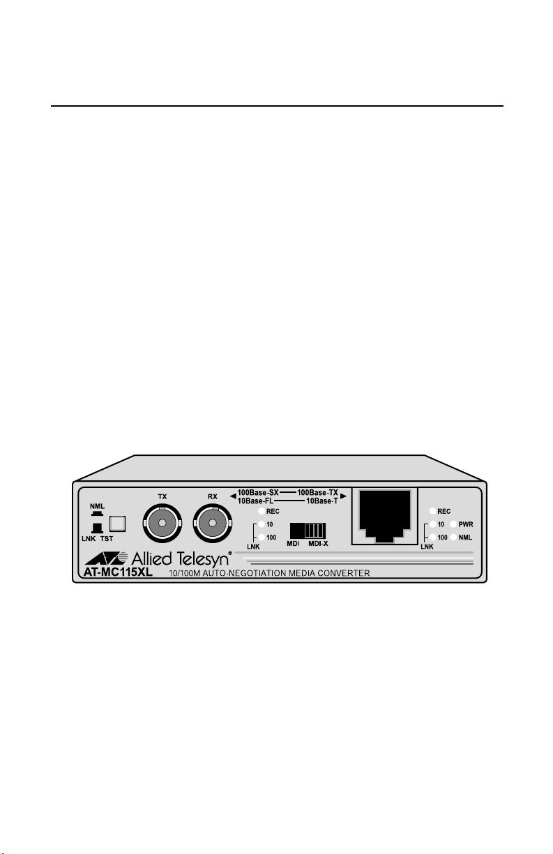
Figure 1 illustrates an AT-MC115XL media converter.
Figure 1 AT-MC115XL Front Panel (ST Connector)
1
Page 12
Overview
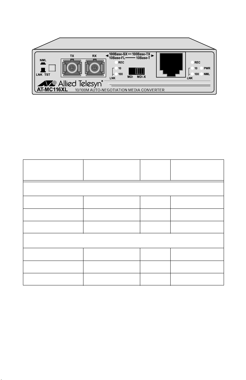
Figure 2 illustrates an AT-MC116XL media converter.
Figure 2 AT-MC116XL Front Panel (SC Connector)
Table 1 lists the maximum operating distances for the AT-MC115XL and
AT-MC116XL media converters. The maximum distance of the fiber optic port
depends on the operating speed.
Table 1 Maximum Operating Distance
Speed Port Type of
Connector
Maximum
Operating Distance
AT-MC115XL
10 Mbps or 100 Mbps 10Base-T/100Base-TX RJ-45 100 m (328 ft)
10 Mbps 10Base-FL ST 2 km (1.2 mi)
100 Mbps 100Base-SX ST 300 m (984 ft)
AT-MC116XL
10 Mbps or 100 Mbps 10Base-T/100Base-TX RJ-45 100 m (328 ft)
10 Mbps 10Base-FL SC 2 km (1.2 mi)
100 Mbps 100Base-SX SC 300 m (984 ft)
1. Maximum operating distance may be less depending on the duplex mode of the end-node and the type of fiber
optic cabling used with the port.
1
2
Page 13

AT-MC115XL and AT-MC116XL Installation Guide
Key Features
The media converters have the following key features:
❑ LEDs for unit and port status
❑ Auto-negotiation for both speed and duplex mode on both ports
❑ MissingLink notifies end-nodes of link failures
❑ MDI/MDI-X switch that eliminates the need for a crossover cable
❑ NML/LNK TST button that performs a link test on the media
converter
❑ External AC/DC power adapters (North America, Continental, or
Europe)
❑ Standard size for use on a desktop or in an AT-MCR12 rackmount
chassis
Status LEDs
Table 2 lists the LEDs for the media converters.
Table 2 AT-MC115XL and AT-MC116XL LEDs
LED Color Description
PWR Green Power is applie d to the media conve rter.
NML Green
OFF
REC Green
OFF
10 Green A link has been establish ed at 10 Mbps.
100 Green A link has been established at 100 Mbps.
The media converter is operating in normal mode.
The media converter is operating in link test mode.
The port is either receiving or transmitting data.
The port is not receiving or transmitt ing data.
3
Page 14

Overview
Twisted Pair Port
The AT-MC115XL and AT-MC116XL media converters have one 10Base-T/
100Base-TX twisted pair port. The twisted pair port features a RJ-45
connector. The m aximum operating distance for the twisted pair port is 100
meters (328 feet) when operating at either 10 Mbps or 100 Mbps.
Fiber Optic Port
The AT-MC115XL and AT-MC116XL media converters have one 10Base-FL/
100Base-SX port. The fiber optic port features either an SC or ST connector,
depending on the model. The maximum operating distance for the fiber optic
port for both the AT-MC115XL and AT-MC116XL is 2 kilometers (1.2 miles)
when operating at 10 Mbps and 300 meters (984 feet) when operating at 100
Mbps.
Auto-negotiation
Port Speed
The twisted pair port is compliant with the 10Base-T and 100Base-TX
standards and is capable of either 10 Mbps or 100 Mbps operation. Since the
port is IEEE 802.3u auto-negotiation compliant, the media co nverter sets the
port speed automatically. With auto-negotiation, the speed of the port is set
automatically by the media converter after it determines the speed of the endnode connected to the port. Auto-negotiation is designed to ensure that the
port on the me dia conve rter and the en d- node a re o perat ing at th e sam e s peed
and that they are communicating at the highest possible common speed of the
devices.
The fiber optic port is compliant with the 10Base-FL and 100Base-SX
standards and can auto-negotiate the operating speed. The end-node
connected to the fiber optic port on the media converter must also be able to
operate at 10 Mbps, 100 Mbps, or auto- negotiate the operating speed.
Note
The end-nodes connected to the ports on the media converter must be
able to operate at the same speed.
4
Page 15
AT-MC115XL and AT-MC116XL Installation Guide
Duplex Mode
Duplex mode refers to the way an end-node sends and receives data on the
network. An end-node can operate in either half- or full-duplex mode,
depending on its capabilities. An end-node that is operating in half-duplex
mode can either send data or receive data, but it cannot do both at the same
time. An end-node that is operating in full-duplex mode can send and receive
data simultan eously. The be st network perfo rmance is achieved when an endnode can operate at full-duplex, since the end-node is able to send and receive
data simultaneously.
The twisted pair port and fiber optic port on the media converter can operate
in half-duplex, full-duplex, or auto-negotiate the duplex mode. The med ia
converter sets the duplex mode automatically through auto-negotiation. With
auto-negotiation, if the end-node is capable of full-duplex, the port is set
automatically to full-duplex mode. If the end-node is capable of half-duplex,
the port is set automatically to half-duplex mode.
The AT-MC115XL and AT-MC116XL media converters can operate in fullduplex, half-duplex, or auto-negotiate the duplex mode. However, the endnodes connected to these media converters must operate in the same duplex
mode to avoid a duplex mode mismatch, which can result in poor network
performance.
Figure 3 shows an example of a duplex mode mismatch. A repeater (Unit 1),
capable of operating in half-dupl ex mode on ly, is co nnecte d to the 10 0Base-S X
port on the media converter, while a switch (Unit 2), capable of either half- or
full-duplex mode, is connected to the 10Base-T/100Base-TX port on the media
converter.
Unit 1
10/100Base-TX Repeater
Media Converter 10/10 0Bas e-TX Switch
Unit 2
Figure 3 Example of a Duplex Mode Mismatch
In attempting to auto-negotiate with Unit 1, the media converter will
determine that the repeater is capable of half-duplex only and will set the port
connected to the unit appropriately. In auto-negotiating with Unit 2, the
media converter will determine th at the switch can manage full-duplex and
will set the port connected to the switch to full-duplex. The result is a duplex
mode mismatch, with one unit operating in half-duplex and the other unit
operating in full-duplex. You could resolve this duplex mode mismatch by
manually configuring Unit 2, if possible, so that the port connected to the
media converter is set to half-duplex.
5
Page 16

Overview
MDI/MDI-X Switch
An RJ-45 port on a 10 Mbps or 100 Mbps Ethernet network device can have
one of two possible wiring configurations: MDI or MDI-X. The RJ-45 port on a
PC, router or bridge is typically wired as MDI, while the twisted pai r port on a
switch or hub is usually MDI-X.
To connect two 10 Mbps or 100 Mbps network devices together that have
dissimilar port wiring configurations, such as MDI to MDI-X, you use a
straight-through cable. To connect two network devices that have an RJ-45
port with the same wiring configuration, such as MDI to MDI, you use a
crossover cable.
The RJ-45 port on the media converters features an MDI/MDI-X switch. You
can use this switch to configure the twisted pair port on the media converter
as either MDI or MDI-X. This feature allows you to use a straight-through
cable regardless of the type of end-node connected to the port.
NML/LNK TST Switch
The NML/LNK TST (Normal MissingLink/Link Test) button allows you to
perform a link test on the ports on the media converter. This button also
allows you to activate the MissingLink feature on the unit. The MissingLink
and Link Test features are describe below.
MissingLink. The Missi ngLink featu re allows th e ports on the me dia converte r
to pass the “Link” status of their connections to each other. When the media
converter detects a problem with one of the ports, such as the los s of
connection to a node, the media converter shuts down the connection to the
other port, thus notifying the node that the connection has been lost.
For example, if the twisted pair cable to the AT-MC115XL were to fail, the
media converter would respond by dropping the link on the fiber optic port. In
this way, the AT-MC115XL notifies the end-node connected to the fiber optic
port that the connection on the twisted pair port has been lost. If the failure
had started with the fiber optic cabling, the media converter would drop the
link to the twisted pair port.
The value to this type of network monitoring and fault notification is that
some hubs and switches can be configured to take a specific action in the event
of the loss of connection on a port. In some cases, the unit can be configured to
seek a redundant path to a disconnected end-node or send out a trap to a
network management station, and so alert the network ad mi nist rator of the
problem.
6
Page 17

AT-MC115XL and AT-MC116XL Installation Guide
Note
The MissingLink feature is disabled when you perform a link test with
the NML/LNK TST button. Consequently, to ensure that the
MissingLink feature is activated on the media converter, always set the
button to the NML (IN) position during normal network operations.
Link Test. A link test is a fast and easy way for you to test the connections
between the ports on the media converter and the end-nodes that are
connected to the ports. If a network problem occurs, you can perform a link
test to determine which port is experiencing a problem, so that you can focus
your troubleshooting efforts on the cable and end-node where the problem
resides.
A link test is performed when the NML/LNK TST button is in the LNK TST
(OUT) position.
Note
Performing a link test does not interfere with a media converter’s ability
to pass network traffic.
External Power Adapter
An external AC/DC power adapter is provided with the media converter for
use on a desktop. The power adapter supplies 1 2 V DC to the media converter.
Allied Telesyn supplies an approved safety compliant AC power adapter for
the 120 V AC and 240 V AC versions with an unregulated output of 12 V DC
at 1 A. The power required for the media converter is 12 V DC, 500 mA.
7
Page 18

Overview
Network Topologies
The AT-MC115XL and AT-MC116XL media converters can be used in two
different topologies: standalone and back-to-back. Both types of topologies are
described below.
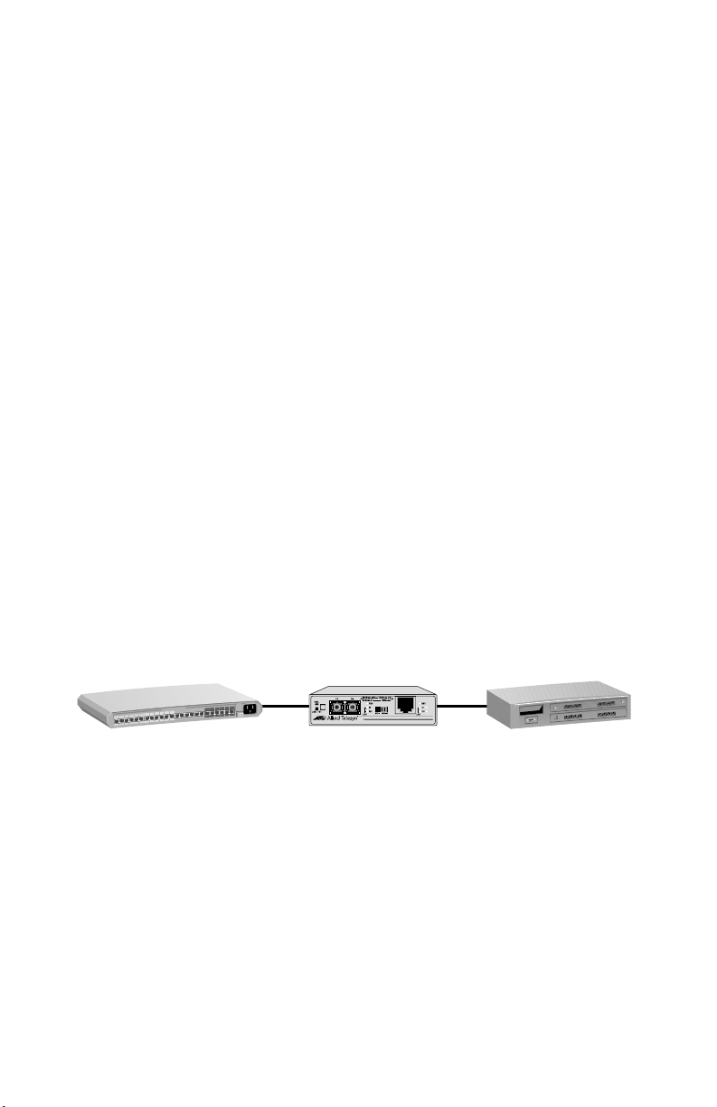
Standalone Topology
A standalone topology uses one media converter between the end-nodes.
Figure 4 illustrates a standalone topology that uses an AT-MC115XL media
converter to connect a wor kstation and a switch.
AT-8224XL Switch
100 m (328 ft) at
10 or 100 Mbps
AT-MC115XL
8
2 km (1.2 mi) at 10 Mbps
or 300 m (984 ft) at 100 Mbps
Fiber Optic
Twisted Pair
Workstation
Figure 4 Stan dalone Topology
Page 19

AT-MC115XL and AT-MC116XL Installation Guide
Back-to-Back Topology
In some network configurations you may want to interconnect two media
converters in what is referred to as a back-to-back topology. In this topology,
the media converters not only extend the distance of your network but als o
convert the fiber optic cable from twisted pair to fiber optic and back again.
Figure 5 illustrates two AT-8224X L swi t ches at different campuses
interconnected by two AT-MC116XL media converters. The 10Base-T/
100Base-TX ports on the media converters are connected to one 10/
100Base-TX port on each switch, while the 10Base-FL/100Base-SX ports on
the media converters are directly connected together.
AT-8224XL Switch
100 m (328 ft) at 10 or 100 Mbps
Fiber Optic
Twisted Pair
AT-MC116XL
2 km (1.2 mi) at 10 Mbps
or 300 m (984 ft) at 100 Mbps
AT-8224XL Switch
Figure 5 Back-to-Back Topology
AT-MC116XL
100 m (328 ft)
at 10 or 100 Mbps
9
Page 20

Page 21

Chapter 2
Installing the Media Converter
Verifying the Package Contents
Make sure the following items are included in your package. If any item is
missing or damaged, contact your Allie d Telesyn sales representative for
assistance.
❑ One AT-MC115XL or AT-MC116XL Ethernet and Fast Ethernet
Media Converter
❑ Four protective feet (for desktop use only)
❑ External power adapter
❑ This installation guide
❑ Warranty card
Planning the Installation
Be sure to observe the following guidelines when planning the installation of
your media converter.
❑ The end-nodes connected to the ports on the media converter must be
able to operate at the same speed and duplex mode.
❑ The twisted pair port cabling must be kept away from sources of
electrical noise, such as radios, transmitters, power lines, broadband
amplifiers electrical motors, and fl uorescent fixtures.
11
Page 22

Installing the Media Converter
❑ Refer to the following tables for the cabling specifications for the
twisted pair port and fiber optic port.
Table 3 1 0Base-T/100Base-TX Twisted Pair Port Cabling Sp ecifications
Operating Mode Twisted Pair Cable Maximum Operating
Distance
10Base-T Category 3 or better 100 m (328 ft)
100Base-TX Category 5 or better 100 m (328 ft)
Table 4 10Base-FL/100Base-SX Fiber Optic Port Cabling Specif ications (Full-duplex)
Model Fiber Optic Cable Maximum
Operating
Maximum Allowa ble Loss
Budget
Distance
1
AT-MC115XL
and
AT-MC116XL
1. Operating at 100 Mbps.
2. Operating at 10 Mbps.
50/125 or 62.5/125
micron multimode
300 m (984 ft)
or
2 km (1.2 mi)
1.5 dB at 850 nm
2
Note
For additional fiber optic port specifications, refer to “Fib er Optic Port
Specifications” on page 20.
Selecting a Site
Be sure to observe the following requirements when choosing a site for your
switch.
❑ Select a site that is dust-free and moisture-free.
❑ Be sure that the site will allow you to easily access the fiber optic and
twisted pair cables and the power cord.
❑ Use a dedicated power circuit or a power conditioner to supply reliable
power to the device.
12
Page 23

AT-MC115XL and AT-MC116XL Installation Guide
Reviewing Safety Guidelines
Please review the following safety guidelines before installing the media
converter.
Warning
This is a “Class 1 LED product”. ! 7
Warning
Electrical Shock Hazard: To prevent electrical shock, do not remove
the cover. There are n o user-serviceable parts inside. The unit contains
hazardous voltages and should only be opened by a trained and
qualified technician. ! 8
Warning
Lightning Danger: Do not work on equipment or cables during periods
of lightning activity. ! 9
Caution
Power to the hub must be sourced only from the adapter. ! 10
Caution
Pluggable Equipment: The socket outlet should be installed near the
equipment and should be easily accessible. ! 11
Caution
Air vents: The air vents mus t not b e blo cked o n the unit and m ust hav e
free access to the room ambient air for cooling. ! 12
Caution
Operating Temperature
This product is de signed for a maximum ambient temperature of 40
degrees C. ! 13
Caution
All Countries: Install product in accordance with local and National
Electrical Codes. ! 14
13
Page 24

Installing the Media Converter
Installing the Media Converter
To install an AT-MC115XL or AT-MC116XL media converter, perform the
following proced ur e :
1. Remove all equipme nt fr om the packag e and s tore the pa ckagin g mate rial
in a safe place.
Note
Do not remove the dust cover from the fiber optic port until you are
ready to connect the fiber optic cable. Dust contamination can adversely
impact the operating performance of the port on the media converter.
2. If you are installing the media converter on a desktop, attach the four
rubber feet to the bottom of the unit. Refer to Figure 6. Do not attach
the rubber feet if you are installing the unit in an AT-MCR12
chassis.
Figure 6 Attaching the Protective Feet
3. If you are installing the media converter in an AT-MCR12 chassis, refer to
the chassis’s installa t io n gui de for inst ru ct io ns on ho w to inst a ll t he uni t,
then proceed to Step 6.
4. Place the media converter on a flat, secure surface (such as a desk or
table) leaving ample space around the unit for ventilation.
14
Page 25

AT-MC115XL and AT-MC116XL Installation Guide
5. Plug the AC/DC power adapter into an appropriate AC power outlet and
insert the power plug into the DC receptacle located on the back of the
unit. Refer to Figure 7. This step does not apply if you installed the
unit in an AT-MCR12 chassis.
Power Plug
AC/DC Power Adapter
DC Receptacle
Back of Media Converter
Figure 7 DC Co nnector
6. Verify that the PWR LED is green. If the LED is OFF, refer to
“Troubleshooting” on page 17 for ins tructions.
7. Remove the dust cover from the fiber optic connector and connect the
cable to the fiber optic port. Verify that the media converter’s transmitter
port (TX) is connected to the end-node’s receiver port (RX) and that the
media converter’s receiver port (RX) is connected to the end-node’s
transmitter port (TX).
8. Connect the twisted pair cable to the twisted pair port.
9. Set the MDI/MDI-X switch as follows:
— If you are connecting a workstation to the 1 0Bas e-T/100Ba se -TX port ,
set the MDI/MDI-X switch to the MDI-X position. (MDI-X is the
default.)
— If you are connecting a hub or switch to the 10Bas e-T/100Base-TX port,
set the MDI/MDI-X switch to the MDI position.
10. Power on the end-nodes.
11. Depending on your configuration, check that the 10 or 100 LED for both
ports on the media converter are green. If the LEDs are OFF, refer to
“Troubleshooting” on page 17.
The media converter is now ready for use.
15
Page 26

Installing the Media Converter
Warranty Registration
When you finish installing the product, you should register your product by
completing the enclosed warranty card and sending it in.
16
Page 27

Chapter 3
Troubleshooting
Follow the guidelines below to test and troubles hoot the installation in the
event of a problem occurs.
If the PWR LED is OFF, do the following;
❑ If the unit is installed on a desktop, check to be sure that the power
adapter is securely connected to a power outlet and that the power
adapter cable is securely connected to the back of the media converter.
❑ If the unit is installed i n an AT-MCR12 chassis, che ck that the un it is
fully seated in the slot.
❑ Verify that the power outlet has power by connecting another device
to it.
❑ Try using another power adapter of the same type that came with your
media converter.
If the LNK 10 or 100 LED for the twisted pair port is OFF, do the following:
❑ Check that the end-node connected to the port is powered ON and is
operating properly.
❑ Check that the twisted pair cable is securely connected to the twisted
pair port on the media converter and on the remote end-node.
❑ Make sure that the twist ed pair cable does not excee d 100 meters (328
feet) and that you are using Category 3 or better cable for 10 Mbps
operation or Catergory 5 or better for 100 Mbps operation.
❑ Verify that both end-nodes connected to the media converter are
operating at the same speed. Both must be op erating at either 10
Mbps or 100 Mbps.
17
Page 28

Troubleshooting
If the LNK 10 or 100 LED for the fiber optic port is OFF, do the following:
❑ Verify that the end-node connected to the port is ON and is operating
properly.
❑ Check that the fiber optic cable is securely connected to the fiber optic
port on the media converter and on the end-node.
❑ Verify that the end-nodes connected to the media converter are
operating at the same speed. Both must be op erating at either 10
Mbps or 100 Mbps.
❑ Make sure that the cable connected to the media converter’s receiver
port (RX) is connected to the end-node’s transmitter port (TX) and that
the media converter’s transmitter port (TX) is connected to the endnode’s receiver port (RX).
❑ Test the attenuation on the fiber optic cable to ensure that it does not
exceed acce ptable va lues. Refe r to “Fi ber Optic P ort Spec ificatio ns” on
page 20 for more information.
❑ Verify that you are using the appropriate type of fiber optic cable and
that you have not exc eeded the maximum operating distance. For
maximum operating distances, refer to Table 1 on page 2 . For cable
types, Refer to “Fiber Optic Port Specifications” on page 20.
❑ Check that the operating specifications (e.g., wavelength and
maximum operating distance) of the fiber optic port on the end-node
are compatible w ith th e operati ng spec ificatio ns of the fiber op tic port
on the media converter. Refer to “F iber Optic Port Specifications” on
page 20 for information.
If there is a communication problem between the end-nodes connected to the
media converter, do the following:
❑ Verify that both end-nodes are operating with the same duplex mode.
If you are still experiencing problems after testing and troubleshooting the
installation, refer to “Contacting Allied Telesyn Technical Support” on page
viii or visit our web site at www.alliedtelesyn.com for support information.
18
Page 29

Appendix A
Technical Specifications
Physical
Dimensions: W x D x H
10.5 cm x 9.5 cm x 2.5 cm
(4.125 in x 3.75 in x 1.0 in)
Weight: 294 g (10.4 oz)
Environmental
Maximum Operating: 0° C to 40° C (32° F to 104° F)
Maximum Storage: -20
Relative Humidity Operating
and Storage: 5% to 95% (non-condensing)
Operating and Storage Altitude: Up to 3,048 meters (10,000 feet)
o
C to 80o C (-4° F to 176° F)
Electrical Rating
Input Supply Voltage: 12 V DC
Maximum Current: 500 mA
Power Consumption: 6W
Agency Compliance
EMI/RFI: EN55022 Class B, FCC Class B
Electrical Safety: TUV-EN60950, UL60950 (UL/cUL)
Immunity: EN55024
19
Page 30

Technical Specifications
Fiber Optic Port Specifications
Table 5 through Table 8 lists the specifications for the 10Base-FL/100Base-SX
fiber optic port.
Table 5 Fiber Optic Transmi tter
Model Fiber
Type
Fiber
1
Optic
Optical
Wavelength
Diameter
AT-MC115XL
and
MMF 50/125
microns
850 nm -13.0 -15.8 -18.8
AT-MC116XL
MMF 62.5/125
850 nm -10.0 -12.0 -15.0
microns
1. MMF = Multimode Fiber.
2. The launch power is measured at one meter from the transmitter.
Table 6 Fiber Optic Receiver
Model Fiber
Type
Fiber
1
Optic
Optical
Wavelength
Diameter
AT-MC115XL
and
AT-MC116XL
MMF 50/125
microns or
62.5/125
850 nm -41.4 -43.0 -7.6
microns
1. MMF = Multimode Fiber.
Launch Power (dBm)
2
Maximum Average Minimum
Receiver Sensitivity (dBm)
Minimum Average Maximum
20
Page 31

AT-MC115XL and AT-MC116XL Installation Guide
Table 7 Fiber Optic Dat alink
Model Fiber
Type
AT-MC115XL
MMF 50/125
and
AT-MC116XL
MMF 62.5/125
1. MMF = Multimode Fiber.
2. Half-duplex only.
3. Operating at 100 Mbps.
4. Operating at 10 Mbps.
Table 8 Fiber Optic Loss Specification (Benchmarks)
Fiber
Type
1
Fiber Optic
Diameter
1
Fiber
Optic
Diameter
microns
microns
Optical
Wavelength
Optical
Wavelength
Minimum
Power/
Link
Average
Signal
Loss
Maximum
Distance
Spec
Budget
850 nm 26.40 dB 31.50 dB 300 m
(984 ft)
or
2 km
(1.2 mi)
850 nm 36.40 dB 40.0 dB 300 m
(984 ft)
or
2 km
(1.2 mi)
Typical Loss
Factor
Worst Case
Loss
Bandwidth
(Mhz-km)
Factor
2
3
4
3
4
MMF 50/125 microns 850 nm 3.00 dB/km 3.50 dB/km 400
MMF 62.5/125
850 nm 3.00 dB/km 3.75 dB/km 200
microns
1. MMF = Multimode Fiber.
21
Page 32

Technical Specifications
Pinout Assignments
Figure 8 shows the pin assignmen ts of the RJ-45 connector.
Pin 1 Pin 8
Figure 8 RJ-45 Pin Assignments
Table 9 lists the 10Base-T/100Base-TX connector pins and their signals when
the port is operating in either MDI or MDI-X configuration.
Table 9 RJ-45 Pin Signals
MDI-X (Default) Signal MDI Signal
1RX+1 TX+
2RX-2 TX3 TX+ 3 RX+
4- 4 5- 5 6 TX- 6 RX7- 7 8- 8 -
22
Page 33

Appendix B
Translated Safety and Emission Information
Important: This appendix contains multiple-language translations for the
safety statements in this guide.
Wichtig: Dieser Anhang enthält Übersetzungen der in diesem Handbuch
enthaltenen Sicherheitshinweise in mehreren Sprachen.
Vigtigt: Dette tillæg indeholder oversættelser i flere sprog af
sikkerhedsadvarslerne i denne håndbog.
Belangrijk: Deze appendix bevat vertalingen in meerdere talen van de
veiligheidsopmerkingen in deze gids.
Important: Cette annexe contient la traduction en plusieurs langues des
instructions de sécurité figurant dans ce guide.
Tärkeää: Tämä liite sisältää tässä oppaassa esiintyvät turvaohjeet usealla
kielellä.
Importante: questa appendice contiene traduzioni in più lingue degli avvisi
di sicurezza di questa guida.
Viktig: Dette tillegget inneholder oversettelser til flere språk av
sikkerhetsinformasjonen i denne veiledningen.
Importante: Este anexo contém traduções em vários idiomas das
advertências de segurança neste guia.
Importante: Este apéndice c ontie ne trad ucci ones e n múlt iples idi omas de los
mensajes de seguridad incluidos en esta guía.
Obs! Denna bilaga innehåller flerspråkiga översättningar av
säkerhetsmeddelandena i denna handledning.
23
Page 34

Translated Safety an d Emission Information
Standards: This product meets the following standards.
U.S. Federal Communications Commission
Declaration Of Conformity
Manufacture Name: Allied Telesyn, Inc.
Manufacture Address: 960 Stewart Drive, Suite B
Manufacture Telephone: 408-730-0950
Declares that the product: Ethernet and Fast Ethernet
Model Numbers: AT-MC115XL, AT-MC116XL
This product complies with FCC Part 15B, Class B Limits:
This device complies with part 15 of the FCC Rules. Operation is subject
to the following two conditions: (1) This device must not cause harmful
interference, and (2) this device must a ccept any interference received,
including interferenc e that may cau s e undes ir ed ope ratio n.
Radiated Energy
Note: This equipment has been tested and found to comply with the
limits for a Class B digital device pursuant to Part 15 of FCC Rules.
These limits are designed to provide reasonable protection against
harmful interference in a residential installation. This equipment
generates, uses and can radiate radio frequency energy and, if not
installed and used in accordance with instructions, may cause harmful
interference to rad i o or television recep t ion, which can be determined by
turning the equipment off and on. The user is encouraged to try to correct
the interference by one or more of the follow ing meas u re s:
- Reorient or relocate the receiving antenna.
- Increase the separation between the equipment and the receiver.
- Connect the equipment into an outlet on a circuit different from that to
which the receiver is connected.
- Consult the dealer or an experienced radio/TV technician for help.
Changes and modifications not expressly approved by the manufacturer
or registrant of this equipment can void your auth or ity to operate this
equipment under Federal Communications Commission rules.
Sunnyvale, CA 94085 USA
Media Converte rs
Industry Canada
This Class B digital apparatus meets all requirements of the Canadian
Interference-Causing Eq uipment Regula t ions.
Cet appareil numérique de la classe B respecte toutes les exigences du
Règlement sur le matériel brouilleur du Canada.
24
Page 35
AT-MC115XL and AT-MC116XL Installation Guide
! 1RFI Emission EN55022 Class B
! 2Warning: In a domestic environment this product may cause radio
interference in which case the user may be required to take adequate
measures.
! 3Immunity EN55024
! 4Warning: This product requires shielded cables to comply with emission
and immunity standard s. If it is used with unshi elded cables, the user ma y
be required to take measures to correct the interference problem at their own
expense.
! 5 Electrical Safety TUV-EN60950, UL60950 (UL/cUL)
! 6Laser/LED EN60825
! 7 This is a “Class 1 LED Product”
! 8Warning
Electrical Shock Hazard: To prevent electrical shock, do not remove the
cover. There are no user-servicable parts inside. The unit contains
hazardous voltages and should only be opened by a trained and qualified
technician.
Safety
! 9 Lightning Danger
Danger: Do not work on equipment or cables during periods of lightning
activity.
! 10 Power to the hub must be sourced only from the adapter.
USA/Canada
Use a UL Listed/CSA Certified AC adapter of DC 12V, minimum 500 mA
rope - EU
Eu
Use TÜV licensed AC adapter of DC 12V, minimum 500 mA.
UK
Use a UK Safety Approved AC adapter of DC 12 V, minimum 500 mA.
! 11 Caution
Pluggable Equipment: The socket outlet should be installed near the
equipment ans should be easily accessible
! 12 Caution
Air vents: The air vents must not be blocked on the unit and must have free
access to the room ambient air for cooling.
! 13 Operating Temperature: This product is designed for a maximum
ambient temperature of 40 degrees C.
! 14 All Countries: Install product in accordance with local and National
Electrical Codes.
25
Page 36

Translated Safety an d Emission Information
Normen: Dieses Produkt erfüllt die An for d er ung e n der nac hf olg en den
Normen.
! 1 Hochfrequenzstörung EN55022 K lasse B
! 2 Warnung: Bei Verwendung z u Hause kann diese s Produkt Funk störungen
hervorrufen. In diesem Fall müßte der Anwende r an gemessene
Gegenmaßnahmen ergreifen.
! 3Störsicherheit EN55024
! 4 Achtung: Für dieses Produkt sind abgeschirmte Kabel erforderlich, damit
den Richtlinien f ür Emission u nd Interf erenzsch utz entsproch en wird. F alls
das Produkt mit nicht abgeschirmten Kabeln verwendet wird, können
weitergehende Maßnahmen für die Korrektur von Interferenzproblemen auf
Kosten des Benutzers notwendig werden.
! 5 Elektrische Sicherheit TUV-EN60950, UL60950 (UL/cUL)
! 6Laser/LED EN60825
! 7 Das ist ein “LED Produkt der Klasse 1”
! 8 Achtung: Gefährli che Spannung
Das Gehäuse nicht öffnen. Das Gerät enthält keine vom Benutzer wartbaren
Teile. Das Gerät st eht unter H ochspannung u nd darf nur vo n qualifizi ertem
technischem Pers onal geöffn et werden. Vor An schluß der LAN-K abel, Gerät
vom Netz trennen.
Sicherheit
! 9 Gefahr Durch Bli tz sc hl ag
Gefahr: Keine Arbeiten am Gerät oder an den Kabeln während eines
Gewitters ausführen.
! 10 Der Buchse darf nur aus dem Adapter Strom zugefüh rt werden.
Europe - EU
Gebrauchen Sie einen von TÜV zugelassenen Wechselstromadapte r für
Gleichstrom 12 V, 500 mA.
! 11 Steckbares Gerät: Die Anschlußbuchse sollte in der Nähe der Einrichtung
angebracht werden und leicht zugänglich sein.”
! 12 Vorsicht
Die Entlüftungsöffnungen dürfen nicht versperrt sein und müssen zum
Kühlen freien Zugang zu r Rau m l uft haben.
! 13 Betriebstempe ratur: Dieses Produkt wurde für den Betrieb in einer
Umgebungstemperatur von nicht mehr als 40° C entworfen.
! 14 Alle Länder: Installation muß örtlichen und nationalen elektrischen
Vorschriften entsprechen.
26
Page 37

AT-MC115XL and AT-MC116XL Installation Guide
Standarder: Dette produkt tilfredsstiller de følgen de standarde r.
! 1 Radiofrekvens
forstyrrelsesemission EN55022 Klasse B
! 2 Advarsel: I et hjemligt miljø kunne dette produkt forårsage radio
forstyrrelse. Bliver det tilfældet, påkræves brugeren muligvis at tage
tilstrækkelige foranstaltninger.
! 3Immunitet EN55024
! 4 Advarsel: Dette produkt skal bruges med afskærmede kabler for at
overholde bestemmelserne vedrørende udstråling og støjimmunitet. Hvis
det bruges med uafskærmede kabler, kan det blive påkrævet af brugeren at
korrigere interferenspr oblemer for egen regning.
! 5 Elektrisk sikkerhed TUV-EN60950, UL60950 (UL/cUL)
! 6Laser/LED EN60825
! 7 Dette er et “Produkt Under Klasse 1 LED”
! 8 Elektriske Forholdsregler
Advarsel: Risiko For Elektrisk Stød
For at forebygge elektrisk stød, undlad at åbne apparatet. Der er ingen indre
dele, der kan repareres af brugeren. Denne enhed indeholder livsfarlige
strømspændinger og bør kun åbnes af en uddannet og kvalificeret tekniker.
For at undgå risiko for elektrisk stød, afbrydes den elektriske strøm til
produktet, før LAN-kablerne monteres eller afmonteres.
Sikkerhed
! 9Fare Under Uvejr
Fare: Undlad at arbejde på udstyr eller kabler i perioder med lynaktivitet.
! 10 Strømforsyningen til apparatet må udelukkende tages fra
tilpasningstransformatoren.
Europe - EU
Brug kun TÜV godkendt vekselstrømstransformator på 12 V jævnstrøm,
500 mA.
! 11 Udstyr Til Stikkontakt, stikkontakten bør installeres nær ved udstyret og
skal være lettilgængelig.rummet for afkøling.
! 12 Advarsel: Ventilationsåbninger må ikke blokeres og skal have fri adgang til
den omgivende luft i rummet for afkøling.
! 13 Betjeningstemperatur: Dette apparat er konstrueret til en omgivende
temperatur på maksimum 40 grader C.
! 14 Alle Lande: Installation af produktet skal ske i overensstemmelse med
lokal og national lovgivning for elektriske installationer.
27
Page 38

Translated Safety an d Emission Information
Eisen: Dit product voldoet aan de volgende eisen.
! 1 RFI Emissie EN55022 Klasse B
! 2 Waarschuwing: Binnenshuis kan dit product radi ostori ng veroorz aken, in
welk geval de gebruiker verplicht kan worden om gepaste maatregelen te
nemen.
! 3Immuniteit EN55024
! 4 Waarschuwing: Om te voldoen aan de emissie- en immuniteitsnormen
dient dit apparaat te zijn voorzien van afgeschermde kabels. Als het met
niet-afgeschermde kabels wordt geb ruikt, kan het zijn dat de ge b rui ker
maatregelen moet treffen om interferentieproblemen voor eigen rekening op
te lossen.
! 5 Electrische Veiligheid TUV-EN60950, UL60950 (UL/cUL)
! 6Laser/LED EN60825
! 7 Dit is een “Klasse 1 LED-produkt
! 8 Waarschuwingen Met Betrekking Tot Elektriciteit
Waarschuwing: Gevaar voor elektrische schokken verwijder het deksel
niet, teneinde elektrische schokken t e vo orkomen. Binnenin bevi nden zich
geen onderdelen die door de gebruiker onderhouden kunnen worden. Dit
toestel staat onder gevaarlijke spanning en mag alleen worden geopend door
een daartoe opgeleide en bevoegde technicus. Om het gevaar op elektrische
schokken te vermijden, moet u het toestel va n de s troombron ontkoppelen
alvorens de LAN-kabels te koppelen of ontkoppelen.
Veiligheid
! 9 Gevaar Voor Blikseminslag
Gevaar: Niet aan toestellen of kabels werken bij bliksem.
! 10 Stroom mag alleen via de adapter naar het apparaat toegevoerd worden.
Europe - EU
Gebruik een door TÜV gekeurde wisselstroomadapter van 12 Volt
gelijkstroom, 500 milliampères.
! 11 Aan te sluiten apparatuur, de contactdoos wordt in de nabijheid van de
apparatuur geïnstalleerd en is gemakkelijk te bereiken.
! 12 Opgelet: De ventilatiegate n mogen niet worden gesperd en moeten de
omgevingslucht ongehinder d toelaten voor afkoelin g .
! 13 Bedrijfstemperatuur: De omgevingstemperatuur voor dit produkt mag
niet meer bedragen dan 40 graden Celsius.
! 14 Alle Landen: het toestel installeren overeenkomstig de lokale en nationale
elektrische voorschriften.
28
Page 39

AT-MC115XL and AT-MC116XL Installation Guide
Normes: ce produit est conforme aux normes de suivantes:
! 1 Emission d'interférences
radioélectriques EN55022 Classe B
! 2Mise En Garde: da ns un environneme nt do mestique, ce p roduit peut
provoquer des interférences radioélectriques. Auquel cas, l'utilisateur devra
prendre les mesures adéquates.
! 3Immunité EN55024
! 4Avertissement: Il faut utiliser des câbles blindés pour ce produit afin de
respecter les normes d’émission et d’immunité. Si l’utilisateur choisit
d’utiliser des câbles non blindés, il sera peut-être contraint de prendre les
mesures nécessaires pour corriger les problèmes d’interférences, ainsi que
d’assumer l e coût correspond a n t .
! 5 Sécurité électrique TUV-EN60950, UL60950 (UL/cUL)
! 6Laser/LED EN60825
! 7 Ce matériel est un “Produit À Diode Électroluminescente De Classe 1”
! 8 Information Sur Les Risques Électriques
Avertissement: Danger d’électrocution
pour éviter toute électrocution, ne pas ôter le revêtement protecteur du
matériel. Ce matériel ne contient aucun élément réparable par l’utilisateur.
Il comprend des tensions dangereuses et ne doit être ouvert que par un
technicien dûment qualifié. Pour éviter tout risque d’électrocution,
débrancher le matériel avant de connecter ou de déconnecter les câbles LAN.
Sécurité
! 9Danger De Foudre
Danger: Ne pas manier le matériel ou les câbles lors d'activité orageuse.
! 10 L’alimentation du concentrateu r doit êtr e uniqu ement fournie par
l’adaptateur.
Europe - EU
Utiliser un adaptateur secteur conforme TÜV de 12 V, 500 mA en courant
continu.
! 11 Equipement pour branchement electrique, la prise de sortie doit être placée
près de l’équipement et facilement accessible”.
! 12 Attention: Ne pas bloquer les fentes d’aération, ceci empêcherait l’air
ambiant de circuler li brement pour le refroidisse ment .
! 13 Température De F onctionnement: Ce matériel est capable de tolérer une
température ambiante maximum de 40 degrés Celsius.
! 14 Pour Tous Pays: Installer le matériel conformément aux normes
électriques nationales et locales.
29
Page 40
Translated Safety an d Emission Information
Standardit: Tämä tuote on seuraavien standardien mukain en.
! 1 Radioaaltojen häirintä EN55022 Luokka B
! 2Varoitus: Kotiolosuhteissa tämä laite voi aiheuttaa radioaaltojen häiröitä,
missä tapauksessa laitteen käyttäjän on mahdollisesti ryhdyttävä
tarpeellisiin toimenpiteisiin.
! 3 Kestävyys EN55024
! 4Varoitus: Tämä tuote vaatii suojattuja kaapeleita toimiakseen emissio- ja
häiriönsietostandardien mukaisesti. Jos tuotetta käytetään ilman
suojattuja kaapeleita, käyttäjä voi joutua korjaamaan häirinnän
aiheuttaman ongelman omalla kustannuksellaan.
! 5 Sähköturvallisuus TUV-EN60950, UL60950 (UL/cUL)
! 6Laser/LED EN60825
! 7 Tämä on “Ensimmäisen Luokan Valodiodituote”
! 8 Sähköön Liittyviä Huomautuksia
Varoitus: Sähköiskuvaara
Estääksesi sähköiskun älä poista kantta. Sisällä ei ole käyttäjän
huollettavissa olevia osia. Tämä laite sisältää vaarallisia jännitteitä ja sen
voi avata vain koulutettu ja pätevä teknikko. Välttääksesi sähköiskun
mahdollisuuden katkaise sähkövirta tuotteeseen ennen kuin liität tai
irrotat paikallisverkon (LAN) kaapelit.
Turvallisuus
! 9 Salamaniskuvaara
Engenvaara: Älä työskentele laitteiden tai kaapeleiden kanssa
salamoinni n a i kana.
! 10 Tähtipisteeseen (hub) syötettävän virran pitää tulla ainoastaan
sovittimesta.
Europe - EU
Käytä TÜV-lisenssillä valmistettua verkkosovitinta, jonka tasajännitteen
nimellisarvot ovat DC 12 V, 500 mA (milliampeeria).
! 11 Pistorasiaan kytkettävä laite; pistorasia on asennettava laitteen lähelle ja
siihen on oltava esteetön pääsy.”
! 12 Huomautus: Ilmavaihtoreikiä ei pidä tukkia ja niillä täytyy olla vapaa
yhteys ympäröivään huoneilmaan, jotta ilmanvaihto tapahtuisi.
! 13 Käyttölämpötila: Tämä tuote on suunniteltu ympäröivän ilman
maksimilämpötilalle 40° C.
! 14 Kaikki Maat: Asenna tuote paikallisten ja kansallisten
sähköturvallisuusmääräysten mukaisesti.
30
Page 41

AT-MC115XL and AT-MC116XL Installation Guide
Standard: Questo prodotto è conforme ai seguenti standard.
! 1 Emissione RFI (interferenza
di radiofrequenza) EN55022 Classe B
! 2 Avvertenza: in ambiente domestico questo prodotto potrebbe causare radio
interferenza. In questo caso potrebbe richiedersi all'utente di prendere gli
adeguati provvedi menti.
! 3Immunità EN55024
! 4 Avvertenza: questo prodotto, se utilizzato con cavi schermati, è conforme
alle norme sulle emissioni e sull’immunità. In caso di uso senza cavi
schermati, l’utente può dover adottare a proprie spese misure correttive
contro le interferenze.
! 5 Sicurezza Elettrica TUV-EN60950, UL60950 (UL/cUL )
! 6Laser/LED EN60825
! 7 Questo è un “Prodotto Con LED Di Classe 1”
! 8 Avvertenze Elettriche
Attenzione: Pericolo di scosse elettriche per evitare scosse elettriche non
asportare il coperchio. Le componenti interne non sono riparabili dall’utente.
Questa unità ha tensioni pericolose e va aperta solamente da un tecnico
specializzato e qualificato. Per evitare ogni possibilità di scosse elettriche,
interrompere l’alimentazione del dispositivo prima di collegare o staccare i
cavi LAN.
Norme Di Sicurezza
! 9 Pericolo Di Fulmini
Pericolo: Non lavorare sul dispositivo o sui cavi durante prec ipitazioni
temporalesche.
! 10 Questo dispositivo deve essere alimentato solo mediante l’adattatore.
Europe - EU
Utilizzare l’adattatore per c.a. da 12 V c.c. e 500 mA conforme alla normativa
TÜV.
! 11 Apparecchiatura collegabile, la presa va installata vicino all’apparecchio per
risultare facilmente accessibile”.
! 12 Attenzione: le pres e d ’ari a no n vann o os tru it e e devo no co nse ntir e il li ber o
ricircolo dell’aria ambiente per il raffreddamento.
! 13 Temperatura Di Funzionamento: Questo prod otto è conc epito pe r un a
temperatura ambientale massima di 40 gradi centigradi.
! 14 Tutti I Paesi: installare il prodotto in conformità delle vigenti normative
elettriche nazionali.
31
Page 42

Translated Safety an d Emission Information
Sikkerhetsnormer: Dette produktet tilfredsstiller følgende
sikkerhetsnormer.
! 1RFI stråling EN55022 Klasse B
! 2 Advarsel: Hvis dette produktet benyttes til privat bruk, kan produktet
forårsake radioforstyrrelse. Hvis dette skjer, må brukeren ta de nødvendige
forholdsregler.
! 3Immunitet EN55024
! 4 Advarsel: Dette produktet må brukes med vernede kabler for å tilfredsstille
emisjons- og frit akelsesst andarder. Der som produkt et brukes med uvernede
kabler, må brukeren muligens rette forstyrrelsesproblemene for egen
regning.
! 5 Elektrisk Sik kerhet TU V-EN60950 , UL6095 0 (UL/ cUL )
! 6Laser/LED EN60825
! 7 Dette er et “Klasse 1 LED Produkt”
! 8 Elektrisitet
Advarsel: Fare for elektrisk sjokk for å unngå elektrisk sjokk, m å d eks let
ikke tas av. Det finnes ingen deler som brukeren kan reparere på innsiden.
Denne enheten inne holder farlig e spenni nger , og må kun åpne s av en fagl ig
kvalifisert tekniker. For å unngå elektrisk sjokk må den elektriske
strømmen til produktet være avslått før LAN-kablene til- eller frakobles.
Sikkerhet
! 9 Fare For Lynnedslag
Fare: Arbeid ikke på utstyr eller kabler i tordenvær.
! 10 All strømtilførsel må komme fra adapteren.
Europe - EU
Benytt TÜV-godkjent AC-adapter på 12V DC, 500mA (millismpere)
! 11 Utstyr for stikkontakt. Stikkontakten skal monteres i nærheten av utstyret
og skal være lett tilgjengelig.”
! 12 Forsiktig: Lufteventilene må ikke blokkeres, og må ha fri tilgang til luft
med romtemperatur for avkjøling.
! 13 Driftstemperatur: Dette produktet er konstruert for bruk i maksimum
romtemperatur på 40 grader celsius.
! 14 Alle Land: Produktet må installeres i samsvar med de lok ale og nasjonale
elektriske koder.
32
Page 43

AT-MC115XL and AT-MC116XL Installation Guide
Padrões: Este produto atende aos seguintes padrões.
! 1 Emissão De Interferência
De Radiofrequência EN55022 Classe B
! 2Aviso: Num ambiente doméstico este produto pode causar interferência na
radiorrecepção e, neste caso, pod e ser n ece s sá rio que o uten te tome as
medidas adequadas.
! 3Imunidade EN55024
! 4Advertência: Este produto requer a utilização de cabos blindados para
cumprimento dos standards de limites de emissão e imunidade. Se o produto
for utilizado com cabos não blindados, o utilizador poderá necessitar de
tomar medidas para correcção de problemas de interferência, por sua própria
conta.
! 5 Segurança Eléctrica TUV-EN60950, UL60950 (UL/cUL)
! 6Laser/LED EN60825
! 7 Este é um “Produto Classe 1 LED”
! 8 Avisos Sobre Características Elétricas
Atenção: Perigo de choque elétrico para evitar choque elétrico, não retire a
tampa. Não contém peças que possam ser consertadas pelo usuário. Este
aparelho contém voltagens perigo sa s e só deve ser ab erto por u m técn ico
qualificado e treinado. Para evitar a possibilidade de choque elétrico,
desconecte o aparelho da fonte de energ ia elétric a antes de conectar e
desconectar os cabos da LAN.
Segurança
! 9 Perigo De Choque Causado Por Raio
Perigo: Não trabalhe no equipamento ou nos cabos durante períodos
suscetíveis a quedas de raio.
! 10 Use somente o adaptador fornec ido par a alimen ta ção elé tric a do hub.
Europe - EU
Use um adaptador de corrente alternada com saída DC de 12V e 500mA em
conformidad e co m as especificações da TÜ V.
! 11 Equipamento de ligação, a tomada eléctrica deve estar instalada perto do
equipamento e ser de fácil acesso.”
! 12 Cuidado: As aberturas de ventilação não devem ser bloqueadas e devem ter
acesso livre ao ar ambiente para arrefecimento adequado do aparelho.
! 13 Temperatura De Funcionamento: Este produto foi projetado para uma
temperatura ambiente máxima de 40 graus centígrados.
! 14 Todos Os Paíse s: Instale o produto de acordo com as normas nacionais e
locais para instalações elétricas.
33
Page 44

Translated Safety an d Emission Information
Estándares Este produc to cumple c on los siguientes están dar es.
! 1 Emisión RFI EN55022 Clase B
! 2Advertencia: en un entorno doméstico, este producto puede causar
radiointerferencias, en cuyo caso, puede requerirse del usuario que tome las
medidas que sean convenientes al respecto.
! 3 Inmunidad EN55024
! 4Advertencia: Este producto exige cables protectores para ajustarse a las
normas de emisión e inmunidad. Si se utiliza con cables sin protección, el
usuario tendrá que correr con los gastos por las medidas a tomar en ca so de
problemas de interferencias.
! 5 Seguridad Eléctrica TU V-EN60950 , UL6095 0 (UL/ cUL)
! 6Laser/LED EN60825
! 7 Este es un “Producto De Diodo Luminiscente (LED) Clase 1”
! 8 Avisos Electricos
Advertencia: Pelig ro de electroc hoque para evitar un electrochoque , no
quite la tapa. No hay ningún componente en el interior al cual puede prestar
servicio el usuario. Esta unidad contiene voltajes peligrosos y sólo deberá
abrirla un técnico entrenado y calificado. Para evitar la posibilidad de
electrochoque desconecte la corriente eléctrica que llega al producto antes de
conectar o desconectar los cables LAN.
Seguridad
! 9Peligro De Rayos
Peligro: No realice ningun tipo de trabajo o conexion en los equipos o en los
cables durante tormentas el ectricas.
! 10 La energía para el dispositivo central o “hub” debe provenir únicamente del
adaptador.
Europe - EU
Utilizar un adaptador de corriente alterna autorizado TÜV de 12 voltios de
corriente continua y 500 miliamperios.
! 11 Equipo conectable, el t om acorr ie nte se deb e inst ala r ce rc a del e quip o, e n u n
lugar con acceso fácil”.
! 12 Atencion: Las aberturas para ventilación no deberán bloquearse y deberán
tener acceso libre al aire ambiental de la sala para su enfriamiento.
! 13 Temperatura Requerida Para La Operación: Este producto está
diseñado para una temperatura ambiental máxima de 40 grados C.
! 14 Para Todos Los Países: Monte el producto de acuerdo con los Códigos
Eléctricos locales y nacionales.
34
Page 45

AT-MC115XL and AT-MC116XL Installation Guide
Standarder: Denna produk t uppfylle r följande stand ard er.
! 1 Radiostörning EN55022 Klass B
! 2Varning: Denna produkt kan ge upphov till radiostörningar i hemmet,
vilket kan tvinga användaren till att vidtaga erforderliga åtgärder.
! 3Immunitet EN55024
! 4Varning! Denna produkt kräver skärmade kablar för att uppfylla
standardkraven för emission och immunitet. Om den används med
oskärmade kablar kan användaren vara tvungen att vidta åtgärder på egen
bekostnad för att åtgärda störningsproblemet.
! 5Elsäkerhet TUV-EN60950, UL60950 (UL/cUL)
! 6Laser/LED EN60825
! 7 Detta är en “Klass 1 Lysdiodprodukt”
! 8 Tillkännagivanden Beträffande Elektricitetsrisk:
Risk för elektrisk stöt för att undvika elektrisk stöt, ta ej av locket. Det finns
inga delar inuti som behöver underhållas. Denna apparat är under
högspänning och får endast öppnas av en utbildad kvalificerad tekniker. För
att undvika elektrisk stöt, koppla ifrån produktens strömanslutning innan
LAN-kablarna ansluts eller kopplas ur.
Säkerhet
! 9 Fara För Blixtnedslag
Fara: Arbeta ej på utrustningen eller kablarna vid åskväder.
! 10 Endast anslutningsenheten får vara kraftkälla till centralen.
Europe - EU
Använd en växelströmsanslutningsenhet licensierad av TÜV. Likström 12V,
500mA.
! 11 Utrustning med plugg. Uttaget skall installeras i utrustningens närhet och
vara lättåtkomligt”.
! 12 Varning: Luftventilerna får ej blockeras och måste ha fri tillgång till
omgivande rumsluft för avsvalning.
! 13 Driftstemperatur: Denna produkt är konstruerad för rumstemperatur ej
överstigande 40 grader Celsius.
! 14 Alla Länder: Installera produk ten i enlighet med lokala och statliga
bestämmelser för elektrisk utru s tn ing .
35
Page 46

 Loading...