

Page 1
GS920 Series
GIGABIT ETHERNET UNMANAGED SWITCHES
AT-GS920/24
AT-GS920/16
AT-GS920/8
Installation and User’s Guide
613-002385 Rev A
Page 2

Copyright 2017 Allied Telesis, Inc.
All rights reserved. No part of this publication may be reproduced without prior written permission from Allied Telesis, Inc.
Microsoft and Internet Explorer are registered trademarks of Microsoft Corporation. Netscape Navigator is a registered
trademark of Netscape Communications Corporation. All other product names, company names, logos or other
designations mentioned herein are trademarks or registered trademarks of their respective owners.
Allied Telesis, Inc. reserves the right to make changes in specifications and other information contained in this document
without prior written notice. The information provided herein is subject to change without notice. In no event shall Allied
Telesis, Inc. be liable for any incidental, special, indirect, or consequential damages whatsoever, including but not limited to
lost profits, arising out of or related to this manual or the information contained herein, even if Allied Telesis, Inc. has been
advised of, known, or should have known, the possibility of such damages.
Page 3

Electrical Safety and Emissions
Note
Note
Standards
This section contains the following:
“US Federal Communications Commission”
“Industry Canada”
“Translated Safety Statements” on page 4
US Federal Communications Commission
Radiated Energy for the AT-GS920/24
This equipment has been tested and found to comply with the limits for a Class A digital device
pursuant to Part 15 of FCC Rules. These limits are designed to provide reasonable protection
against harmful interference when the equipment is operated in a commercial environment.
This equipment generates, uses, and can radiate radio frequency energy and, if not installed
and used in accordance with this instruction manual, may cause harmful interference to radio
communications. Operation of this equipment in a residential area is likely to cause harmful
interference in which case the user will be required to correct the interference at his own
expense.
Radiated Energy for the AT-GS920/16 and AT-GS920/8
This equipment has been tested and found to comply with the limits for a Class B digital device
pursuant to Part 15 of FCC Rules. These limits are designed to provide reasonable protection
against harmful interference in a residential installation. This equipment generates, uses and
can radiate radio frequency energy and, if not installed and used in accordance with
instructions, may cause harmful interference to radio or television reception, which can be
determined by turning the equipment off and on. The user is encouraged to try to correct the
interference by one or more of the following measures:
• Increase the separation between the equipment and the receiver.
• Connect the equipment into an outlet on a circuit different from that to which the receiver
is connected.
• Consult the dealer or an experienced radio/TV technician for help.
3
Page 4

Industry Canada
Radiated Energy
This Class A digital apparatus complies with Canadian ICES-003.
Cet appareil numérique de la classe A est conforme à la norme NMB-003 du Canada.
This Class B digital apparatus complies with Canadian ICES-003.
Cet appareil numérique de la classe B est conforme à la norme NMB-003 du Canada.
Translated Safety Statements
Important: The indicates that translations of the safety statement are available in the PDF
document Translated Safety Statements posted on the Allied Telesis website at
alliedtelesis.com/support.
4
Page 5

Contents
Preface ................................................................................................................................................................................11
Safety Symbols Used in this Document.........................................................................................................................12
Contacting Allied Telesis ...............................................................................................................................................13
Chapter 1: Product Description ........................................................................................................................................15
Key Features .................................................................................................................................................................16
GS920 Series Overview ................................................................................................................................................18
AT-GS920/24 Switch ..............................................................................................................................................18
AT-GS920/16 Switch ..............................................................................................................................................19
AT-GS920/8 Switch ................................................................................................................................................19
Wall and Rack Mount Brackets ..............................................................................................................................20
10/100/1000 Base-TX Twisted Pair Ports ..............................................................................................................21
Power Connector....................................................................................................................................................22
Configuration Switches and LED Descriptions ..............................................................................................................23
Power LED .............................................................................................................................................................23
Loop Prevention LED .............................................................................................................................................24
Port Mode LEDs .....................................................................................................................................................24
Port Status LEDs ....................................................................................................................................................25
AT-GS920 Feature Descriptions....................................................................................................................................26
Duplex Mode ..........................................................................................................................................................26
Store and Forward..................................................................................................................................................26
Multicast Frame Pass-Through ..............................................................................................................................27
Energy Efficiency Ethernet (EEE)...........................................................................................................................27
Loop Prevention .....................................................................................................................................................27
Flooding.......................................................................................................................
Backpressure and Flow Control .............................................................................................................................28
...........................................28
Chapter 2: Hardware Installation ......................................................................................................................................31
Reviewing Safety Precautions.......................................................................................................................................32
Selecting a Site for the Switch.......................................................................................................................................34
Planning the Installation.................................................................................................................................................35
Unpacking the Switch ....................................................................................................................................................36
AT-GS920/24 Shipping Contents ...........................................................................................................................36
Unpacking the AT-GS920/24 Bracket Kit ...............................................................................................................37
AT-GS920/16 Shipping Contents ...........................................................................................................................38
AT-GS920/8 Shipping Contents .............................................................................................................................39
Installing the Switch on a Table or Desktop...................................................................................................................40
Installing the Switch on a Wall .......................................................................................................................................41
Guidelines for Installing the Switch on a Wall.........................................................................................................41
Items Need for Wall Installation..............................................................................................................................41
Wall Installation of AT-GS920/24 ...........................................................................................................................42
Wall Installation of AT-GS920/16 or AT-GS920/8 ..................................................................................................44
Installing the Switch in an Equipment Rack ...................................................................................................................47
Guidelines for Installing the Switch in a Rack.........................................................................................................47
What to Prepare for Installation in a Rack..............................................................................................................47
Rack Installation of AT-GS920/24 ..........................................................................................................................47
Rack Installation of AT-GS920/16 or AT-GS920/8.................................................................................................49
Cabling the Switch .........................................................................................................................................................54
Powering On the Switch ................................................................................................................................................55
5
Page 6

Contents
Chapter 3: Switch Configuration ......................................................................................................................................57
Configuration Switch and LED Locations ......................................................................................................................58
Reset Ports to Factory Default Configuration ................................................................................................................59
Feature Configuration....................................................................................................................................................61
Multicast Frame Pass-Through ..............................................................................................................................61
Energy Efficiency Ethernet (EEE)...........................................................................................................................64
Loop Prevention .....................................................................................................................................................66
Flooding..................................................................................................................................................................68
Flow Control ...........................................................................................................................................................70
Ethernet Port Configuration ...........................................................................................................................................72
ALL Ports Configuration .........................................................................................................................................73
EACH Individual Port Configuration .......................................................................................................................75
MDI/MCI-X Configuration .......................................................................................................................................76
Chapter 4: Troubleshooting ..............................................................................................................................................79
Appendix A: Technical Specifications .............................................................................................................................81
Physical Specifications ..................................................................................................................................................81
Environmental Specifications.........................................................................................................................................81
Safety ............................................................................................................................................................................82
Electromagnetic Emissions Certifications......................................................................................................................83
EMI (Electro Magnetic Interference).......................................................................................................................83
ICES-003 Class A or B...........................................................................................................................................83
EN55032: 2012/AC: 2013 Class A or B .................................................................................................................83
CISPR 32 ...............................................................................................................................................................83
RCM AS/NZS CISPR 32: 2013 ..............................................................................................................................83
ANATEL .................................................................................................................................................................83
Immunity.................................................................................................................................................................83
Electrical Safety......................................................................................................................................................83
EMS (Electromagnetic Susceptibility) EN55024:2010...................................................................................................84
Power Specifications .....................................................................................................................................................84
RJ-45 Twisted Pair Port Connectors .............................................................................................................................85
Appendix B: AT-GS920/24 Switch Wall Mount Installation ............................................................................................87
Unpacking the AT-BRKT-J22 Wall Mount Kit ................................................................................................................88
Installing a Switch Using the AT-BRKT-J22 Wall Mount Kit ..........................................................................................89
What to Prepare .....................................................................................................................................................89
Installing a Switch Using the AT-BRKT-J22 Brackets ............................................................................................89
Appendix C: Loop Prevention Feature ............................................................................................................................95
Guidelines for Loop Prevention .....................................................................................................................................96
Root Switch ...................................................................................................................................................................97
Root Switch Overview ............................................................................................................................................97
Switch Priority.........................................................................................................................................................97
Root Switch ............................................................................................................................................................97
Non-root Switch......................................................................................................................................................97
Examples of Selecting a Root Switch.....................................................................................................................98
Detecting and Blocking a Loop ......................................................................................................................................99
Loop Detection .......................................................................................................................................................99
Blocked Port Selection Criteria...............................................................................................................................99
Port Blocked Within a LAN ...................................................................................................................................100
Port Blocked on One Switch.................................................................................................................................101
Blocking a Port Affected by an External Loop ......................................................................................................102
Hop Count Limitation ...................................................................................................................................................103
6
Page 7

GS920 Series Gigabit Ehternet Switch Installation and User’s Guide
List of Figures
Figure 1: AT-GS920/24 Front Panel..................................................................................................................................... 18
Figure 2: AT-GS920/24 Rear Panel......................................................................................................................................19
Figure 3: AT-GS920/16 Front Panel..................................................................................................................................... 19
Figure 4: AT-GS920/16 Rear Panel......................................................................................................................................19
Figure 5: AT-GS920/8 Front Panel....................................................................................................................................... 20
Figure 6: AT-GS920/8 Rear Panel........................................................................................................................................20
Figure 7: AT-GS920/8 Front Panel Configuration DIP Switches and LEDs .........................................................................23
Figure 8: Installation of Rubber Feet ....................................................................................................................................40
Figure 9: Removing Feet From the Chassis Bottom.............................................................................................................42
Figure 10: Attaching the Brackets to the AT-GS920/24 Switch ............................................................................................42
Figure 11: Marking the Screw Hole Locations......................................................................................................................43
Figure 12: Driving the Screws through the Holes ................................................................................................................. 43
Figure 13: Removing the Rubber Feet .................................................................................................................................45
Figure 14: Marking the Screw Hole Locations......................................................................................................................45
Figure 15: Driving the Screws through the Holes ................................................................................................................. 46
Figure 16: Placing the Switch into the Brackets ...................................................................................................................46
Figure 17: Attaching the Extension to the Bracket................................................................................................................47
Figure 18: Removing Rubber Feet .......................................................................................................................................48
Figure 19: Attaching the Brackets to the Switch ................................................................................................................... 48
Figure 20: Attaching the Switch to an Equipment Rack........................................................................................................ 48
Figure 21: Attaching Handles to Brackets ............................................................................................................................51
Figure 22: Attaching Brackets to Plates................................................................................................................................51
Figure 23: Attaching Cable Tray to Plates............................................................................................................................52
Figure 24: Attaching the Plates to the Switch ....................................................................................................................... 52
Figure 25: Attaching the Switch to Equipment Rack.............................................................................................................53
Figure 26: Initial Power-ON Sequence .................................................................................................................................55
Figure 27: Securing the Power Cord Using Tie-wraps .........................................................................................................56
Figure 28: Front Panel Configuration Switches and LEDs ...................................................................................................58
Figure 29: Setting the Switch to Port Configuration Mode....................................................................................................59
Figure 30: DIP Switch Setting for Enabling Multicast Frame Pass-Through ........................................................................ 62
Figure 31: DIP Switch Settings for Disabling Multicast Frame Pass-Through......................................................................63
Figure 32: DIP Switch Settings for Enabling EEE.................................................................................................................64
Figure 33: DIP Switch Settings for Disabling EEE................................................................................................................65
Figure 34: DIP Switch Settings for Enabling Loop Prevention....................................................................
Figure 35: DIP Switch Settings for Disabling Loop Prevention............................................................................................. 67
Figure 36: DIP Switch Settings for Enabling Flooding ..........................................................................................................68
Figure 37: DIP Switch Settings for Disabling Flooding ......................................................................................................... 69
Figure 38: DIP Switch Settings for Enabling Flow Control....................................................................................................70
Figure 39: DIP Switch Settings for Disabling Flow Control...................................................................................................71
Figure 40: DIP Switch Settings for Configuring All Ports ......................................................................................................73
Figure 41: Port Configuration ...............................................................................................................................................74
Figure 42: DIP Switch Settings for Configuring An Individual Port .......................................................................................75
Figure 43: DIP Switch Settings for ALL Port Configuration ..................................................................................................77
Figure 44: DIP Switch Settings for Individual Port Configuration.......................................................................................... 78
Figure 45: RJ-45 Connector and Port Pin Layout.................................................................................................................85
Figure 46: Removing AT-GS920/24 Rubber Feet ................................................................................................................89
Figure 47: Marking the Screw Hole Locations......................................................................................................................90
Figure 48: Driving the Screws through the Holes ................................................................................................................. 91
Figure 49: Placing the Switch into the Brackets ...................................................................................................................91
Figure 50: Marking the Screw Hole Locations......................................................................................................................92
Figure 51: Driving the Screws through the Holes ................................................................................................................. 93
Figure 52: Case 1: Selecting a Root Switch .........................................................................................................................98
Figure 53: Case 2: Selecting a Root Switch .........................................................................................................................98
Figure 54: Case 1: Selecting a Port to be Blocked .............................................................................................................100
..........................66
7
Page 8

Figures
Figure 55: Case 2: Selecting a Port to be Blocked .............................................................................................................100
Figure 56: Case 3: Selecting a Port to be Blocked .............................................................................................................101
Figure 57: Blocked Port on One AT-GS920/8 Switch.........................................................................................................101
Figure 58: Blocked Port on One AT-GS920/16 or AT-GS920/24 Switch............................................................................101
Figure 59: Blocking a Port Affected by an External Loop ...................................................................................................102
8
Page 9

GS920 Series Gigabit Ehternet Switch Installation and User’s Guide
List of Tables
Table 1. Wall and Rack Mount Brackets .............................................................................................................................20
Table 2. Twisted Pair Cabling and Distances .....................................................................................................................22
Table 3. Power LED ...........................................................................................................................................................23
Table 4. Loop Prevention LED ...........................................................................................................................................24
Table 5. Port Mode LEDs ...................................................................................................................................................24
Table 6. Port Status LEDs for Normal and Configuration Modes .......................................................................................25
Table 7. Flow Control - Supported Speeds .........................................................................................................................29
Table 8. Twisted Pair Cabling and Distances .....................................................................................................................35
Table 9. AT-GS920/24 Shipping Box Contents ..................................................................................................................36
Table 10. Components in the AT-GS920/24 Bracket Kit ....................................................................................................37
Table 11. AT-GS920/16 Shipping Box Contents ................................................................................................................38
Table 12. AT-GS920/8 Shipping Box Contents ..................................................................................................................39
Table 13. Components in the AT-BRKT-J23 Wall Mount Kit ..............................................................................................44
Table 14. Components in Rack Mount Kit ..........................................................................................................................49
Table 15. EEE Support for Port Speed/Link Configuration .................................................................................................65
Table 16. MDI Pin Signals (10Base-T or 100Base-TX) ......................................................................................................85
Table 17. MDI-X Pin Signals (10Base-T or 100Base-TX) ..................................................................................................85
Table 18. Pin Signals (1000 Mbps) .....................................................................................................................................86
Table 19. Components in the AT-BRKT-J22 Wall Mount Kit ..............................................................................................88
Table 20. Switch Priority .....................................................................................................................................................97
Table 21. Maximum Hop Count ........................................................................................................................................103
9
Page 10

Tables
10
Page 11

Preface
This Preface contains the following sections:
“Safety Symbols Used in this Document” on page 12
“Contacting Allied Telesis” on page 13
This manual is the installation and user’s guide for the GS920 Series
Gigabit Ethernet Unmanaged Switches. The switch models included in this
manual are:
– AT-GS920/24
– AT-GS920/16
– AT-GS920/8
11
Page 12
GS920 Series Gigabit Ehternet Switch Installation and User’s Guide
Note
Caution
Warning
Safety Symbols Used in this Document
This document uses the following conventions:
Notes provide additional information.
Cautions inform you that performing or omitting a specific action
may result in equipment damage or loss of data.
Warnings inform you that performing or omitting a specific action
may result in bodily injury.
12
Page 13

Contacting Allied Telesis
If you need assistance with this product, you may contact Allied Telesis
technical support by going to the Support & Services section of the Allied
Telesis web site at www.alliedtelesis.com/support. You can find links for
the following services on this page:
24/7 Online Support - Enter our interactive support center to
search for answers to your questions in our knowledge database,
check support tickets, learn about Return Merchandise
Authorization (RMA), and contact Allied Telesis technical experts.
USA and EMEA phone support - Select the phone number that
best fits your location and customer type.
Hardware warranty information - Learn about Allied Telesis
warranties and register your product online.
Replacement Services - Submit an RMA request via our interactive
support center.
Preface
Documentation - View the most recent installation guides, user
guides, software release notes, white papers and data sheets for
your product.
Software Updates - Download the latest software releases for your
product.
For sales or corporate contact information, go to
www.alliedtelesis.com/purchase and select your region.
13
Page 14

GS920 Series Gigabit Ehternet Switch Installation and User’s Guide
14
Page 15

Chapter 1
Product Description
This chapter contains the follows sections:
“Key Features” on page 16
“GS920 Series Overview” on page 18
“Configuration Switches and LED Descriptions” on page 23
“AT-GS920 Feature Descriptions” on page 26
15
Page 16

GS920 Series Gigabit Ehternet Switch Installation and User’s Guide
Key Features
The GS920 Series switches have the following key features:
– Complies with IEEE802.3,IEEE802.3u,IEEE802.3ab, IEEE802.3x
– Supports 8 auto-negotiation 10/100/1000Mbps ports for
AT-GS920/8
– Supports 16 auto-negotiation 10/100/1000Mbps ports for
AT-GS920/16
– Supports 24 auto-negotiation 10/100/1000Mbps ports for
AT-GS920/24
– Supports Store-and-forward packet forwarding
– Supports HOL blocking prevention
– Supports jumbo frames of 9216 bytes (inclusive) without frame
loss and drops packets that are larger than 9216 bytes (exclusive)
– MAC address entries:
– AT-GS920/8: up to 4K
– AT-GS920/16: up to 8K
– AT-GS920/24: up to 8K
– Supports link down and cable length power saving function
– Supports Multicast Frame Pass-Through which can be enabled or
disabled by setting a DIP switch
– Supports AUTO MDI/MDI-X on all ports. All ports are capable of
being configured for Fixed MDI-X except the last port which is
configured for Fixed MDI. This feature is enabled and disabled by
setting DIP switches and using a front panel push button.
– Supports IEEE 802.3x flow control in full-duplex operation and
backpressure flow control in half-duplex operation. This feature is
enabled or disabled by setting a DIP switch
– Supports loop detection and prevention function - can be enabled
or disabled by setting a DIP switch
– Supports IEEE 802.3az EEE function only for 100M/1000M link
speed - can be enabled or disabled by setting a DIP switch (EEE
for 10M is not supported)
– Supports Flooding mode - can be enabled or disabled by setting a
DIP switch
– Supports port speed and half/full duplex configurable function by
setting the DIP switches and using a front panel push button.
– Each chassis has no fan.
– Internal switching power supply
16
Page 17

Chapter 1: Product Description
– RoHS Compliant
– 0 to 50 degree C operating temperature
– Wall/Rack mount kit is provided within the AT-GS920/24 ship kit
– Support both wall mount and rack mount functions for RoW
17
Page 18

GS920 Series Gigabit Ehternet Switch Installation and User’s Guide
GS920 Series Overview
The GS920 Series switch includes the following models and hardware
features:
“AT-GS920/24 Switch”
“AT-GS920/16 Switch” on page 19
“AT-GS920/8 Switch” on page 19
“Wall and Rack Mount Brackets” on page 20
“10/100/1000 Base-TX Twisted Pair Ports” on page 21
“Power Connector” on page 22
Each model uses an internal high efficiency PSU and a low power chipset
to conform with the Allied Telesis commitment to environmentally friendly
processes. They can all be installed on a desktop, mounted on a wall or
mounted in a 19” rack.
AT-GS920/24
Switch
Each switch features support for Multi-Cast Frame Pass-Through,
IEEE802.3az Energy Efficiency power savings, Loop Detection and
Prevention, Flooding Mode and Flow Control. These features are each
configurable by dedicated front panel DIP switches. See “AT-GS920
Feature Descriptions” on page 26 and “Feature Configuration” on page 61
for more information.
In addition, the switch ports can be individually or collectively configured
for auto-negotiation or manual duplex and speed settings. The highest
number port’s default setting is MDI/MDI-X and can be forced to fixed MDI
while all of the other ports can be forced to MDI/MDI-X. These port
settings are configured by a combination of the front panel DIP switches
and push buttons. See “Ethernet Port Configuration” on page 72 for more
information.
The AT-GS920/24 switch can be installed on a desktop, a wall, or in a
19-inch equipment rack. To mount the switch on the wall or in an
equipment rack, use the brackets that are provided with the switch.
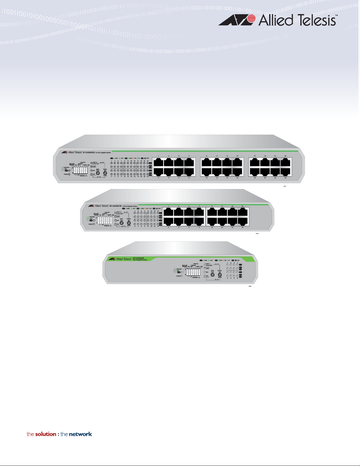
The AT-GS920/24 switch has 24 each 10/100/1000Base-TX twisted pair
ports as shown in Figure 1.
Figure 1. AT-GS920/24 Front Panel
18
Page 19
Chapter 1: Product Description
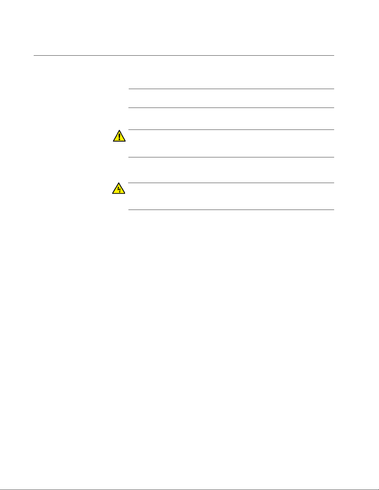
The AT-GS920/24 switch has an internal power supply with a single AC
power supply socket on the rear panel as shown in Figure 2.
x
Figure 2. AT-GS920/24 Rear Panel
AT-GS920/16
Switch
The AT-GS920/16 switch can be installed on a desktop, mounted on a
wall, or in a 19-inch equipment rack. To mount the switch on the wall or an
equipment rack, you must order separate bracket kits. For more
information, see Table 1, “Wall and Rack Mount Brackets” on page 20.
The AT-GS920/16 switch has 16 each 10/100/1000Base-TX twisted pair
ports on the front panel as shown in Figure 3.
x
Figure 3. AT-GS920/16 Front Panel
The AT-GS920/16 switch has an internal power supply with a single AC
power supply socket on the rear panel as shown in Figure 4.
x
AT-GS920/8
Switch
Figure 4. AT-GS920/16 Rear Panel
The AT-GS920/8 switch can be installed on a desktop, mounted on a wall,
or mounted in a 19-inch equipment rack. To mount the switch on the wall
or in an equipment rack, use the brackets that are provided with the
switch.
The AT-GS920/8 switch has 8 each 10/100/1000Base-TX twisted pair
ports as shown in Figure 5.
19
Page 20
GS920 Series Gigabit Ehternet Switch Installation and User’s Guide
x
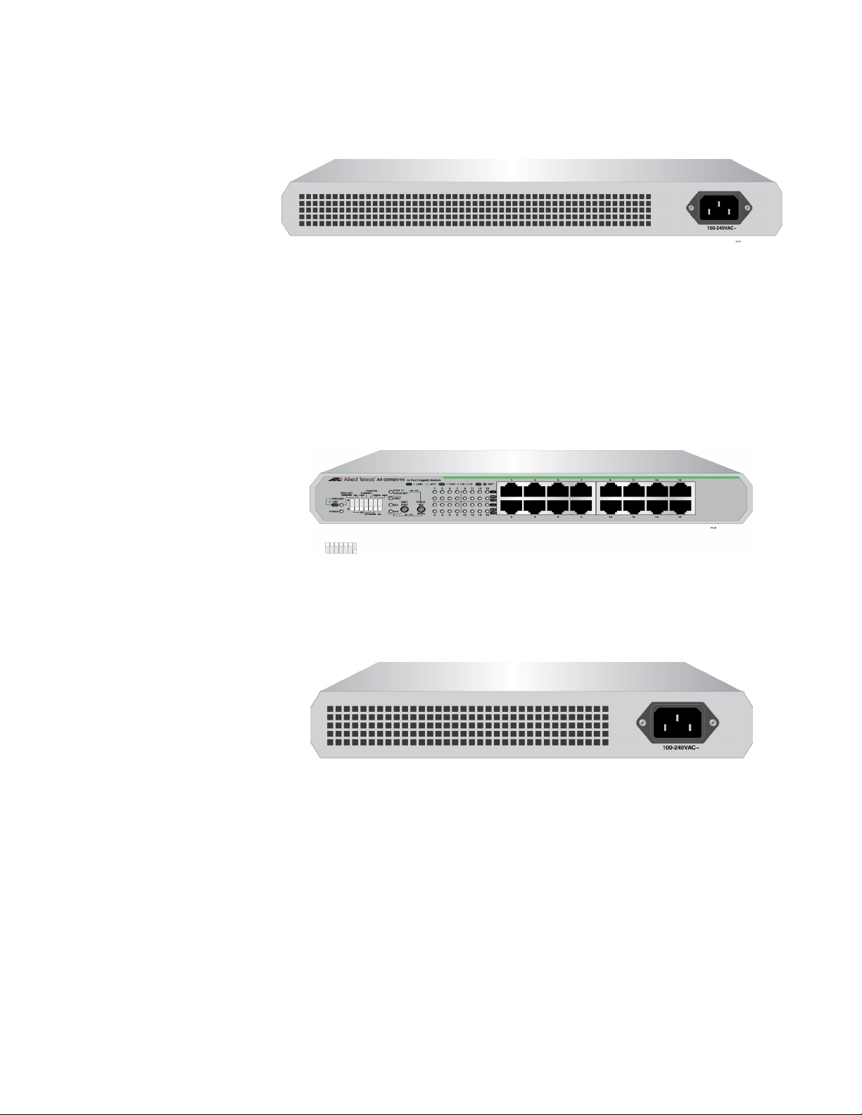
The AT-GS920/8 switch has an internal power supply with a single AC
power supply socket on the rear panel as shown in Figure 6.
x
Figure 5. AT-GS920/8 Front Panel
Figure 6. AT-GS920/8 Rear Panel
Wall and Rack
Mount Brackets
Table 1 shows brackets options for the GS920 Series switches.
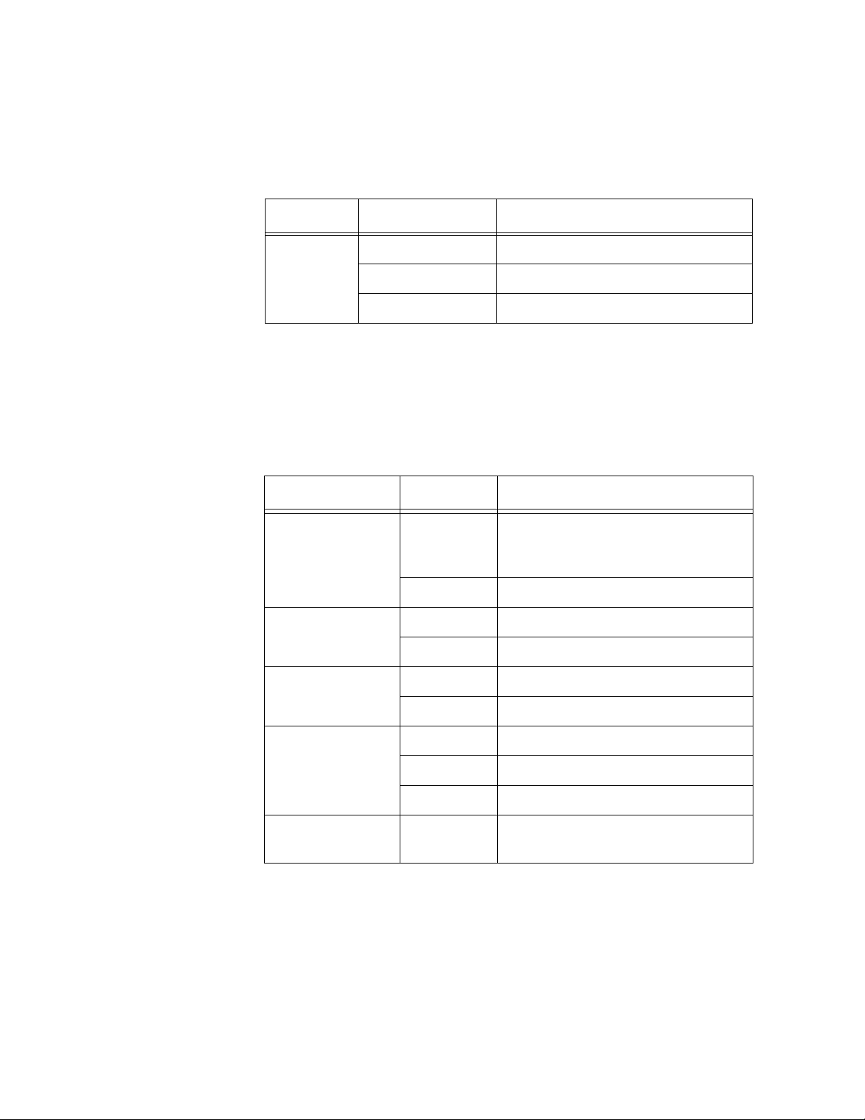
Table 1. Wall and Rack Mount Brackets
Model Wall Mount Rack Mount
AT-GS920/24 Use the Wall/Rack
Mount Kit provided in the
shipping box for all
Use the Wall/Rack Mount
Kit provided in the shipping
box for all installations.
installations except in
Japan.
NOTE: For Japan
installations only, use the
optional AT-BRKT-J22
Wall Mount Kit instead
which must be ordered
separately.
AT-GS920/16 Use AT-BRKT-J23 wall
mount kit.
NOTE: This kit must be
ordered separately.
Optional AT-RKMT-J05
optional 19” rack mount kit.
NOTE: This kit must be
ordered separately.
AT-GS920/8 Use AT-BRKT-J23 wall
mount kit.
NOTE: This kit must be
ordered separately.
Optional AT-RKMT-J08
optional 19” rack mount kit.
NOTE: This kit must be
ordered separately.
20
Page 21

Chapter 1: Product Description
Note
10/100/1000
Base-TX Twisted
Pair Ports
The GS920 Series switches are equipped with multiple
10/100/1000Base-TX twisted pair ports
Connector
All twisted pair ports feature 8-pin RJ-45 connectors. For the port pinouts,
see “RJ-45 Twisted Pair Port Connectors” on page 85.
Speed
The ports are 10Base-T, 100Base-TX, and 1000Base-T compliant and
capable of 10 Mbps, 100 Mbps, and 1000 Mbps speeds. The ports default
configuration is IEEE 802.3u Auto-Negotiation compliant. With
Auto-Negotiation enabled, the switch automatically matches the highest
possible common speed between the switch port and its end-node. For
example, if an end-node is capable of only 10 Mbps, the switch sets the
port connected to the end-node to 10 Mbps.
Alternatively, each port can be manually configured to 10 Mbps, 100
Mbps, and 1000 Mbps via the switches and push buttons. See
“MDI/MDI-X” for the corresponding description of the MDI-X configuration.
Duplex Mode
Each twisted pair port on the switch can operate in either half- or
full-duplex mode at 100/10 Mbps and full-duplex mode only when
operating at 1000 Mbps. The duplex default settings of the twisted pair
ports are IEEE 802.3u-compliant and automatically negotiate the duplex
mode setting.
In order for the switch to automatically set the duplex mode for each
port correctly at 100/10 Mbps, the end-nodes that you connect to the
switch ports also need to be configured for Auto-Negotiation.
Otherwise, a duplex mode mismatch can occur, affecting network
performance. For further information, refer to “Duplex Mode” on
page 26.
With the DIP switches and push buttons, each port can be manually
configured for one of the following duplex modes: Auto-Negotiation,
1000M/Full, 100M/Full, 100M/Half, 10M/Full, 10M/Half.
21
Page 22

GS920 Series Gigabit Ehternet Switch Installation and User’s Guide
Note
Note
MDI/MDI-X
The default configuration for all of the twisted pair ports on the switch is
auto-MDI/MDI-X where the ports automatically configure themselves as
MDI or MDI-X when connected to an end-node. Auto-MDI/MDI-X is in
effect when the ports are configured for Auto-Negotiation or 1000M/FULL.
In this mode, you can use a straight-through twisted pair cable to connect
any network device to a port.
See “Ethernet Port Configuration” on page 72 for the port
configuration procedures.
You can manually force the highest numbered port to fixed MDI by using
one of the front panel push buttons. When all of the ports are configured at
once, then the configuration for all other ports is fixed MDI-X.
When a port is manually configured for a speed of 10M or 100M, then that
port is also configured for fixed MDI-X except in the case of the highest
numbered port, which is set to fixed MDI.
Cabling
Table 2 contains the cabling specifications for the twisted pair ports.
Table 2. Twisted Pair Cabling and Distances
Maximum
Speed Type of Cable
10 Mbps Two-pair Category 3 or better
unshielded twisted pair cable
100 Mbps Two-pair Category 5 or better
unshielded twisted pair cable
1000 Mbps Four-pair Category 5e or better
unshielded twisted pair cable
Operating
Distance
100 m (328 ft)
100 m (328 ft)
100 m (328 ft)
Power Connector The AT-GS920 switches have a single AC power supply socket on the
back panel. Use the AC power cord that is supplied with the switch.
To power the switch ON or OFF, connect or disconnect the power
cord from the switch.
22
Page 23
Configuration Switches and LED Descriptions
Note
The LEDs display status information when the switch is in a Normal
operating mode or in a Configuration mode.
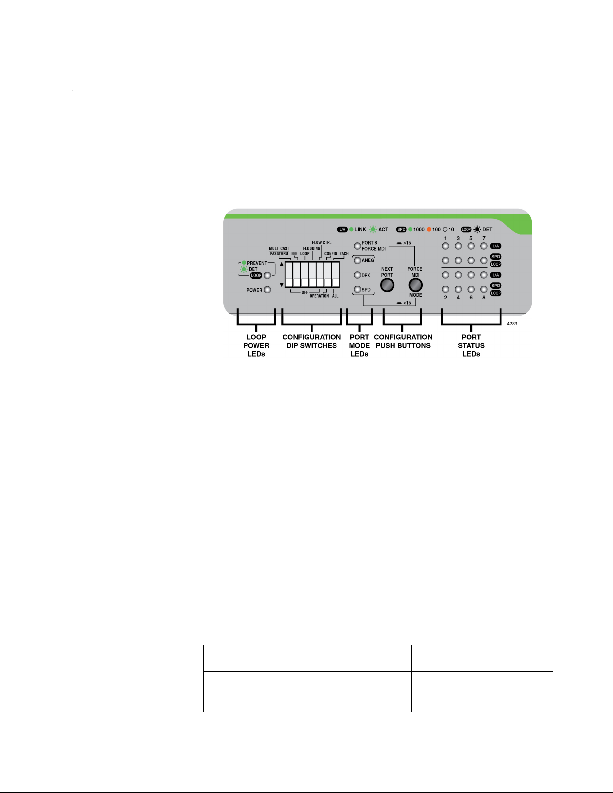
The GS920 Series LEDs and configuration switches are located on the
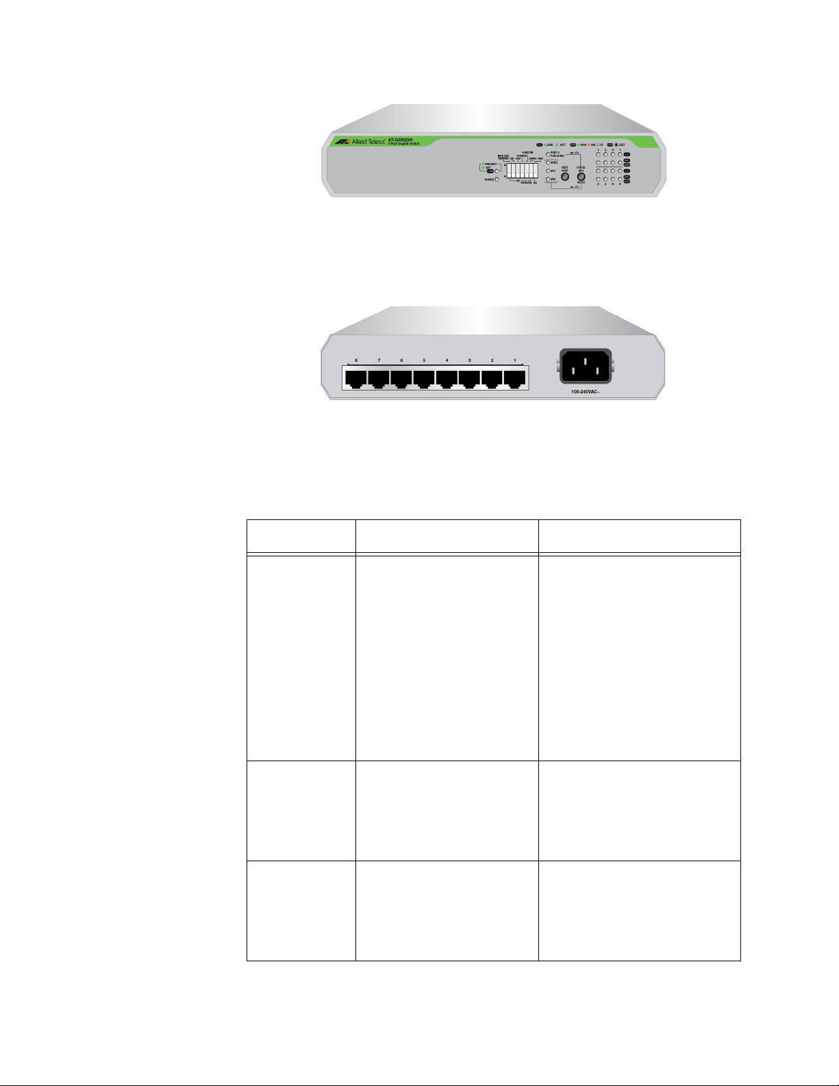
front panel of the chassis. Refer to Figure 7, “AT-GS920/8 Front Panel
Configuration DIP Switches and LEDs” for their locations.
Chapter 1: Product Description
Figure 7. AT-GS920/8 Front Panel Configuration DIP Switches and LEDs
The front panel Configuration switches and LED locations are shown
for the AT-GS920/8 switch. Similar switch and LED layouts can also
be found on the AT-GS920/24 and AT-GS920/16 front panels.
The following tables describe the LED groups on the GS920 Series
switches:
“Power LED”
“Loop Prevention LED” on page 24
“Port Mode LEDs” on page 24
“Port Status LEDs” on page 25
Power LED The Power LED indicates the status of the chassis power being ON or
OFF. See Table 3, “Power LED”.
Table 3. Power LED
LED State Description
PWR
Green ON Power ON
OFF Power OFF
23
Page 24
GS920 Series Gigabit Ehternet Switch Installation and User’s Guide
Loop Prevention
LED
The Loop Prevention LED indicates if the Loop Prevention feature is
enabled or disabled and if a loop condition has been detected and blocked
on one of the Ethernet ports. See Table 4, “Loop Prevention LED”.
Table 4. Loop Prevention LED
LED State Description
Green ON Enable Loop Prevention
LOOP
Prevention
Green Blinking Loop condition detected
OFF Disable Loop Prevention
Port Mode LEDs See “Ethernet Port Configuration” on page 72 for the configuration
procedures and more information.
When the Ethernet ports are being configured, the Port Mode LEDs
indicate their configuration. See Table 5, “Port Mode LEDs”.
Table 5. Port Mode LEDs
LED State Description
Select Enabled - FORCE MDI for
Force MDI
Green ON
a,b
the highest Ethernet port and fixed
MDI-X for all other Ethernet ports.
OFF Select Auto MDI/MDI-X
Auto-Negotiation Green ON Select Enabled - Auto-Negotiation
OFF Select Disabled - Auto-Negotiation
Duplex Green ON Select Full Duplex Mode
OFF Select Half Duplex Mode
Green ON Select 1000M speed
Speed
Amber ON Select 100M speed
OFF Select 10M speed
ALL Mode LEDs Green
Blinking
a. When the port speed is configured for Auto Negotiation or 1000M/Full, the
MODE/FORCE MDI push button affects the FORCE MDI LED as described
above.
b.
When the port speed is configured individually or altogether for 100M or
10M, the respective ports are always configured as follows:
AT-GS920/8: Ports 1-7 => MDI-X, Port 8 => MDI
AT-GS920/16: Ports 1-15 => MDI-X, Port 16 => MDI
AT-GS920/24: Ports 1-23 => MDI-X, Port 24 => MDI
Reset to default indication when
blinking on all 4 MODE LEDs
24
Page 25

Chapter 1: Product Description
Port Status LEDs Two ports status LEDs are assigned to each port. When the switch is in
the Normal operating mode, the upper port LED indicates the Link/Activity
status, and the lower LED indicates the port speed and loop detection
status. When the switch is in the Configuration mode, the upper port LED
is OFF and the lower LED indicates if the specific port is selected to be
configured. See Table 6, “Port Status LEDs for Normal and Configuration
Modes”.
Table 6. Port Status LEDs for Normal and Configuration Modes
Mode
Normal Mode
Port LED
Position
LED State Description
Upper LEDs Link/Activity
SPEED
Lower LEDs
LOOP
Indication
Green ON Valid Link has been established
Green
Transmitting or Receiving Data
Blinking
OFF No Link
Green ON 1000Mbps Link
Amber ON 100Mbps Link
OFF 10Mbps Link or No Link
1000Mbps Link. A loop condition
Green
Blinking
is detected and the port is
automatically blocked by switch to
relieve the loop.
100Mbps or 10Mbps Link. A loop
Amber
Blinking
condition is detected and the port
is automatically blocked by switch
to relieve the loop.
Configuration
Mode
Lower LEDs
a
Green
Blinking
Port Select
Indicates the port is selected and
b
eligible to be configured with front
panel DIP switches.
OFF Port is not selected.
a. The Upper LED for each port is not used in the Configuration Mode.
b. When all of the Lower LEDs are blinking together in the Configuration Mode, then all of the Ethernet ports are
eligible to be configured at once. When only one of the Lower LEDs is blinking, then that port is eligible to be
individually configured.
25
Page 26

GS920 Series Gigabit Ehternet Switch Installation and User’s Guide
Note
AT-GS920 Feature Descriptions
An Ethernet switch interconnects network devices, such as workstations,
printers, routers, and other Ethernet switches, so that they can
communicate with each other by sending and receiving Ethernet frames.
This section discusses the following features:
“Duplex Mode”
“Store and Forward”
“Multicast Frame Pass-Through”
“Energy Efficiency Ethernet (EEE)”
“Loop Prevention”
“Flooding”
“Backpressure and Flow Control”
Duplex Mode Duplex mode refers to how an end node receives and transmits data. If an
end node can receive or transmit data, but not both simultaneously, it is
operating in half-duplex mode. If an end node can both receive and
transmit data simultaneously, the end node is operating in full-duplex
mode. As such an end node capable of operating in full-duplex can handle
data much faster than an end node that can only operate in half-duplex
mode.
Store and
Forward
The twisted pair ports on the GS920 Series switch can operate in half- or
full-duplex mode for 10/100 Mbps. They are IEEE 802.3u-compliant and
use Auto-Negotiation to set the duplex mode setting for you automatically.
In order for a switch port to successfully Auto-Negotiate its duplex
mode with a 10 or 100 Mbps end-node, the end-node should also be
configured for Auto-Negotiation. Otherwise, a duplex mode
mismatch can occur. A switch port using Auto-Negotiation defaults
to half-duplex if it detects that the end-node is not using
Auto-Negotiation. This results in a mismatch if the end-node is
operating at a fixed duplex mode of full-duplex.
The GS920 Series switch uses store-and-forward as the method for
receiving and transmitting frames. When an Ethernet frame is received on
a switch port, the switch does not retransmit the frame out the destination
port until it has received the entire frame and stored the frame in a port
buffer. It then examines the frame to determine if it is a valid frame. Invalid
frames such as fragments or runts are discarded by the switch. This
insures that only valid frames are transmitted out the switch ports and that
damaged frames are not propagated on your network.
26
Page 27

Chapter 1: Product Description
Note
Note
Note
Multicast Frame
Pass-Through
Energy Efficiency
Ethernet (EEE)
The Multicast Frame Pass-Through function includes EAP, BPDU frame
types and others.
When Multicast Frame Pass-Through is enabled, the Flooding
feature must be disabled.
This feature can be enabled or disabled by setting DIP switch # 1
(MULTICAST PASSTHRU). See “Multicast Frame Pass-Through” on
page 61 for the procedure to enable and disable this feature.
The GS920 Series switches support IEEE 802.3az Energy Efficiency
Ethernet (EEE) when the twisted pair ports are operating at a speed of
100Mbps or 1000Mbps. When EEE is enabled on the switch, the power
consumption to keep links at a these speeds is reduced during periods of
low data activity.
When a GS920 Series switch is operating 10Mbps, EEE is not
supported.
This feature can be enabled or disabled by setting DIP switch # 2 (EEE).
See “Energy Efficiency Ethernet (EEE)” on page 64 for the procedure to
enable and disable this feature.
Loop Prevention The GS920 Series switches support Loop Prevention. When a physical
network has more than one path between two endpoints, a network loop
occurs. This results is a broadcast storm which slows all other Ethernet
traffic on the network. With Loop Prevention enabled, the GS920 Series
switches blocks the specific switch port that is associated with the
excessive traffic.
Please refer to Appendix C, “Loop Prevention Feature” on page 95 for a
more detailed explanation of this feature,
Flow Control must be disabled when Loop Prevention is enabled.
Loop Prevention is not supported when Flow Control is also
enabled.
This feature can be enabled or disabled by setting DIP switch # 3 (Loop).
See “Loop Prevention” on page 66 for the procedure to enable and disable
this feature.
27
Page 28

GS920 Series Gigabit Ehternet Switch Installation and User’s Guide
Note
Note
Flooding The Flooding mode allows all received legal frames to be switched
through the GS920 Series switch.
The Flooding mode has a higher priority and takes precedence over
the Multicast Frame Pass-Through feature. If the Multicast Frame
Pass-Through feature is desired, then the Flooding feature must be
disabled.
This feature can be enabled or disabled by setting DIP switch # 4
(Flooding). See “Flooding” on page 68 for the procedure to enable and
disable this feature.
The GS920 series switches DO NOT SUPPORT the combination of
Flooding & Flow Control. If both the flooding and flow control
features are enabled at once, traffic will be stopped by pause
packet.
For example: 1G traffic --> 10Mbps,100Mbps, then 1G traffic will be
10Mbps because of pause packet.
Backpressure and
Flow Control
To maintain the orderly movement of data between the end-nodes, an
Ethernet switch may periodically need to signal an end-node to stop
sending data. This can occur under several circumstances. For example, if
two end-nodes are operating at different speeds, the switch, while
transferring data between the end-nodes, might need to instruct the faster
end-node to stop transmitting data to allow the slower end-node to catch
up. An example of this would be when a server operating at 100 Mbps is
sending data to a workstation operating at only 10 Mbps.
How a switch signals an end-node to stop transmitting data differs
depending on the duplex mode of the end-node and switch port. A twisted
pair port operating in half-duplex mode stops an end-node from
transmitting data by forcing a collision. A collision on an Ethernet network
occurs when two end-nodes attempt to transmit data using the same data
link at the same time. A collision causes an end-node to stop sending
data, wait for a brief period of time, and then retransmit the same data.
Once the switch is ready to receive data again, the switch stops forcing
collisions. This is referred to as backpressure.
A port operating in full-duplex mode uses PAUSE frames, as specified in
the IEEE 802.3x standard, to stop the transmission of data from an
end-node. Whenever the switch wants an end-node to stop transmitting
data, it issues this frame. The frame instructs the end-node to cease
transmission for a period of time specified within the frame. The switch
continues to issue PAUSE frames until it is ready again to receive data
from the end-node. This is referred to as flow control. Refer to Table 7,
“Flow Control - Supported Speeds” on page 29 for Backpressure and Flow
28
Page 29

control support vs. port speed.
Note
Table 7. Flow Control - Supported Speeds
Chapter 1: Product Description
Speed
Configuration
Pause Frame Back Pressure
Auto Negotiation
1G Full Auto
100M Full
100M Half
10M Full
10M Half
This feature can be enabled or disabled by setting DIP switch # 5 (FLOW
CTRL). See “Flow Control” on page 70 for the procedure to enable and
disable this feature.
The GS920 series switches DO NOT SUPPORT the combination of
Flooding & Flow Control. If both the flooding and flow control
features are enabled at once, traffic will be stopped by pause
packet.
For example: 1G traffic --> 10Mbps,100Mbps, then 1G traffic will be
10Mbps because of pause packet.
Not Support Not Support
Not Support Support
Not Support Not Support
Not Support Support
Flow Controllable
Support Support
Support Not Support
29
Page 30

GS920 Series Gigabit Ehternet Switch Installation and User’s Guide
30
Page 31

Chapter 2
Hardware Installation
This chapter contains the following sections:
“Reviewing Safety Precautions” on page 32
“Selecting a Site for the Switch” on page 34
“Planning the Installation” on page 35
“Unpacking the Switch” on page 36
“Installing the Switch on a Table or Desktop” on page 40
“Installing the Switch on a Wall” on page 41
“Installing the Switch in an Equipment Rack” on page 47
“Cabling the Switch” on page 54
“Powering On the Switch” on page 55
31
Page 32

GS920 Series Gigabit Ehternet Switch Installation and User’s Guide
Note
Warning
Warning
Warning
Warning
Caution
Note
Note
Reviewing Safety Precautions
Review the following safety precautions before you begin to install the
switch.
Important: The indicates that translations of the safety statement
are available in the PDF document Translated Safety Statements
posted on the Allied Telesis website at alliedtelesis.com/support.
To prevent electric shock, do not remove the cover. No
user-serviceable parts inside. This unit contains hazardous voltages
and should only be opened by a trained and qualified technician. To
avoid the possibility of electric shock, disconnect electric power to
the product before connecting or disconnecting the cables. E1
Do not work on equipment or cables during periods of lightning
activity. E2
Power cord is used as a disconnection device. To de-energize
equipment, disconnect the power cord. E3
Class I Equipment. This equipment must be earthed. The power
plug must be connected to a properly wired earth ground socket
outlet. An improperly wired socket outlet could place hazardous
voltages on accessible metal parts. E4
Air vents must not be blocked and must have free access to the
room ambient air for cooling. E6
All Countries: Install product in accordance with local and National
Electrical Codes. E8
Operating Temperature. This product is designed for a maximum
ambient temperature of 50 degrees C. E57
32
Page 33
Chapter 2: Hardware Installation
Warning
Warning
Warning
Warning
Warning
An insecurely attached device on a wall may fall and the falling
device may lead to damaging itself or causing injuries. E96
Do not install the device on an unstable wall or a wall affected by
vibration or impact. The device may fall and falling device may lead
to damaging itself or causing injuries. E97
Do not install the device high on a wall. The device may fall and the
falling device may lead to damaging itself or causing injuries. E98
Disconnecting the Device: If the device becomes damaged or you
encounter abnormality with the device, disconnect the power plug
from the AC wall outlet immediately. E100
Use appropriate screws to attach the device and brackets to a
19-inch rack. If a device is installed insecurely in a rack, it may fall,
potentially causing injuries or damage to the device. E104
33
Page 34

GS920 Series Gigabit Ehternet Switch Installation and User’s Guide
Selecting a Site for the Switch
Observe the following requirements when choosing a site for the GS920
Series switch:
– If you plan to install the switch on a table, make sure that the table
is level and secured.
– If you plan to install the switch on a wall, make sure that the wall is
straight and secured.
– If you plan to install the switch in an equipment rack, make sure
that the rack is safely secured to the floor and will not tip over.
Devices in a rack should be installed starting at the bottom, with
the heavier devices near the bottom of the rack.
– The power outlet for the switch should be located near the unit and
should be easily accessible.
– The site should provide for easy access to the ports and the LEDs
on the front of the switch should be easily viewed.
– To allow proper cooling off the switch, air flow around the unit and
through its vents on the side should not be restricted.
– Do not place objects on top of the switch.
– Do not expose the switch to moisture or water.
– Ensure that the site is a dust-free environment.
– Use dedicated power circuits or power conditioners to supply
reliable electrical power to the network devices.
34
Page 35

Planning the Installation
Note
Table 8 contains the cabling specifications for the twisted pair ports.
Speed Type of Cable
Chapter 2: Hardware Installation
Table 8. Twisted Pair Cabling and Distances
Maximum
Operating
Distance
10 Mbps Category 3 or better unshielded twisted
pair cable
100 Mbps Category 5 or unshielded twisted pair
cable
1000 Mbps Four-pair Category 5e unshielded
twisted pair cable
100 m (328 ft)
100 m (328 ft)
100 m (328 ft)
The twisted pair ports on the switch feature Auto-MDI when
operating at either 10/100 Mbps. Each port is individually configured
as MDI or MDI-X when connected to an end-node. Consequently,
you can use a straight-through twisted pair cable when connecting
any network device to a twisted pair port on the switch. A port
operating at 10 or 100 Mbps uses four of the eight strands in twisted
pair wiring.
35
Page 36

GS920 Series Gigabit Ehternet Switch Installation and User’s Guide
Note
Unpacking the Switch
To unpack a GS920 Series switch, perform the following procedure:
1. Remove all components from the shipping package.
Store the packaging material in a safe location. Allied Telesis
recommends that you use the original shipping material to return the
unit to Allied Telesis if required.
2. Place the switch on a level, secure surface.
3. Verify that the hardware components are included in your switch
package.
AT-GS920/24
Shipping
Contents
The contents of the AT-GS920/24 shipping box as shown in Table 9:
Table 9. AT-GS920/24 Shipping Box Contents
Description Illustration
AT-GS920/24
Switch
AC Power cord
Rubber feet
(Set of 4)
Four mounting
screws
36
Page 37

Chapter 2: Hardware Installation
Note
Note
Unpacking the
AT-GS920/24
Bracket Kit
The AT-GS920/24 also comes with the AT-GS920/24 Bracket Kit. Verify
that all hardware components in your Bracket Kit are included as listed in
Table 10.
If you plan to install the AT-GS920/24 on a wall or in an equipment
rack, use the AT-GS920/24 Bracket Kit provided in the shipping box
with the switch.
If you plan to install the AT-GS920/24 on a wall in Japan, you must
order an AT-BRKT-J22 optional wall mount kit separately from the
switch. If you are installing the AT-GS920/24 in an equipment rack in
Japan, use the AT-GS920/24 Bracket Kit provide with the unit.
Table 10. Components in the AT-GS920/24 Bracket Kit
Bracket Description AT-GS920/24
Bracket for the right side
of the switch
Bracket for the left side
of the switch
Extension
Four M3x6mm screws
for attaching the
brackets to the switch
Two M4x6mm screws for
attaching the right side
bracket and extension
37
Page 38

GS920 Series Gigabit Ehternet Switch Installation and User’s Guide
Note
Note
AT-GS920/16
Shipping
Contents
The contents of the AT-GS920/16 shipping box as shown in Table 11:
If you plan to install the AT-GS920/16 on a wall, you must order an
AT-BRKT-J23 optional wall mount kit separately from the switch.
If you plan to install the AT-GS920/16 in an equipment rack, you
must order an AT-RKMT-J05 optional 19” rack mount kit separately
from the switch.
Table 11. AT-GS920/16 Shipping Box Contents
Description Illustration
AT-GS920/16 Switch
AC Power cord
Rubber feet
Four mounting screws
38
Page 39

Chapter 2: Hardware Installation
Note
Note
AT-GS920/8
Shipping
Contents
The contents of the AT-GS920/8 shipping box as shown in Table 12:
If you plan to install the AT-GS920/8 on a wall, you must order an
AT-BRKT-J23 optional wall mount kit separately from the switch.
If you plan to install the AT-GS920/8 in an equipment rack, you must
order an AT-RKMT-J08 optional 19” rack mount kit separately from If
any item is missing or damaged, contact your Allied Telesis sales
representative for assistance.
Table 12. AT-GS920/8 Shipping Box Contents
Description Illustration
AT-GS 9 20/8 Switch
AC Power cord
Rubber feet
Four mounting screws
39
Page 40

GS920 Series Gigabit Ehternet Switch Installation and User’s Guide
Installing the Switch on a Table or Desktop
To install the switch on a table or desktop, perform the following
procedure:
1. Remove all the items from the packaging.
2. Store the packaging material in a safe place.
In the event a problem occurs and you need to return the unit, use as
much of the original shipping material as possible.
3. Install the four rubber feet with the four screws provided on the bottom
of the switch chassis. See Figure 8.
Figure 8. Installation of Rubber Feet
4. Place the switch on a flat and secure surface with the rubber feet firmly
on the table or desktop, leaving a minimum of 4” around the switch for
ventilation.
5. Proceed to “Cabling the Switch” on page 54 for the cable installation.
40
Page 41

Installing the Switch on a Wall
Note
All three AT-GS920 switches can be mounted on a wall.
Chapter 2: Hardware Installation
Guidelines for
Installing the
Switch on a Wall
Items Need for
Wall Installation
Before planning to install the switch on a wall, review the following
guidelines:
– To install the AT-GS920/24 switch, use the brackets included in the
shipping box in all locations except in Japan where you must
purchase the AT-BRKT-J22 Wall Mount Kit separately.
– To install the AT-GS920/16 or AT-GS920/8 switch, you must
purchase the AT-BRKT-J23 wall mount brackets separately.
– Any of the AT-GS920 switch models can be mounted on the wall
with the front panel facing left, right, up or down.
– Before you begin to install the switch, review “Reviewing Safety
Precautions” on page 32.
You need the following items to install the switch on a wall:
–A switch
– One pair of brackets (For more information, see ”Guidelines for
Installing the Switch on a Wall”.)
– Four screws to attach the brackets to a wall
– Four plastic anchors for the screws
– Phillips-head screwdriver
– Pencil
The screws, plastic anchors, Phillip-head screwdriver and pencil are
not included in the shipping box. You must provide these items.
41
Page 42

GS920 Series Gigabit Ehternet Switch Installation and User’s Guide
Note
Wall Installation
of AT-GS920/24
To install the AT-GS920/24 switch on a wall for all installations
everywhere except in Japan, perform the following procedure:
To install the AT-GS920/24 switch on a wall in Japan, see
“AT-GS920/24 Switch Wall Mount Installation” on page 87 for the
installation instructions using the AT-BRKT-J22 Wall Mount Kit
separately.
1. Place all the items from the packaging on a work table.
2. If the rubber feet were previously installed, turn the switch over with
the top side down and remove the rubber feet on the bottom of the
switch using a Phillips-head screwdriver.
Figure 9. Removing Feet From the Chassis Bottom
3. Turn the switch over with the top side up.
4. Orient the brackets against the sides of the switch and secure them to
the switch with the four screws provided as shown in Figure 10.
Figure 10. Attaching the Brackets to the AT-GS920/24 Switch
42
Page 43

Chapter 2: Hardware Installation
Note
5. Have another person hold the switch with the brackets at the wall
location where the switch is to be installed, while you use a pencil to
mark the wall with the locations of the four holes in the brackets. See
Figure 11 as an example.
Figure 11. Marking the Screw Hole Locations
Figure 11 shows the front panel oriented toward the right side.
However, the switch can be mounted on the wall with the front panel
facing left, right, up or down.
6. Pre-drill the marked locations on the wall.
7. Install the four plastic anchors into the wall in the holes drilled in
previous step.
8. Position the switch on the wall and drive screws through the holes to
attach the brackets on the wall. See Figure 12.
x
Figure 12. Driving the Screws through the Holes
43
Page 44

GS920 Series Gigabit Ehternet Switch Installation and User’s Guide
Note
Note
9. Make sure that the two brackets are installed securely.
10. Proceed to “Cabling the Switch” on page 54.
Wall Installation
of AT-GS920/16
or AT-GS920/8
This section explains the procedure for the installation either a
AT-GS910/16 switch or a AT-GS910/8 switch on a wall using the
AT-BRKT-J23 wall mount kit.
You must purchase the AT-BRKT-J23 wall mount brackets
separately.
Unpacking the AT-BRKT-J23 Wall Mount Kit
To unpack the AT-BRKT-J23 wall mount kit, perform the following
procedure:
1. Remove all components from the shipping package.
Store the packaging material in a safe location. You must use the
original shipping material if you need to return the unit to Allied
Telesis.
2. Verify that one pair of brackets is included in your wall mount package
listed in Table 10.
Table 13. Components in the AT-BRKT-J23 Wall Mount Kit
Components
One pair of
brackets
3. If any item is missing or damaged, contact your Allied Telesis sales
representative for assistance.
44
Page 45

Chapter 2: Hardware Installation
Note
Installing a Switch Using the AT-BRKT-J23 Wall Mount Kit
This section shows you steps to install a switch on a wall using the
AT-BRKT-J23 kit. To install the switch on a wall, perform the following
procedure:
1. If the rubber feet were previously installed, turn the switch upside down
and remove them as shown in Figure 13.
Figure 13. Removing the Rubber Feet
2. Orient the brackets against the sides of the switch.
3. Have another person hold the switch with the brackets at the wall
location where the switch is to be installed, while you use a pencil to
mark the wall with the locations of the four holes in the brackets. See
Figure 14 as an example.
AT-BRKT- J23
Figure 14. Marking the Screw Hole Locations
Figure 14 shows the front panel oriented toward the left side.
However, the switch can be mounted on the wall with the front panel
facing left, right, up or down.
45
Page 46

GS920 Series Gigabit Ehternet Switch Installation and User’s Guide
4. Pre-drill the marked locations on the wall at the locations marked in
Step 3.
5. Install the four plastic anchors into the wall in the holes drilled in Step
4.
6. Position brackets on the wall and drive screws through the holes to
attach the brackets on the wall. See Figure 15.
Figure 15. Driving the Screws through the Holes
7. Make sure that the two brackets are installed securely.
8. Slide the switch into the brackets on the wall as shown in Figure 16.
Figure 16. Placing the Switch into the Brackets
9. Proceed to “Cabling the Switch” on page 54.
46
Page 47

Installing the Switch in an Equipment Rack
The AT-GS920 switches can be mounted on a 19-inch equipment rack.
Chapter 2: Hardware Installation
Guidelines for
Installing the
Switch in a Rack
What to Prepare
for Installation in
a Rack
Before installing the switch on an equipment rack, review the following
guidelines:
To install the AT-GS920/24 switch, use the brackets included in the
shipping box.
To install the AT-GS920/16 or AT-GS910/8 switch, you must
purchase the rack mount brackets separately. The AT-RKMT-J05
Rack Mount Kit is for the AT-GS920/16 switch and the
AT-RKMT-J08 Rack Mount Kit is for the AT-GS920/8.
Before you begin to install the switch, review “Reviewing Safety
Precautions” on page 32
You need the following items to install the switch in an equipment rack:
A switch
One pair of brackets (For more information, see ”Guidelines for
Installing the Switch on a Wall” above.)
19-inch equipment rack (not provided)
Four screws for the equipment rack (not provided)
Phillips-head screwdriver (not provided)
Rack Installation
of AT-GS920/24
To install the AT-GS920/24 switch in an equipment rack, perform the
following procedure:
1. Place all the items from the packaging on a work table.
2. Attach the extension to the bracket with the M4x6mm screws using a
Phillips-head screw driver as shown in See Figure 17.
x
Figure 17. Attaching the Extension to the Bracket
47
Page 48

GS920 Series Gigabit Ehternet Switch Installation and User’s Guide
Note
3. If the rubber feet were previously installed, turn the switch upside
down and place it on a table. Remove the rubber feet from the bottom
of the switch using a Phillips-head screwdriver.
4. Turn the switch over.
5. Attached the brackets to the switch with the M3x6mm screws using a
Phillips-head screwdriver. See Figure 19.
x
Figure 18. Removing Rubber Feet
Figure 19. Attaching the Brackets to the Switch
6. Mount the switch in a standard 19-inch equipment rack with four
equipment rack screws as shown in Figure 20.
The screws for an equipment rack are not included in the shipping
box.
Figure 20. Attaching the Switch to an Equipment Rack
7. Proceed to “Cabling the Switch” on page 54.
48
Page 49

Chapter 2: Hardware Installation
Note
Note
Rack Installation
of AT-GS920/16
or AT-GS920/8
To install the AT-GS920/16 or AT-GS920/8 switch in an equipment rack
using the AT-RKMT-J05 or AT-RKMT-J08 rack mount kit respectively,
perform the following procedures:
You must purchase theAT-RKMT-J05 or AT-RKMT-J08 rack mount
kit separately.
Unpacking the AT-RKMT-J05 or AT-RKMT-J08 Rack Mount Kit
To unpack the AT-RKMT-J05 or AT-RKMT-J08 rack mount kit, perform the
following procedure:
1. Remove all components from the shipping package.
Store the packaging material in a safe location. You must use the
original shipping material if you need to return the unit to Allied
Telesis.
2. Verify that all hardware components are included in your rack mount
package listed in Table 10.
Two Short
Brackets
Two
Handles
Two Cable
Brackets
Table 14. Components in Rack Mount Kit
Rack Mount Kit
AT-RKMT-J05 AT-RKMT-J08
49
Page 50

GS920 Series Gigabit Ehternet Switch Installation and User’s Guide
Table 14. Components in Rack Mount Kit (Continued)
AT-RKMT-J05 AT-RKMT-J08
Two Long
Brackets
Eight
M3x6mm
screws
Rack Mount Kit
Eight
M4x6mm
screws
Ten
Tie-wrap
3. If any item is missing or damaged, contact your Allied Telesis sales
representative for assistance.
50
Page 51

Chapter 2: Hardware Installation
Note
Install a AT-GS920/16 or AT-GS920/8 Switch Using the
AT-RKMT-J05 or AT-RKMT-J08 Rack Mount Kit
This section gives the steps to install a switch in an equipment rack using
the AT-RKMT-J05 or AT-RKMT-J08 kit.:
The installation procedures are illustrated using the AT-RKMT-J05
rack mount kit as an example.
1. Place all the items from the packaging on a work table.
2. Remove the rubber feet if previously installed.
3. Attach the handle to the short bracket with M3x6mm screws using a
Phillip-head screw driver as shown in Figure 21.
Figure 21. Attaching Handles to Brackets
4. Attach the short bracket and handle to the long bracket with M4x6mm
screws using a Phillip-head screw driver as shown in Figure 22.
Figure 22. Attaching Brackets to Plates
51
Page 52

GS920 Series Gigabit Ehternet Switch Installation and User’s Guide
Note
5. Attach the cable bracket to the unit that you assembled in Step 4 with
M4x6mm screws using a Phillip-head screw driver as shown in
Figure 23.
Figure 23. Attaching Cable Tray to Plates
6. Turn the switch over and place it on the work table.
7. Attach the units in Step 5 to the switch with M3x6mm screws using a
Phillip-head screw driver as shown in Figure 24.
Figure 24. Attaching the Plates to the Switch
8. Mount the switch in a standard 19-inch equipment rack with four
equipment rack screws as shown in Figure 25.
The screws are not included in the AT-RKMT-J05 rack mount kit.
52
Page 53

Chapter 2: Hardware Installation
Figure 25. Attaching the Switch to Equipment Rack
9. Attach the power cord to the back panel of the switch.
10. Proceed to “Cabling the Switch” on page 54.
53
Page 54

GS920 Series Gigabit Ehternet Switch Installation and User’s Guide
Cabling the Switch
After installing the switch on the desktop, connect twisted pair cables to
the ports on the GS920 Series switch.
When connecting a twisted pair cable to a port, observe the following
guidelines:
– An RJ-45 connector should fit snugly into the port on the switch.
The tab on the connector should lock the connector into place.
– The ports on the switch are configure for auto-MDI/MDI-X out of
the shipping box. You can use a straight-through twisted pair cable
to connect any type of network device to a port on the switch.
– The network should not contain data loops, which can adversely
affect network performance. A data loop exists when two or more
network devices can communicate with each other over more than
one data path.
54
Page 55

Powering On the Switch
Warning
Note
To power on the switch, perform the following procedure:
1. Plug the power cord into the power connector on the back of the
switch.
2. Plug the other end of the power cord into a wall outlet.
Power cord is used as a disconnection device. To de-energize
equipment, disconnect the power cord. E3
Pluggable Equipment. The socket outlet shall be installed near the
equipment and shall be easily accessible. E5
3. The switch LEDs display an initial Power-ON sequence. See
Figure 26.
Chapter 2: Hardware Installation
Figure 26. Initial Power-ON Sequence
55
Page 56

GS920 Series Gigabit Ehternet Switch Installation and User’s Guide
Warning
4. After the Power-ON sequence completes, verify that the POWER LED
is green. If the LED is OFF, see “Troubleshooting” on page 79.
The switch is now powered on and ready for network operations.
Disconnecting the Device: If the device becomes damaged or you
encounter abnormality with the device, disconnect the power plug
from the AC wall outlet immediately. E100
5. If the switch is installed in a rack, use the tie-warps provided to secure
the power cord, as shown in Figure 27.
Figure 27. Securing the Power Cord Using Tie-wraps
56
Page 57

Chapter 3
Switch Configuration
This chapter includes the following topics:
“Configuration Switch and LED Locations” on page 58
“Reset Ports to Factory Default Configuration” on page 59
”Feature Configuration”
– “Multicast Frame Pass-Through” on page 61
– “Energy Efficiency Ethernet (EEE)” on page 64
– “Loop Prevention” on page 66
– “Flooding” on page 68
– “Flow Control” on page 70
”Ethernet Port Configuration”
– “ALL Ports Configuration” on page 73
– “EACH Individual Port Configuration” on page 75
– “MDI/MCI-X Configuration” on page 76
57
Page 58

GS920 Series Gigabit Ehternet Switch Installation and User’s Guide
Configuration Switch and LED Locations
The GS920 Series switch is configured with the DIP switches and push
buttons shown in Figure 28, “Front Panel Configuration Switches and
LEDs”.
Figure 28. Front Panel Configuration Switches and LEDs
58
Page 59

Reset Ports to Factory Default Configuration
The factory default configuration for the speed and duplex settings on all
ports is Auto-Negotiation and Auto MDI/MDI-X. If the switch ports are
configured differently and you want to return to the default configuration,
perform the following procedure:
1. Set DIP switch # 6 (OPERATION/CONFIG) to the UP (CONFIG)
position. See Figure 29. The switch is now in the port configuration
mode.
Chapter 3: Switch Configuration
Figure 29. Setting the Switch to Port Configuration Mode
59
Page 60

GS920 Series Gigabit Ehternet Switch Installation and User’s Guide
Note
2. Set DIP switch # 7 (ALL/EACH) to the DOWN (ALL) position. The
SPD/LOOP port LEDs will continually flash with the DIP switches in
these positions.
3. Push the “NEXT PORT” button for 3 seconds or more. The four MODE
LEDs will begin to flash until the button is released.
4. Set DIP switch # 6 (OPERATION/CONFIG) to the DOWN
(OPERATION) position. The switch is now in the port operational
mode. This new port configuration is now temporarily stored in flash
memory, but is not yet implemented.
5. Turn the power OFF by unplugging the AC power cord and then back
ON again by reconnecting it to the AC outlet on the switch. The new
switch setting is now implemented and effective and the configuration
of the ports is set to the factory default settings of Auto-Negotiation
and Auto MDI/MDI-X.
A recently changed DIP switch setting becomes effective ONLY
after you turn the switch’s AC power OFF and then back ON.
60
Page 61

Feature Configuration
Note
The following features are configurable and are assigned to individual DIP
switches:
”Multicast Frame Pass-Through”
“Energy Efficiency Ethernet (EEE)” on page 64
“Loop Prevention” on page 66
“Flooding” on page 68
“Flow Control” on page 70
Chapter 3: Switch Configuration
Multicast Frame
Pass-Through
DIP switch # 1 enables or disables the Multicast Frame Pass-Through
feature. See Figure 28, “Front Panel Configuration Switches and LEDs” on
page 58 for the DIP switch location on the front panel.
The Flooding feature has priority over Multicast Frame
Pass-Through feature when both are enabled. If you prefer to have
the Multicast Frame Pass-Through feature enabled, the ATI
recommends that you disable the Flooding feature. See “Disabling
Flooding” on page 69 for more information.
Enabling Multicast Frame Pass-Through
Perform the following procedure to enable the Multicast Frame
Pass-Through feature:
1. Set DIP switch # 1 to the UP position to enable this feature. See
Figure 30.
61
Page 62

GS920 Series Gigabit Ehternet Switch Installation and User’s Guide
Note
Figure 30. DIP Switch Setting for Enabling Multicast Frame Pass-Through
2. Turn the power OFF by unplugging the AC power cord and then back
ON again by reconnecting it to the AC outlet on the switch. The new
switch setting is now implemented and effective and the Multicast
Frame Pass-Through feature is enabled.
A recently changed DIP switch setting becomes effective ONLY
after you turn the switch’s AC power OFF and then back ON.
In this configuration, other packet types such as EAP, BPDU and
others are allowed to pass through the switch. The following multicast
addresses are filtered out and are NOT allowed to pass through the
switch:
01-80-C2-00-00-01
01-80-C2-00-00-02
62
Page 63

Chapter 3: Switch Configuration
Note
Note
Disabling Multicast Frame Pass-Through
Perform the following procedure to disable the Multicast Frame
Pass-Through feature:
1. Set DIP switch # 1 to the DOWN position to disable this feature. See
Figure 31.
Figure 31. DIP Switch Settings for Disabling Multicast Frame
Pass-Through
2. Turn the power OFF by unplugging the AC power cord and then back
ON again by reconnecting it to the AC outlet on the switch. The new
switch setting is now implemented and effective and the Multicast
Frame Pass-Through is disabled.
A recently changed DIP switch setting becomes effective ONLY
after you turn the switch’s AC power OFF and then back ON.
When this feature is disabled, the following multicast addresses are
filtered out and are NOT allowed to pass through the switch:
01-80-C2-00-00-00
01-80-C2-00-00-01
01-80-C2-00-00-02
01-80-C2-00-00-03
01-80-C2-00-00-10
01-80-C2-00-00-20
01-80-C2-00-00-21
63
Page 64

GS920 Series Gigabit Ehternet Switch Installation and User’s Guide
Note
Energy Efficiency
Ethernet (EEE)
DIP switch # 2 enables or disables the EEE feature. See Figure 28, “Front
Panel Configuration Switches and LEDs” on page 58 for the DIP switch
location on the front panel.
Enabling EEE
Perform the following procedure to enable the EEE feature:
1. Set DIP switch # 2 to the UP position to enable this feature. See
Figure 32.
Figure 32. DIP Switch Settings for Enabling EEE
2. Turn the power OFF by unplugging the AC power cord and then back
ON again by reconnecting it to the AC outlet on the switch. The new
switch setting is now implemented and effective and the EEE energy
saving behavior is now enabled for all the Ethernet ports.
A recently changed DIP switch setting becomes effective ONLY
after you turn the switch’s AC power OFF and then back ON.
EEE is supported only at 100M/1000M link speed with
Auto-Negotiation enabled. For supported and unsupported speed/link
port configurations, see Table 15, “EEE Support for Port Speed/Link
Configuration” on page 65.
64
Page 65

Chapter 3: Switch Configuration
Note
Table 15. EEE Support for Port Speed/Link Configuration
Supported Speed/Link Unsupported Speed/Link
100M Full Duplex
1000M Auto-Negotiation
100M Auto-Negotiation
100M Half Duplex
10M Full Duplex
10M Half Duplex
Disabling EEE
Perform the following procedure to disable the EEE feature:
1. Set DIP switch # 2 to the DOWN position to disable this feature. See
Figure 33.
Figure 33. DIP Switch Settings for Disabling EEE
2. Turn the power OFF by unplugging the AC power cord and then back
ON again by reconnecting it to the AC outlet on the switch. The new
configuration is now implemented and effective and the EEE feature is
disabled.
A recently changed DIP switch setting becomes effective ONLY
after you turn the switch’s AC power OFF and then back ON.
65
Page 66

GS920 Series Gigabit Ehternet Switch Installation and User’s Guide
Note
Note
Loop Prevention DIP switch # 3 enables or disables the Loop Prevention feature. See
Figure 28, “Front Panel Configuration Switches and LEDs” on page 58 for
the DIP switch location on the front panel.
Enabling Loop Prevention
Perform the following procedure to enable the Loop Prevention feature:
Flow Control must be disabled by when the Loop Prevention feature
is enabled. See “Disabling Flow Control” on page 71
1. Set DIP switch # 3 to the UP position to enable Loop Prevention. See
Figure 34.
Figure 34. DIP Switch Settings for Enabling Loop Prevention
2. Turn the power OFF by unplugging the AC power cord and then back
ON again by reconnecting it to the AC outlet on the switch. The new
switch setting is now implemented and effective and the Loop
Prevention feature is enabled for all the Ethernet ports.
A recently changed DIP switch setting becomes effective ONLY
after you turn the switch’s AC power OFF and then back ON.
The Loop Prevention LED should be a Solid Green or Blinking Green
indicating that the feature is enabled.
66
Page 67

Chapter 3: Switch Configuration
Note
Disabling Loop Prevention
Perform the following procedure to disable the Loop Prevention feature:
1. Set DIP switch # 3 to the DOWN position. See Figure 35.
Figure 35. DIP Switch Settings for Disabling Loop Prevention
2. Turn the power OFF by unplugging the AC power cord and then back
ON again by reconnecting it to the AC outlet on the switch. The new
configuration is now implemented and effective and the Loop
Prevention feature is disabled.
A recently changed DIP switch setting becomes effective ONLY
after you turn the switch’s AC power OFF and then back ON.
The Loop Prevention LED should be OFF indicating that the feature is
disabled.
67
Page 68

GS920 Series Gigabit Ehternet Switch Installation and User’s Guide
Note
Note
Flooding DIP switch # 4 enables or disables the Flooding feature. See Figure 28,
“Front Panel Configuration Switches and LEDs” on page 58 for the DIP
switch location on the front panel.
The Flooding feature has priority over Multicast Frame
Pass-Through feature when both are enabled.
When Flooding is enabled, all packet types including BPDU packets
are allowed to pass through the switch with the following exceptions:
a. Any MAC address containing Ether-type 0x8808 is filtered on the
AT-GS920/8 only.
b. 802.3x Pause Frames are filtered.
ATI recommends disabling the Multicast Frame Pass-Through feature
when the Flooding feature is enabled.
Enabling Flooding
Perform the following procedure to enable the Flooding feature:
1. Set DIP switch # 4 to the UP position to enable this feature. See
Figure 36.
Figure 36. DIP Switch Settings for Enabling Flooding
68
Page 69

Chapter 3: Switch Configuration
Note
Note
2. Turn the power OFF by unplugging the AC power cord and then back
ON again by reconnecting it to the AC outlet on the switch. The new
switch setting is now implemented and effective and Flooding is
enabled on all of the Ethernet ports.
A recently changed DIP switch setting becomes effective ONLY
after you turn the switch’s AC power OFF and then back ON.
Disabling Flooding
Perform the following procedure to disable the Flooding feature:
1. Set DIP switch # 4 to the DOWN position. See Figure 37.
Figure 37. DIP Switch Settings for Disabling Flooding
2. Turn the power OFF by unplugging the AC power cord and then back
ON again by reconnecting it to the AC outlet on the switch. The new
configuration is now implemented and effective and the Flooding
feature is disabled.
A recently changed DIP switch setting becomes effective ONLY
after you turn the switch’s AC power OFF and then back ON.
69
Page 70

GS920 Series Gigabit Ehternet Switch Installation and User’s Guide
Note
Note
Flow Control DIP switch # 5 enables or disables the Flow Control feature. See Figure
28, “Front Panel Configuration Switches and LEDs” on page 58 for the DIP
switch location on the front panel.
Loop Detection must be disabled when the Flow Control feature is
enabled. See “Disabling Loop Prevention” on page 67
Enabling Flow Control
Perform the following procedure to enable the Flow Control feature:
1. Set DIP switch # 5 to the UP position to enable this feature. See
Figure 38.
Figure 38. DIP Switch Settings for Enabling Flow Control
2. Turn the power OFF by unplugging the AC power cord and then back
ON again by reconnecting it to the AC outlet on the switch. The new
switch setting is now implemented and effective and the Flow Control
feature is enabled.
A recently changed DIP switch setting becomes effective ONLY
after you turn the switch’s AC power OFF and then back ON.
70
Page 71

Chapter 3: Switch Configuration
Note
Disabling Flow Control
Perform the following procedure to disable the Flooding feature:
1. Set DIP switch # 5 to the DOWN position to disable this feature. See
Figure 39.
Figure 39. DIP Switch Settings for Disabling Flow Control
2. Turn the power OFF by unplugging the AC power cord and then back
ON again by reconnecting it to the AC outlet on the switch. The new
configuration is now implemented and effective and the Flow Control
feature is disabled.
A recently changed DIP switch setting becomes effective ONLY
after you turn the switch’s AC power OFF and then back ON.
71
Page 72

GS920 Series Gigabit Ehternet Switch Installation and User’s Guide
Note
Note
Note
Ethernet Port Configuration
The following Ethernet port configuration procedures are contained in this
section:
”ALL Ports Configuration”
“EACH Individual Port Configuration” on page 75
The AT-GS920 switch ports can be configured all together or individually
for speed, duplex and MDI/MDI-X. This is done with a combination of the
Configuration DIP switches (#’s 6 and 7) and the configuration push
buttons on the front panel.
When configuring ALL the ports at once, toggling the FORCE MDI/MODE
button for less than 1 second selects a specific speed and duplex setting.
With the ports are specifically configured for either Auto Negotiation or
1000M/Full and the FORCE MDI/MODE button is pushed for more than 1
second, all the ports are set to MDI-X except for the highest numbered
port which is set to MDI.
As part of the ports being configured for 100M or 10M, all the ports
are configured for MDI-X except for the highest numbered port,
which is set to MDI. Pushing the FORCE MDI/MODE button for
more than 1 second does not change these MDI/MDI-X settings
when the ports are configured for these speeds.
When configuring EACH port individually, pushing the FORCE MDI/MODE
button for less than 1 second selects a specific speed and duplex setting
for the port that is selected. When a port is specifically configured for
either Auto Negotiation or 1000M/Full and the FORCE MDI/MODE button
is pressed for more than 1 second then the port is configured for MDI-X
except if it is the highest numbered port which is set to MDI.
When a selected port is configured for 100M or 10M, then that port
is configured for MDI-X except if it is the highest numbered port and
it is set to MDI. Pushing the FORCE MDI/MODE button for more
than 1 second does not change these MDI/MDI-X settings when the
ports are configured to these speeds.
The highest numbered port cannot be forced to MDI-X and the other
ports cannot be forced to MDI.
See Figure 28, “Front Panel Configuration Switches and LEDs” on page
58 for the DIP switch and push button location on the front panel.
72
Page 73

Chapter 3: Switch Configuration
Note
ALL Ports
Configuration
Perform the following procedure to simultaneously set all of the ports to
the same speed and duplex configuration:
1. Set DIP switch # 6 (OPERATION/CONFIG) to the UP (CONFIG)
position. The switch is now in the port configuration mode.
2. Set DIP switch # 7 (ALL/EACH) to the DOWN (ALL) position. All of the
port LEDs will begin to flash indicating that all of the ports are ready to
be configured. See Figure 40.
Figure 40. DIP Switch Settings for Configuring All Ports
3. Push the MODE button for less than 1 second to select a
pre-configured port configuration setting. Figure 41 shows the port
configuration vs. the MODE LED display when you press this button starting with “Auto-Negotiation”. Each time you press this button, the
port configuration will advance through this sequence to the next
pre-configured setting and then repeat as shown. Select the speed and
duplex configuration that you require for all of the ports.
When the ports are set to a fixed speed of 100M or 10M, they are
also configured for Fixed MDI-X except if it is the highest numbered
port which is set to MDI.
73
Page 74

GS920 Series Gigabit Ehternet Switch Installation and User’s Guide
Note
Note
The FORCE_MDI / MODE push button is a dual purpose button.
When it is pressed for less than one second, it advances the
configuration port settings for speed, duplex and MDI/MDI-X. When
it is pressed for more than one second, the configuration of the
highest numbered port is toggled between MDI and MDI-X.
Figure 41. Port Configuration
4. Set DIP switch # 6 (OPERATION/CONFIG) to the DOWN
(OPERATION) position. The switch is in the port operational mode.
This new port configuration is temporarily stored in flash memory, but
is not yet implemented.
5. Turn the power OFF by unplugging the AC power cord and then back
ON again by reconnecting it to the AC outlet on the switch. The new
port configuration for all of the Ethernet ports is implemented and
effective.
This new configuration will ONLY take effect after turning the switch
OFF and then back ON.
74
Page 75
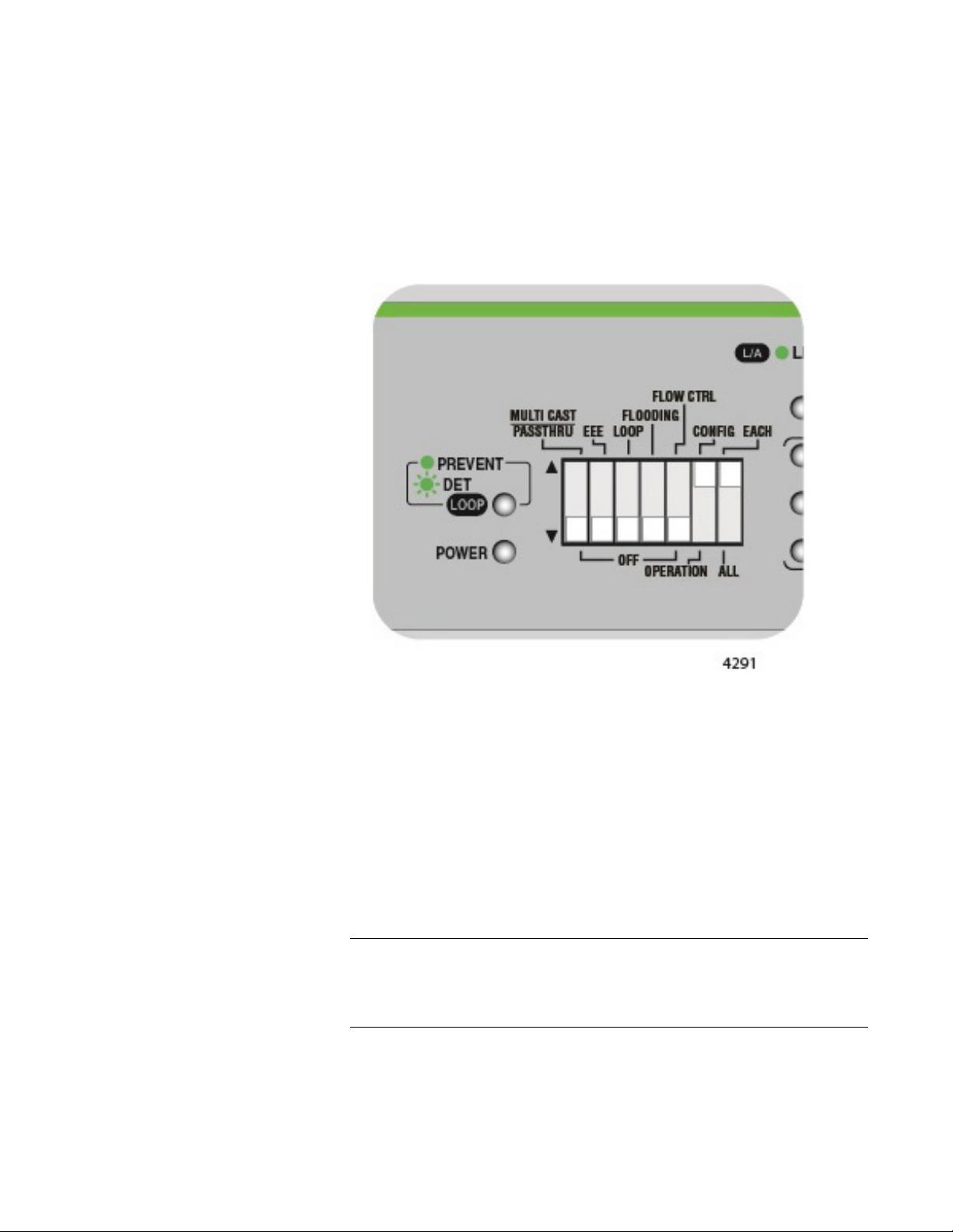
Chapter 3: Switch Configuration
Note
EACH Individual
Port
Configuration
Perform the following procedure to set an individual port to a specific
speed and duplex configuration:
1. Set DIP switch # 6 (OPERATION/CONFIG) to the UP (CONFIG)
position. The switch is now in the port configuration mode.
2. Set DIP switch # 7 (ALL/EACH) to the UP (EACH) position. The SPD/
LOOP LED begins to flash for Port # 1 indicating that this port is ready
to be configured. See Figure 42.
Figure 42. DIP Switch Settings for Configuring An Individual Port
3. If you want to individually configure other ports, press the NEXT PORT
push button to advance to another port indicated by its flashing SPD/
LOOP LED.
4. Push the MODE button for less than 1 second to select a
pre-configured port configuration setting. Figure 41 shows the
configuration setting when you press this button - starting with
“Auto-Negotiation”. Each time you press this button, the port
configuration will advance in this sequence to the next pre-configured
setting. Select the port configuration that you require.
When a port is set to a fixed speed of 100M or 10M, it is also
configured for Fixed MDI-X except if it is the highest numbered port
which is set to MDI.
75
Page 76

GS920 Series Gigabit Ehternet Switch Installation and User’s Guide
Note
Note
5. Repeat Step 3 and Step 4 if you want to configure other ports.
6. After all the ports are individually configured, set DIP switch # 6
(OPERATION/CONFIG) to the DOWN (OPERATION) position. The
switch is now in the port operational mode. This new port configuration
is now temporarily stored in flash memory, but is not yet implemented.
7. Turn the power OFF by unplugging the AC power cord and then back
ON again by reconnecting it to the AC outlet on the switch. The new
new port configurations are now implemented and effective.
This new configuration will ONLY take effect after turning the switch
OFF and then back ON.
MDI/MCI-X
Configuration
When a port’s speed is configured for Auto Negotiation or to 1000M/Full,
the default MDI/MDI-X configuration is Auto MDI/MDI-X. Under these
speed selections, the FORCE MDI push button may be used to force the
configuration of the any of the ports to MDI-X except for configuration of
the highest numbered port to MDI.
When any of the ports are configured for a speed of 100M or 10M,
then they are configured for MDI-X except for the highest numbered
port which is configured for MDI. The FORCE MDI push button is not
functional for the ports where these speeds are selected.
The ports can be configured for Forced MDI or Forced MDI-X all at once or
on an individual basis. Perform the following procedures when using the
FORCE MDI push button:
76
Page 77

Chapter 3: Switch Configuration
Note
Setting ALL Ports to Forced MDI/MDI-X
1. Set DIP switch # 6 (OPERATION/CONFIG) to the UP (CONFIG)
position. The switch is now in the port configuration mode.
2. Set DIP switch # 7 (ALL/EACH) to the DOWN (ALL) position. All of the
port SPD/LOOP LEDs will begin to flash indicating that all of the ports
are ready to be configured. See Figure 43.
Figure 43. DIP Switch Settings for ALL Port Configuration
3. Push the MODE button for more than 1 second to enable or disable
the force MDI/MDI-X feature. The FORCE MDI mode status LED will
be either ON or OFF respectively.
4. After all the ports are configured, set DIP switch # 6 (OPERATION/
CONFIG) to the DOWN (OPERATION) position. The switch is now in
the port operational mode. This new port configuration is now
temporarily stored in flash memory, but is not yet implemented.
5. Turn the power OFF by unplugging the AC power cord and then back
ON again by reconnecting it to the AC outlet on the switch. The new
new port configurations are now implemented and effective.
This new configuration will ONLY take effect after turning the switch
OFF and then back ON.
77
Page 78

GS920 Series Gigabit Ehternet Switch Installation and User’s Guide
Note
Setting Individual Ports to Forced MDI or Forced MDI-X
1. Set DIP switch # 6 (OPERATION/CONFIG) to the UP (CONFIG)
position. The switch is now in the port configuration mode.
2. Set DIP switch # 7 (ALL/EACH) to the UP (EACH) position. The SPD/
LOOP LED begins to flash for Port # 1 indicating that this port is ready
to be configured. See Figure 44.
Figure 44. DIP Switch Settings for Individual Port Configuration
3. Push the MODE button for more than 1 second to enable or disable
this feature. The FORCE MDI mode status LED will be either ON or
OFF respectively for the port you selected.
4. Repeat Step 3 and Step 4 if you want to configure other ports in the
same way.
5. After you have configured all the ports individually, set DIP switch # 6
(OPERATION/CONFIG) to the DOWN (OPERATION) position. The
switch is now in the port operational mode. This new port configuration
is now temporarily stored in flash memory, but is not yet implemented.
6. Turn the power OFF by unplugging the AC power cord and then back
ON again by reconnecting it to the AC outlet on the switch. The new
new port configurations are now implemented and effective.
This new configuration will ONLY take effect after turning the switch
OFF and then back ON.
78
Page 79

Chapter 4
Note
Troubleshooting
This chapter contains information on how to troubleshoot the switch in the
event a problem occurs.
If you are still unable to resolve the problem after following the
instructions in this chapter, contact Allied Telesis Technical Support
for assistance. Refer to “Contacting Allied Telesis” on page 13.
Check the POWER LED on the front of the switch. If the LED is OFF,
indicating that the unit is not receiving power, do the following:
Verify that the power cord is securely connected to the power source
and to the connector on the back panel of the switch.
Verify that the power outlet or power supply has power by connecting
another device to it.
Try connecting the unit to another power source.
Try using a different power cord.
Verify that the voltage from the power source is within the required
levels for your region.
Verify that the L/A LED for each port is green. If an L/A LED is OFF, do the
following:
Verify that the end-node connected to the port is powered ON and is
operating properly.
Verify that the twisted pair cable is securely connected to the port on
the switch and to the port on the end-node.
Ensure that the twisted pair cable does not exceed 100 meters (328
feet).
Verify that you are using the appropriate category of twisted pair cable:
Category 3 or better for 10 Mbps operation, Category 5 for 100 Mbps
operation, and four-pair Category 5e for 1000 Mbps.
79
Page 80

GS920 Series Gigabit Ehternet Switch Installation and User’s Guide
80
Page 81

Appendix A
Technical Specifications
This appendix contains the following sections:
“Physical Specifications”
“Environmental Specifications”
“Safety” on page 82
“Electromagnetic Emissions Certifications” on page 83
“EMS (Electromagnetic Susceptibility) EN55024:2010” on page 84
“Power Specifications” on page 84
“RJ-45 Twisted Pair Port Connectors” on page 85
Physical Specifications
Dimensions:
AT-GS920/8 210 mm x 121 mm x 38 mm
AT-GS920/16 263 mm x 179 mm x 38 mm
AT-GS920/24 341 mm x 210 mm x 44 mm
Weight:
AT-GS920/8 0.8 Kg
AT-GS920/16 1.4 Kg
AT-GS920/24 2.1 Kg
Environmental Specifications
Operating Temperature: 0° C to 50° C (32° F to 122° F)
Storage Temperature: -20° C to 70° C (-4° F to 158° F)
Operating Humidity: 5% to 80% non-condensing
Storage Humidity: 5% to 95% non-condensing
81
Page 82

GS920 Series Gigabit Ehternet Switch Installation and User’s Guide
Safety
60950-1 (cULus) UL, cULus
CE
IEC/EN60950-1 UL-CB
EN60950-1 UL-EU
82
Page 83

Electromagnetic Emissions Certifications
Warning
Appendix A: Technical Specifications
EMI (Electro
Magnetic
Interference)
ICES-003 Class A or
EN55032: 2012/AC:
2013 Class A or B
CISPR 32 (Class B) AT-GS920/8
RCM AS/NZS
CISPR 32: 2013
ANATEL (Class B) AT-GS920/8
(Class B) AT-GS920/8
(Class B) AT-GS920/16
(Class A) AT-GS920/24 US
(Class B) AT-GS920/8
(Class B) AT-GS920/16
B
(Class A) AT-GS920/24 CA
(Class B) AT-GS920/8
(Class B) AT-GS920/16
(Class A) AT-GS920/24 EU
(Class B) AT-GS920/16
(Class A) AT-GS920/24 JP
(Class B) AT-GS920/8
(Class B) AT-GS920/16
(Class A) AT-GS920/24 AU/NZ
(Class B) AT-GS920/16
(Class A) AT-GS920/24 Brazil
Immunity EN55024, EN61000-3-2, EN61000-3-3
Electrical Safety UL 60950-1 (cULus), UL-CB, UL-EU
In a domestic environment this product may cause radio interference
in which case the user may be required to take adequate measures.
E84
83
Page 84

GS920 Series Gigabit Ehternet Switch Installation and User’s Guide
EMS (Electromagnetic Susceptibility) EN55024:2010
IEC 61000-4-2:2009 Electrostatic Discharge
IEC 61000-4-3:2006
+ A1:2008 + A2:2010 RF Radiated Immunity
IEC 61000-4-4:2012 First Transient Burst
IEC 61000-4-5:2014 Surge
IEC 61000-4-6:2014 RF Conducted Immunity
IEC 61000-4-8:2010 Power Frequency Magnetic Field Immunity
IEC 61000-4-11:2004 Short Interruptions and Voltage Variations
IEC 61000-3-2:2014 Harmonic Current Emission
IEC 61000-3-3:2013 Voltage Fluctuations and Flicker
Power Specifications
Model Power Ratings Frequency
AT-GS920/8 100 - 240 VAC, 0.20 A 50/60 Hz
AT-GS920/16 100 - 240 VAC, 0.30 A 50/60 Hz
AT-GS920/24 100 - 240 VAC, 0.40 A 50/60 Hz
84
Page 85

RJ-45 Twisted Pair Port Connectors
8
8
1
1
This section lists the connectors and connector pinouts for the AT-GS920
series switch and its components.
Figure 45 illustrates the physical pin layout to an RJ-45 connector and
port.
Figure 45. RJ-45 Connector and Port Pin Layout
Appendix A: Technical Specifications
Table 16 lists the RJ-45 pin signals when a twisted pair port is operating in
the MDI configuration.
Table 16. MDI Pin Signals (10Base-T or 100Base-TX)
Pin Signal
1TX+
2TX-
3RX+
6RX-
Table 17 lists the RJ-45 port pin signals when a twisted pair port is
operating in the MDI-X configuration.
Table 17. MDI-X Pin Signals (10Base-T or 100Base-TX)
Pin Signal
1RX+
2RX-
3TX+
6TX-
85
Page 86

GS920 Series Gigabit Ehternet Switch Installation and User’s Guide
Table 18 lists the pin signals when a port is operating at 1000 Mbps.
Table 18. Pin Signals (1000 Mbps)
Pin Pair
Signal
Name
11TX+_D1
21TX-_D1
3 2 RX+_D2
43BI+_D3
53BI-_D5
6 2 RX-_D2
74BI+_D4
84BI-_D4
86
Page 87

Appendix B
Note
Note
AT-GS920/24 Switch Wall Mount Installation
This appendix explains the procedures for this installation using the
AT-BRKT-J22 wall mount kit. It contains the following sections:
“Unpacking the AT-BRKT-J22 Wall Mount Kit” on page 88
“Installing a Switch Using the AT-BRKT-J22 Wall Mount Kit” on
page 89
When you are installing the AT-GS920/24 switch in a rack in Japan,
you need to use the AT-BRKT-J22 wall mount kit which must be
purchased separately from the switch.
Before you begin to install the switch using the AT-BRKT-J22 wall
mount kit, review “Reviewing Safety Precautions” on page 32.
87
Page 88

GS920 Series Gigabit Ehternet Switch Installation and User’s Guide
Note
Unpacking the AT-BRKT-J22 Wall Mount Kit
To unpack the AT-BRKT-J22 wall mount kit, perform the following
procedure:
1. Remove all components from the shipping package.
Store the packaging material in a safe location. You must use the
original shipping material if you need to return the unit to Allied
Telesis.
2. Verify that One pair of brackets is included in your wall mount package
listed in Table 19.
Table 19. Components in the AT-BRKT-J22 Wall Mount Kit
Description Components
Two pairs of brackets
3. If any item is missing or damaged, contact your Allied Telesis sales
representative for assistance.
88
Page 89

Chapter : AT-GS920/24 Switch Wall Mount Installation
Note
Installing a Switch Using the AT-BRKT-J22 Wall Mount Kit
This section shows you steps to install a switch on a wall using the
AT-BRKT-J22 kit.
What to Prepare Before installing a switch on a wall, make sure that the following items are
ready.
An AT-BRKT-J22 wall mount kit
Eight screws to attach the brackets to a wall
Eight plastic anchors for the screws
Phillips-head screwdriver
Pencil
Screws and plastic anchors are not included in the shipping box.
You must provide screws that hold the switch securely to the wall.
Installing a
Switch Using the
AT-BRKT-J22
Brackets
To install the switch on a wall, perform the following procedure:
1. If the rubber feet were previously installed, remove them as shown in
Figure 46.
Figure 46. Removing AT-GS920/24 Rubber Feet
2. Orient the brackets against the sides of the switch.
89
Page 90

GS920 Series Gigabit Ehternet Switch Installation and User’s Guide
3. Have another person hold the switch with the brackets at the wall
location where the switch is to be installed. Use a pencil to mark the
wall with the locations of the four holes in the brackets. See Figure 47
as an example.
x
Figure 47. Marking the Screw Hole Locations
4. Pre-drill the marked locations on the wall at the locations marked in
Step 3.
5. Install the four plastic anchors into the wall in the holes drilled in
Step 4.
90
Page 91

Chapter : AT-GS920/24 Switch Wall Mount Installation
6. Position brackets on the wall and drive screws through the holes to
attach the brackets on the wall. See Figure 48.
x
Figure 48. Driving the Screws through the Holes
7. Make sure that the two brackets are installed securely.
8. Slide the switch into the brackets on the wall as shown in Figure 49.
x
Figure 49. Placing the Switch into the Brackets
91
Page 92

GS920 Series Gigabit Ehternet Switch Installation and User’s Guide
9. Place the other two brackets on the top of the switch and mark the
screw hole locations with a pencil as shown in Figure 50.
x
Figure 50. Marking the Screw Hole Locations
10. Remove the two brackets and switch and set aside.
11. Pre-drill the marked locations on the wall at the locations marked in
Step 9.
12. Install the four plastic anchors into the wall in the holes drilled in Step
11.
13. Slide the switch into the bottom brackets and place the other two
brackets on the top of the switch
14. Install the screws through the bracket holes to attach them to the wall.
See Figure 51 on page 93.
92
Page 93

Chapter : AT-GS920/24 Switch Wall Mount Installation
x
Figure 51. Driving the Screws through the Holes
15. Make sure that the switch is installed securely to the wall. Proceed to
“Cabling the Switch” on page 54 and then to “Powering On the Switch”
on page 55
93
Page 94

GS920 Series Gigabit Ehternet Switch Installation and User’s Guide
94
Page 95

Appendix C
Note
Loop Prevention Feature
The following sections are contained in this appendix:
“Guidelines for Loop Prevention” on page 96
“Root Switch” on page 97
“Detecting and Blocking a Loop” on page 99
“Hop Count Limitation” on page 103
You can configure the Loop Prevention feature by following the
steps out lined in the “Switch Configuration” chapter under the
section “Loop Prevention” on page 66.
The GS920 Series switches are equipped with a Loop Prevention feature.
It detects loops and blocks ports in order to reduce negative effects on the
local network while keeping connectivity of devices. Loops in Ethernet
networks can cause broadcast storms that consume network bandwidth
and reduce network performance.
When Loop Prevention is enabled, the switch sends Loop Prevention
frames periodically. A loop is detected in the LAN when the switch
receives the Loop Prevention frame sent from itself. When this occurs, the
Loop Detection selects one of the LAN switches and its port to be blocked.
Once the port is blocked, the following actions take place on the affected
switch:
– The Loop LED starts blinking.
– The LED of the blocked port starts blinking.
When the loop is resolved or the link to the blocked port goes down, the
port is relieved from the blocking state and both the switch Loop LED and
port Loop LED stop blinking.
95
Page 96

GS920 Series Gigabit Ehternet Switch Installation and User’s Guide
Guidelines for Loop Prevention
Here are guidelines for enabling Loop Prevention:
– Loop Prevention does not function properly when Flow Control is
enabled. You Flow Control must disabled when Loop Prevention is
enabled.
– When a loop is detected and a port is blocked, the switch does not
flood packets even when Flooding is enabled.
– A port receives Loop Prevention frames even when the port is
blocked.
– The AT-GS920/8 switch with Loop Prevention-enabled ignores a
Loop Prevention frame if its hop count exceeds 32.
– The AT-GS920/16 and AT-GS920/24 switch with Loop
Prevention-enabled ignores a Loop Prevention frame if its hop
count exceeds 10
– Allied Telesis recommends designing the network with 10 or less
cascade levels when building a Loop Prevention-enabled network.
96
Page 97

Root Switch
Note
Chapter : Loop Prevention Feature
The following topics are contained in this section:
“Root Switch Overview”
“Switch Priority”
“Root Switch”
“Non-root Switch”
“Examples of Selecting a Root Switch” on page 98
Root Switch
Overview
In a LAN topology with multiple GS920 Series switches, one of the
switches is elected to be the root switch for the Loop Prevention feature.
Initially, all of the GS920 Series switches are root switches. They
broadcast Loop Prevention frames to each other and then compare their
relative switch priorities. The switch with the highest switch priority is
selected to be the root switch. If multiple switches have the same highest
switch priority, the switch with the smallest MAC address becomes the root
switch.
Switch Priority Table 20 shows the switch priorities specified for each GS920 Series
model.
Table 20. Switch Priority
Model Switch Priority
AT-GS920/8 Higher
AT-GS920/16
AT-GS920/24
Lower
The AT-GS920/8 switch has higher priority than the AT-GS920/16
and AT-GS920/24 switches.
Root Switch Once a switch is assigned as the root switch, it is responsible for sending
out Loop Prevention frames. A loop condition exists if the root switch
receives a Loop Prevention frame that it generates itself. Once a loop is
detected, the root switch determines which switch/port to block within the
LAN to prevent the loop.
Non-root Switch If a switch is not selected as the Loop Prevention root switch, then it is a
non-root switch. A non-root switch updates the hop count in the Loop
Prevention frames before forwarding them. It also maintains a timer for
each of the switch’s ports.
97
Page 98

GS920 Series Gigabit Ehternet Switch Installation and User’s Guide
When receiving a Loop Prevention frame at a port, the switch sets the port
timer to 16 seconds. The timer decreases every second. When another
Loop Prevention frame is received at the port, the switch refreshes the
port timer again to 16 seconds. If all of the switch’s port timers reach zero,
then the switch interprets the situation as a topology change where the
root switch no longer is present. The non-root switch changes itself back
to a root switch and begins to broadcast Loop Prevention frames which
starts a new selection process for a new root switch.
Examples of
Selecting a Root
Switch
Root Switch Based on Highest Priority
In the example shown in Figure 52, Switch A is elected as the root switch
because this switch has the highest priority.
x
Figure 52. Case 1: Selecting a Root Switch
Root Switch Based on Highest Priority/Lowest MAC Address Value
In the example shown in Figure 53, Switch A has a higher priority than
Switch C. Switch A and Switch B have the same switch priority. Since
Switch A’s MAC address is smaller than Switch B’s, Switch A is elected as
the root switch.
Figure 53. Case 2: Selecting a Root Switch
98
Page 99

Chapter : Loop Prevention Feature
Detecting and Blocking a Loop
The following topics are contained in this section:
“Loop Detection”
“Blocked Port Selection Criteria”
“Port Blocked Within a LAN” on page 100
“Port Blocked on One Switch” on page 101
“Blocking a Port Affected by an External Loop” on page 102
Loop Detection Loop Prevention detects a loop in a LAN with using Loop Prevention
frames.These frames are sent from the root switch to all the non-root
switches. If the root switch receives a Loop Prevention frame that it
generated, then a loop is detected. The Loop Prevention feature then
decides which port in the LAN is to be blocked. The blocked port stops
receiving and forwarding all data traffic except for the Loop Prevention
frames.
Blocked Port
Selection Criteria
After a loop is detected in the LAN, Loop Prevention selects a specific port
for blocking by applying the following rules in order of precedence:
1. The port with the largest hop count from the root switch
2. Among the ports with the same hop count, the port that is connected to
the switch with the lowest switch priority
3. Among the ports with the same hop count and switch priority, the port
on the switch with the largest MAC address
4. Among the ports with the same hop count and on the same switch:
– For the AT-GS920/8 switch, a port with the smaller port number
– For the AT-GS920/16 and AT-GS920/24 switches, a port with the
larger port number
99
Page 100

GS920 Series Gigabit Ehternet Switch Installation and User’s Guide
Port Blocked
Within a LAN
When a loop is detected in the example shown in Figure 54, Port 8 on the
Switch C is blocked to relieve the loop. This port has the largest hop count
from the root switch.
Ax
Figure 54. Case 1: Selecting a Port to be Blocked
When a loop is detected in the example shown in Figure 55, Port 1 on the
Switch D is blocked to relieve the loop. Port 1 and Port 9 on Switch D have
the same hop count, but Port 1 is blocked because the switch priority of
Switch C where Port 1 is linked is lower than the switch priority of Switch B
where Port 9 is linked.
Ax
Figure 55. Case 2: Selecting a Port to be Blocked
100
 Loading...