

Page 1
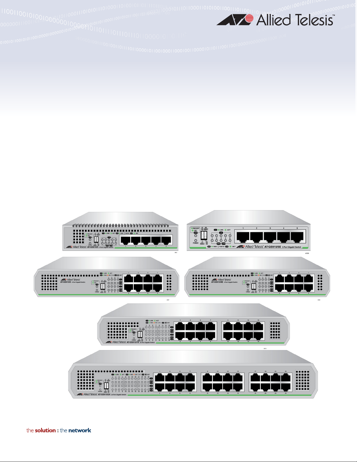
GS910 Series
GIGABIT ETHERNET UNMANAGED SWITCHES
AT-GS910/5
AT-GS910/5E
AT-GS910/8
AT-GS910/8E
AT-GS910/16
AT-GS910/24
Installation and User’s Guide
613-002143 Rev. B
Page 2

Copyright 2016 Allied Telesis, Inc.
All rights reserved. No part of this publication may be reproduced without prior written permission from Allied Telesis, Inc.
Microsoft and Internet Explorer are registered trademarks of Microsoft Corporation. Netscape Navigator is a registered
trademark of Netscape Communications Corporation. All other product names, company names, logos or other
designations mentioned herein are trademarks or registered trademarks of their respective owners.
Allied Telesis, Inc. reserves the right to make changes in specifications and other information contained in this document
without prior written notice. The information provided herein is subject to change without notice. In no event shall Allied
Telesis, Inc. be liable for any incidental, special, indirect, or consequential damages whatsoever, including but not limited to
lost profits, arising out of or related to this manual or the information contained herein, even if Allied Telesis, Inc. has been
advised of, known, or should have known, the possibility of such damages.
Page 3

Electrical Safety and Emissions
Note
Note
Standards
This section contains the following:
“US Federal Communications Commission”
“Industry Canada”
“Emissions, Immunity and Electrical Safety Standards” on page 4
“Translated Safety Statements” on page 4
US Federal Communications Commission
Radiated Energy
This equipment has been tested and found to comply with the limits for a Class A digital device
pursuant to Part 15 of FCC Rules. These limits are designed to provide reasonable protection
against harmful interference when the equipment is operated in a commercial environment.
This equipment generates, uses, and can radiate radio frequency energy and, if not installed
and used in accordance with this instruction manual, may cause harmful interference to radio
communications. Operation of this equipment in a residential area is likely to cause harmful
interference in which case the user will be required to correct the interference at his own
expense.
Modifications or changes not expressly approved of by the manufacturer or the FCC, can void
your right to operate this equipment.
Industry Canada
Radiated Energy
This Class A digital apparatus complies with Canadian ICES-003.
Cet appareil numérique de la classe A est conforme à la norme NMB-003 du Canada.
3
Page 4

Emissions, Immunity and Electrical Safety Standards
Warning
RFI Emissions FCC Class A, CISPR 22 Class A, CISPR 32 Class A, EN55022 Class A,
EN55032 Class A, VCCI, ICES-3(A)/NMB-3(A)
In a domestic environment this product may cause radio interference in which case the user
may be required to take adequate measures. E84
EMC (Immunity) EN55024, EN61000-3-2, EN61000-3-3
Electrical Safety UL60950-1 (
CULUS
), UL-CB, UL-EU
Translated Safety Statements
Important: The indicates that translations of the safety statement are available in the PDF
document Translated Safety Statements posted on the Allied Telesis website at
alliedtelesis.com/support.
4
Page 5

Contents
Preface ..................................................................................................................................................................................7
Safety Symbols Used in this Document ..........................................................................................................................8
Contacting Allied Telesis .................................................................................................................................................9
Chapter 1: Product Description ........................................................................................................................................11
Overview .......................................................................................................................................................................12
AT-GS910/5 Switch................................................................................................................................................12
AT-GS910/5E Switch .............................................................................................................................................13
AT-GS910/8 Switch................................................................................................................................................14
AT-GS910/8E Switch .............................................................................................................................................14
AT-GS910/16 Switch..............................................................................................................................................15
AT-GS910/24 Switch..............................................................................................................................................16
Wall and Rack Mount Brackets ..............................................................................................................................16
LEDs ......................................................................................................................................................................17
10/100/1000 Base-TX Twisted Pair Ports ..............................................................................................................18
Power Connector ...................................................................................................................................................19
Key Features .................................................................................................................................................................20
Ethernet Switching Basics.............................................................................................................................................21
Duplex Mode ..........................................................................................................................................................21
Store-and- Forward ................................................................................................................................................21
Backpressure and Flow Control ..................................................................................................
Loop Prevention ............................................................................................................................................................23
Examples with Multiple Loop Prevention Switches ................................................................................................23
Examples with Loop Prevention and Regular Switches .........................................................................................24
Examples within a Loop Prevention Switch............................................................................................................25
Guidelines for Loop Prevention ..............................................................................................................................26
Enabling Loop Protection .......................................................................................................................................26
Disabling Loop Protection ......................................................................................................................................26
Energy Efficiency Ethernet (EEE) .................................................................................................................................27
...........................21
Chapter 2: Installation .......................................................................................................................................................29
Reviewing Safety Precautions.......................................................................................................................................30
Selecting a Site for the Switch.......................................................................................................................................32
Planning the Installation ................................................................................................................................................33
Unpacking the Switch....................................................................................................................................................34
Installing the Switch on a Table or Desktop ..................................................................................................................36
Installing the Switch on a Wall.......................................................................................................................................37
Guidelines for Installing the Switch on a Wall ........................................................................................................37
What to Prepare for Installation with Brackets .......................................................................................................39
Installing the AT-GS910/5, AT-GS910/8, or AT-GS910/8E Switch on a Wall ........................................................39
Installing the AT-GS910/16 Switch on a Wall....................................................................................
Installing the AT-GS910/24 Switch on a Wall.........................................................................................................41
Installing the Switch in an Equipment Rack...................................................................................................................44
Guidelines for Installing the Switch in a Rack ........................................................................................................44
What to Prepare for Installation in a Rack..............................................................................................................44
Installing the AT-GS910/8 or AT-GS910/8E Switch in a Rack ...............................................................................44
Installing the AT-GS910/16 Switch in a Rack.........................................................................................................44
Installing the AT-GS910/24 Switch in a Rack.........................................................................................................46
Cabling the Switch.........................................................................................................................................................48
Powering On the Switch ................................................................................................................................................49
Chapter 3: Installation Using the AT-BRKT-J23 Wall Mount Kit ...................................................................................51
.....................39
5
Page 6

Contents
Reviewing Safety Precautions.......................................................................................................................................52
Unpacking the AT-BRKT-J23 Wall Mount Kit ................................................................................................................53
Installing a Switch Using the AT-BRKT-J23 Wall Mount Kit ..........................................................................................54
What to Prepare .....................................................................................................................................................54
Installing a Switch Using the Wall Mount Kit ..........................................................................................................54
Chapter 4: Installation Using the AT-RKMT-J08 Rack Mount Kit ..................................................................................57
Reviewing Safety Precautions.......................................................................................................................................58
Unpacking the AT-RKMT-J08 Rack Mount Kit ..............................................................................................................59
Installing a Switch Using the AT-RKMT-J08 Rack Mount Kit ........................................................................................61
What to Prepare .....................................................................................................................................................61
Installing a Switch Using the Rack Mount Kit .........................................................................................................61
Chapter 5: Troubleshooting ..............................................................................................................................................65
Appendix A: Technical Specifications .............................................................................................................................67
Physical Specifications ..................................................................................................................................................67
Environmental Specifications.........................................................................................................................................67
Safety and Electromagnetic Emissions Certifications....................................................................................................68
Power Specifications .....................................................................................................................................................68
RJ-45 Twisted Pair Port Connectors .............................................................................................................................69
6
Page 7

Preface
This manual is the installation and user’s guide for the GS910 Series
Gigabit Ethernet Unmanaged Switches. The switch models included in this
manual are:
AT-GS910/5
AT-GS910/5E
AT-GS910/8
AT-GS910/8E
AT-GS910/16
AT-GS910/24
This Preface contains the following sections:
“Safety Symbols Used in this Document” on page 8
“Contacting Allied Telesis” on page 9
7
Page 8
GS910 Series Gigabit Ehternet Unmanaged Switch Installation and User’s Guide
Note
Caution
Warning
Safety Symbols Used in this Document
This document uses the following conventions:
Notes provide additional information.
Cautions inform you that performing or omitting a specific action
may result in equipment damage or loss of data.
Warnings inform you that performing or omitting a specific action
may result in bodily injury.
8
Page 9

Contacting Allied Telesis
If you need assistance with this product, you may contact Allied Telesis
technical support by going to the Support & Services section of the Allied
Telesis web site at www.alliedtelesis.com/support. You can find links for
the following services on this page:
24/7 Online Support - Enter our interactive support center to
search for answers to your questions in our knowledge database,
check support tickets, learn about Return Merchandise
Authorization (RMA), and contact Allied Telesis technical experts.
USA and EMEA phone support - Select the phone number that
best fits your location and customer type.
Hardware warranty information - Learn about Allied Telesis
warranties and register your product online.
Replacement Services - Submit an RMA request via our interactive
support center.
Preface
Documentation - View the most recent installation guides, user
guides, software release notes, white papers and data sheets for
your product.
Software Updates - Download the latest software releases for your
product.
For sales or corporate contact information, go to
www.alliedtelesis.com/purchase and select your region.
9
Page 10

GS910 Series Gigabit Ehternet Unmanaged Switch Installation and User’s Guide
10
Page 11

Chapter 1
Product Description
This chapter contains the follows sections:
“Overview” on page 12
“Key Features” on page 20
“Ethernet Switching Basics” on page 21
“Loop Prevention” on page 23
“Energy Efficiency Ethernet (EEE)” on page 27
11
Page 12
GS910 Series Gigabit Ehternet Unmanaged Switch Installation and User’s Guide
Overview
The GS910 Series Gigabit Ethernet Switch is an eco-friendly unmanaged
Gigabit Ethernet switch with 10/100/1000 Mbps twisted-pair ports. The
GS910 series switch provides a simple solution to integrate 10, 100, and
1000Mbps devices that exist in your network and expand the network to
Gigabit speed.
The eco-friendly feature automatically saves power consumption on each
port when the port has not established a link. In addition, the switch does
not require software configuration or management.
The GS910 Series Gigabit Ethernet Switch includes the following models:
“AT-GS910/5 Switch”
“AT-GS910/5E Switch”
“AT-GS910/8 Switch” on page 14
“AT-GS910/8E Switch” on page 14
AT-GS910/5
Switch
“AT-GS910/16 Switch” on page 15
“AT-GS910/24 Switch” on page 16
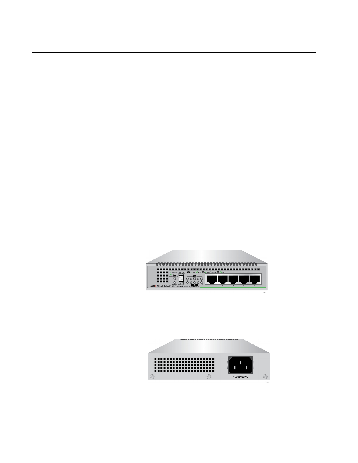
The AT-GS910/5 switch has five 10/100/1000Base-TX twisted pair ports
on the front panel as shown in Figure 1.
x
Figure 1. AT-GS910/5 Front Panel
The AT-GS910/5 switch has an internal power supply with a single AC
power supply socket on the rear panel as shown in Figure 2.
x
Figure 2. AT-GS910/5 Rear Panel
12
Page 13
Chapter 1: Product Description
Note
Note
The AT-GS910/5 switch can be installed on a desktop or mounted on a
wall. To mount the switch on a wall, use the AT-BRKT-J23 wall mount
brackets.
The AT-BRKT-J23 wall mount brackets are not included in the
shipping box. You must purchase them separately.
AT-GS910/5E
Switch
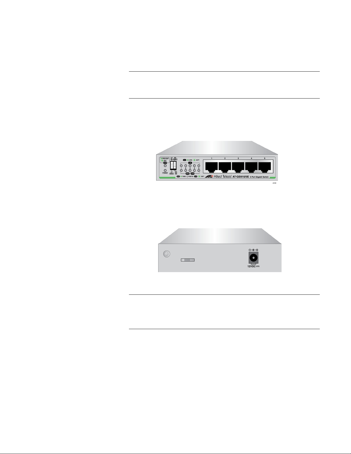
The AT-GS910/5E switch has five 10/100/1000Base-TX twisted pair ports
on the front panel as shown in Figure 3. The switch is installed on a
desktop only.
x
Figure 3. AT-GS910/5E Front Panel
The AT-GS910/5E switch has an external power supply with a single DC
power supply socket on the rear panel as shown in Figure 4.
x
Figure 4. AT-GS910/5E Rear Panel
The AT-GS910/5E power receptacle has a twist-and-lock barrel,
which is locked by turning the power cord clockwise one-quarter
turn.
13
Page 14
GS910 Series Gigabit Ehternet Unmanaged Switch Installation and User’s Guide
Note
AT-GS910/8
Switch
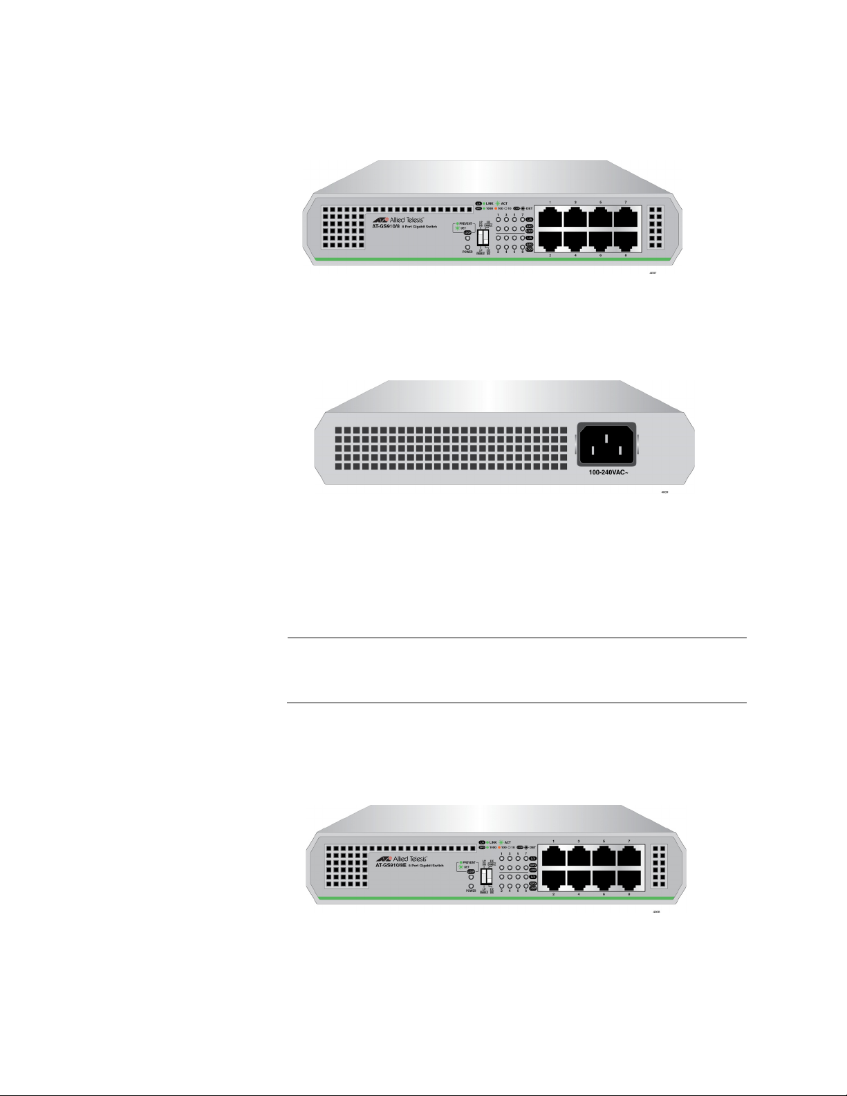
The AT-GS910/8 switch has eight 10/100/1000Base-TX twisted pair ports
on the front panel as shown in Figure 5.
x
Figure 5. AT-GS910/8 Front Panel
The AT-GS910/8 switch has an internal power supply with a single AC
power supply socket on the rear panel as shown in Figure 6.
x
AT-GS910/8E
Switch
Figure 6. AT-GS910/8 Rear Panel
The AT-GS910/8 switch can be installed on a desktop, mounted on a wall,
or mounted in a 19-inch equipment rack. To mount the switch on a wall,
use the AT-BRKT-J23 wall mount brackets. To install the switch in an
equipment rack, use the AT-RKMT-J08 rack mount brackets.
The AT-BRKT-J23 and AT-RKMT-J08 brackets are not included in
the shipping box. You must purchase them separately.
The AT-GS910/8E switch has eight 10/100/1000Base-TX twisted pair
ports on the front panel as shown in Figure 7. The switch is installed on a
desktop only.
x
Figure 7. AT-GS910/8E Front Panel
14
Page 15
Chapter 1: Product Description
Note
Note
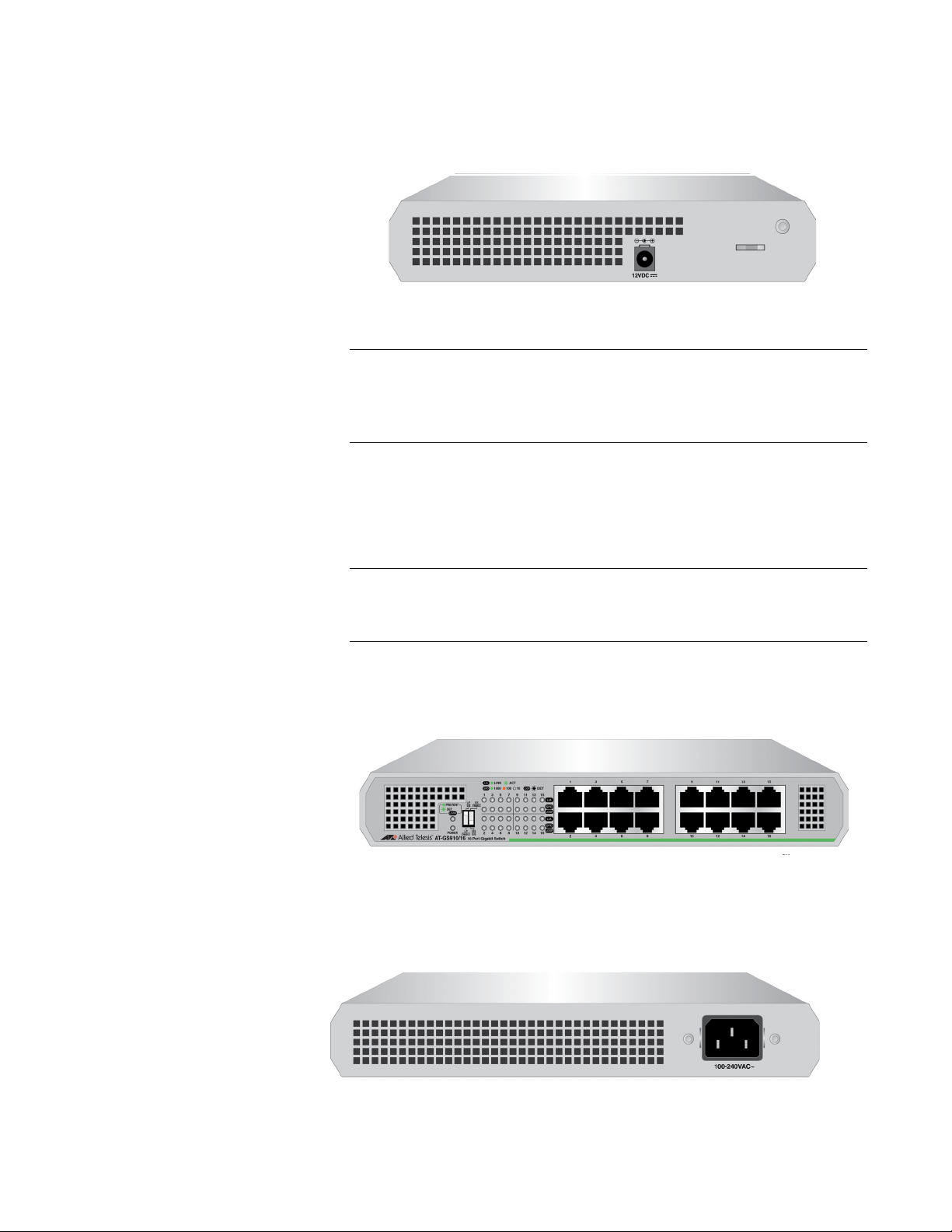
The AT-GS910/8E switch has an external power supply with a single DC
power supply socket on the rear panel as shown in Figure 8.
x
Figure 8. AT-GS910/8E Rear Panel
The AT-GS910/8E power receptacle has a twist-and-lock barrel
which is locked by turning the power cord clockwise one-quarter
turn.
The AT-GS910/8E switch can be installed on a desktop, mounted on a
wall, or mounted in a 19-inch equipment rack. To mount the switch on a
wall, use the AT-BRKT-J23 wall mount brackets. To install the switch in an
equipment rack, use the AT-RKMT-J08 rack mount brackets.
AT-GS910/16
Switch
The AT-BRKT-J23 and AT-RKMT-J08 brackets are not included in
the shipping box. You must purchase them separately.
The AT-GS910/16 switch has 16 10/100/1000Base-TX twisted pair ports
on the front panel as shown in Figure 9.
x
Figure 9. AT-GS910/16 Front Panel
The AT-GS910/16 switch has an internal power supply with a single AC
power supply socket on the rear panel as shown in Figure 10.
x
Figure 10. AT-GS910/16 Rear Panel
15
Page 16
GS910 Series Gigabit Ehternet Unmanaged Switch Installation and User’s Guide
The AT-GS910/16 switch can be installed on a desktop, mounted on a
wall, or mounted in a 19-inch equipment rack. To mount the switch on the
wall or in an equipment rack, use the brackets that come with the switch.
AT-GS910/24
Switch
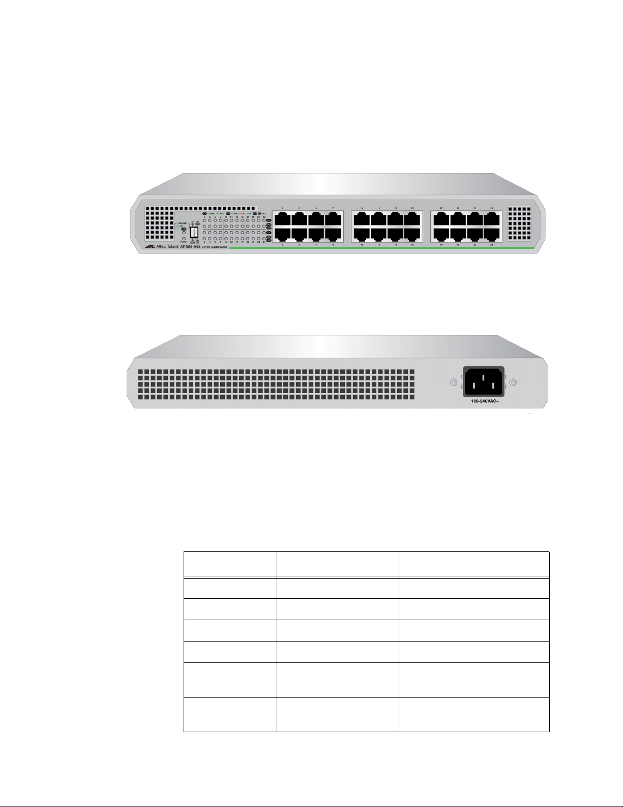
The AT-GS910/24 switch has 24 10/100/1000Base-TX twisted pair ports
on the front panel as shown in Figure 11.
x
Figure 11. AT-GS910/24 Front Panel
The AT-GS910/24 switch has an internal power supply with a single AC
power supply socket on the rear panel as shown in Figure 12.
x
Wall and Rack
Mount Brackets
Figure 12. AT-GS910/24 Rear Panel
The AT-GS910/24 switch can be installed on a desktop, mounted on a
wall, or mounted in a 19-inch equipment rack. To mount the switch on the
wall or in an equipment rack, use the brackets that come with the switch.
Table 1 shows brackets options for the GS910 series switches.
Table 1. Wall and Rack Mount Brackets
Model Wall Mount Rack Mount
AT-GS910/5 AT-BRKT-J23 N/A
AT-GS910/5E N/A N/A
AT-GS910/8 AT-BRKT-J23 AT-RKMT-J08
AT-GS910/8 AT-BRKT-J23 AT-RKMT-J08
AT-GS910/16 The brackets in the
shipping box
AT-GS910/24 The brackets in the
shipping box
The brackets in the
shipping box
The brackets in the
shipping box
16
Page 17

Chapter 1: Product Description
LEDs The LEDs on the front panel of the GS910 series switch display status
information.
LEDs for the AT-GS910/5 and AT-GS910/5 E Switches
Table 2 describes the LEDs on the AT-GS910/5 and AT-GS910/5E
switches.
Table 2. LEDs for the AT-GS910/5 and AT-GS910/5E
LED State Description
POWER Green The switch is powered ON and operating
normally.
Off The switch is not receiving power.
LOOP Green The Loop Prevention is enabled.
Blinking
Green
Off The Loop Prevention is disabled.
L/A Green A valid link is established on the port.
Blinking
Green
Off No link is established.
SPD/
LOOP
Green The port is operating at 1000Mbps.
Off The port is operating at 10/100Mbps or no link
Blinking
Green
A loop has been detected and the switch
blocks the looped port to stop the loop.
Frames are being transmitted/received on the
port.
is established.
A loop is detected while the port is operating at
10/100/1000Mbps. The switch blocks the
looped port to stop the loop.
LEDs for the AT-GS910/8, AT-GS910/8E, AT-GS910/16, and
AT-GS910/24 Switches
Table 3 on page 18 describes the LEDs on the AT-GS910/8,
AT-GS910
/8E, AT-GS910/16, and AT-GS910/24 switches.
17
Page 18

GS910 Series Gigabit Ehternet Unmanaged Switch Installation and User’s Guide
Table 3. LEDs for the AT-GS910/8, AT-GS910/8E, AT-GS910/16, and
AT-GS910/24 Switches
LED State Description
PWR Green The switch is powered ON and operating
normally.
Off The switch is not receiving power.
LOOP Green The Loop Prevention is enabled.
Blinking
Green
Off The Loop Prevention is disabled.
L/A Green A valid link is established on the port.
Blinking
Green
Off No link is established.
SPD/
LOOP
Green The port is operating at 1000Mbps.
Amber The port is operating at 100Mbps.
Off The port is operating at 10Mbps or no link is
Blinking
Green
Blinking
Amber
A loop has been detected and the switch
blocks the looped port to stop the loop.
Frames are being transmitted/received on the
port.
established.
A loop is detected while the port is operating at
1000Mbps. The switch blocks the looped port
to stop the loop.
A loop is detected while the port is operating at
10/100Mbps. The switch blocks the looped port
to stop the loop.
10/100/1000
Base-TX Twisted
Pair Ports
The GS910 series switch is equipped with multiple 10/100/1000Base-TX
twisted pair ports
Connector
All twisted pair ports feature 8-pin RJ-45 connectors. For the port pinouts,
see “RJ-45 Twisted Pair Port Connectors” on page 69.
Speed
The ports are 10Base-T, 100Base-TX, and 1000Base-T compliant and
capable of 10 Mbps, 100 Mbps, and 1000 Mbps speeds. The ports are
IEEE 802.3u Auto-Negotiation compliant. With Auto-Negotiation, the
switch automatically matches the highest possible common speed
between the switch port and its end-node.
18
Page 19

Chapter 1: Product Description
Note
For example, if an end-node is capable of only 10 Mbps, the switch sets
the port connected to the end-node to 10 Mbps.
Duplex Mode
Each twisted pair port on the switch can operate in either half- or
full-duplex mode. The twisted pair ports are IEEE 802.3u-compliant and
automatically negotiate the duplex mode setting.
In order for the switch to set the duplex mode for each port correctly,
the end-nodes that you connect to the switch ports also need to be
configured for Auto-Negotiation. Otherwise, a duplex mode
mismatch can occur, affecting network performance. For further
information, refer to “Duplex Mode” on page 21.
Cabling
Table 4 contains the cabling specifications for the twisted pair ports.
Table 4. Twisted Pair Cabling and Distances
Maximum
Speed Type of Cable
10 Mbps Two-pair Category 3 or better
unshielded twisted pair cable
100 Mbps Two-pair Category 5 unshielded
twisted pair cable
1000 Mbps Four-pair Category 5e unshielded
twisted pair cable
Operating
Distance
100 m (328 ft)
100 m (328 ft)
100 m (328 ft)
Auto MDI/MDI-X
All of the twisted pair ports on the switch feature auto-MDI to automatically
configure themselves as MDI or MDI-X when connected to an end-node.
Consequently, you can use a straight-through twisted pair cable to
connect any network device to a port.
Power Connector The AT-GS910/5, AT-GS910/8, AT-GS910/16, and AT-GS910/24
switches have a single AC power supply socket on the back panel. The
AT-GS910/5E and AT-GS910/8E switches have a single DC power supply
socket on the back panel. Use the power adapter that came with the
switch.
To power ON or OFF the switch, connect or disconnect the power cord.
19
Page 20

GS910 Series Gigabit Ehternet Unmanaged Switch Installation and User’s Guide
Key Features
The GS910 series switches have the following key features:
10/100/1000 Mbps twisted pair ports with RJ-45 connectors
IEEE802.3 compliant for 10Base-T
IEEE802.3u compliant for 100Base-TX
IEEE802.3ab compliant for 1000Base-T
Auto-Negotiation (IEEE 802.3u-compliant) on all ports
Auto MDI/MDI-X on all ports
Store-and-forward switching method
IEEE 802.3x flow control for full-duplex operation
Back pressure flow control for half-duplex operation
Head-of-line blocking
Jumbo frames of 9216 bytes without frame loss for the
AT-GS910/5, AT-GS910/5E, AT-GS910/8 and AT-GS910/8E
switches
Jumbo frames of 10K bytes without frame loss for the
AT-GS910/16 and AT-GS910/24 switches
Storage of up to 2K MAC addresses for the AT-GS910/5 and
AT-GS910/5E switches
Storage of up to 4K MAC addresses for the AT-GS910/8 and
AT-GS910/8E switches
Storage of up to 8K MAC addresses for the AT-GS910/16 and
AT-GS910/24 switches
BPDU protection from passing through
EAPOL pass-through
Power saving
Loop Prevention that is enabled or disabled from the DIP switch on
the front panel
IEEE 802.3az Energy Efficient Ethernet that is enabled or disabled
from the DIP switch on the front panel
Diagnostic LEDs
RoHS compliant
12VDC locking power connector for the AT-GS910/5E and
AT-GS910/8E switches
20
Page 21

Chapter 1: Product Description
Note
Ethernet Switching Basics
An Ethernet switch interconnects network devices, such as workstations,
printers, routers, and other Ethernet switches, so that they can
communicate with each other by sending and receiving Ethernet frames.
Duplex Mode Duplex mode refers to how an end node receives and transmits data. If an
end node can receive or transmit data, but not both simultaneously, it is
operating in half-duplex mode. If an end node can both receive and
transmit data simultaneously, the end node is operating in full-duplex
mode. As such an end node capable of operating in full-duplex can handle
data much faster than an end node that can only operate in half-duplex
mode.
The twisted pair ports on the GS910 series switch can operate in half- or
full-duplex mode for 10/100 Mbps. They are IEEE 802.3u-compliant and
use Auto-Negotiation to set the duplex mode setting for you automatically.
Store-and-
Forward
Backpressure and
Flow Control
In order for a switch port to successfully Auto-Negotiate its duplex
mode with a 10 or 100 Mbps end-node, the end-node should also be
configured for Auto-Negotiation. Otherwise, a duplex mode
mismatch can occur. A switch port using Auto-Negotiation defaults
to half-duplex if it detects that the end-node is not using
Auto-Negotiation. This results in a mismatch if the end-node is
operating at a fixed duplex mode of full-duplex.
The GS910 series switch uses store-and-forward as the method for
receiving and transmitting frames. When an Ethernet frame is received on
a switch port, the switch does not retransmit the frame out the destination
port until it has received the entire frame and stored the frame in a port
buffer. It then examines the frame to determine if it is a valid frame. Invalid
frames, such as fragments or runts, are discarded by the switch. This
insures that only valid frames are transmitted out the switch ports and that
damaged frames are not propagated on your network.
To maintain the orderly movement of data between the end-nodes, an
Ethernet switch may periodically need to signal an end-node to stop
sending data. This can occur under several circumstances. For example, if
two end-nodes are operating at different speeds, the switch, while
transferring data between the end-nodes, might need to instruct the faster
end-node to stop transmitting data to allow the slower end-node to catch
up. An example of this would be when a server operating at 100 Mbps is
sending data to a workstation operating at only 10 Mbps.
21
Page 22

GS910 Series Gigabit Ehternet Unmanaged Switch Installation and User’s Guide
How a switch signals an end-node to stop transmitting data differs
depending on the duplex mode of the end-node and switch port. A twisted
pair port operating in half-duplex mode stops an end-node from
transmitting data by forcing a collision. A collision on an Ethernet network
occurs when two end-nodes attempt to transmit data using the same data
link at the same time. A collision causes an end-node to stop sending
data, wait for a brief period of time, and then retransmit the same data.
Once the switch is ready to receive data again, the switch stops forcing
collisions. This is referred to as backpressure.
A port operating in full-duplex mode uses PAUSE frames, as specified in
the IEEE 802.3x standard, to stop the transmission of data from an
end-node. Whenever the switch wants an end-node to stop transmitting
data, it issues this frame. The frame instructs the end-node to cease
transmission for a period of time specified within the frame. The switch
continues to issue PAUSE frames until it is ready again to receive data
from the end-node. This is referred to as flow control.
22
Page 23

Loop Prevention
Chapter 1: Product Description
The GS910 series switches are equipped with Loop Prevention, a feature
that detects loops and blocks ports in order to reduce negative effects on
the local network while keeping connectivity of devices. Loops in Ethernet
networks can cause broadcast storms that consume network bandwidth
and reduce network performance.
When Loop Prevention is enabled, the switch sends Loop Prevention
frames periodically and detects a loop in the LAN when a port receives the
Loop Prevention frame sent by the port itself. Then, the switch applies the
loop prevention algorithm to block ports to relieve the loop.
When the switch detects a loop and blocks a port, the following actions are
taken:
The Loop LED starts blinking.
The LED of the blocked port starts blinking.
Examples with
Multiple Loop
Prevention
Switches
In a topology with multiple GS910 series switches, these switches elect a
root switch when Loop Prevention is enabled on all the switches. Initially,
these switches are all root switches to send Loop Prevention frames,
compare their MAC address, and elect a switch with the largest MAC
address as a root switch. After a root switch is elected, the root switch
sends Loop Prevention frames from its ports every two seconds. A
non-root switch updates the Loop Prevention frames and forwards them. A
non-root switch also maintains a timer for each port and sets a timer to 16
seconds. When receiving a Loop Prevention frame at a port, a non-root
switch refreshes the timer of the port. When all timers of the non-root
switch reach zero, the non-root switch changes itself to a root switch and
sends Loop Prevention frames.
In examples shown in Figure 13 on page 24, multiple GS910 series
switches form links and all switches are Loop Prevention enabled. Switch
C has a larger MAC address than Switch A and Switch B; Switch B has a
larger MAC address than Switch A. First, these switches elect a root
switch by comparing the MAC addresses. In cases 1 and 2, Switch B is
elected as a root switch; in case 3, Switch C is elected as a root switch.
Then the root switch initiates Loop Prevention frames and non-root
switches update the frames and forward them. When detecting a loop, the
root switch runs the Loop Prevention algorithm to decide which port to
block, and blocks a port or ports to relieve the loop.
23
Page 24

GS910 Series Gigabit Ehternet Unmanaged Switch Installation and User’s Guide
x
Examples with
Loop Prevention
and Regular
Switches
Figure 13. Multiple AT-GS910 Switches for Loop Prevention
In examples shown in Figure 14 on page 25, the AT-GS910 switch and a
regular switch form links. When Loop Prevention is enabled, the
AT-GS910 switch sends Loop Prevention frames. When detecting a loop,
the switch blocks a port or ports except the port with the smallest number.
24
Page 25

Chapter 1: Product Description
x
Figure 14. AT-GS910 and Regular Switches for Loop Prevention
Examples within
a Loop
Prevention
Switch
In an example shown in Figure 15, the AT-GS910 switch and a regular
switch form a link. The regular switch is causing a loop. When receiving a
Loop Prevention frame, the AT-GS910 switch blocks its port.
x
Figure 15. AT-GS910 and Regular Switches for Loop Prevention - Case 3
In examples shown in Figure 16, the ports of the AT-GS910 switch
connected. When Loop Prevention is enabled, the GS910 series switch
blocks the port with the higher port number than the link partner port.
x
Figure 16. AT-GS910 Switch with Loop Prevention
25
Page 26

GS910 Series Gigabit Ehternet Unmanaged Switch Installation and User’s Guide
Guidelines for
Loop Prevention
Enabling Loop
Protection
Disabling Loop
Protection
Here are guidelines for using the Loop Prevention function:
The switch must have a unique MAC address.
In a topology with multiple switches with Loop Prevention enabled,
these switches select a root switch.
The switch with a larger MAC address is selected as a root switch.
Only a root switch blocks its port(s) when a loop is detected.
A port receives Loop Prevention frames even when the port is
blocked.
To enable Loop Prevention, set the Loop Prevention DIP switch on the
front panel to “L/P ENABLE.”
To disable Loop Prevention, set the Loop Prevention DIP switch on the
front panel to “L/P DISABLE.”
26
Page 27

Energy Efficiency Ethernet (EEE)
The GS910 Series switches support IEEE 802.3az Energy Efficiency
Ethernet (EEE) when the twisted pair ports are operating at a speed of
100Mbps or 1000Mbps. When EEE is enabled on the switch, the power
consumption to keep links at a these speeds is reduced during periods of
low data activity.
To enable EEE, set the EEE DIP switch to “EEE ENABLE”; to disable
EEE, set the EEE DIP switch to “EEE DISABLE.”
Chapter 1: Product Description
27
Page 28

GS910 Series Gigabit Ehternet Unmanaged Switch Installation and User’s Guide
28
Page 29

Chapter 2
Installation
This chapter contains the following sections:
“Reviewing Safety Precautions” on page 30
“Selecting a Site for the Switch” on page 32
“Planning the Installation” on page 33
“Unpacking the Switch” on page 34
“Installing the Switch on a Table or Desktop” on page 36
“Installing the Switch on a Wall” on page 37
“Installing the Switch in an Equipment Rack” on page 44
“Cabling the Switch” on page 48
“Powering On the Switch” on page 49
29
Page 30

GS910 Series Gigabit Ehternet Unmanaged Switch Installation and User’s Guide
Note
Warning
Warning
Warning
Warning
Caution
Warning
Reviewing Safety Precautions
Review the following safety precautions before you begin to install the
switch.
Important: The indicates that translations of the safety statement
are available in the PDF document Translated Safety Statements
posted on the Allied Telesis website at alliedtelesis.com/support.
To prevent electric shock, do not remove the cover. No
user-serviceable parts inside. This unit contains hazardous voltages
and should only be opened by a trained and qualified technician. To
avoid the possibility of electric shock, disconnect electric power to
the product before connecting or disconnecting the cables. E1
Do not work on equipment or cables during periods of lightning
activity. E2
Power cord is used as a disconnection device. To de-energize
equipment, disconnect the power cord. E3
Class I Equipment. This equipment must be earthed. The power
plug must be connected to a properly wired earth ground socket
outlet. An improperly wired socket outlet could place hazardous
voltages on accessible metal parts. E4
Air vents must not be blocked and must have free access to the
room ambient air for cooling. E6
Operating Temperature. This product is designed for a maximum
ambient temperature of 50 degrees C. E57
30
Page 31

Chapter 2: Installation
Note
Note
Warning
Warning
Warning
Warning
Warning
All Countries: Install product in accordance with local and National
Electrical Codes. E8
The power input must be provided from SELV source only, per IEC
60950. Do not connect to a centralized DC battery bank. E31
An insecurely attached device on a wall may fall and the falling
device may lead to damaging itself or causing injuries. E96
Do not install the device on an unstable wall or a wall affected by
vibration or impact. The device may fall and falling device may lead
to damaging itself or causing injuries. E97
Do not install the device high on a wall. The device may fall and the
falling device may lead to damaging itself or causing injuries. E98
Disconnecting the Device: If the device becomes damaged or you
encounter abnormality with the device, disconnect the power plug
from the AC wall outlet immediately. E100
Use appropriate screws to attach the device and brackets to a
19-inch rack. If a device is installed insecurely in a rack, it may fall,
potentially causing injuries or damage to the device. E104
31
Page 32

GS910 Series Gigabit Ehternet Unmanaged Switch Installation and User’s Guide
Selecting a Site for the Switch
Observe the following requirements when choosing a site for the GS910
series switch:
If you plan to install the switch on a table, make sure that the table
is level and secured.
If you plan to install the switch on a wall, make sure that the wall is
straight and secured.
If you plan to install the switch in an equipment rack, make sure
that the rack is safely secured and it will not tip over. Devices in a
rack should be installed starting at the bottom, with the heavier
devices near the bottom of the rack.
The power outlet for the switch should be located near the unit and
should be easily accessible.
The site should provide for easy access to the ports on the back of
the switch and the LEDs on the front of the switch should be easily
viewed.
To allow proper cooling off the switch, air flow around the unit and
through its vents on the side should not be restricted.
Do not place objects on top of the switch.
Do not expose the switch to moisture or water.
Ensure that the site is a dust-free environment.
Use dedicated power circuits or power conditioners to supply
reliable electrical power to the network devices.
32
Page 33

Planning the Installation
Note
Table 5 contains the cabling specifications for the twisted pair ports.
Speed Type of Cable
Chapter 2: Installation
Table 5. Twisted Pair Cabling and Distances
Maximum
Operating
Distance
10 Mbps Category 3 or better unshielded
twisted pair cable
100 Mbps Category 5 or unshielded twisted
pair cable
1000 Mbps Four-pair Category 5e unshielded
twisted pair cable
The twisted pair ports on the switch feature Auto-MDI when
operating at either 10 or 100 Mbps. Each port is individually
configured as MDI or MDI-X when connected to an end-node.
Consequently, you can use a straight-through twisted pair cable
when connecting any network device to a twisted pair port on the
switch. A port operating at 10 or 100 Mbps uses four of the eight
strands in twisted pair wiring.
100 m (328 ft)
100 m (328 ft)
100 m (328 ft)
33
Page 34

GS910 Series Gigabit Ehternet Unmanaged Switch Installation and User’s Guide
Note
Note
Unpacking the Switch
To unpack the GS910 series switch, perform the following procedure:
1. Remove all components from the shipping package.
Store the packaging material in a safe location. You must use the
original shipping material if you need to return the unit to Allied
Telesis.
2. Place the switch on a level, secure surface.
3. Verify that the hardware components are included in your switch
package. Table 6 shows a list of the components.
Table 6. Contents in the Shipping Box
Model
AT-GS910/5 X
AT-GS910/5E X
AT-GS910/8 X
AT-GS910/8E X
AT-GS910/16 XX
AT-GS910/24 XX
4. Verify that all components for the bracket kit are included in your
shipping box as listed in Table 7.
This step applies only for the AT-GS910/16 and AT-GS910/24
switches.
AC Power
Cord
AC
Adapter
Brackets
34
Page 35

Bracket for the right
side of the switch
Bracket for the left
side of the switch
Extension
Chapter 2: Installation
Table 7. Components in the Bracket Kit
AT-GS910/16 AT-GS910/24
Four M3x6mm screws
for attaching the
brackets to the switch
Two M4x6mm screws
for attaching the right
side bracket and
extension
5. If any item is missing or damaged, contact your Allied Telesis sales
representative for assistance.
35
Page 36

GS910 Series Gigabit Ehternet Unmanaged Switch Installation and User’s Guide
Installing the Switch on a Table or Desktop
To install the switch on a table or desktop, perform the following
procedure:
1. Remove all the items from the packaging.
2. Store the packaging material in a safe place.
In the event a problem occurs and you need to return the unit, use as
much of the original shipping material as possible.
3. Place the switch on a flat and secure surface, leaving ample space
around the switch for ventilation.
4. Proceed to “Cabling the Switch” on page 48 for the cable installation.
36
Page 37

Installing the Switch on a Wall
The AT-GS910/5, AT-GS910/8, AT-GS910/8E, AT-GS910/16, and
AT-GS910/24 switches can be mounted on a wall.
Chapter 2: Installation
Guidelines for
Installing the
Switch on a Wall
Before planning to install the switch on a wall, review the following
guidelines:
To install the AT-GS910/16 or AT-GS910/24 switch, use the
brackets included in the shipping box.
To install the AT-GS910/5, AT-GS910/8, or AT-GS910/8E switch,
you must purchase the AT-BRKT-J23 wall mount brackets
separately.
The AT-GS910/5, AT-GS910/8, AT-GS910/8E, and AT-GS910/16
switches can be mounted on the wall with the front panel facing left
or right. The AT-GS910/24 switch must be mounted on the wall
with the rear panel facing left. See Table 8.
Table 8. Correct and Incorrect Orientations
Front Panel
Facing-Left
AT-G S 910 / 5
AT-G S 910 / 8
AT-G S 910 / 8E
AT-G S 910 / 16
Rear Panel
Facing-Left
AT-G S 910 / 24
37
Page 38

GS910 Series Gigabit Ehternet Unmanaged Switch Installation and User’s Guide
Note
Warning
Warning
Warning
Note
To install the AT-GS910/24 switch on the wall, you must install the
switch with the rear panel facing to the left in order for the switch to
have proper air flow.
Mounting the front panel facing up or down on the wall is incorrect
for the AT-GS910/5, AT-GS910/8, AT-GS910/8E, AT-GS910/16,
and AT-GS910/24 switches. See Figure 17 as examples.
Figure 17. Incorrect Wall Installation
An insecurely attached device on a wall may fall and the falling
device may lead to damaging itself or causing injuries. E96
Do not install the device on an unstable wall or a wall affected by
vibration or impact. The device may fall and falling device may lead
to damaging itself or causing injuries. E97
Do not install the device high on a wall. The device may fall and the
falling device may lead to damaging itself or causing injuries. E98
Installing the device on a wall may damage the wall paint.
38
Page 39

Chapter 2: Installation
Note
What to Prepare
for Installation
with Brackets
Installing the
AT-GS910/5,
AT-GS910/8, or
AT-GS910/8E
Switch on a Wall
You need the following items to install the switch on a wall:
A switch
One pair of brackets (For more information, see “Wall and Rack
Mount Brackets” on page 16.)
Four screws to attach the brackets to a wall
Four plastic anchors for the screws
Phillips-head screwdriver
Pencil
Screws and plastic anchors are not included in the shipping box.
You must provide screws that hold the switch securely to the wall.
To install the AT-GS910/5, AT-GS910/8, or AT-GS910/8E switch on a
wall, see “Installation Using the AT-BRKT-J23 Wall Mount Kit” on page 51.
Installing the
AT-GS910/16
Switch on a Wall
To install the AT-GS910/16 switch on a wall, perform the following
procedure:
1. Place all the items from the packaging on a work table.
2. Turn the switch over and remove the rubber feet on the bottom of the
switch using a Phillips-head screwdriver.
3. Orient the brackets against the sides of the switch and secure them to
the switch with the four screws as shown in Figure 18 on page 39.
x
Figure 18. Attaching the Brackets to the AT-GS910/16 Switch
39
Page 40

GS910 Series Gigabit Ehternet Unmanaged Switch Installation and User’s Guide
4. Have another person hold the switch with the brackets at the wall
location where the switch is to be installed, while you use a pencil to
mark the wall with the locations of the four holes in the brackets. See
Figure 19 as an example.
x
Figure 19. Marking the Screw Hole Locations
5. Pre-drill the marked locations on the wall.
6. Install the four plastic anchors into the wall in the holes drilled in Step
5.
40
Page 41

Chapter 2: Installation
Note
7. Position the switch on the wall and drive screws through the holes to
attach the brackets on the wall. See Figure 20.
x
Installing the
AT-GS910/24
Switch on a Wall
Figure 20. Driving the Screws through the Holes
8. Make sure that the two brackets are installed securely.
9. Proceed to “Cabling the Switch” on page 48.
To install the AT-GS910/24 switch on a wall, perform the following
procedure:
To install the AT-GS910/24 switch on the wall, you must install the
switch with the rear panel facing to the left in order for the switch to
have proper air flow.
1. Place all the items from the packaging on a work table.
2. Turn the switch over and remove the rubber feet on the bottom of the
switch using a Phillips-head screwdriver.
3. Turn the switch over.
41
Page 42

GS910 Series Gigabit Ehternet Unmanaged Switch Installation and User’s Guide
4. Orient the brackets against the sides of the switch and secure them to
the switch with the four screws as shown in Figure 21.
Figure 21. Attaching the Brackets to the AT-GS910/24 Switch
5. Have another person hold the switch with the brackets at the wall
location where the switch is to be installed, while you use a pencil to
mark the wall with the locations of the four holes in the brackets. See
Figure 22 as an example.
x
Figure 22. Marking the Screw Hole Locations
6. Pre-drill the marked locations on the wall.
7. Install the four plastic anchors into the wall in the holes drilled in Step
6.
42
Page 43

Chapter 2: Installation
8. Position the switch on the wall and drive screws through the holes to
attach the brackets on the wall. See Figure 23.
x
Figure 23. Driving the Screws through the Holes
9. Make sure that the two brackets are installed securely.
10. Proceed to “Cabling the Switch” on page 48.
43
Page 44

GS910 Series Gigabit Ehternet Unmanaged Switch Installation and User’s Guide
Note
Installing the Switch in an Equipment Rack
The AT-GS910/8, AT-GS910/8E, AT-GS910/16 and AT-GS910/24
switches can be mounted on a 19-inch equipment rack.
Guidelines for
Installing the
Switch in a Rack
What to Prepare
for Installation in
a Rack
Before planning to install the switch on an equipment rack, review the
following guidelines:
To install the AT-GS910/16 or AT-GS910/24 switch, use the
brackets included in the shipping box.
To install the AT-GS910/8 or AT-GS910/8E switch, you must
purchase the AT-RKMT-J08 rack mount brackets separately.
You need the following items to install the switch in an equipment rack:
A switch
One pair of brackets (For more information, see “Wall and Rack
Mount Brackets” on page 16.)
19-inch equipment rack
Four screws for the equipment rack
Phillips-head screwdriver
Screws for a 19-inch equipment rack are not included in the shipping
box.
Installing the
AT-GS910/8 or
AT-GS910/8E
Switch in a Rack
Installing the
AT-GS910/16
Switch in a Rack
To install the AT-GS910/8 or AT-GS910/8E switch in an equipment rack,
see “Installation Using the AT-RKMT-J08 Rack Mount Kit” on page 57.
To install the AT-GS910/16 switch in an equipment rack, perform the
following procedure:
1. Place all the items from the packaging on a work table.
44
Page 45

Chapter 2: Installation
Note
2. Attach the extension to the bracket with the M4x6mm screws using a
Phillips-head screw driver as shown in See Figure 24.
x
Figure 24. Attaching the Extension to the Bracket
3. Turn the switch upside down and place it on a table.
4. Remove the rubber feet from the bottom of the switch using a
Phillips-head screwdriver.
5. Attached the brackets to the switch with the M3x6mm screws using a
Phillips-head screwdriver. See Figure 25.
x
Figure 25. Attaching the Brackets to the Switch
6. Turn the switch over.
7. Mount the switch in a standard 19-inch equipment rack with four
equipment rack screws as shown in Figure 26 on page 46.
The screws for an equipment rack are not included in the shipping
box.
45
Page 46

GS910 Series Gigabit Ehternet Unmanaged Switch Installation and User’s Guide
x
Figure 26. Attaching the Switch to an Equipment Rack
8. Proceed to “Cabling the Switch” on page 48.
Installing the
AT-GS910/24
Switch in a Rack
To install the AT-GS910/24 switch in an equipment rack with the brackets
that come with the switch, perform the following procedure:
1. Place all the items from the packaging on a work table.
2. Attach the extension to the bracket with the M4x6mm screws using a
Phillips-head screw driver as shown in Figure 27.
x
Figure 27. Attaching the Extension to the Bracket
46
Page 47

Chapter 2: Installation
Note
3. Attach the brackets to the switch with the M3x6mm screws using a
Phillips-head screwdriver. See Figure 28.
x
Figure 28. Attaching the Brackets to the Switch
4. Mount the switch in a standard 19-inch equipment rack with four
equipment rack screws as shown in Figure 29.
The screws for an equipment rack are not included in the shipping
box.
x
Figure 29. Attaching the Switch to an Equipment Rack
5. Proceed to “Cabling the Switch” on page 48.
47
Page 48

GS910 Series Gigabit Ehternet Unmanaged Switch Installation and User’s Guide
Cabling the Switch
After installing the switch on the desktop, connect twisted pair cables to
the ports on the GS910 series switch.
When connecting a twisted pair cable to a port, observe the following
guidelines:
An RJ-45 connector should fit snugly into the port on the switch.
The tab on the connector should lock the connector into place.
The ports on the switch are auto-MDI/MDI-X. You can use a
straight-through twisted pair cable to connect any type of network
device to a port on the switch.
The network should not contain data loops, which can adversely
affect network performance. A data loop exists when two or more
network devices can communicate with each other over more than
one data path.
48
Page 49

Powering On the Switch
Warning
Note
Warning
To power on the switch, perform the following procedure:
1. Plug the power cord into the power connector on the back of the
switch.
2. If your switch is the AT-GS910/5E or AT-GS910/8E switch with a DC
power supply socket, turn the power cord clockwise one-quarter to
lock, as shown in Figure 30.
x
Chapter 2: Installation
Figure 30. Locking the Power Cord for the DC Power Supply Socket
3. Plug the other end of the power cord into a wall outlet.
Power cord is used as a disconnection device. To de-energize
equipment, disconnect the power cord. E3
Pluggable Equipment. The socket outlet shall be installed near the
equipment and shall be easily accessible. E5
4. Verify that the POWER LED is green. If the LED is OFF, see Chapter
5, “Troubleshooting” on page 65.
The switch is now powered on and ready for network operations.
Disconnecting the Device: If the device becomes damaged or you
encounter abnormality with the device, disconnect the power plug
from the AC wall outlet immediately. E100
49
Page 50

GS910 Series Gigabit Ehternet Unmanaged Switch Installation and User’s Guide
50
Page 51

Chapter 3
Installation Using the AT-BRKT-J23 Wall Mount Kit
This chapter explains the procedures how to install a switch on a wall
using the AT-BRKT-J23 wall mount kit.
It contains the following sections:
“Reviewing Safety Precautions” on page 52
“Unpacking the AT-BRKT-J23 Wall Mount Kit” on page 53
“Installing a Switch Using the AT-BRKT-J23 Wall Mount Kit” on page 54
51
Page 52

GS910 Series Gigabit Ehternet Switch Installation and User’s Guide
Reviewing Safety Precautions
Before you begin to install the switch using the AT-BRKT-J23 wall mount
kit, review “Reviewing Safety Precautions” on page 30.
52
Page 53

Chapter 3: Installation Using the AT-BRKT-J23 Wall Mount Kit
Note
Unpacking the AT-BRKT-J23 Wall Mount Kit
To unpack the AT-BRKT-J23 wall mount kit, perform the following
procedure:
1. Remove all components from the shipping package.
Store the packaging material in a safe location. You must use the
original shipping material if you need to return the unit to Allied
Telesis.
2. Verify that One pair of brackets is included in your wall mount package
listed in Table 9.
Table 9. Components in the AT-BRKT-J23 Wall Mount Kit
Components
One pair of
brackets
3. If any item is missing or damaged, contact your Allied Telesis sales
representative for assistance.
53
Page 54

GS910 Series Gigabit Ehternet Switch Installation and User’s Guide
Note
Installing a Switch Using the AT-BRKT-J23 Wall Mount Kit
This section shows you steps to install a switch on a wall using the
AT-BRKT-J23 kit.
What to Prepare Before installing a switch on a wall, make sure that the following items are
ready.
An AT-BRKT-J23 wall mount kit
Four screws to attach the brackets to a wall
Four plastic anchors for the screws
Phillips-head screwdriver
Pencil
Screws and plastic anchors are not included in the shipping box.
You must provide screws that hold the switch securely to the wall.
Installing a
Switch Using the
Wall Mount Kit
To install the switch on a wall, perform the following procedure:
1. Orient the brackets against the sides of the switch.
2. Have another person hold the switch with the brackets at the wall
location where the switch is to be installed, while you use a pencil to
mark the wall with the locations of the four holes in the brackets. See
Figure 31 as an example.
x
Figure 31. Marking the Screw Hole Locations
54
Page 55

Chapter 3: Installation Using the AT-BRKT-J23 Wall Mount Kit
3. Pre-drill the marked locations on the wall at the locations marked in
Step 2.
4. Install the four plastic anchors into the wall in the holes drilled in Step
3.
5. Position brackets on the wall and drive screws through the holes to
attach the brackets on the wall. See Figure 32.
x
Figure 32. Driving the Screws through the Holes
6. Make sure that the two brackets are installed securely.
55
Page 56

GS910 Series Gigabit Ehternet Switch Installation and User’s Guide
7. Slide the switch into the brackets on the wall as shown in Figure 33.
x
Figure 33. Placing the Switch into the Brackets
8. Proceed to “Cabling the Switch” on page 48.
56
Page 57

Chapter 4
Installation Using the AT-RKMT-J08 Rack Mount Kit
This chapter explains the procedures how to install a switch in a 19-inch
equipment rack using the AT-RKMT-J08 rack mount kit.
It contains the following sections:
“Reviewing Safety Precautions” on page 58
“Unpacking the AT-RKMT-J08 Rack Mount Kit” on page 59
“Installing a Switch Using the AT-RKMT-J08 Rack Mount Kit” on
page 61
57
Page 58

GS910 Series Gigabit Ehternet Switch Installation and User’s Guide
Reviewing Safety Precautions
Before you begin to install the switch using the AT-RKMT-J08 rack mount
kit, review “Reviewing Safety Precautions” on page 30.
58
Page 59

Chapter 4: Installation Using the AT-RKMT-J08 Rack Mount Kit
Note
Unpacking the AT-RKMT-J08 Rack Mount Kit
To unpack the AT-RKMT-J08 rack mount kit, perform the following
procedure:
1. Remove all components from the shipping package.
Store the packaging material in a safe location. You must use the
original shipping material if you need to return the unit to Allied
Telesis.
2. Verify that all hardware components are included in your rack mount
package listed in Table 10.
Table 10. Components in the AT-RKMT-J08 Rack Mount Kit
Components
Two Short Brackets
Two Handles
Two Cable Brackets
Two Long Brackets
Eight M3x6mm
screws
59
Page 60

GS910 Series Gigabit Ehternet Switch Installation and User’s Guide
Table 10. Components in the AT-RKMT-J08 Rack Mount Kit (Continued)
Eight M4x6mm
screws
Ten Tie-wrap
3. If any item is missing or damaged, contact your Allied Telesis sales
representative for assistance.
Components
60
Page 61

Chapter 4: Installation Using the AT-RKMT-J08 Rack Mount Kit
Installing a Switch Using the AT-RKMT-J08 Rack Mount Kit
This section shows you steps to install a switch in an equipment rack using
the AT-RKMT-J08 kit.
What to Prepare Before installing a switch to an equipment rack, make sure that the
following items are ready.
An AT-RKMT-J08 rack mount kit
The switch’s power cord
19-inch equipment rack
Four screws for the equipment rack
Phillips-head screw driver
Installing a
Switch Using the
Rack Mount Kit
To install a switch in a rack using the AT-RKMT-J08 rack mount kit,
perform the following procedure:
1. Place all the items from the packaging on a work table.
2. Attach the handle to the short bracket with M3x6mm screws using a
Phillip-head screw driver as shown in Figure 34.
Figure 34. Attaching Handles to Brackets
3. Attach the short bracket and handle to the long bracket with M4x6mm
screws using a Phillip-head screw driver as shown in Figure 35.
Figure 35. Attaching Brackets to Plates
61
Page 62

GS910 Series Gigabit Ehternet Switch Installation and User’s Guide
Note
4. Attach the cable bracket to the unit that you assembled in Step 3 with
M4x6mm screws using a Phillip-head screw driver as shown in
Figure 36.
Figure 36. Attaching Cable Tray to Plates
5. Turn the switch over and place it on the work table.
6. Attach the units in Step 4 to the switch with M3x6mm screws using a
Phillip-head screw driver as shown in Figure 37.
Figure 37. Attaching the Plates to the Switch
7. Mount the switch in a standard 19-inch equipment rack with four
equipment rack screws as shown in Figure 38 on page 63.
The screws are not included in the AT-RKMT-J08 rack mount kit.
62
Page 63

Chapter 4: Installation Using the AT-RKMT-J08 Rack Mount Kit
Figure 38. Attaching the Switch to Equipment Rack
8. Attach the power cord to the back panel of the switch.
9. Use a tie-warp to secure the power cord, as shown in Figure 39.
Figure 39. Securing the Power Cord Using a Tie-wrap
63
Page 64

GS910 Series Gigabit Ehternet Switch Installation and User’s Guide
64
Page 65

Chapter 5
Note
Troubleshooting
This chapter contains information on how to troubleshoot the switch in the
event a problem occurs.
If you are still unable to resolve the problem after following the
instructions in this chapter, contact Allied Telesis Technical Support
for assistance. Refer to “Contacting Allied Telesis” on page 9.
Check the POWER LED on the front of the switch. If the LED is OFF,
indicating that the unit is not receiving power, do the following:
Verify that the power cord is securely connected to the power source
and to the connector on the back panel of the switch.
Verify that the power outlet or power supply has power by connecting
another device to it.
Try connecting the unit to another power source.
Try using a different power cord.
Verify that the voltage from the power source is within the required
levels for your region.
Verify that the L/A LED for each port is green. If an L/A LED is OFF, do the
following:
Verify that the end-node connected to the port is powered ON and is
operating properly.
Verify that the twisted pair cable is securely connected to the port on
the switch and to the port on the end-node.
Ensure that the twisted pair cable does not exceed 100 meters (328
feet).
Verify that you are using the appropriate category of twisted pair cable:
Category 3 or better for 10 Mbps operation, Category 5 for 100 Mbps
operation, and four-pair Category 5e for 1000 Mbps.
65
Page 66

GS910 Series Gigabit Ehternet Unmanaged Switch Installation and User’s Guide
66
Page 67

Appendix A
Technical Specifications
This appendix contains the following sections:
“Physical Specifications”
“Environmental Specifications”
“Safety and Electromagnetic Emissions Certifications” on page 68
“Power Specifications” on page 68
“RJ-45 Twisted Pair Port Connectors” on page 69
Physical Specifications
Weight:
AT-GS910/5 500g (1.1 lbs)
AT-GS910/5E 415g (0.9 lbs)
AT-GS910/8 780g (1.7 lbs)
AT-GS910/8E 720g (1.6 lbs)
AC adapter for AT-GS910/5E and AT-GS910/8E
AT-GS910/16 1425g (3.14 lbs)
AT-GS910/24 2040g (4.5 lbs)
Environmental Specifications
Operating Temperature: 0° C to 50° C (32° F to 122° F)
Storage Temperature: -25° C to 70° C (-13° F to 158° F)
Operating Humidity: 5% to 90% non-condensing
Storage Humidity: 5% to 95% non-condensing
110g (0.2 lbs)
67
Page 68

GS910 Series Gigabit Ehternet Unmanaged Switch Installation and User’s Guide
Safety and Electromagnetic Emissions Certifications
EMI FCC Class A, CISPR 22 Class A, CISPR 32 Class A,
EN55022 Class A, EN55032 Class A, RCM, VCCI,
ICES-003 Class A
Immunity EN55024, EN61000-3-2, EN61000-3-3
Electrical Safety UL 60950-1 (cULus), UL-CB, UL-EU
Power Specifications
Model Power Ratings Frequency
AT-GS910/5 100 - 240 VAC, 0.10A 50/60 Hz
AT-GS910/5E 12 VDC, 0.70A N/A
AT-GS910/8 100 - 240 VAC, 0.20A 50/60 Hz
AT-GS910/8E 12 VDC, 0.70A N/A
AT-GS910/16 100 - 240 VAC, 0.30A 50/60 Hz
AT-GS910/24 100 - 240 VAC, 0.40A 50/60 Hz
68
Page 69

RJ-45 Twisted Pair Port Connectors
8
8
1
1
This section lists the connectors and connector pinouts for the AT-GS910
series switch and its components.
Figure 40 illustrates the pin layout to an RJ-45 connector and port.
Figure 40. RJ-45 Connector and Port Pin Layout
Appendix A: Technical Specifications
Table 11 lists the RJ-45 pin signals when a twisted pair port is operating in
the MDI configuration.
Table 11. MDI Pin Signals (10Base-T or 100Base-TX)
Pin Signal
1TX+
2TX-
3RX+
6RX-
Table 12 lists the RJ-45 port pin signals when a twisted pair port is
operating in the MDI-X configuration.
Table 12. MDI-X Pin Signals (10Base-T or 100Base-TX)
Pin Signal
1RX+
2RX-
3TX+
6TX-
69
Page 70

GS910 Series Gigabit Ehternet Unmanaged Switch Installation and User’s Guide
70
 Loading...