

Page 1

AT-GS903SX
Gigabit Switch
Installation Guide
PN 613-10842-00 Rev C
Page 2

Copyright 2000 Allied Telesyn International, Corp.
960 Stewart Drive Suite B, Sunnyvale CA 94086 USA
All rights reserved. No part of this publication may be reproduced without prior written permission
from Allied Telesyn International, Corp.
Ethernet is a registered trademark of Xerox Corporation. All other product names, company names,
logos or other designations mentioned herein are trademarks or registered trademarks of their
respective owners.
Allied Telesyn International Corp. reserves the right to make changes in specifications and other
information contained in this document without prior written notice. The information provided
herein is subject to change without notice. In no event shall Allied Telesyn be liable for any incidental,
special, indirect, or consequential damages whatsoever, including but not limited to lost profits,
arising out of or related to this manual or the information contained herein, even if Allied Telesyn
International Corp. has been advised of, known, or should have known, the possibility of such
damages.
Page 3

Electrical Safety and Emission Compliance Statement
Standards: This product meets the following standards.
U.S. Federal C ommunications Com mis s i on
RADIATED ENERGY
Note: This equipment has been tested and found to comply with the limits
for a Class A digital device pursuant to Part 15 of the FCC Rules. These
limits are designed to provide reasonable protection against harmful
interference when the equipment is operated in a commercial environment.
This equipment generates, uses, and can radiate radio frequency energy
and, if not installed and used in accordance with this instruction manual,
may cause harmful interference to radio communications. Operation of this
equipment in a residential area is likely to cause harmful interference in
which case the user will be required to correct the interference at his own
expense.
Note: Modifications or changes not expressl y approved by the manufacturer
or the FCC can void your right to operate this equipment.
Canadian Department of Communications
This Class A digital apparatus meets all requirements of the Canadian
Interference-Causing Equipment Regulations.
Cet appareil numérique de la classe A respecte toutes les exigences du
Règlement sur le matériel brouilleur du Canada.
RFI Emission EN55022 Class A ! 1
WARNING: In a domestic envi ro nment this product may cause radio
interference in which case the user may be required to take adequate
measures. ! 2
Immunity EN50082-1 ! 3
Electrical Safety EN60950, UL 1950, CSA 950 ! 4
iii
Page 4

Electrical Safety and Emission Compliance Statement
Important: Ap pendix A contains translated safety statements for installing
this equipment. When you see the !, go to Appendix A for the translated
safety statement in your language.
Wichtig: Anhang A enthält übersetzte Sicherheitshinweise für die Installation
dieses Geräts. Wenn Sie ! sehen, schlagen Sie in Anhang A den übersetzten
Sicherheitshinweis in Ihrer Sprache nach.
Vigtigt: Tillæg A indeholder oversatte sikkerhedsadvarsler, der vedrører
installation af dette udstyr. Når De ser symbolet !, skal De slå op i tillæg A
og finde de oversatte sikkerhedsa dva rsl er i Deres eget sprog.
Belangrijk: Appendix A bevat vertaalde veiligheidsopmer kingen voor het
installeren van deze apparatuur. Wanneer u de ! ziet, raadpleeg Appendix A
voor vertaalde veiligheidsinstructies in uw taal.
Important: L'annexe A contient les instructions de sécurité relatives à
l'installation de cet équipement. Lorsque vous voyez le symbole !, reportez-
vous à l'annexe A pour consulter la traduction de ces instructions dans votre
langue.
Tärkeää: Liite A sisältää tämän laitteen asentamiseen liittyvät käännetyt
turvaohjeet. Kun näet !-symbolin, katso käännettyä turvaohjetta liitteest
A.
Importante: l’Appendice A contiene avvisi di sicurezza tradotti per
l’installazione di questa apparecchiatura. Il simbolo !, indica di consultare
l’Appendice A per l’avviso di sicurezza nella propria lingua.
Viktig: Tillegg A inneholder oversatt sikkerhetsinformasjon for installering
av dette utstyret. Når du ser !, åpner du til Tillegg A for å finne den oversatte
sikkerhetsinformasjonen på ønsket språk .
Importante: O Anexo A contém advertênci as de segurança traduzidas para
instalar este equipamento. Quando vir o símbolo !, leia a advertência de
segurança traduzida no seu idioma no Anexo A.
Importante: El Apéndice A contiene mensajes de seguridad traducidos para
la instalación de este equipo. Cuando vea el símbolo !, vaya al Apéndice A
para ver el mensaje de seguridad traducido a su idioma.
Obs! Bilaga A innehåller översatta säkerhetsmeddelanden avseende
installationen av denna utrustning. När du ser !, skall du gå till Bilaga A för
att läsa det översatta säkerhetsmeddelandet på ditt språk.
iv
Page 5

Table of Contents
Electrical Safety and Emission Compliance Statement
Welcome to Allied Telesyn
Where to Find Web-based Guides ................................................................... vii
Documentation Conventions............................................................................vii
Contacting Allied Teleysn...............................................................................viii
For Technical Support and Services................ ........................................viii
Technical Support E-mail Addresses......................................................viii
FTP Server.................................................................................................. ix
For Sales or Corporate Information ................................................................. ix
Tell Us What You Think .............. .. .. .. .. .. .. .. .. .....................................................ix
Chapter 1
Product Description
Features.............................................................................................................. 1
Physical Description........................................................................................... 2
LEDs ............................................................................................................ 3
MDI Button.................. ................................................................................ 4
Media Type ........................ .......................................................................... 4
AC Power Connector ................................................................................... 5
Where to Go Next ........................ ....................................................................... 5
Chapter 2
Installation
Verifying Switch Package Contents .................................................................. 7
Preparing the Site .............................................................................................. 7
Installing the Switch on a Desktop ...................... .. ...........................................8
Installing the Switch on a Wall ......................................................................... 9
Installing the Switch in a Rack Mount ...........................................................10
Warranty Registration..................................................................................... 11
...................................................................................................... 7
.........................................................................vii
...................................................................................... 1
......................iii
Chapter 3
Troubleshooting
How the Switch Reports Problems.................................................................. 13
Network Cabling Problems.............................................................................. 13
Common Problems............................................................................................ 13
Link /Activity LED on Any Port is OFF...................................................14
Power LED is OFF .............. ...................................................................... 14
Calling Technical Support................................................................................ 15
........................................................................................... 13
v
Page 6

Appendix A
Translated Safety and Emission Information
.......................................17
Appendix B
Technical Specifications
............................................................................ 29
Physical Specifications................ .....................................................................29
Environmental Specifications.......................................................................... 29
Power Specifications.........................................................................................29
Agency Compliance...........................................................................................29
Appendix C
Technical Support Fax Order
...................................................................31
Incident Summary............................................................................................ 31
Appendix D
AT-GS903SX Installation Guide Feedback
.............................................33
vi
Page 7

Welcome to Allied Telesyn
The guide provides the required information to install and configure the
AT-GS903SX Gigabit Ethernet Switch.
Where to Find Web-based Guides
Allied Telesyn wants our custom ers to be well informed b y prov iding t he most
up-to-date and most easily accessible way to find our guides and other
technical information.
Visit our website at
for related product information.
www.alliedtelesyn.com/support/lib_allproducts.htm
Documentation Conventions
Through out this guide, you will notice several conventions that you should
become familiar with fi rst bef ore installing the product.
Note
A note provides a d ditional information.
Caution
A caution indicates that performing or omitting a specific action may
result in equipm ent damage or loss of data.
Warning
A warning indicates that performing or omitting a specific action
may result in bodily injury.
vii
Page 8

Welcome to Allied Telesyn
Contacting Allied Teleysn
There are several ways to contact Allied Telesyn technical support, online,
telephone, fax or by e-mail.
Online Support
You can request technical support online by filling out the Tech-Assistant
Form at
Telephone and Fax Support
www.alliedtelesyn.com/forms/feedtech.htm
.
Americas
United States, Canada, Mexico,
Central America, South America
Tel: 1 (800) 428-4835, select option 4
Fax: 1 (503) 639-317
Asia
Singapore, Taiwan, Th ailan d, Malaysia,
Indonesia, Korea, Philippines, China,
India, Hong Kong
Tel: (+65) 381-5612
Fax: (+65) 383-3830
Australia
Tel: 1 (800) 000-880
Fax: (+61) 2-9438-4966
France
France, Belgium, Luxembourg,
The Netherlands, Middle East, Africa
Tel: (+33) 0-1-60-92-15-25
Fax: (+33) 0-1-69-28-37-49
E-mail Support
United States and Canada
TS1@alliedtelesyn.com
Germany
Germany, Switzerland, Austria, E astern
Europe
Tel: (+49) 0130/83-56-66
Fax: (+49) 30-435-900-115
Italy
Italy, Spain, Portugal, Greece, Turkey,
Israel
Tel: (+39) 02-416047
Fax: (+39) 02-419282
Japan
Tel: (+81) 3-3443-5640
Fax: (+81) 3-3443-2443
United Kingdom
United Kingdom, Denmark, Norway,
Sweden, Finland
Tel: (+0044) 1235-442500
Fax: (+44) 1-235-442680
Latin America, Mexico, Puerto Rico, the Caribbean, and Virgin Islands
latin_america@alliedtelesyn.com
United Kingdom, Sweden, Norway, Denmark, and Finland
support_europe@alliedtelesyn.com
viii
Page 9

AT-GS903SX Installation Guide
Returning Products
Products for return or repair must first be assigned a Return Materials
Authorization (RMA) number. A product sent to Allied Telesyn without a RMA
number will be returned to the sender at the sender’s expense.
To obtain an RMA number contact Allied Telesyn’s Technical Support at one of
the following location:
North America
Tel: 1-800-428-4835, select option 4
Fax: 1-503-639-3716
Latin America, the Caribbean,
Virgin Islands
Tel: international code + 425-481-3852
Fax: inter national code + 425-483-9458
European Cus to m er Su pp o rt Centre
10/11 Bridgemead Close
Westmead Industrial Estate
Swindon, Wiltshire SN5 7YT
England
Tel: +44-1793-50140
Fax: +44-1793-43109
Mexico and Puerto Rico
Tel: 1-800-424-5012, ext 3852 or
1-800-424-4284, ext 3852
Mexico only:95-800-424-5012, ext 3852
Fax: international code + 425-489-9191
FTP Server
If you know the name of a specific driver, you may connect directly to our FTP
server at:
At login, enter ‘anonymous’. Enter your e-mail address for the password as
requested by the server at login.
ftp://gateway.centre.com.
ix
Page 10

Welcome to Allied Telesyn
For Sales or Corporate Information
Allied Telesyn International, Corp.
19800 North Creek Parkway, Suite 200
Bothell, WA 98011
Tel: 1 (425) 487-8880
Fax: 1 (425) 489-9191
Allied Telesyn International, Corp.
960 Stewart Drive, Suite B
Sunnyvale, CA 94086
Tel: 1 (800) 424-4284 (U S A and Canada
Fax: 1 (408) 736-0100
)
Tell Us What You Think
In our continuing efforts to help you get the most from Allied Telesyn, we look
for new and better ways to document our products. If you have comments or
suggestions on how we might improve th is or other documents, please fill out
the “AT-GS903SX Installation Guide Feedback” on page 33 and return the
form to us at the address or fax number provided, or you can provide feedback
online by filling out the Feedback on Documentation form at
www.alliedtelesyn.com/forms/feedmanu.htm
.
x
Page 11

Chapter 1
Product Description
This chapter describes the features of the AT-GS903SX Gigabit Ethernet
Switch.
Features
The AT-GS903SX is an unmanaged, Gigabit Ethernet Switch that provides
familiar Eth ernet tech nolo gy with high -speed access. It is a high-p erform ance
switch that can be installed on the desktop, mounted on a wall, or installed in
a 19-inch rack. It pres ents an affo rdabl e, ideal s olution to the bo ttlenec ks that
can occur in networks where data-intensive applications and a proliferation of
new users is disr upting network throu ghput. The swit ch provides the following
features:
❑
Ethernet, Fast Ethernet, and Gigabit Ethernet connectivity:
one 10/100Base-TX port with an RJ-45 connector, and three
1000Base-SX ports with SC connectors
❑
A small 1.0U high, 13-inch enclosure for desktop, wall, or 19-inch
rack-mount installation
❑
Half- or full-duplex operation and auton egotiation o n the 10/ 100Mbps
port, full-duplex operation on the gigabit ports
❑
Complies with IEEE 802.3u, IEEE 802.3ab, and IEEE 802.3z
specifications
❑
Store-and-forward switc h ing mode
❑
Supports extended frame lengths up to 1536 bytes
❑
12K MAC addresses with automatic learning and aging
❑
Eight MB SGRAM for the data buffer of each port
❑
LED indicators for Power, for port Link and Activity on the gigabit
ports, and for Full-duplex/Collision and Link/Activity on the
10/100Mbps port
❑
One media-dependent interface (MDI) b utton on Port 4 (10/1 00Mbps)
for hub or PC connection
❑
Internal autoranging power supply (100-120/200-240VAC)
1
Page 12
Product Description
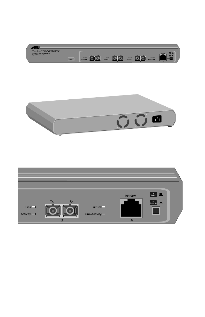
Physical Description
Figure 1 shows the front panel of the switch.
Figure 1
Figure 2 shows the rear view of the switch showing the AC input and fan
locations.
Figure 2
Figure 3 shows the labels for the LEDs indicators for the two types of ports.
The AT-GS903SX Switch (Front)
Rear View of AT-GS903SX Switch
Figure 3
2
LED Indicators Labels (Partial Front Panel)
Page 13

AT-GS903SX Installation Guide
LEDs
Table 1 describes the switch LEDs. Refer to Figure 3 for the labels for the LEDs
for the two types of ports.
AT-GS903SX LED Indicators
Table 1
LED Color Indicates
Power Green On The switch is powered up and ready for use.
Off The switch is powered off.
Gigabit Ethernet Port Stat us LEDs
Link Green On Link is present; port is enabled; full-duplex operation.
Off Link is not present.
Activity Green Flashing Packets are being transmitted/received on this port.
Off No activity on this port.
10/100Mbps Port Status LEDs
Ful/Col Yellow On Full-duplex mode.
Off Half-duplex mode.
Yellow Flashing Two or more d evices attempted to transmit data at the same
time. (Typical under Ethernet CSMA/CD.)
Link/ Yellow On 100M Link is present; port is enabled.
Act Yellow Flashing 100M Packets are being transmitted/received on this port.
Green On 10M Link is present; port is enabled.
Green Flashing 100M Packets are being transmitted/received on this port.
Off Link is not present.
3
Page 14
Product Description
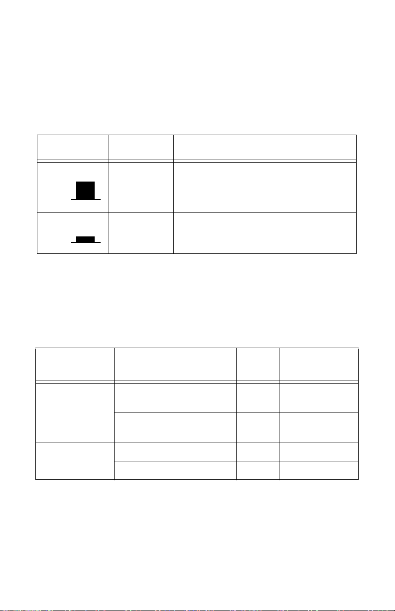
MDI Button
The MDI provides you with the flexibilit y for using a st raight-through cab le to
connect to a hub or another switch, or to any DTE such as an end station or a
server. The button is associated with Port 4. Table 2 describes the MDI button
positions.
MDI Positions
Table 2
Position Label Use
X
To PC
To connect a DTE to the port
Out
=
In
To Hub
To connect a hub or another switch to the port
Media Type
Table 3 describes the standard (connectors), media, and maximum distances
for each port type.
Media Types and Distances
Table 3
Standard Media Type
1000Base-SX (Short
Wave = 850 nm)
100Base-TX Category 5 UTP Cable (100 Mbps) 100 m (328 ft)
50/125um Multimode Fiber
Single-mode: not supported
62.5/125um Multimode Fiber
Single-mode: not supported
MHz/Km
Rating
500 550 m (1804 ft)
160 220 m (722 ft)
Maximum Distance
10Base-T Category 3 UTP Cable (10 Mbps) 100 m (328 ft)
4
Page 15

AT-GS903SX Installation Guide
AC Power Connector
The switch has a single AC power supply socket in the rear panel, which has
autoranging AC voltage inputs. The input voltage range is from
100-120/200-240 VAC, 5 0/60 Hz. The power cord acts as an ON/OFF switch.
Where to Go Next
Proceed to Chapter 2 fo r details on how to install the swi tch .
5
Page 16

Page 17

Chapter 2
Installation
This chapter describes how to install the AT-GS903SX on a desktop, on a wall,
or into a 19-inch rack.
Verifying Switch Package Contents
Make sure the following items are included in your switch package. If any of
the following ite ms are missin g or damaged , contac t your sale s repre sentative.
❑
One AT-GS903SX switch
❑
This Installation Guide
❑
Warranty card
❑
Four rubber feet for desktop installation
❑
Two brackets, eight flathead Phi llips screws, and four larg e screws
and nylon washers for installation into a 19-inch rack
❑
Two screws and plastic anchors for horizontal wall installation
❑
Three spare self-adhesive serial number labels
❑
Power cord (Americas, EC, Australia, and UK only)
Preparing the Site
Use common sense when selecting a location for the switch and observe the
following:
❑
Make sure that the switch’s power is accessible and cables can be
connected easily.
❑
Cabling must be away from sources of electrical noise such as radios,
transmitters, broadband amplifiers, po wer lines, elec tric motors, and
fluorescent fixtu res .
❑
Air flow around the switc h and throug h its v ent s on the s ide a nd rear
must not be restricted.
7
Page 18

Installation
❑
If you are installing the switch on a desk, make sure it is placed on a
level, secure desktop.
❑
Do not place objects on top of the switch.
❑
Do not expose the switch to moisture or water.
❑
Make sure it is in a dust-free environment.
❑
Use dedicated power circuits or power conditioners to supply reliable
electrical power to the network devices.
Note
To install the switch vertically on a wall, use the A T-BRKT18 WallMount Bracket; order it from your Allied Telesyn representative.
Installing the Switch on a Desktop
1. Locate a level, secure surface for the sw itch.
2. Apply the four rubber feet to the bottom of the unit.
3. Put the switch onto the ru b ber fe e t on th e de sk t op.
Warning
The power cord is used as a disconnection device. To de-energize
equipment, disconnect the power cord. ! 8
4. Apply power to the switch by plugging the power cord into the rear of
the unit and plugging the other end into a wall outlet. Verify that the
Power LED lights green.
If the Power LED does not light green, refer to Chapter 3, for f urt her
information.
5. Connect the data cables and observe norm al operatio n as indica ted by
the port LEDs. Refer to Table 1 on page 3 for LED information. For
Port 4, set the MDI Button to the correct setting. Refer to Table 2 on
page 4 for the MDI setting.
8
Page 19

AT-GS903SX Installation Guide
Installing the Switch on a Wall
The switch can be installed vertically or horizont a lly on the wall.
Warning
To install th e switch vertically on a wall, you must us e the acces sory
AT-BRKT18 Wall-Mount Bracket. DO NOT USE the keyholes in the
bottom of the switch chassis to mount it vertically on the wall.
These instructions ar e for mounting the switch hori zo ntally on the wall. To
mount the switch vertically on a wall, follow the instructions supplied with the
AT-BRKT18 Wall-Mount Bracket. Order the bracket from your Allied Telesyn
representative.
1. Select a wall location for the switch.
2. Install two plastic anchors and two pan-head screws into the wall,
separated by 100 mm (approx im at el y 4-i n c hes ) o n center .
3. Positio n the switch onto the wall screws.
Warning
The power cord is used as a disconnection device. To de-energize
equipment, disconnect the power cord. ! 8
4. Apply power to the switch by plugging the power cord into the rear of
the unit and plugging the other end into a wall outlet. Verify that the
Power LED lights green.
If the Power LED does not light green, refer to Chapter 3,
Troubleshooting, for further information.
5. Connect the data cables and observe normal operation as indicated by
the port LEDs. Refer to Table 1 on page 3 for LED information. For
Port 4, set the MDI Button to the correct setting. Refer to Table 2 on
page 4 for the MDI setting.
9
Page 20

Installation
Installing the Switch in a Rack Mount
Caution
Do not use power tools to perform this installation.
1. Remove all cables and the power cord from the switch (if previously
attached).
Caution
Air vents must not be blocked and must have free access to the room
ambient air for cooling. ! 11
2. Attach the rackmounting brackets to each side of the switch as shown
in Figure 4, using the eight flathead screws that came in the switch
package.
Bracket
Figure 4
3. Mount the switch into the rack using four large pan-head screws and
nylon washers (provided).
4. Ensure that there is unrestricted air flow around the swit ch.
Attaching Rackmounting Brackets
Bracket
Warning
The power cord is used as a disconnection device. To de-energize
equipment, disconnect the power cord. ! 8
5. Apply power to the switch by plugging the power cord into the rear of
the unit and plugging the other end into a power outlet.
If the Power LED does not light green, refer to Chapter 3,
Troubleshooting, fo r fu rther information.
10
Page 21

AT-GS903SX Installation Guide
6. Connect the data cables and observe normal operation as indicated by
the port LEDs. Refer to Table 1 on page 3 for LED information. For
Port 4, set the MDI Button to the correct setting. Refer to Table 2 on
page 4 for the MDI setting.
Warranty Registration
When you finish the installation, register your product by completing the
enclosed warranty card and sending it in, or by visiting our web site at
www.alliedtelesyn.com/forms/warranty.htm
registration.
and completing the on-line
11
Page 22

Page 23

Chapter 3
Troubleshooting
This chapter pro vid es i nf orm atio n on how to det e ct and res olve p ro ble ms wi th
your switch. This chapter includes the following sections:
❑
How the Switch Reports Problems
❑
Network Cabling Problems
❑
Common Problems
❑
Calling Technical Support
How the Switch Reports Problems
The LEDs indicate problems with the ports and power. See Table 1 on page 3
for a description of the switch LEDs.
Network Cabling Problems
If you have 100Base-TX (Fast Ethernet), some network problems may be
related to exceeding cabling distances. Refer to the standard IEEE 802.3u,
Clause 29.3.1.2 on
that the collision domain diameter must be within the following limits:
❑
Under 100 m (328 ft) for TX cabling
Worst Case Path Delay Value.
This document specifies
Common Problems
This section lists common possible sources of error and actions required to
correct them.
13
Page 24

Troubleshooting
Link /Activity LED on Any Port is OFF
This can indicate:
❑
A loose data cable.
❑
The device at the other end of the connection is turned OFF.
❑
The data cable is not wired correctly (straight/crossed) for the device.
Perform the fo llo wing st eps i n se qu en ce; yo u need not proceed to the n ext step
if the problem is resolved:
1. Make sure the data cables are secur e.
2. Make sure the device at the end of the connection is turned ON.
3. Make sure the data cable is wired correctly (straight/crossed) for the
device.
4. Contact Allied Telesyn’s Technical Support for help.
Power LED is OFF
If there is no power to the switch, it cannot function.
A Power LED that is OFF can indicate:
❑
A loose power cord.
❑
Power supply failure, malfunction, or loss of power to the power
supply.
❑
A power supply voltage below acceptable levels.
❑
A high switch temperature due to fan failure or extreme ambient
temperature.
Perform the fo llo wing st eps i n se qu en ce; yo u need not proceed to the n ext step
if the problem is resolved:
1. Secure the power cord to the power sour ce and check the Power LED
to see if it is ON.
2. Ensure that the voltage is within the required levels in your region.
3. Contact Allied Telesyn’s Technical Support for help.
14
Page 25

AT-GS903SX Installation Guide
Calling Technical Support
When contacting Alli ed Telesyn for suppo r t o n any of i t s products, provid e
Technical Support with the following information:
❑
Model and serial number
❑
Description of the problem
Refer to page viii or visit our web site at
worldwide locations.
www.alliedtelesyn.com
for a list of
15
Page 26

Page 27

Appendix A
Translated Safety and Emission Information
IMPORTANT
safety statements in this guide.
WICHTIG
enthaltenen Sicherheitshinweise in mehreren Sprachen.
VIGTIGT
sikkerhedsadvarslerne i denne håndbog.
BELANGRIJK
veiligheidsopmerkingen in deze gids.
IMPORTANT
instructions de sécurité figurant dans ce guide.
TÄRKEÄÄ
kielellä.
IMPORTANTE
avvisi di sicurezza di questa guida.
VIKTIG
sikkerhetsinformasjonen i denne veiledningen.
IMPORTANTE
advertências de segurança neste guia.
IMPORTANTE
los mensajes de seguridad incluidos en esta guía.
: This appendix conta ins multip le-languag e translations for the
: Dieser Anhang enthält Über se tzungen der in diesem Handbuch
: Dette tillæg indehol der oversættelser i flere sprog af
: Deze appendix bevat vertalingen in meerdere talen van de
: Cette annexe contient la traduction en plusieurs langues des
: Tämä liite sisältää tässä oppaassa esiintyvät turvaohjeet usealla
: questa appendice contiene traduzioni in più lingue degli
: Dette tillegget inneholder oversettelser til flere språk av
: Este anexo contém traduções em vários idiomas das
: Este apéndice con tiene traduccion es en mú ltiples idio mas de
OBS!
Denna bilaga innehåller flerspråkiga översättningar av
säkerhetsmeddelandena i de nna handledn ing.
17
Page 28

Translated Safety and Emission Information
Standards: This produ c t meets the following sta nda rd s.
U.S. Federal Communications Commission
RADIATED ENERGY
Note: This equipment has been tested and found to comply with the
limits for a Class A digital device pursuant to Part 15 of the FCC Rules.
These limits are designed to provide reasonable protection against
harmful interference when the equipment is operated in a commercial
environment. This equipment generates, uses, and can radiate radio
frequency ene rg y and, if not installed and used in accord ance with this
instruction manual, may cause harmful interference to radio
communications. Operation of this equipment in a residential area is
likely to cause harmful interfer ence in which case the user will be
required to correct the interference at his own expense.
Note: Modifications or changes not expressly approved by the
manufacturer or the FCC can void your right to operate this equipment.
Canadian Department of Communications
This Class A digital apparatus meets all requirements of the Canadian
Interference-Cau sin g E qui pmen t Regulations.
Cet appareil numérique de la classe A respecte toutes les exigences du
Règlement sur le matériel brouilleur du Canada.
1 RFI Emission EN55022 Class A
!
2 WARNING: In a domestic environment this product may cause radio
!
3 Immunity EN50082-1
!
4 Electrical Safety EN60950, UL1950, CSA 950
!
5 This is a “CLASS 1 LED PRODUCT”.
!
6 ELECTRICAL NOTICES
!
7 LIGHTNING D A NG ER
!
8CAUTION: POWER CORD IS USED AS A DISCONNECTION DEVICE.
!
18
interference in which case the user may be required to take adequate
measures.
SAFETY
WARNING: ELECTRIC SHOCK HAZARD
To prevent ELECTRIC shock , do not remove the cover. No user-serviceable
parts inside. This unit contains HAZARDOUS VOLTAGES and should only
be opened by a trained and qualified technician. To avoid the possibility of
ELECTRIC SHOCK, disconnect electric power to the prod uct before
connecting or disconnecting the LAN cables.
DANGER: DO NOT WORK on equipment or CABLES during periods of
LIGHTNING ACTIVITY.
TO DE-ENERGIZE EQUIPMENT, disconnect the power cord.
Page 29

AT-GS903SX Installation Guide
9 ELECTRICAL - TYPE CLASS 1 EQUI PMENT
!
THIS EQUIPMENT MUST BE EARTHED. Power plug must be connected
to a properly wired earth ground socket outlet. An improperly wired socket
outlet could place hazardous voltages on accessible metal parts.
10 PLUGGABLE EQUIPMENT, the socket outlet shall be installed near the
!
equipment and shall be easily accessible.
11 CAUTION: Air vents must not be blocked and must have free access to the
!
12 OPERATING TEMPERATURE: This product is designed for a maximum
!
13 ALL COUNTRIES: Install product in accordance with local and National
!
1 Hochfrequenzstörung EN55022 Klasse A
!
2 WARNUNG: Bei Verwendung zu Hause kann dieses Produ kt
!
3 Störsicherheit EN50082-1
!
4 Elektrische Sicherheit EN60950, UL1950, CSA 950
!
5 Das ist ein "LED Produkt der Klasse 1"
!
6ACHTUNG: GEFÄHRLICHE SPANNUNG
!
7 GEFAHR DURCH BLITZSCHLAG
!
!
8
9 GERÄTE DER KLASSE 1
!
10 STECKBARES GERÄT: Die Anschlu ßbuchse sollte in der Nähe der
!
room ambient air for cooling.
ambient temperature of 40° degrees C.
Electrical Codes.
Normen: Dieses Produkt erfüllt die Anforderungen der nachfolgenden
Normen.
Funkstörungen hervorruf en . In dies e m Fal l müßte der Anw ender
angemessene Gegenmaßnahmen ergreifen.
SICHERHEIT
Das Gehäuse nicht öffnen. Das Gerät enthält keine vom Benutzer
wartbaren Teile. Das Gerät steht unter Hochspannung und darf nur von
qualifiziertem technischem Personal geöffnet werden. Vor Anschluß der
LAN-Kabel, Gerät vom Netz trennen.
GEFAHR: Keine Arbeiten am Gerät oder an den Kabeln während eines
Gewitters ausführen.
VORSICHT: DAS NETZKABEL DIENT ZU M TRENNEN DER
STROMVERSORG UNG. ZU R TRENN UNG VO M NETZ, K ABEL AUS
DER STECKDOSE ZIEHEN.
DIESE GERÄTE MÜSSEN GEERDET SEIN. Der Netzstecker darf nur mit
einer vorschriftsmäßig geerdeten Steckdose verbunden werden. Ein
unvorschriftsmäßiger Anschluß kann die Metallteile des Gehauses unter
gefährliche elektrische Spannungen setzen.
Einrichtung angebracht werden und leicht zugänglich sein."
19
Page 30

Translated Safety and Emission Information
11 VORSICHT
!
12 BETRIEBSTEMPERATUR: Dieses Produkt wurde für den Betrieb in
!
13 ALLE LÄNDER: Installation muß örtlichen und nationalen elektrischen
!
1 Radiofrekvens forstyrrelses emissionEN55022 Klasse A
!
2ADVARSEL: I et hjemligt milj ø kunne dette produkt forårsage radio
!
3 Immunitet EN50082-1
!
4 Elektrisk sikkerhed EN60950, UL1950, CSA 950
!
5 Dette er et "Produkt unde r Klass e 1 LED
!
6 ELEKTRISKE FORHOLDSREGLER
!
7 FARE UNDER UVEJR
!
8ADVARSEL: DEN STRØMFØRENDE LEDNING BRUGES TIL AT
!
9 ELEKTRISK - KLASSE 1-UDSTYR
!
10 UDSTYR TIL STIKKO NTAKT, stikkontakten bør installeres nær ved
!
11 ADVARSEL: Ventilationsåbninger må ikke blokeres og skal have fri
!
Die Entlüftungsöffnunge n dü rfe n nicht versperrt s e in un d müssen zum
Kühlen freien Zugang zur Raumluft haben.
einer Umgebungstemperatur v on n ich t m ehr al s 40 ° C entwor fen.
Vorschriften entsprechen.
Standarder: Dette produkt tilfredsstiller de følgende standarder.
forstyrrelse. Bliver det tilfældet, påkræves brugeren muligvis at tage
tilstrækkelige foranstaltninger.
SIKKERHED
ADVARSEL: RISIKO FOR ELEKTRISK STØD
For at forebygge ELEKTRISK stød, undlad at åbne apparatet. Der er ingen
indre dele, der kan repareres af brugeren. Denne enhed indeholder
LIVSFARLIGE STRØMSPÆNDINGER og b ør kun åbnes af en uddannet
og kvalificeret tekniker. For at undgå risiko for ELEKTRISK STØD,
afbrydes den elektriske strøm til produktet, før LAN-kablerne monteres
eller afmonteres.
FARE: UNDLAD at arbejde på udstyr eller K ABLER i perioder me
LYNAKTIVITET.
AFBRYDE STRØMMEN. SKA L STRØMMEN TIL APP ARATET
AFBRYDES, tages ledningen ud af stikket.
DETTE UDSTYR KRÆVER JORDFORBINDELSE. Stikket skal være
forbundet med en korrekt installeret jordforbunden stikkontakt. En
ukorrekt installeret stikkontakt kan s æ tte l iv sfarlig spænding til
tilgængelige metaldele.
udstyret og skal være le ttilg ængelig.
adgang til den omgivende luft i rummet for afkøling.
20
Page 31

AT-GS903SX Installation Guide
12 BETJENINGSTEMPERATUR: Dette apparat er konstrueret til en
!
omgivende temperatur på maksimum 40 grader C.
13 ALLE LANDE: Installation af produktet skal ske i overensstemmelse med
!
1 RFI Emissie EN55022 Klasse A
!
2WAARSCHUWING: Binne n shuis ka n dit produ ct radiosto ri ng
!
3 Immuniteit EN50082-1
!
4 Electrische Veilighei EN60950, UL1950, CSA 950
!
5 Dit is een "KLASSE 1 LED-PR OD UKT ".
!
6 WAARSCHUWINGEN MET BETREKKING TOT ELEKTRICITEIT
!
7 GEVAAR VOOR BLIKSEMINSLA
!
8 WAARSCHUWING: HET TOESTEL WORDT UITGESCHAKELD DOOR
!
9 ELEKTRISCHE TOESTELLEN VAN KLASSE 1
!
10 AAN TE SLUITEN APPARATUUR, de contactdoos wordt in de nabijhei
!
11 OPGELET: De ventilatiegaten mogen niet worden gesperd en moeten de
!
12 BEDRIJFSTEMPERATUUR: De omgevingstemperatuur voor dit
!
13 ALLE LANDEN: het toestel installeren overeenkomstig de lokale en
!
lokal og nationa l lovgivning for elektriske installationer.
Eisen: Dit product voldoet aan de volgende eisen.
veroorzaken, in welk geval de gebr u ike r verp lic ht kan worden om gepaste
maatregelen te nemen.
VEILIGHEID
WAARSCHUWING: GEVAAR VOOR ELEKTRISCHE SCHOKKE
Verwijder het deksel niet, teneinde ELEKTRISCHE schokken te
voorkomen. Binnenin bevinden zich gee n onder de len die door de gebr u ike r
onderhouden kunnen worden. Dit toestel staat onder GEV AARLIJKE
SPANNING en mag alleen worden geopend door een daartoe opgeleide en
bevoegde technicus. Om het gevaar op ELEKTRISCHE SCHOKKEN te
vermijden, moet u het toestel van de stroombron ontkoppelen alvorens de
LAN-kabels te koppelen of ontkoppelen.
GEVAAR: NIET aan toestellen of KABELS WERKEN bij BLIKSEM.
DE STROOMKABEL TE ONTKOPPELEN.OM HET TOESTEL
STROOMLOOS TE MAKEN: de stroomkabel ontkopp elen.
DIT TOESTEL MOET GEAARD WORDEN. De stekker moet aangesloten
zijn op een juist geaarde contactdoos. Een onjuist geaarde contactdoos kan
de metalen onderdelen waarmee de gebruiker eventueel in aanraking komt
onder gevaarlijke spann ing stellen.
van de apparatuur geïnstalleerd en is gemakkelijk te bereiken."
omgevingslucht ongehind erd toelaten v oor afkoeling .
produkt mag niet meer bedragen dan 40 gr aden Celsius.
nationale elektrische voorschriften.
21
Page 32

Translated Safety and Emission Information
Normes: ce produit est conforme aux normes de suivantes:
1 Emission d’interférences radioélectriques EN55022 Classe A
!
2MISE EN GARDE : dans un environnement domestique, ce produit peut
!
3 Immunité EN50082 - 1
!
4 Sécurité électrique EN60950, UL1950, CSA 950
!
5 Ce matériel est un "PRODUIT À DIODE ÉLECTROLUMINESCENTE
!
6 INFORMATION SUR LES RISQUES ÉLECTRIQUES
!
7 DANGER DE FOUDRE
!
8 ATTENTION: LE CO RDON D’ALIMENTATION SERT DE MISE HORS
!
9 ÉQUIPEMENT DE CLASSE 1 ÉLECTRIQUE
!
10 EQUIPEMENT POUR BRANCHEMENT ELECTRIQUE, la prise de sortie
!
11 ATTENTION: Ne pas bloquer les fentes d’aération, ceci empêcherait l’air
!
12 TEMPÉRATURE DE FONCTIONNEMENT: Ce matériel est capable de
!
13 POUR TOUS PAYS: Installer le matériel conformément aux normes
!
provoquer des interférences radioélectriques. Auquel cas, l’utilisateur devra
prendre les mesures adéqu ates.
SÉCURITÉ
DE CLASSE 1”.
AVERTISSEMENT: DANGER D’ÉLECTROCUTION
Pour éviter toute ÉLECTROCUTION, ne pas ôter le revêtement protecteur
du matériel. Ce matériel ne contient aucun é lémen t rép arable p ar
l’utilisateur. Il comprend des TENSIONS DANGEREUSES et ne doit être
ouvert que par un technicien dûment qualifié. Pour éviter tout risque
d’ÉLECTROCUTION, débrancher le matériel avant de connecter ou de
déconnecter les câbles LAN.
DANGER: NE PAS MANIER le matériel ou les CÂBLES lors d’activité
orageuse.
CIRCUIT. POUR COUPER L’ALIMENTATION DU MATÉRIEL,
débrancher le cordon.
CE MATÉRIEL DOIT ÊTRE MIS A LA TERRE. La prise de courant doit
être branchée dan s une prise femelle correctement mise à la terre car des
tensions dangereuses risqueraient d’atteindre les pièces métalliques
accessibles à l’utilisateur.
doit être placée près de l’équipement et facilement accessible".
ambiant de circuler librement pour le refroidissement.
tolérer une température ambiante maximum de ou 40 degrés Celsius.
électriques nationales et locales.
22
Page 33

AT-GS903SX Installation Guide
Standardit: T ämä tuote on seuraavien s tandardien mukainen.
1 Radioaaltojen häirintä EN55022 Luokka A
!
2 VAROITUS: Kotiolosuhteissa tämä laite voi aiheuttaa radioaaltojen
!
3 Kestävyys EN50082-1
!
4 Sähköturvallisuus EN60950, UL1950, CSA 950
!
5 Tämä on "ENSIMMÄISEN LUOKAN VALODIODITUOTE".
!
6 SÄHKÖÖN LIITTYVIÄ HUOMAUTUKSIA
!
7 SALAMANISKUVAARA
!
8 HUOMAUTUS: VIRTAJOHTOA KÄYTETÄÄN
!
9 SÄHKÖ - TYYPPILUOK AN 1 LAITTEET
!
10 PISTORASIAAN KYTKETTÄVÄ LAITE; pistorasia on asennettava
!
11 HUOMAUTUS: Ilmavaihtoreikiä ei pidä tukkia ja niillä täytyy olla vapaa
!
12 KÄYTTÖLÄMPÖTILA: Tämä tuote on suunniteltu ympäröivän ilman
!
13 KAIKKI MAAT: Asenna tuote paikallisten ja kansallisten
!
häiröitä, missä tapauksessa laitteen käyttäjän on mahdollisesti ryhdyttävä
tarpeellisiin toimenpiteisiin.
TURVALLISUUS
VAROITUS: SÄHKÖISKUVAARA
Estääksesi SÄHKÖISKUN älä poista kantta. Sisällä ei ol e käyttäjän
huollettavissa olevia osia. Tämä laite sisältää VAARALLISIA
JÄNNITTEITÄ ja sen voi av ata vain koulutettu ja pätevä teknikko.
Välttääksesi SÄHKÖISKUN mahdollisuuden katkaise sähkövirta
tuotteeseen ennen kuin liität tai irrotat paikallisverkon (LAN) kaapelit.
HENGENVAARA: ÄLÄ TYÖSKENTELE laitteiden tai KAAPELEIDEN
KANSSA SALAMOINNIN AIKANA.
VIRRANKATKAISULA IT TEENA. VIRTA KATKAISTAAN irrottamalla
virtajohto.
TÄMÄ LAITE TÄYTYY MAADOITTAA. Pistoke täytyy liittää kunnollisesti
maadoitettuun pistorasiaan. Virheellisesti johdotettu pistorasia voi altistaa
metalliosat vaarallisille jännitteille.
laitteen lähelle ja siihen on oltava esteetön pääsy."
yhteys ympäröivään huoneilmaa n, jotta ilmanvaihto tapahtuisi.
maksimilämpötilalle 40°C.
sähköturvallisuusmääräysten mukaisesti.
23
Page 34

Translated Safety and Emission Information
Standard: Questo prodotto è conforme ai seguenti standard.
1 Emissione RFI (interferenza di radiofrequenza) EN55022 Classe A
!
2 AVVERTENZA: in ambiente domestico questo prodotto potrebbe causare
!
3 Immunità EN50082-1
!
4 Sicurezza elettrica EN60950, UL1950, CSA 950
!
5 Questo è un "PRODOTTO CON LED DI CLASSE 1".
!
6 AVVERTENZE ELETTRICHE
!
7 PERICOLO DI FULMINI
!
8ATTENZIONE: IL CAVO DI ALIMENTAZIONE È USATO COME
!
9 ELETTRICITÀ - DISPOSITIVI DI CLASSE 1
!
10 APPARECCHIATUR A COLLEGABILE, la pre s a va insta l lata vicino
!
11 ATTENZIONE: le prese d’aria non vanno ostruite e devono consentire il
!
12 TEMPERATURA DI FUNZIONAMENTO: Questo prodotto è concepito
!
13 TUTTI I PAESI: installare il prodotto in conformità delle vigenti
!
radio interferenza. In questo caso potrebbe richiedersi al l’ utente di
prendere gli adeguati provvedimenti.
NORME DI SICUREZZA
ATTENZIONE: PERICOLO DI SCOSSE ELETTRICHE
Per evitare SCOSSE ELETTRICHE non asportare il coperchio. Le
componenti interne non sono riparabili dall’utente. Questa unità ha
TENSIONI PERICOLOSE e va aperta solamente da un tecnico
specializzato e qualificato. Per evitare ogni possibilità di SCOSSE
ELETTRICHE, interrompere l’alimentazione del dispositivo prima di
collegare o staccare i cavi LAN.
PERICOLO: NON LAVO RARE sul dispositivo o sui C A VI durante
PRECIPITAZIONI TEMPORALESCHE.
DISPOSITIVO DI DISATTIVAZIONE. PER TOGLIERE LA CORRENTE
AL DISPOSITIVO staccare il cavo di alimentazione.
QUESTO DISPOS ITIVO DEVE AVERE LA M ESSA A TERRA. La spina
deve essere inserita in una presa di corrente specificamente dotata di messa
a terra. Una presa non cablata in maniera corretta rischia di scar icare una
tensione pericolosa su parti metall ic he ac cessibili.
all’apparecchio per risultare facilmente accessibile".
libero ricircolo dell’aria ambiente per il raffreddamento.
per una temperatura ambientale massima di 40 gradi centigradi.
normative elettriche nazionali.
24
Page 35

AT-GS903SX Installation Guide
Sikkerhetsnormer: Dette produktet tilfredsstiller følgende
sikkerhetsnormer.
1 RFI stråling EN55022 Klasse A
!
2ADVARSEL: Hvis dette produktet benyttes til privat bruk, kan produktet
!
3 Immunitet EN50082-1
!
4 Elektrisk sikkerhet EN60950, UL1950, CSA 950
!
5 Dette er et "KLASSE 1 LED PRODUKT".
!
6 ELEKTRISITET
!
7 FARE FOR LYNNEDSLAG
!
8FORSIKTIG: STRØMLEDNINGEN BRUKES TIL Å FRAKOBLE
!
9 ELEKTRISK - TYPE 1- KLASSE UTSTYR
!
10 UTSTYR FO R S TIKKONTAKT. Stikkontakten skal monteres i nærheten
!
11 FORSIKTIG: Lufteventilene må ikke blokkeres, og må ha fri tilgang til
!
12 DRIFTSTEMPERATUR: D e tte produktet er konstruert for bruk i
!
13 ALLE LAND: Produktet må installeres i sa msvar med de lokale og
!
forårsake radioforstyrrelse. Hvis dette skjer, må brukeren ta de nødvendige
forholdsregler.
SIKKERHET
ADVARSEL: FARE FOR ELEKTRISK SJOKK
For å unngå ELEKTRISK sjokk, må dekslet ikke tas av. Det finnes ingen
deler som brukeren kan reparere på innsiden. Denne enheten inneholder
FARLIGE SPENNING ER, og må kun åpnes av en faglig kvalifisert
tekniker. For å unngå ELEKTRISK SJOKK må den elektriske strømmen til
produktet være avslått før LAN-kablene til- eller frakobles.
FARE: ARBEID IKKE på utstyr eller KA BLER i TORDENVÆR.
UTSTYRET. FOR Å DEAKTIVISERE UTSTYRET, må strømforsyningen
kobles fra.
DETTE UTSTYRET MÅ JORDES. Strømkontakten må være tilkoplet en
korrekt jordet kontakt. En kontakt som ikke er korrekt jordet kan føre til
farlig spenninger i lett t ilgjengelige metalldeler.
av utstyret og skal være lett tilgjengelig."
luft med romtemperatur for avkjøling.
maksimum romtemperatur på 40 grader celsius.
nasjonale elektriske koder.
25
Page 36

Translated Safety and Emission Information
Padrões: Este produto atende aos seguintes padrões.
1 Emissão de interferência de radiofrequênciaEN 55022 Classe A
!
2AVISO: Num ambiente doméstico este pro d uto pode causar interferência
!
3 Imunidade EN50082-1
!
4 Segurança Eléctrica EN60950, UL1950, CSA 950
!
5 Este é um "PRODUTO CLASSE 1 LED".
!
6 AVISOS SOBRE CARACTERÍSTICAS ELÉTRICAS
!
7 PERIGO DE CHOQUE CAUSADO POR RAI
!
8 CUIDADO: O CABO DE ALIMENTAÇÃO É UTILIZADO COMO UM
!
9 ELÉTRICO - EQUIPAMENTOS DO TIPO CLASSE 1
!
10 EQUIPAMENTO DE LIGAÇÃO, a tomada eléctrica deve estar instalada
!
11 CUIDADO: As aberturas de ventilação não devem ser bloqueadas e devem
!
12 TEMPERATURA DE FUNCIONAMENTO: Este produto foi projetado
!
13 TODOS OS PAÍSES: Instale o produto de acordo com as normas nacionais
!
na radiorrecepção e, ne ste caso, pode ser necessário que o utente tome as
medidas adequadas.
SEGURANÇA
ATENÇÃO: PERIGO DE CHOQUE ELÉTRICO
Para evitar CHOQUE ELÉTRICO, não retire a tampa. Não contém peças
que possam ser consertadas pelo usuário. Este aparelho contém
VOLTAGENS PERIGOSAS e só dev e ser aberto por um técnico qualificado
e treinado. Para evitar a possibilidade de CHOQUE ELÉTRICO,
desconecte o aparelho da fonte de energia elétrica antes de conectar e
desconectar os cabos da LAN.
PERIGO: NÃO TRA BALHE no equipamento ou nos CABOS durante
períodos suscetíveis a QUEDAS DE RAIO.
DISPOSITIVO DE DESCONEXÃO. PARA DESELETRIFICAR O
EQUIPAMENTO, desconecte o cabo de ALIMEN TAÇÃO.
DEVE SER FEITA LIGAÇÃO DE FIO T ERRA PARA EST
EQUIPAMENTO. O plugue de alimentação deve ser conectado a uma
tomada com adequada ligação de fio terra. Tomadas sem adequada ligação
de fio terra podem transmitir voltagens perigosas a peças metálicas
expostas.
perto do equipamento e ser de fácil acesso."
ter acesso livre ao ar ambiente para arrefecimento adequado do aparelho.
para uma temperatura ambiente máxima de 40 graus centígrados.
e locais para instalações elétricas.
26
Page 37

AT-GS903SX Installation Guide
Estándares: Este producto cumple con los siguientes estándares.
1 Emisión RFI EN55022 Clase A
!
2ADVERTENCIA: en un entorno doméstico, este producto puede causar
!
3 Inmunidad EN50082-1
!
4 Seguridad eléctrica EN60950, UL1950, CSA 950
!
5 Este es un "PRODUCTO DE DIODO LUMINISCENTE (LED) CLASE
!
6 AVISOS ELECTR I COS
!
7 PELIGRO DE RAYOS
!
8 ATENCION: EL CABLE DE ALIMENTACION SE USA COMO UN
!
9 ELECTRICO - EQUIPO DE L TIPO CLASE 1
!
10 EQUIPO CONECTABLE, el tomacorriente se debe instalar cerca del
!
11 ATENCION: Las aberturas para ventilación no deberán bloquearse y
!
12 TEMPERATURA RE QUERIDA PAR A LA OPERAC IÓN: Este producto
!
13 PARA TODOS LOS PAÍSES: Monte el producto de acuerdo con los
!
radiointerferencias, en cuyo caso, puede requerirse del usuario que tome las
medidas que sean convenientes al respec to.
SEGURIDAD
1"
ADVERTENCIA: PELIGRO DE ELECTROCHOQUE
Para evitar un ELECTROCHOQUE, no quite la tapa. N o hay ningún
componente en el int erior al cual puede prestar servicio el usuario. Esta
unidad contiene VOLTAJES PELIGROSOS y sólo deberá abrirla un técnico
entrenado y calificado. Para evitar la posibilidad de ELECTROCHOQUE
desconecte la corriente eléctrica que llega al producto antes de conectar o
desconectar los cables LAN.
PELIGRO: NO REALICE NINGUN TIPO DE TRABAJO O CONEXIO
en los equipos o en LOS CABLES durante TORMENTAS ELECTRICAS.
DISPOSITIVO DE DESCONEXION. PARA DESACTIVAR EL EQUIPO,
desconecte el cable de alimentación.
ESTE EQUIPO TIENE QUE TENER CONEXION A TIERRA. El cable
tiene que conectarse a un enchufe a tierra debidamente instalado. Un
enchufe que no está correctamente instalado podría ocasionar tensiones
peligrosas en las partes metálic as que están expuestas.
equipo, en un lugar con acceso fácil".
deberán tener acceso libre al aire ambiental de la sala para su enfriamiento.
está diseñado para una temper atura ambiental máxima de 40 grados C.
Códigos Eléctricos locales y nacionales.
27
Page 38

Translated Safety and Emission Information
Standarder: De nna produkt uppfyller följa n de standarder.
1 Radiostörning EN55022 Klass A
!
2 VARNING: Denna produkt kan ge upphov till radiostörningar i hemmet,
!
3 Immunitet EN50082-1
!
4 Elsäkerhet EN60950, UL1950, CSA 950
!
5 Detta är en "KLASS 1 LYSDIODPRODUKT".
!
6 TILLKÄNNAGIVANDEN BETRÄFFANDE ELEKTRICITETSRISK:
!
7 FARA FÖR BLIXTNEDSLAG
!
8 VARNING: NÄTKABELN ANVÄNDS SOM STRÖMBRYTARE FÖR ATT
!
9 ELEKTRISKT - TYP KLASS 1 UTRUSTNING
!
10 UTRUSTNING MED PLUGG. Uttaget skall installeras i utrustningens
!
11 VARNING: Luftventilerna får ej blockeras och måste ha fri tillgång till
!
12 DRIFTSTEMPERATUR: Denna produkt är konstruerad för
!
13 ALLA LÄNDER: Installera produkten i enlighet med lokala och statliga
!
vilket kan tvinga användaren till att vi dtaga erforderliga åtgärder.
SÄKERHET
RISK FÖR ELEKTRISK STÖTFör att undvika ELEKTRISK stöt, ta ej av
locket. Det finns inga delar inuti som behöver underhållas. Denna apparat
är under HÖGSPÄNNING och får endast öppnas av en utbilda
kvalificerad tekniker. För att undvika ELEKTRISK STÖT, koppla ifrån
produktens strömanslutning in na n L AN-k a blarna ansl ut s eller kopplas ur.
FARA: ARBETA EJ på utrustningen eller kablarna vid ÅSKVÄDER.
KOPPLA FRÅN STRÖMMEN, dra ur nätkabeln.
DENNA UTRUSTNING MÅSTE VARA JORDAD. Nätkabeln måste vara
ansluten till ett ordentligt jord at uttag. Ett felaktigt uttag kan göra att
närliggande metalldelar utsätts för högspänning. Apparaten skall anslutas
till jordat uttag, när den ansluts till ett nätverk.
närhet och vara lättåtkomligt".
omgivande rumsluft för avsvalning.
rumstemperatur ej överstigande 40 grader Celsius.
bestämmelser för elektrisk utrustning.
28
Page 39

Appendix B
Technical Specifications
Physical Sp ecifications
Dimensions (W x D x H): 341 mm x 231 mm x 43 mm
(13.3 in x 9 in x 1.69 in)
Weight: 2.3 kg (5.1 lb)
Environmental Specifications
Operating Temperature: 0° C to 40° C (32° to 104° F)
Storage Temperature: -20° C to 60° C (-4° to 140° F)
Operating Humidity: 10% to 90% non-condens ing
Non-operating Humidity: 10% to 95% non-condensing
Power Specifications
Maximum Power
Consumption: 23 W
AC Input Voltage: 100-120/200-240VAC, 50/60Hz
Agency Compliance
Standard: IEEE 802.3u, IEEE 802.3ab, IEEE 802.3z
EMI/RFI: Meets FCC Class A, EN55022 Class A
Safety: Conforms to UL 1950, CSA C22.2 No. 950,
TUV EN 60950
Immunity: Conforms to EN50082-1
CE Compliant
29
Page 40

Page 41

Appendix C
Technical Support Fax Order
Name_________________________________________________________________
Company_____________________________________________________________
Address ______________________________________________________________
City ___________________ State/Province_______________________________
Zip/Postal Code ______________Country _______________ ________________
Phone_____________________________Fax _______________________________
Incident Summary
Model number of Allied Telesyn product I am using __________________
Firmware release number of Allied Telesyn product _________________
Other network software products I am using (e.g., network managers)
______________________________________________________________________
______________________________________________________________________
______________________________________________________________________
Brief summary of problem ___________________________________________
______________________________________________________________________
______________________________________________________________________
Conditions (List the steps that led up to the problem.)________________
______________________________________________________________________
______________________________________________________________________
______________________________________________________________________
______________________________________________________________________
______________________________________________________________________
Detailed description (Please use separate sheet)
Please also fax printouts of relevant files such as batch files and
configuration files. When completed, fax this s heet to the approp riate
Allied Telesyn office. Fax numbers can be found on page viii.
31
Page 42

Page 43

Appendix D
AT-GS903SX Installation Guide Feedback
Please tell us what additional information you would like to see
discussed in this guide. If there are topics you would like information
on that were not covered in this guide, please photocopy this page,
answer the questions and fax or mail this form back to Allied Telesyn.
The mailing address and fax number are at the bottom of the page.
Your comments are valuable when we plan future revisions of this
guide.
I found the following the most valuable _______________ ____________
_______________________________________________________________
_______________________________________________________________
_______________________________________________________________
_______________________________________________________________
I would like the following more developed ________________________
_______________________________________________________________
_______________________________________________________________
_______________________________________________________________
_______________________________________________________________
I would find this guide more useful if _____________________________
_______________________________________________________________
_______________________________________________________________
_______________________________________________________________
Please fax or mail your fee d back. Fax to 1-408-736-0100. Or mail to:
Allied Tele s yn In t ern ational, Corp .
c/o Technical Communications
960 Stewart Drive, Suite B
Sunnyvale, CA 94086 USA
PN 613-10842-00 Rev C
33
Page 44

 Loading...