

Page 1

AT-GS2002/SP
Gigabit Ethernet to Fiber SFP Media Converter
AT-GS2002/SP Media Converter
PN 613-001759 Rev. A
Installation Guide
Page 2

Copyright © 2012 Allied Telesis, Inc.
All rights reserved. No part of this publication may be reproduced without prior written permission from Allied Telesis,
Inc.
Allied Telesis and the Allied Telesis logo are trademarks of Allied Telesis, Incorporated. All other product names,
company names, logos or other designations mentioned herein are trademarks or registered trademarks of their respective
owners.
Allied Telesis, Inc. reserves the right to make changes in specifications and other information contained in this document
without prior written notice. The information provided herein is subject to change without notice. In no event shall Allied
Telesis, Inc. be liable for any incidental, special, indirect, or consequential damages whatsoever, including but not limited
to lost profits, arising out of or related to this manual or the information contained herein, even if Allied Telesis, Inc. has
been advised of, known, or should have known, the possibility of such damages.
Page 3

Electrical Safety and Emissions Standards
This product meets the following standards.
U.S. Federal Communications Commission
Declaration of Conformity
Manufacturer Name: Allied Telesis, Inc.
Declares that the product: Fast Ethernet Switch
Model Numbers: AT-GS2002/SP
This product complies with FCC Part 15B, Class B Limits:
This device complies with part 15 of the FCC Rules. Operation is subject to the following two conditions: (1) This device
must not cause harmful interference, and (2) this device must accept any interference received, including interference
that may cause undesired operation.
Radiated Energy
Note: This equipment has been tested and found to comply with the limits for a Class B digital device pursuant to Part 15
of FCC Rules. These limits are designed to provide reasonable protection against harmful interference in a residential
installation. This equipment generates, uses and can radiate radio frequency energy and, if not installed and used in
accordance with instructions, may cause harmful interference to radio or television reception, which can be determined
by turning the equipment off and on. The user is encouraged to try to correct the interference by one or more of the
following measures:
- Reorient or relocate the receiving antenna.
- Increase the separation between the equipment and the receiver.
- Connect the equipment into an outlet on a circuit different from that to which the receiver is connected.
- Consult the dealer or an experienced radio/TV technician for help.
Changes and modifications not expressly approved by the manufacturer or registrant of this equipment can void your
authority to operate this equipment under Federal Communications Commission rules.
Industry Canada
This Class B digital apparatus meets all requirements of the Canadian Interference-Causing Equipment Regulations.
Cet appareil numérique de la classe B respecte toutes les exigences du Règlement sur le matériel brouilleur du Canada.
RFI Emissions FCC Class B, CISPR 22 Class B, EN55022 Class B,
EN55022 Class B, VCCI Class B, C-TICK
Immunity EN55024
Electrical Safety CSA22.2 No.950, TUV (EN60950), CE UL1950
3
Page 4

Electrical Safety and Emissions Standards
Translated Safety Statements
Important: The indicates that a translation of the safety statement is available on the Allied
Telesis website at www.alliedtelesis.com.
4
Page 5

Contents
Electrical Safety and Emissions Standards ......................................................................................................................3
Preface ................................................................................................................................................................................11
Symbol Conventions .....................................................................................................................................................12
Contacting Allied Telesis ...............................................................................................................................................13
Chapter 1: Overview ..........................................................................................................................................................15
Introduction....................................................................................................................................................................16
General ..................................................................................................................................................................16
Twisted-Pair Port....................................................................................................................................................16
SFP Port.................................................................................................................................................................17
LEDs ......................................................................................................................................................................17
Installation Options.................................................................................................................................................17
MAC Address Table ...............................................................................................................................................17
Dimensions ............................................................................................................................................................18
Environmental Operating Conditions .....................................................................................................................18
Front and Back Panels ..................................................................................................................................................19
Twisted-Pair Ports .........................................................................................................................................................20
Cable Specifications...............................................................................................................................................20
MDI/MDI-X Mode ...................................................................................................................................................20
Auto-Negotiation Mode ..........................................................................................................................................21
Flow Control and Back Pressure............................................................................................................................21
SFP Port........................................................................................................................................................................22
LEDs..............................................................................................................................................................................23
Power LED .............................................................................................................................................................23
MODE LEDs...........................................................................................................................................................24
Twisted-Pair Port LEDs..........................................................................................................................................25
Fiber Optic Port LEDs (SFP Slot)...........................................................................................................................26
DIP Switches..........................................................................................................................................................26
Power Supply ................................................................................................................................................................27
Chapter 2: Installation .......................................................................................................................................................29
Safety Precaution Review .............................................................................................................................................30
Site Selection ................................................................................................................................................................32
Unpacking the AT-GS2002/SP Media Converter ..........................................................................................................33
Rear Panel DIP Switches Configuration........................................................................................................................34
SFP Transceiver Installation .........................................................................................................................................35
Desktop Installation .......................................................................................................................................................37
Wall Mount Installation ..................................................................................................................................................38
Rack Mount Installation .................................................................................................................................................39
Cable Installation...........................................................................................................................................................40
Connecting to the Copper Port...............................................................................................................................40
Connecting to the SFP Module ..............................................................................................................................41
Powering On the AT-GS2002/SP Media Converter ......................................................................................................43
Chapter 3: Troubleshooting ..............................................................................................................................................45
Power LED is Off...........................................................................................................................................................46
Twisted-Pair Port LINK/ACT LED is Off ........................................................................................................................47
SFP Port LINK/ACT LED Off.........................................................................................................................................48
Appendix A: Technical Specifications .............................................................................................................................49
5
Page 6

Contents
Physical Specifications ..................................................................................................................................................49
Environmental Specifications.........................................................................................................................................49
Power Specifications .....................................................................................................................................................49
Safety and Electromagnetic Emissions Certifications....................................................................................................50
Connectors and Port Pinouts.........................................................................................................................................50
6
Page 7

Figures
Figure 1. AT-GS2002/SP Front Panel .................................................................................................................................19
Figure 2. AT-GS2002/SP Back Panel..................................................................................................................................19
Figure 3. LEDs on the AT-GS2002 Series Converter..........................................................................................................23
Figure 4. AC/DC Power Adapter..........................................................................................................................................27
Figure 5. Components within the AT-GS2002/SP Media Converter Shipping Box .............................................................33
Figure 6. Inserting the SFP..................................................................................................................................................35
Figure 7. Attaching the Rubber Feet ...................................................................................................................................37
Figure 8. Connecting to the RJ-45 Copper Ports.................................................................................................................40
Figure 9. Removing the Dust Cover from the SFP Transceiver ..........................................................................................41
Figure 10. Connecting to the SFP Transceiver....................................................................................................................41
Figure 11. Connecting Power Cord to an AT-GS2002 AC Powered Chassis .....................................................................43
Figure 12. Plugging an AC/DC Adapter to a Power Outlet ..................................................................................................44
Figure 13. Power Specifications ..........................................................................................................................................49
Figure 14. RJ-45 Connector and Port Pin Layout................................................................................................................50
7
Page 8

Figures
8
Page 9

Tab le s
Table 1. twisted-pair Cable Specifications for the AT-GS2002/SP .....................................................................................20
Table 2. Power LED ...........................................................................................................................................................23
Table 3. MODE LEDs .........................................................................................................................................................24
Table 4. Twisted-Pair Port LINK/ACT/AUTO-NEG LEDs ...................................................................................................25
Table 5. Twisted-Pair Port 100/1000 LEDs ........................................................................................................................25
Table 6. Fiber Optic Port LEDs ...........................................................................................................................................26
Table 7. Rear Panel DIP Switch Settings ...........................................................................................................................34
Table 8. Physical Specifications .........................................................................................................................................49
Table 9. Environmental Specifications ................................................................................................................................49
Table 10. Safety and Electromagnetic Emissions Certifications .........................................................................................50
Table 11. MDI Pin Signals (10Base-T or 100Base-TX) ......................................................................................................50
Table 12. MDI-X Pin Signals (10Base-T or 100Base-TX) ..................................................................................................51
Table 13. MDI and MDI-X Pin Signals (1000Base-TX) .......................................................................................................51
9
Page 10

Tables
10
Page 11

Preface
This guide contains the installation instructions for the AT-GS2002/SP
Media Converter. This preface contains the following sections:
❒ “Symbol Conventions” on page 12
❒ “Contacting Allied Telesis” on page 13
11
Page 12
Symbol Conventions
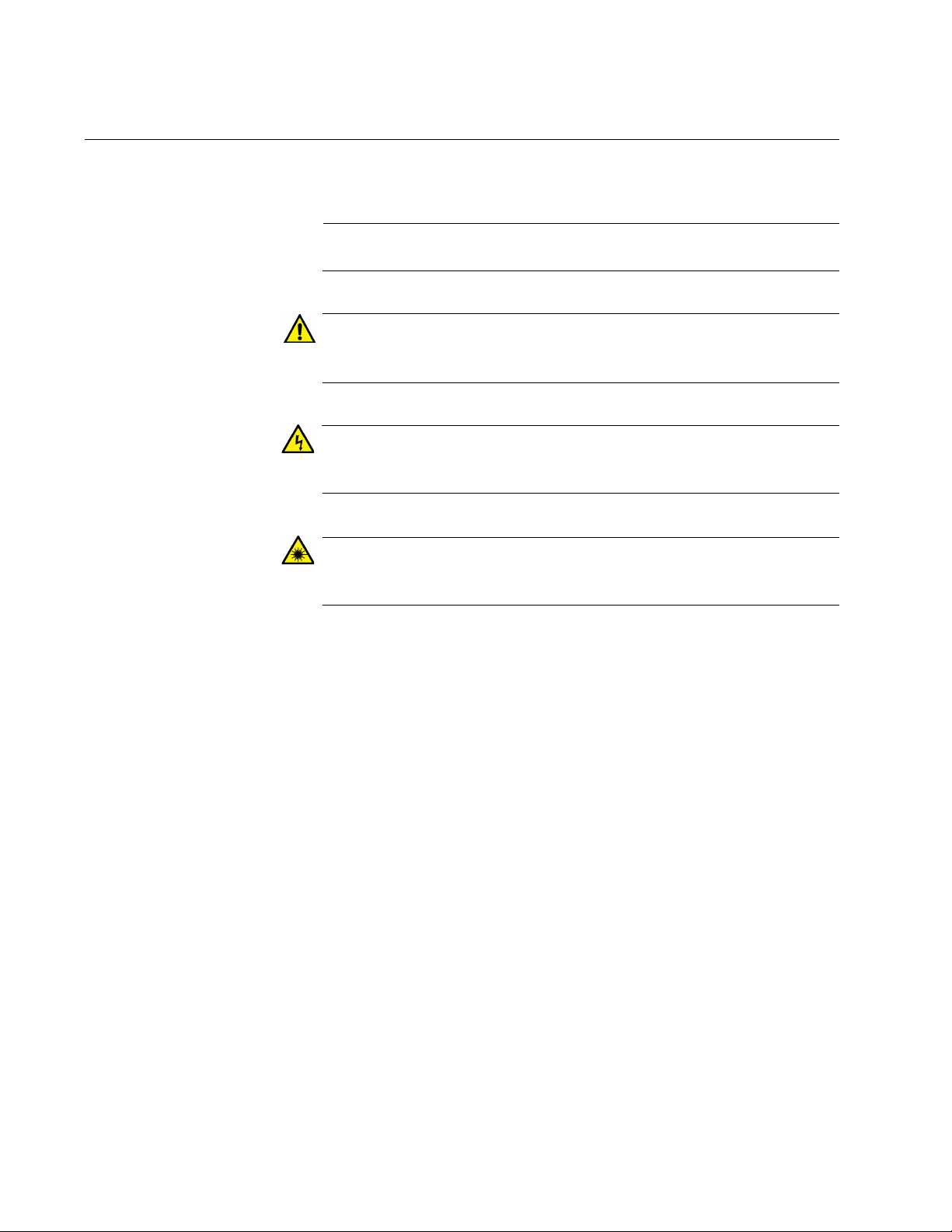
Note
Caution
Warning
Warning
This document uses the following conventions:
Notes provide additional information.
Cautions inform you that performing or omitting a specific action
may result in equipment damage or loss of data.
Warnings inform you that performing or omitting a specific action
may result in bodily injury.
Warnings inform you that an eye and skin hazard exists due to the
presence of a Class 1 laser device.
12
Page 13

Contacting Allied Telesis
If you need assistance with this product, you may contact Allied Telesis
technical support by going to the Support & Services section of the Allied
Telesis web site at www.alliedtelesis.com/support. You can find links for
the following services on this page:
❒ 24/7 Online Support - Enter our interactive support
center to search for answers to your questions in our
knowledge database, check support tickets, learn
about RMAs, and contact Allied Telesis technical
experts.
❒ USA and EMEA phone support - Select the phone
number that best fits your location and customer type.
❒ Hardware warranty information - Learn about Allied
Telesis warranties and register your product online.
❒ Replacement Services - Submit a Return Merchandise
Authorization (RMA) request via our interactive support
center.
AT-GS2002/SP Gigabit Ethernet to Fiber SFP Media Converter Installation Guide
❒ Documentation - View the most recent installation
guides, user guides, software release notes, white
papers and data sheets for your product.
❒ Software Updates - Download the latest software
releases for your product.
❒ For sales or corporate contact information, go to
www.alliedtelesis.com/purchase and select your
region.
13
Page 14

14
Page 15

Chapter 1
Overview
This chapter describes the AT-GS2002/SP Media Converter in the
following sections:
“Introduction” on page 16
“Front and Back Panels” on page 19
“Twisted-Pair Ports” on page 20
“SFP Port” on page 22
“LEDs” on page 23
“Power Supply” on page 27
15
Page 16

Chapter 1: Overview
Introduction
General Here are the basic features of the AT-GS2002/SP Media Converter:
The AT-GS2002/SP Media Converter is a 10/100/1000Base-TX copper to
SFP (Small Form-factor Pluggable) media converter. It does not require
software configuration or management.
MODE push button for MissingLink (ML), Smart Missing Link
(SML), and Link Test (LT) modes
LEDs for unit and port status
Transparent to VLAN packets
MAC address table up to 4KB
Automatic learning and aging
Supports jumbo packets up to 10240 bytes
DC receptacle power adapter provided
Twisted-Pair Port Here are the features of the twisted-pair port:
1 port
10Base-TX, 100Base-T and 1000Base-T compliant
IEEE 802.3u Auto-Negotiation compliant
Auto-MDI/MDIX
RJ-45 connector
100 meters (328 feet) maximum operating distance
IEEE 802.3x flow control in 10/100Base-TX full-duplex operation
IEEE 802.3x back pressure in 10/100Base-TX half-duplex
operation
IEEE803.3z 1000Base-T flow control
16
Page 17

AT-GS2002/SP Gigabit Ethernet to Fiber SFP Media Converter Installation Guide
Note
Note
Note
SFP Port Here are the features of the SFP port:
1 Port
100BaseX and 1000BaseFX compliant
IEEE 802.3x flow control in 100Base-TX full-duplex operation
IEEE 802.3x back pressure in 100Base-TX half-duplex operation
IEEE803.3z 1000Base-T flow control
SFP transceivers must be purchased separately. For a list of
supported transceivers, contact your Allied Telesis distributor or
reseller.
LEDs The AT-GS2002/SP Media Converter has the following LEDs:
Speed and link/activity LEDs for the both the twisted-pair port and
SFP slot
Installation
Options
Duplex LEDs
Mode LEDs
Power LED
Here are the installation options for the AT-GS2002/SP Media Converter:
Desk or tabletop installation
Wall mount installation
Wall mount installation requires that the AT-GS2002/SP Media
Converter be installed in an AT-TRAY1 Rack/Wall Mount Bracket.
Rack mount installation
Rack mount installation requires that the AT-GS2002/SP Media
Converter be installed in an AT-MCR12 Rack Mount Chassis, an
AT-TRAY4 Rack Mount Tray or an AT-TRAY1 Rack/Wall Mount
Bracket.
MAC Address
Table
Here are the basic features of the AT-GS2002/SP Media Converter MAC
address table:
Storage capacity of 4,000 MAC address entries
Automatic learning and aging
17
Page 18

Chapter 1: Overview
Dimensions Here are the physical dimensions of the AT-GS2002/SP Media Converter:
Width - 105 mm (4.12 in), Depth - 95mm (3.75 in), Height - 25mm
(1.0 in)
Environmental
Operating
Conditions
Here are the general environmental operating conditions for the ATGS2002/SP Media Converter:
Operating temperature range of 0° C to 40° C (32° F to 104° F)
Operating altitude: Up to 3,048 meters (10,000 feet)
Operating humidity range of 5% to 90% non-condensing
Storage temperature: -25° C to 70° C (-13° F to 158° F)
Storage humidity range of 5% to 95% non-condensing
18
Page 19

Front and Back Panels
Port 1
SFP
Port 2
Twisted-Pair
DIP
Switch
12 VDC
Input Connector
Figure 1 illustrates the front panel of the AT-GS2002/SP Media Converter.
Figure 2 illustrates the back panel of the AT-GS2002/SP Media Converter.
AT-GS2002/SP Gigabit Ethernet to Fiber SFP Media Converter Installation Guide
Figure 1. AT-GS2002/SP Front Panel
Figure 2. AT-GS2002/SP Back Panel
19
Page 20

Chapter 1: Overview
Note
Twisted-Pair Ports
The AT-GS2002/SP Media Converter features one twisted-pair port that is
10Base-T, 100Base-TX, and 1000Base-T compliant and has a maximum
operating distance of 100 m (328 feet). You can configure this port for
Auto-Negotiation or you can configure the port’s speed and duplex mode
manually. This port is labeled “Port 2” on the front panel. Refer to Figure 1
on page 19 for its location.
Refer to “DIP Switches” on page 26 and Table 7, “Rear Panel DIP
Switch Settings” on page 34 for information on how to configure the
Auto-Negotiation feature and the speed and duplex settings.
The twisted-pair port features an 8-pin RJ-45 connector. For the port
pinouts, refer to “Connectors and Port Pinouts” on page 50.
Cable
Specifications
The cable requirements for the twisted-pair port on the AT-GS2002/SP are
listed in Table 1.
Table 1. twisted-pair Cable Specifications for the AT-GS2002/SP
Cable Type 10Mbps 100Mbps 1000Mbps
Standard TIA/EIA 568-Bcompliant Category 3 shielded
or unshielded cabling with 100
Ohm impedance and a
frequency of 16 MHz.
Standard TIA/EIA 568-Acompliant Category 5 or TIA/
EIA 568-B-compliant
Enhanced Category 5 (Cat 5e)
shielded or unshielded cabling
with 100 Ohm impedance and
a frequency of 100 MHz.
Standard TIA/EIA 568-Bcompliant Category 6 or 6a
shielded cabling.
Yes Yes No
Yes Yes Yes
Yes Yes Yes
20
MDI/MDI-X
Mode
This twisted-pair port features auto-MDI/MDI-X when operating at 10, 100,
or 1000 Mbps. A port is automatically configured as MDI or MDI-X when it
is connected to another Ethernet port. Consequently, you can use a
straight-through or cross-over twisted-pair cable when connecting any
type of network device to this port on the media converter.
Page 21

AT-GS2002/SP Gigabit Ethernet to Fiber SFP Media Converter Installation Guide
Note
Note
Auto-Negotiation
Mode
When the Auto-Negotiation feature is enabled on the twisted-pair port, the
speed and duplex mode are automatically configured for you. Enabling
this feature assumes that the end-node device connected to a twisted-pair
port is also be configured for Auto-Negotiation mode. This feature insures
that the speed and duplex mode is matched on each end.
When the Auto-Negotiation feature is disabled, the port parameters must
be configured for the same speed and duplex mode as the link-partner.
If an end-node device connected to the AT-GS2002/SP twisted-pair
port is set to a fixed speed and duplex mode and the AT-GS2002/SP
has Auto-Negotiation enabled, a speed and duplex mismatch may
occur which can cause a reduction in the data flow. In this case,
disable the Auto-Negotiation feature on the AT-GS2002/SP.
Refer to “DIP Switches” on page 26 and Table 7, “Rear Panel DIP
Switch Settings” on page 34 for information on how to configure the
Auto-Negotiation feature, Speed and Duplex settings.
Flow Control and
Back Pressure
When two connected Ethernet device ports are set to different speeds, an
Ethernet device with the slower data rate capability may randomly be
flooded with more data than it can process and may need to signal the
opposite end-node device to stop sending data until it is ready to receive
more data again. How a port signals its end-node device to stop
transmitting data differs depending on the duplex mode of the Ethernet
ports.
A port operating in full-duplex mode uses PAUSE frames to momentarily
stop the transmission of data from the opposite end-node device.This is
specified in the IEEE 802.3x standard. Whenever a port wants an endnode device to stop transmitting data because it is being flooded by data, it
issues a PAUSE frame. This frame instructs the end-node device to
temporarily cease transmission. The port continues to issue PAUSE
frames until it is ready to receive data again from the opposite end-node
device. This is referred to as flow control.
A twisted-pair port operating at half-duplex mode stops its end-node
device from transmitting data by forcing a collision. A collision on an
Ethernet network occurs when two end-nodes attempt to transmit data
using the same data link at the same time. A collision causes the endnodes to momentarily stop sending data. When a port has received more
data than it can process, it needs to temporarily stop the opposite endnode device from transmitting data. The port does this by forcing a
collision, which stops the opposite end-node device from transmitting data.
When the port is ready to receive data again, the media converter stops
forcing collisions. This process is referred to as back pressure.
21
Page 22

Chapter 1: Overview
SFP Port
The AT-GS2002/SP Media Converter features one SFP port. This port is
labeled “Port 1” on the front panel. Refer to Figure 1 on page 19 for its
location.
The SFP port is capable of supporting a range of fiber SFP modules
offered by Allied Telesis. Refer to the AT-GS2002/SP product data sheet
for information concerning the specific SFP models supported and fiber
cable specifications. See “Contacting Allied Telesis” on page 5 for a link to
the AT-GS2002/SP product page.
22
Page 23

LEDs
SFP Port (1)
MODE Push Mode
Twisted-Pair
Power LED
LEDs
Button
LEDs
Port (2) LEDs
AT-GS2002/SP Gigabit Ethernet to Fiber SFP Media Converter Installation Guide
There are four types of LEDs on the AT-GS2002/SP Media Converter, as
shown in Figure 3:
SFP Port LEDs
Twisted-pair port LEDs
Status LED
Missing Link Mode LEDs
Figure 3. LEDs on the AT-GS2002 Series Converter
Power LED The Power LED indicates the operating status of the converter. Refer to
Figure 3 for the location of this status LED. This LED is described in
Table 2.
Table 2. Power LED
LED Color Description
PWR
Green
Off
Indicates that the unit power is ON.
Indicates that the converter power is OFF.
23
Page 24

Chapter 1: Overview
Note
MODE LEDs The MODE LEDs indicate the operating status of the three operation
modes: Link Test (LT), MissingLink (ML), and Smart MissingLink (SML).
These LEDs are described in Table 3.
Refer to Figure 3 on page 23 for the location of these LEDs.
Table 3. MODE LEDs
LED Color Description
Green
ML
Off
Green
SML
Off
LT Green
Off
MissingLink mode is enabled.
MissingLink mode is disabled.
Smart MissingLink mode is enabled.
Smart MissingLink mode is disabled.
Link Test mode is enabled.
Link Test mode is disabled.
24
Page 25

AT-GS2002/SP Gigabit Ethernet to Fiber SFP Media Converter Installation Guide
Note
Twisted-Pair Port
LEDs
The twisted-pair port LEDs indicate the operating status of the twisted-pair
port (Port 2) on the AT-GS2002 Series converter. Refer to Figure 3 on
page 23 for the location of these LEDs. The link, activity, and AutoNegotiation functions are defined in Table 4 and the speed LEDs are
defined in Table 5.
Refer to Table 7, “Rear Panel DIP Switch Settings” on page 34 to
configure the Auto-negotiation, speed, and duplex features
Table 4. Twisted-Pair Port LINK/ACT/AUTO-NEG LEDs
LED Color Description
Green A valid link is established on the port with its link-partner.
LINK
Blinking
Green
Indicates that when the AT-GS2002/SP Media Converter
is in SML mode, and the LINK has been dropped because
the LINK on the other port is lost.
Off A valid link is not established on the port with its link-
partner.
Blinking
ACT
Green
Off Indicates that there is no activity on the port.
AUTO
Green Indicates that the port Auto-Negotiation is ON.
NEG
Off Indicates that the port Auto-Negotiation is OFF.
-
Speed LEDs
10M 100M
Off Off
Green Off
Off Green
Green Green
Indicates that the port is transmitting and/or receiving data
packets.
Table 5. Twisted-Pair Port 100/1000 LEDs
Description
Indicates that the port is not linked to its end-node.
Indicates that the port is operating at 10 Mbps.
Indicates that the port is operating at 100 Mbps.
Indicates that the port is operating at 1000 Mbps.
25
Page 26

Chapter 1: Overview
Note
Fiber Optic Port
LEDs (SFP Slot)
The fiber optic port (Port 1) LEDs indicate the operating status of the SFP
slot on the AT-GS2002/SP Media Converter. Refer to Figure 3 on page 23
for the location of these LEDs. The functions of these LEDs are defined in
Table 6.
Refer to Figure 3 on page 23 for the location of these LEDs.
Table 6. Fiber Optic Port LEDs
LED Color Description
LINK
Green
Blinking
Green
Off
Indicates a valid link has been established
between the port and its end-node.
Indicates that when the AT-GS2002/SP Media
Converter is in SML mode, and the LINK on the
SFP port has been dropped because the LINK
on the other port is lost.
Indicates that there is no link between the port
and its end-node.
Green
ACT
Off
Green
100M
OFF
Green
1000M
OFF
Indicates that the port is transmitting and/or
receiving data packets.
Indicates that there is no activity on the port.
The port is operating at 100FX.
The port is not operating at 100FX.
The port is operating at 1000X.
The port is not operating at 1000X.
DIP Switches The DIP switches are used to manually configure the operating
characteristics of the RJ-45 twisted-pair port (Port 2), such as port speed,
duplex mode, Auto-Negotiation and the SFP port speed based on the SFP
module that is inserted into the SFP port.
The RJ-45 twisted-pair port is 10/100/1000Base capable. In forced mode,
you can configure the port of 10 or 100 Mbps only. By default, the 1000
Mbps speed is set to Auto-Negotiation only
For the DIP switch setting, refer to Table 7, “Rear Panel DIP Switch
Settings,” on page 34.
26
Page 27

Power Supply
Note
AT-GS2002/SP Gigabit Ethernet to Fiber SFP Media Converter Installation Guide
One multi-region 12VDC AC/DC power adapter is supplied in the shipping
carton with the AT-GS2002/SP Media Converter. It is illustrated in
Figure 4. This is an approved safety compliant AC power adapter for the
100 and 240V AC versions with an unregulated output of 12VDC.
Figure 4. AC/DC Power Adapter
For the AT-GS2002/SP Media Converter power requirements, refer
to the “Power Specifications” on page 49.
27
Page 28

Chapter 1: Overview
28
Page 29

Chapter 2
Installation
This chapter contains the following sections:
“Safety Precaution Review” on page 30
“Site Selection” on page 32
“Unpacking the AT-GS2002/SP Media Converter” on page 33
“Rear Panel DIP Switches Configuration” on page 34
“SFP Transceiver Installation” on page 35
“Desktop Installation” on page 37
“Rack Mount Installation” on page 39
“Cable Installation” on page 40
“Powering On the AT-GS2002/SP Media Converter” on page 43
29
Page 30

Safety Precaution Review
Note
Warning
Warning
Warning
Warning
Warning
Caution
Please review the following safety precautions before you begin to install
the chassis or any of its components.
The indicates that a translation of the safety statement is
available in a PDF document titled “Translated Safety
Statements”.
Class 1 laser device. L1
Do not stare into the laser beam. L2
To prevent electric shock, do not remove the cover. No userserviceable parts inside. This unit contains hazardous voltages and
should only be opened by a trained and qualified technician. To
avoid the possibility of electric shock, disconnect electric power to
the product before connecting or disconnecting the LAN cables.
E1
Do not work on equipment or cables during periods of lightning
activity. E2
Power cord is used as a disconnection device. To de-energize
equipment, disconnect the power cord. E3
Pluggable Equipment: The socket outlet should be installed near the
equipment and should be easily accessible. E5
Air vents must not be blocked and must have free access to the
room ambient air for cooling. E6
30
Page 31

AT-GS2002/SP Gigabit Ethernet to Fiber SFP Media Converter Installation Guide
Caution
Warning
Operating Temperature. This product is designed for a maximum
ambient temperature of 40° degrees C. E7
All Countries: Install this product in accordance with local and
National Electric Codes. E8
Circuit Overloading: Consideration should be given to the
connection of the equipment to the supply circuit and the effect that
overloading of circuits might have on overcurrent protection and
supply wiring. Appropriate consideration of equipment nameplate
ratings should be used when addressing this concern. E21
Warning
Mounting of the equipment in the rack should be such that a
hazardous condition is not created due to uneven mechanical
loading. E25
If installed in a closed or multi-unit rack assembly, the operating
ambient temperature of the rack environment may be greater than
the room ambient temperature. Therefore, consideration should be
given to installing the equipment in an environment compatible with
the manufacturer’s maximum rated ambient temperature (Tmra).
E35
Installation of the equipment in a rack should be such that the
amount of air flow required for safe operation of the equipment is not
compromised. E36
Reliable earthing of rack-mounted equipment should be maintained.
Particular attention should be given to supply connections other than
direct connections to the branch circuits (e.g., use of power strips).
E37
31
Page 32

Chapter 2: Installation
Note
Site Selection
Observe the following requirements when choosing a site for your
installation
If you plan to install the AT-GS2002/SP into an equipment rack,
you must first install the AT-GS2002/SP Media Converter in an ATMCR12 Rack Mount Chassis, AT-TRAY4 Rack Mount Tray or ATTRAY1 Rack/Wall Mount Bracket.
The AT-MCR12, AT-TRAY4 and AT-TRAY products are provided
separately and can be procured by contacting an Allied Telesis
sales representative. For a detailed description of the installation
procedures for these products, refer to the product documentation
on our www.alliedtelesis.com web site.
If you are installing the media converter on a table, verify that the
table is level and secure.
The power outlet for the media converter should be located near
the unit and should be easily accessible.
The site should provide for easy access to the ports on the front of
the media converter. This will make it easier for you to connect and
disconnect cables, as well as view the media converter’s LEDs.
Air flow around the unit and through its vents on the side and rear
should not be restricted so that the media converter can maintain
adequate cooling.
Do not place objects on top of the media converter.
Do not expose the media converter to moisture or water.
Ensure that the site is a dust-free environment.
You should use dedicated power circuits or power conditioners to
supply reliable electrical power to the network devices.
32
Page 33

AT-GS2002/SP Gigabit Ethernet to Fiber SFP Media Converter Installation Guide
Note
One AT-GS2002/SP Media Converter
One Multi-region
AC/DC Power Supply
Four rubber protective feet
Unpacking the AT-GS2002/SP Media Converter
To unpack the AT-GS2002/SP Media Converter, perform the following
procedure:
1. Remove all of the components from the shipping container.
Store the packaging material in a safe location. You must use the
original shipping material if you need to return the unit to Allied
Telesis.
2. The contents of the shipping container are shown in Figure 5. Verify
that you have received all the items shown. If any items are missing or
damaged, contact your Allied Telesis sales representative for
assistance.
Figure 5. Components within the AT-GS2002/SP Media Converter
Shipping Box
33
Page 34

Chapter 2: Installation
Note
Rear Panel DIP Switches Configuration
Before the AT-GS2002/SP Media Converter is installed, the rear panel
DIP switches must be configured for the two Ethernet ports. The DIP
switch are numbered 1 - 4 and each one controls a specific function for a
specific port. The port numbers assigned to each DIP switch are clearly
marked the table on the rear panel. The specific switch functions are given
in Table 7 for the possible settings.
The DIP switch location is shown in Figure 2 on page 19. Port 1
(SFP port) and Port 2 (twisted-pair port) are shown in Figure 1 on
page 19.
Table 7. Rear Panel DIP Switch Settings
DIP
Switch
Number
Port Setting Position Description
AUTO
12
NEG
DOWN Auto-negotiation on the twisted-pair port is ON.
SPEED
22
(Mbps)
DOWN The twisted-pair port operates at 100 Mbps.
DUPLEX
32
41SFP
MODE
DOWN The twisted-pair port operates in full-duplex mode
DOWN A 1000Base-X SFP module is installed.
When setting the DIP switches, consider the following:
Setting the Auto Neg DIP switch for the twisted-pair port to ON or
OFF enables or disables Auto-Negotiation for the port. If you
disable Auto-Negotiation, be sure to set the DIP switches for the
port’s speed and duplex mode to match the speed and duplex
mode of the end-node device connected to the converter’s copper
port.
If you enable Auto-Negotiation, be sure that the end-node device is
also configured for Auto-Negotiation.
UP Auto-negotiation on the twisted-pair port is OFF.
UP The twisted-pair port operates at 10 Mbps.
UP The twisted-pair port operates in half-duplex mode.
UP A 100Base-FX SFP module is installed.
34
Page 35

SFP Transceiver Installation
Note
Note
Warning
To install an SFP transceiver, perform the following procedure:
You should always install the transceiver before connecting the fiber
optic cables to it.
The transceiver can be hot-swapped; you do not need to power off
the media converter to install a transceiver.
1. Remove the transceiver from its shipping container and store the
packaging material in a safe location.
AT-GS2002/SP Gigabit Ethernet to Fiber SFP Media Converter Installation Guide
An SFP transceiver can be damaged by static electricity. Be sure to
observe all standard electrostatic discharge (ESD) precautions,
such as wearing an antistatic wrist strap, to avoid damaging the
transceiver.
2. Position the SFP transceiver with the label facing up.
3. With the handle on the transceiver oriented towards the top of the
media converter, slide the transceiver into the SFP slot until it clicks
into place. See Figure 6
Figure 6. Inserting the SFP
4. Verify that the handle on the transceiver is in the upright position or
oriented towards the top of the media converter. This secures the
transceiver and prevents it from being dislodged from the slot.
35
Page 36

Chapter 2: Installation
Note
Note
SFP transceivers are dust sensitive. Always keep the protective plug
in the optical bore when a fiber optic cable is not installed, or when
storing the SFP. When you do remove the plug, keep it for future
use.
Repeated and unnecessary removal and insertion of an SFP
module may lead to premature failure.
For information on the cable specifications of the SFP, consult the
documentation shipped with the SFP.
5. Go to “Cable Installation” on page 40.
36
Page 37

Desktop Installation
You may install the AT-GS2002/SP Media Converter on a desktop by
performing the following procedure:
1. Remove all equipment from the package and store the packaging
2. Turn the media converter over and place it on a table.
3. Attach the four rubber feet to the bottom of the media converter as
AT-GS2002/SP Gigabit Ethernet to Fiber SFP Media Converter Installation Guide
material in a safe place.
shown in Figure 7.
Figure 7. Attaching the Rubber Feet
4. Turn the media converter over and place it on a flat, secure surface
(such as a desk or table) leaving ample space around the unit for
ventilation.
5. Go to “SFP Transceiver Installation” on page 35 or “Cable Installation”
on page 40.
37
Page 38

Chapter 2: Installation
Note
Wall Mount Installation
For a wall mount installation, you must first install the AT-GS2002/SP into
an AT-TRAY1 Rack/Wall Mount Bracket.
The AT-TRAY product is provided separately and can be procured
by contacting an Allied Telesis sales representative. For a detailed
description of the installation procedures for this product, refer to the
product documentation on our www.alliedtelesis.com web site.
After the AT-GS2002/SP Media Converter is installed on the wall, go to
“Cable Installation” on page 40
38
Page 39

Rack Mount Installation
Note
For a rack mount installation of the AT-GS2002/SP into an equipment
rack, you must first install the AT-GS2002/SP into an AT-MCR12 Rack
Mount Chassis, AT-TRAY4 Rack Mount Tray or AT-TRAY1 Rack/Wall
Mount Bracket.
The AT-MCR12, AT-TRAY4 and AT-TRAY products are provided
separately and can be procured by contacting an Allied Telesis sales
representative. For a detailed description of the installation
procedures for these products, refer to the product documentation
on our www.alliedtelesis.com web site.
After the AT-GS2002/SP Media Converter is installed in the equipment
rack, go to “Cable Installation” on page 40
AT-GS2002/SP Gigabit Ethernet to Fiber SFP Media Converter Installation Guide
39
Page 40

Chapter 2: Installation
Cable Installation
Observe the following guidelines when connecting twisted-pair and fiber
optic cables to the ports on the media converter:
The cable specifications for the twisted-pair ports are given in
Table 1 on page 20.
The cable connector should fit snugly into the port on the media
converter. The tab on the connector should lock the connector into
place.
Because the twisted-pair ports have auto-MDI/MDI-X, you may use
straight-through or cross-over twisted-pair cables to connect any
type of Ethernet network devices to the media converter.
Refer to the cable specifications included in the SFP module data
sheet for the SFP module installed.
Connecting to the
Copper Port
To connect to the RJ-45 twisted-pair port on the AT-GS2002/SP Media
Converter, perform the following procedure:
1. Connect the RJ-45 twisted-pair cable to the 10/100/1000Base-TX port,
as shown in Figure 8.
Figure 8. Connecting to the RJ-45 Copper Ports
When connecting a twisted-pair cable to an RJ-45 twisted-pair port,
observe the following guidelines:
An RJ-45 connector should fit snugly into the port on the converter.
The tab on the connector should lock the connector into place.
40
You can use a straight-through or crossover twisted-pair cable to
connect any type of network device to a port on the converter.
2. Then connect the other end of the RJ-45 cable to the link partner.
3. Connect the fiber cable to the SFP module as described in
“Connecting to the SFP Module” on page 41
Page 41

AT-GS2002/SP Gigabit Ethernet to Fiber SFP Media Converter Installation Guide
Warning
Warning
Connecting to the
SFP Module
To connect to the SFP transceiver on the AT-GS2002/SP converter,
perform the following procedure:
Class 1 laser product. 1
Do not stare into the laser beam. 2
1. Remove the dust cover from the SFP transceiver, as shown in
Figure 9.
Figure 9. Removing the Dust Cover from the SFP Transceiver
2. Connect the appropriate optical cable to the transceiver, as shown in
Figure 10.
Figure 10. Connecting to the SFP Transceiver
41
Page 42

Chapter 2: Installation
When attaching a optical cable, be sure to observe the following
guidelines:
Be sure that the cable connector is firmly locked into place in the
port.
You should verify that you are using the appropriate type of optical
cabling for the SFP module you have installed.
You should verify that the operating specifications of the remote
fiber optic port are compatible with the SFP transceiver. For
example, you cannot connect a fiber optic SFP transceiver with a
maximum distance of 40 kilometers and an operating wavelength
of 1550 nanometers (nm) to a remote fiber optic port with an
maximum distance of only 10 kilometers and an operating
wavelength of 1310 nm.
The SFP transceiver consists of two connectors in one slot, as
shown in Figure 10. Each connector connects to a separate fiber
strand. One is for receiving data and the other is for transmitting
data. When connecting a fiber optic cable to a SFP module, be
sure that the receive fiber connector is connected to the transmitter
connector on the remote end-node device, and the transmit fiber
connector is connected to the receiver connector on the remote
node.
3. Then connect the other end of the optical cable to the link partner.
4. Power on the AT-GS2002/SP as instructed in “Powering On the ATGS2002/SP Media Converter” on page 43.
5. Power on the end-node devices.
42
Page 43

AT-GS2002/SP Gigabit Ethernet to Fiber SFP Media Converter Installation Guide
Note
Note
12 VDC
Input Connector
Powering On the AT-GS2002/SP Media Converter
To power on an AT-GS2002/SP Media Converter, perform the following
procedure:
The AC/DC power adapter shipped with the unit is not used if you
install the AT-GS2002 in an AT-MCR12 chassis. In this case, refer
to the AT-MCR12 Installation Guide for installation of the media
converter into the chassis and the power up instructions.
The AC/DC power adapter shipped with the unit is used if you install
the AT-GS2002 in an AT-TRAY4 or AT-TRAY1 chassis. The
following procedure applies in these cases.
1. Locate the 12 VDC input connector on the rear panel of the ATGS2002/SP Media Converter as shown in Figure 11.
Figure 11. Connecting Power Cord to an AT-GS2002 AC Powered
Chassis
2. Plug the DC end of the power cord to the power receptacle connector
labeled 12VDC.
43
Page 44

Chapter 2: Installation
Warning
3. Plug the AC/DC adapter to a power outlet, as shown in Figure 12.
Refer to Appendix A, “Technical Specifications” on page 49 for power
requirements.
Figure 12. Plugging an AC/DC Adapter to a Power Outlet
The power cord is used as a disconnection device. To de-energize
equipment, disconnect the power cord. 5
4. Verify that the PWR LED on the front of the converter is green. If the
LED is OFF, refer to “Troubleshooting” on page 45 for instructions.
5. Verify that the LINK LEDs for both the SFP port and the twisted-pair
port are green. If either LED is OFF, refer to “Troubleshooting” on
page 45 for instructions.
The chassis is now ready for network operations.
44
Page 45

Chapter 3
Note
Troubleshooting
This chapter contains information on how to troubleshoot the AT-GS2002/
SP Media Converter if a problem occurs. The following areas are
discussed:
For further assistance, please contact Allied Telesis Technical
Support at www.alliedtelesis.com/support.
“Power LED is Off” on page 46
“Twisted-Pair Port LINK/ACT LED is Off” on page 47
“SFP Port LINK/ACT LED Off” on page 48
AT-GS2002/SP Gigabit Ethernet to Fiber SFP Media Converter Installation Guide
45
Page 46

Chapter 3: Troubleshooting
Power LED is Off
Problem: The POWER LED on the front of the media converter is off.
Solutions: The unit is not receiving power. Try the following:
Verify that the power adapter is securely connected to a power
outlet and that the power adapter cable is securely connected to
the back of the converter.
Verify that the AC power outlet has power by connecting another
device to it.
Try connecting the unit to another power source.
Try using another power adapter.
Verify that the voltage from the power source is within the required
levels for your region.
46
Page 47

AT-GS2002/SP Gigabit Ethernet to Fiber SFP Media Converter Installation Guide
Note
Twisted-Pair Port LINK/ACT LED is Off
Problem: A twisted-pair port on the media converter is connected to a
network device but the port’s LINK/ACT LED is off.
Solutions: The port is unable to establish a link to a network device. Try
the following:
Verify that the network device connected to the twisted-pair port is
powered on and is operating properly.
Verify that the twisted-pair cable is securely connected to the
media converter port and to the port of the remote network device.
Verify that the port is connected to the correct twisted-pair cable.
This eliminates the possibility that the port is connected to the
wrong network device, such as a powered-off device.
Try connecting another network device to the twisted-pair port with
a different cable. If the twisted-pair port is able to establish a link,
then the problem is with the cable or the other network device.
Verify that the twisted-pair cable does not exceed 100 meters (328
feet).
Verify that you are using the appropriate category of twisted-pair
cable: Use Category 3 or better for 10 Mbps operation and
Category 5 and Category 5E for 100 and 1000 Mbps operation.
A 1000Base connection may require five to ten seconds to establish
a link.
47
Page 48

Chapter 3: Troubleshooting
SFP Port LINK/ACT LED Off
Problem: The LINK/ACT LED for an SFP transceiver is off.
Solutions: The fiber optic port on the transceiver is unable to establish a
link to a network device. Try the following:
Verify that the network device connected to the fiber optic port is
operating properly.
Verify that the fiber optic cable is securely connected to the port on
the media converter channel and to the port on the remote network
device.
Check that the SFP module is fully inserted in the slot.
Verify that the operating specifications of the fiber optic ports on
the SFP transceiver and the remote network device are
compatible.
Verify that the correct type of fiber optic cabling is being used.
Verify that the port is connected to the correct fiber optic cable.
This eliminates the possibility that the port is connected to the
wrong remote network device, such as a powered-off device.
Try connecting another network device to the fiber optic port using
a different cable. If the port is able to establish a link, then the
problem is with the cable or with the other network device.
If the remote network device is a managed device, use its
management firmware to determine whether its port is enabled.
Test the attenuation on the fiber optic cable with a fiber optic tester
to determine whether the optical signal is too weak (sensitivity) or
too strong (maximum input power).
Verify that Switch 4 of the rear panel DIP switch is set to the same
speed as the SFP module that is installed.
48
Page 49

AT-GS2002/SP Gigabit Ethernet to Fiber SFP Media Converter Installation Guide
Appendix A
Technical Specifications
The following specifications are for the AT-GS2002/SP Media Converter.
Physical Specifications
Table 8. Physical Specifications
Dimensions (H x W x D) 105 mm x 95 mm x 25 mm (4.12 in x 3.75 in x 1.0 in)
Weight 294 g (10.4 oz)
Environmental Specifications
Operating Temperature 0
Storage Temperature -25° C to 70° C (-13° F to 158° F)
Operating Humidity 5% to 90% non-condensing
Storage Humidity 5% to 95% non-condensing
Operating Altitude Range Up to 3,048 m (10,000 ft)
Power Specifications
Table 9. Environmental Specifications
°
C to 40° C (32° F to 104° F)
Figure 13. Power Specifications
Input Supply Voltage 12V DC
Rated Input Current 0.5A Maximum
Power Consumption 6 Watts Maximum
49
Page 50

Appendix A: Technical Specifications
Safety and Electromagnetic Emissions Certifications
Table 10. Safety and Electromagnetic Emissions Certifications
RFI Emissions FCC Class B, EN55022 Class B, C-TICK,
CD
Immunity EN55024
Electrical Safety EN60950 (TUV), UL 60950 (
Environmental
Compliance
Quality and Reliability
(MTBF @ 30
Connectors and Port Pinouts
This section lists the connectors and connector pinouts.
Figure 14 illustrates the pin layout for an RJ-45 connector and port.
Figure 14. RJ-45 Connector and Port Pin Layout
°
C)
CULUS
EU-RoHS compliant, WEEE, China
RoHS compliant
1,430,000 Hours
)
50
Table 11 lists the RJ-45 pin signals when a twisted-pair port is operating in
the MDI configuration.
Table 11. MDI Pin Signals (10Base-T or 100Base-TX)
Pin Signal
1TX+
2TX-
3RX+
6RX-
Table 12 lists the RJ-45 port pin signals when a twisted-pair port is
operating in the MDI-X configuration.
Page 51

AT-GS2002/SP Gigabit Ethernet to Fiber SFP Media Converter Installation Guide
Table 12. MDI-X Pin Signals (10Base-T or 100Base-TX)
Pin Signal
1RX+
2RX-
3TX+
6TX-
Table 13 lists the RJ-45 connector pins and their MDI/MDI-X pin signals
when the twisted-pair port is operating at 1000 Mbps.
Table 13. MDI and MDI-X Pin Signals (1000Base-TX)
MDI Configuration MDI-X Configuration
Pinout Pair Pinout Pair
1 Pair 1 + 1 Pair 2 +
2 Pair 1 - 2 Pair 2 -
3 Pair 2 + 3 Pair 1 +
4 Pair 3 + 4 Pair 4 +
5 Pair 3 - 5 Pair 4 -
6 Pair 2 - 6 Pair 1 -
7 Pair 4 + 7 Pair 3 +
8 Pair 4 - 8 Pair 3 -
51
Page 52

Appendix A: Technical Specifications
52
 Loading...