

Page 1
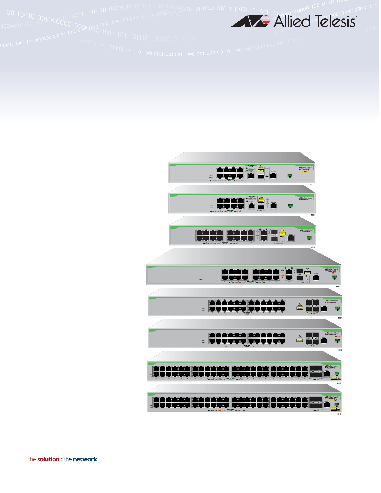
FS980M Series
FAST ETHERNET MANAGED SWITCHES
AT-FS980M/9 AT-FS980M/9PS
AT-FS980M/18 AT-FS980M/18PS
AT-FS980M/28 AT-FS980M/28PS
AT-FS980M/52 AT-FS980M/52PS
Installation Guide
613-002229 Rev. A
Page 2

Copyright 2017 Allied Telesis, Inc.
All rights reserved. No part of this publication may be reproduced without prior written permission from Allied Telesis, Inc.
Microsoft and Internet Explorer are registered trademarks of Microsoft Corporation. Netscape Navigator is a registered
trademark of Netscape Communications Corporation. All other product names, company names, logos or other
designations mentioned herein are trademarks or registered trademarks of their respective owners.
Allied Telesis, Inc. reserves the right to make changes in specifications and other information contained in this document
without prior written notice. The information provided herein is subject to change without notice. In no event shall Allied
Telesis, Inc. be liable for any incidental, special, indirect, or consequential damages whatsoever, including but not limited to
lost profits, arising out of or related to this manual or the information contained herein, even if Allied Telesis, Inc. has been
advised of, known, or should have known, the possibility of such damages.
Page 3

Electrical Safety and Emissions
Note
Note
Standards
This section contains the following:
“US Federal Communications Commission”
“Industry Canada”
“Emissions, Immunity and Electrical Safety Standards” on page 4
“Translated Safety Statements” on page 4
US Federal Communications Commission
Radiated Energy
This equipment has been tested and found to comply with the limits for a Class A digital device
pursuant to Part 15 of FCC Rules. These limits are designed to provide reasonable protection
against harmful interference when the equipment is operated in a commercial environment.
This equipment generates, uses, and can radiate radio frequency energy and, if not installed
and used in accordance with this instruction manual, may cause harmful interference to radio
communications. Operation of this equipment in a residential area is likely to cause harmful
interference in which case the user will be required to correct the interference at his own
expense.
Modifications or changes not expressly approved of by the manufacturer or the FCC, can void
your right to operate this equipment.
Industry Canada
Radiated Energy
This Class A digital apparatus complies with Canadian ICES-003.
Cet appareil numérique de la classe A est conforme à la norme NMB-003 du Canada.
3
Page 4

Emissions, Immunity and Electrical Safety Standards
Warning
RFI Emissions FCC Class A, EN55022 Class A, EN55032 Class A, CISPR 22 Class A,
CISPR 32 Class A, VCCI, RCM, CE
In a domestic environment this product may cause radio interference in which case the user
may be required to take adequate measures. E84
EMC (Immunity) EN55024, EN61000-3-2, EN61000-3-3
Electrical Safety UL60950-1 (
CULUS
), EN60950-1 (TUV)
Translated Safety Statements
Important: The indicates that translations of the safety statement are available in the PDF
document Translated Safety Statements posted on the Allied Telesis website at
alliedtelesis.com/support.
4
Page 5

Contents
Preface ..................................................................................................................................................................................7
Document Conventions ...................................................................................................................................................8
Contacting Allied Telesis .................................................................................................................................................9
Chapter 1: Overview ..........................................................................................................................................................11
Product Overview ..........................................................................................................................................................12
AT-FS980M/9 Switch .............................................................................................................................................12
AT-FS980M/9PS Switch ........................................................................................................................................13
AT-FS980M/18 Switch ...........................................................................................................................................14
AT-FS980M/18PS Switch ......................................................................................................................................15
AT-FS980M/28 Switch ...........................................................................................................................................16
AT-FS980M/28PS Switch ......................................................................................................................................17
AT-FS980M/52 Switch ...........................................................................................................................................18
AT-FS980M/52PS Switch ......................................................................................................................................19
SFP Slots ......................................................................................................................
Stacking Ports ........................................................................................................................................................20
Power Saving .........................................................................................................................................................20
Installation Options.................................................................................................................................................20
MAC Address Table ...............................................................................................................................................21
Management Software and Interfaces ...................................................................................................................21
Management Methods ...........................................................................................................................................21
Other Features .......................................................................................................................................................21
SFP Modules.................................................................................................................................................................22
Supported SFP Modules ........................................................................................................................................22
Guidelines for Using the AT-SPTX Module............................................................................................................22
Model Naming Conventions ..........................................................................................................................................23
10/100Base-TX Twisted Pair Ports ...............................................................................................................................24
Basic Features .......................................................................................................................................................24
Backpressure .........................................................................................................................................................24
Speed.....................................................................................................................................................................24
Duplex Mode ..........................................................................................................................................................24
Wiring Configuration...............................................................................................................................................25
Maximum Distance.................................................................................................................................................25
Power Over Ethernet..............................................................................................................................................25
Cable Requirements ..............................................................................................................................................26
Port Pinouts............................................................................................................................................................26
10/100/1000Base-T Twisted Pair Ports.........................................................................................................................27
Basic Features .......................................................................................................................................................27
Speed.....................................................................................................................................................................27
Duplex Mode ..........................................................................................................................................................27
Wiring Configuration...............................................................................................................................................28
Maximum Distance.................................................................................................................................................28
Power Over Ethernet..............................................................................................................................................28
Cable Requirements ..............................................................................................................................................29
Port Pinouts............................................................................................................................................................29
Combo Ports ....................................................................................................................
Power Over Ethernet.....................................................................................................................................................31
PoE Standards .......................................................................................................................................................31
Power Budget.........................................................................................................................................................31
Powered Device Classes .......................................................................................................................................32
.........................................20
.............................................30
5
Page 6

Contents
Port Prioritization ....................................................................................................................................................33
LEDs..............................................................................................................................................................................35
System LEDs..........................................................................................................................................................35
10/100Base-TX Twisted Pair Port LEDs ................................................................................................................36
10/100/1000Base-TX Twisted Pair Port LEDs .......................................................................................................37
SFP Slot LED .........................................................................................................................................................38
Console Port..................................................................................................................................................................39
Chapter 2: Installing the Switch .......................................................................................................................................41
Reviewing Safety Precautions.......................................................................................................................................42
Choosing a Site for the Switch ......................................................................................................................................46
Unpacking the Switch ....................................................................................................................................................47
Installing the Switch on a Table or Desktop...................................................................................................................49
Installing the Switch on a Wall .......................................................................................................................................50
Guidelines for Installing the Switch on a Wall.........................................................................................................50
What to Prepare for Installation..............................................................................................................................51
Installing the Switch on a Wall................................................................................................................................51
Installing the Switch in an Equipment Rack ...................................................................................................................55
What to Prepare for Installation..............................................................................................................................55
Installing the Switch in an Equipment Rack............................................................................................................55
Chapter 3: Cabling the Networking Ports ........................................................................................................................57
Cabling the Twisted Pair Ports ......................................................................................................................................58
Twisted Pair Ports ..................................................................................................................................................58
Installing Optional SFP Transceivers.............................................................................................................................60
Chapter 4: Powering On the Switch
Powering On the Switch ................................................................................................................................................64
Chapter 5: Troubleshooting ..............................................................................................................................................67
Appendix A: Technical Specifications .............................................................................................................................71
Physical Specifications ..................................................................................................................................................71
Environmental Specifications.........................................................................................................................................72
PoE Power Specifications .............................................................................................................................................73
Power Specifications .....................................................................................................................................................73
RJ-45 Twisted Pair Port Pinouts....................................................................................................................................74
RJ-45 Style Serial Console Port Pinouts .......................................................................................................................75
.................................................................................................................................63
6
Page 7

Preface
This guide contains the installation instructions for the FS980M Series of
Fast Ethernet switches. The switch models included in this manual are:
AT-FS980M/9
AT-FS980M/9PS
AT-FS980M/18
AT-FS980M/18PS
AT-FS980M/28
AT-FS980M/28PS
AT-FS980M/52
AT-FS980M/52PS
The preface contains the following sections:
“Document Conventions” on page 8
“Contacting Allied Telesis” on page 9
7
Page 8
Preface
Note
Caution
Warning
Document Conventions
This document uses the following conventions:
Notes provide additional information.
Cautions inform you that performing or omitting a specific action
may result in equipment damage or loss of data.
Warnings inform you that performing or omitting a specific action
may result in bodily injury.
8
Page 9

Contacting Allied Telesis
If you need assistance with this product, you may contact Allied Telesis
technical support by going to the Support & Services section of the Allied
Telesis web site at www.alliedtelesis.com/support. You can find links for
the following services on this page:
24/7 Online Support — Enter our interactive support center to
search for answers to your product questions in our knowledge
database, to check support tickets, to learn about RMAs, and to
contact Allied Telesis technical experts.
USA and EMEA phone support — Select the phone number that
best fits your location and customer type.
Hardware warranty information — Learn about Allied Telesis
warranties and register your product online.
Replacement Services — Submit a Return Merchandise
Authorization (RMA) request via our interactive support center.
FS980M Series Fast Ehternet Managed Switches Installation Guide
Documentation — View the most recent installation and user
guides, software release notes, white papers, and data sheets for
your products.
Software Downloads — Download the latest software releases for
your managed products.
For sales or corporate information, go to www.alliedtelesis.com/
purchase and select your region.
9
Page 10

Preface
10
Page 11

Chapter 1
Overview
This chapter contains the following sections:
“Product Overview” on page 12
“SFP Modules” on page 22
“Model Naming Conventions” on page 23
“10/100Base-TX Twisted Pair Ports” on page 24
“10/100/1000Base-T Twisted Pair Ports” on page 27
“Combo Ports” on page 30
“Power Over Ethernet” on page 31
“LEDs” on page 35
“Console Port” on page 39
11
Page 12
Chapter 1: Overview
Note
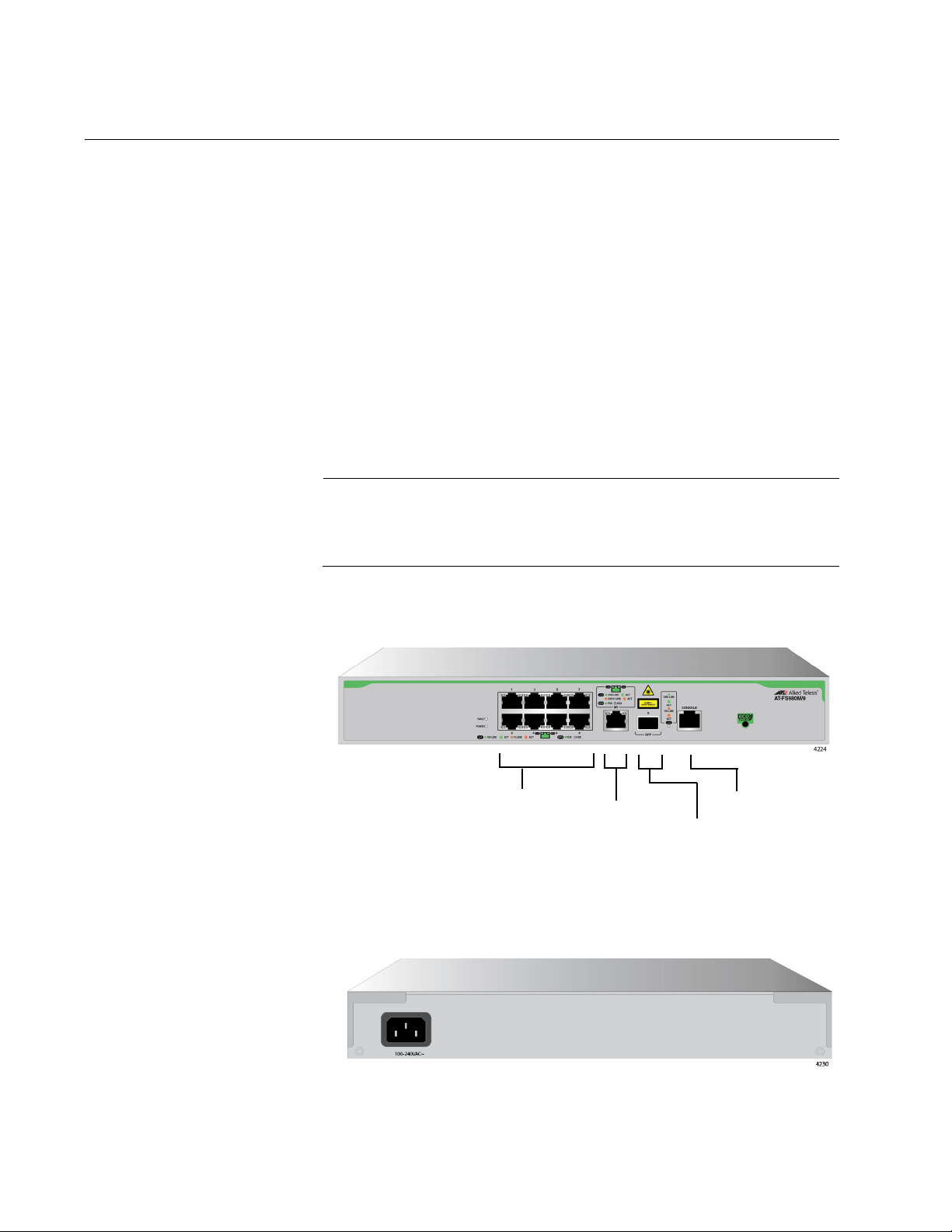
10/100Base-TX Ports
Console Port
10/100/1000Base-TX
Ports
SFP slot
Product Overview
The FS980M Series switch is a managed Fast Ethernet switch with SFP
slots. This series switch provides a simple solution to replace an edge
switch in small and medium-sized enterprises.
The eco-friendly feature automatically saves power consumption on each
port when the port has not established a link.
AT-FS980M/9
Switch
The AT-FS980M/9 switch is equipped with:
8 10/100Mbps twisted pair ports
One 10/100/1000Mbps twisted pair port (Combo port)
1 SFP slot (Combo port)
1 console port
The 10/100/1000Mbps twisted pair port and SFP slot form one pair
of combo ports. For more information, see “Combo Ports” on
page 30.
See Figure 1 for the port layout of the AT-FS980M/9 switch.
12
Figure 1. AT-FS980M/9 Switch Front Panel
The AT-FS980M/9 switch has an internal power supply with a single AC
power supply socket on the rear panel as shown in Figure 2.
Figure 2. AT-FS980M/9 Switch Rear Panel
Page 13
FS980M Series Fast Ehternet Managed Switches Installation Guide
Warning
Note
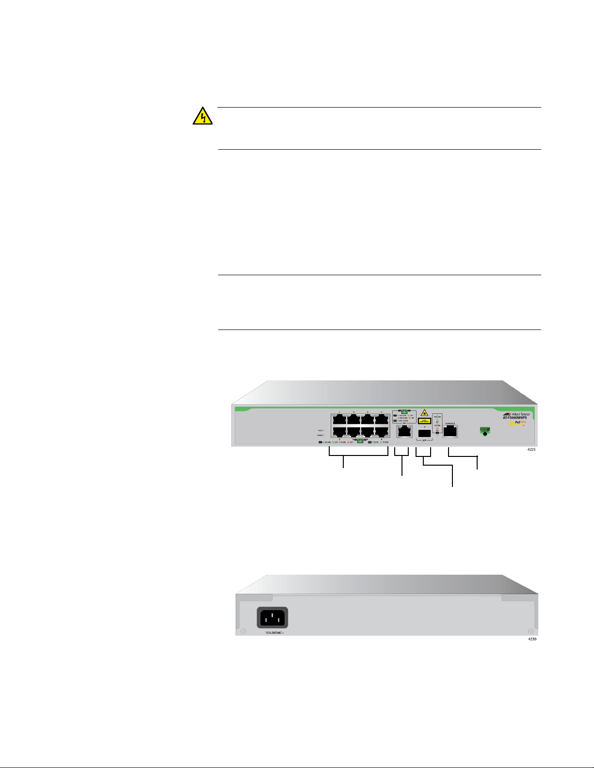
10/100Base-TX Ports
Console Port
10/100/1000Base-TX
Ports
SFP slot
A retainer clip is included in the accessory kit. To install the retainer clip,
see “Powering On the Switch” on page 64.
Power cord is used as a disconnection device. To de-energize
equipment, disconnect the power cord. E3
AT-FS980M/9PS
Switch
The AT-FS980M/9PS switch is equipped with:
8 PoE+ supported 10/100Mbps twisted pair ports
One 10/100/1000Mbps twisted pair port (Combo port)
1 SFP slot (Combo port)
1 console port
The 10/100/1000Mbps twisted pair port and SFP slot form one pair
of combo ports. For more information, see “Combo Ports” on
page 30.
See Figure 3 for the port layout of the AT-FS980M/9PS switch.
Figure 3. AT-FS980M/9PS Switch Front Panel
The AT-FS980M/9PS switch has an internal power supply with a single AC
power supply socket on the rear panel as shown in Figure 4.
Figure 4. AT-FS980M/9PS Switch Rear Panel
A retainer clip is included in the accessory kit. To install the retainer clip,
see “Powering On the Switch” on page 64.
13
Page 14
Chapter 1: Overview
Warning
Note
10/100Base-TX
Ports
Console Port
10/100/1000Base-TX
Ports
SFP slots
Power cord is used as a disconnection device. To de-energize
equipment, disconnect the power cord. E3
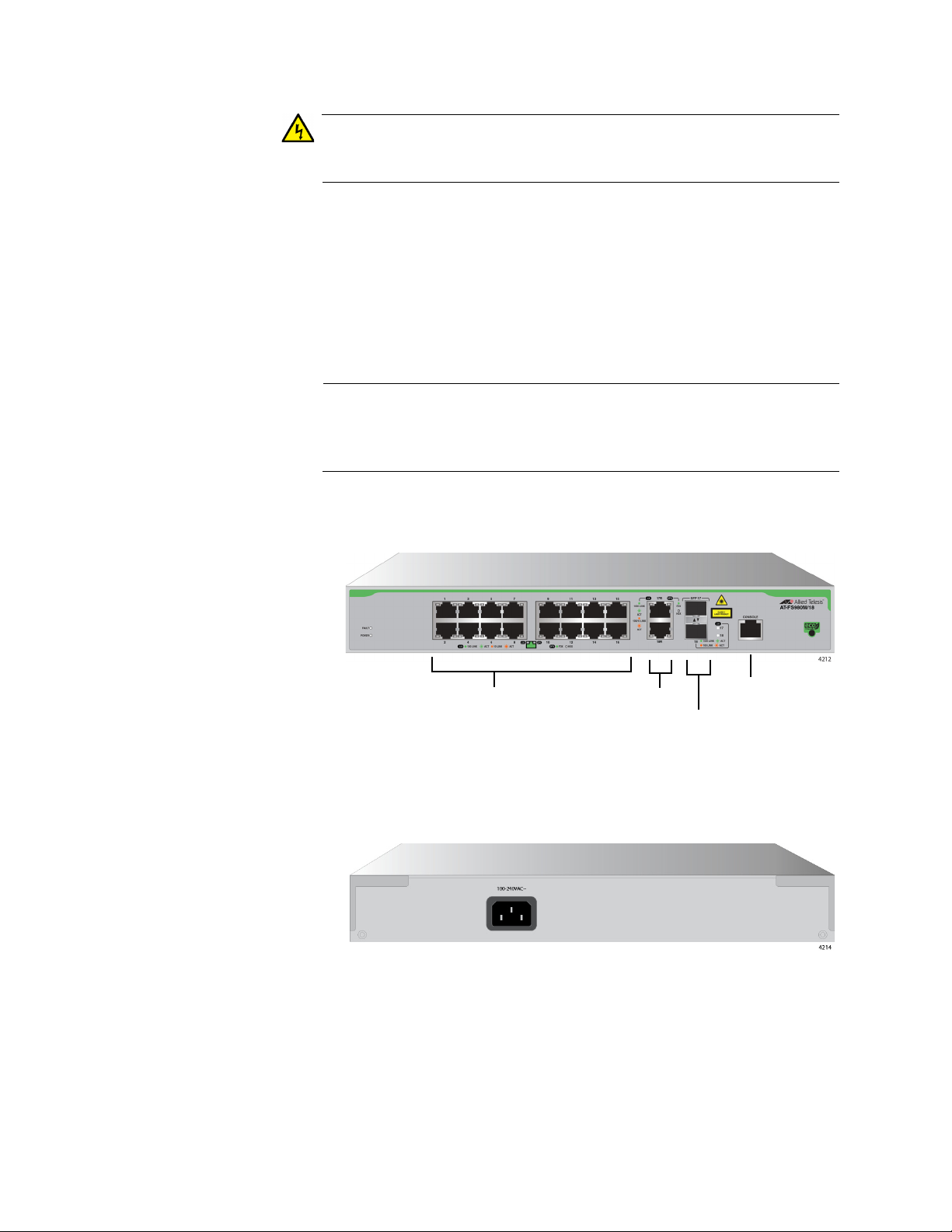
AT-FS980M/18
Switch
The AT-FS980M/18 switch is equipped with:
16 10/100Mbps twisted pair ports
2 10/100/1000Mbps twisted pair ports (Combo ports)
2 SFP slots (Combo ports)
1 console port
The 10/100/1000Mbps twisted pair ports and SFP slots form two
pairs of combo ports. For more information, see “Combo Ports” on
page 30.
See Figure 5 for the port layout of the AT-FS980M/18 switch.
14
Figure 5. AT-FS980M/18 Switch Front Panel
The AT-FS980M/18 switch has an internal power supply with a single AC
power supply socket on the rear panel as shown in Figure 6.
Figure 6. AT-FS980M/18 Switch Rear Panel
A retainer clip is included in the accessory kit. To install the retainer clip,
see “Powering On the Switch” on page 64.
Page 15
FS980M Series Fast Ehternet Managed Switches Installation Guide
Warning
Note
10/100Base-TX
Ports
Console Port
10/100/1000Base-TX
Ports
SFP slots
Power cord is used as a disconnection device. To de-energize
equipment, disconnect the power cord. E3
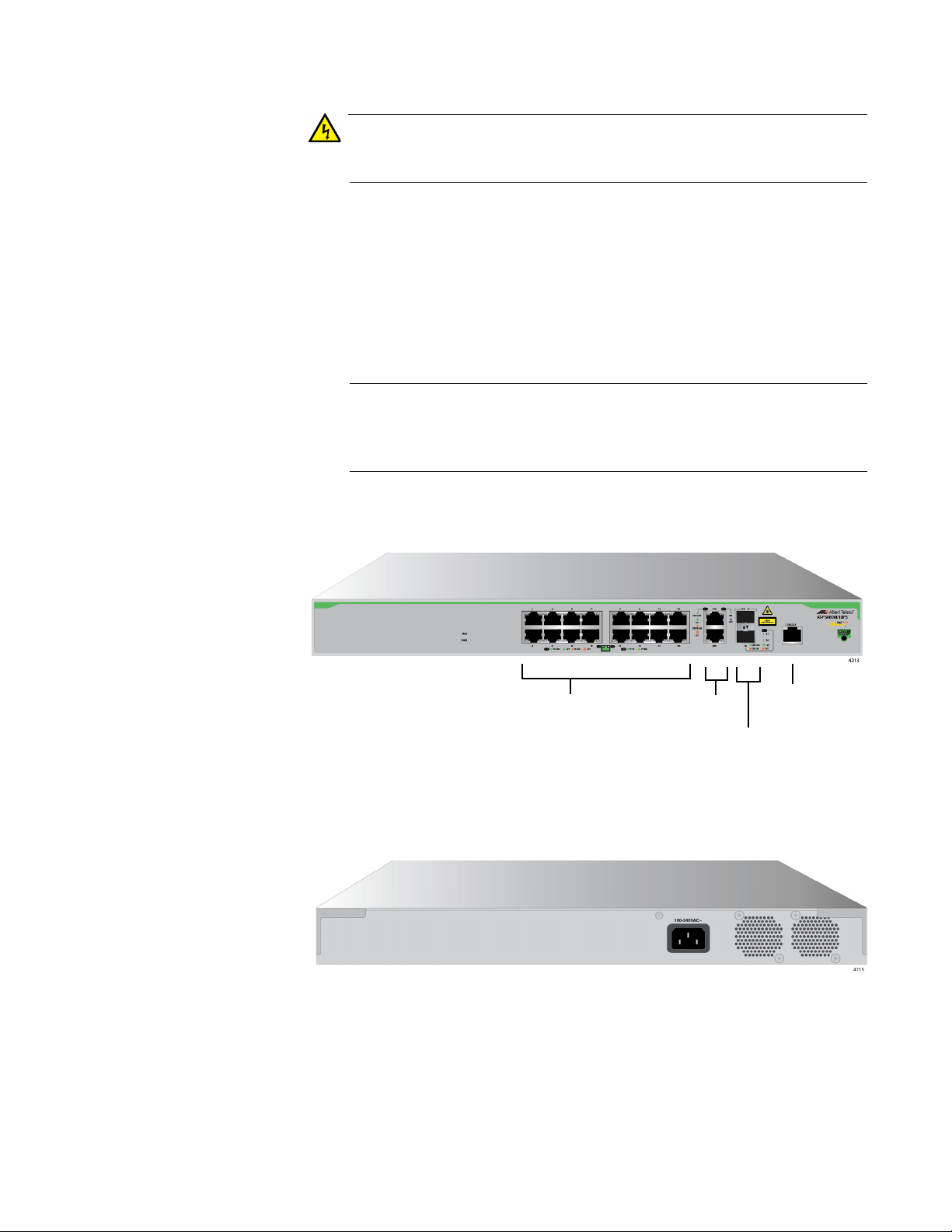
AT-FS980M/
18PS Switch
The AT-FS980M/18PS switch is equipped with:
16 PoE+ supported 10/100Mbps twisted pair ports
2 10/100/1000Mbps twisted pair ports (Combo ports)
2 SFP slots (Combo ports)
1 console port
The 10/100/1000Mbps twisted pair ports and SFP slots form two
pairs of combo ports. For more information, see “Combo Ports” on
page 30.
See Figure 7 for the port layout of the AT-FS980M/18PS switch.
Figure 7. AT-FS980M/18PS Switch Front Panel
The AT-FS980M/18PS switch has an internal power supply with a single
AC power supply socket on the rear panel as shown in Figure 8.
Figure 8. AT-FS980M/18PS Switch Rear Panel
A retainer clip is included in the accessory kit. To install the retainer clip,
see “Powering On the Switch” on page 64.
15
Page 16
Chapter 1: Overview
Warning
Note
Warning
10/100Base-TX
SFP Slots
Ports
Console Port
Power cord is used as a disconnection device. To de-energize
equipment, disconnect the power cord. E3
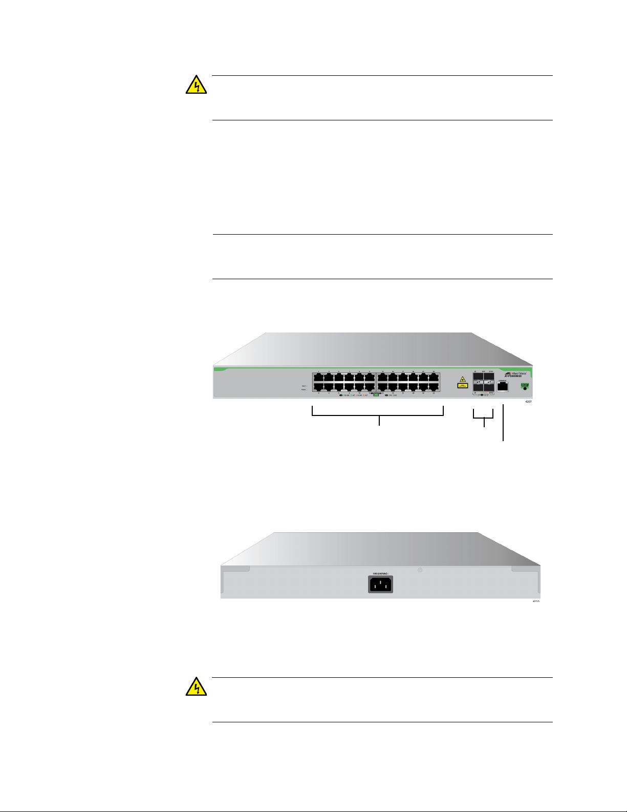
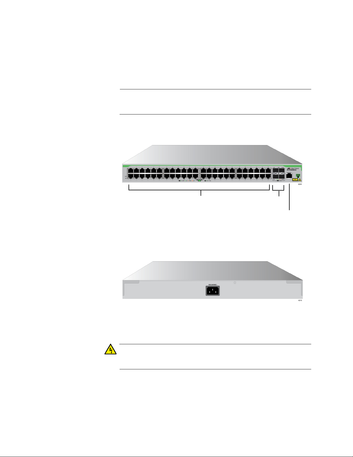
AT-FS980M/28
Switch
The AT-FS980M/28 switch is equipped with:
24 10/100Mbps twisted pair ports
4 SFP slots
1 console port
Two SFP slots can be used as stacking ports. For more information,
see “Stacking Ports” on page 20.
See Figure 9 for the port layout of the AT-FS980M/28 switch.
16
Figure 9. AT-FS980M/28 Switch Front Panel
The AT-FS980M/28 switch has an internal power supply with a single AC
power supply socket on the rear panel as shown in Figure 10.
Figure 10. AT-FS980M/28 Switch Rear Panel
A retainer clip is included in the accessory kit. To install the retainer clip,
see “Powering On the Switch” on page 64.
Power cord is used as a disconnection device. To de-energize
equipment, disconnect the power cord. E3
Page 17
FS980M Series Fast Ehternet Managed Switches Installation Guide
Note
Warning
10/100Base-TX
SFP Slots
PoE Ports
Console Port
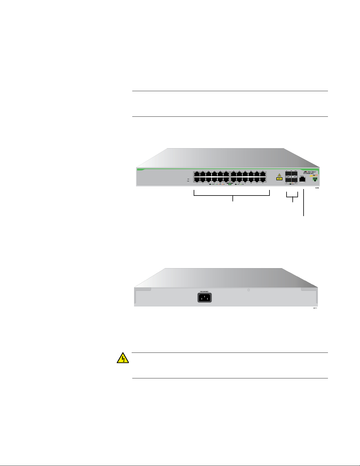
AT-FS980M/
28PS Switch
The AT-FS980M/28PS switch is equipped with:
24 PoE+ supported 10/100Mbps twisted pair ports
4 SFP slots
1 console port
Two SFP slots can be used as stacking ports. For more information,
see “Stacking Ports” on page 20.
See Figure 11 for the port layout of the AT-FS980M/28PS switch.
Figure 11. AT-FS980M/28PS Switch Front Panel
The AT-FS980M/28PS switch has an internal power supply with a single
AC power supply socket on the rear panel as shown in Figure 12.
Figure 12. AT-FS980M/28PS Switch Rear Panel
A retainer clip is included in the accessory kit. To install the retainer clip,
see “Powering On the Switch” on page 64.
Power cord is used as a disconnection device. To de-energize
equipment, disconnect the power cord. E3
17
Page 18
Chapter 1: Overview
Note
Warning
10/100Base-TX
SFP Slots
Ports
Console Port
AT-FS980M/52
Switch
The AT-FS980M/52 switch is equipped with:
48 10/100Mbps twisted pair ports
4 SFP slots
1 console port
Two SFP slots can be used as stacking ports. For more information,
see “Stacking Ports” on page 20.
See Figure 13 for the port layout of the AT-FS980M/52 switch.
Figure 13. AT-FS980M/52 Switch Front Panel
The AT-FS980M/52 switch has an internal power supply with a single AC
power supply socket on the rear panel as shown in Figure 14 on page 18.
Figure 14. AT-FS980M/52 Switch Rear Panel
A retainer clip is included in the accessory kit. To install the retainer clip,
see “Powering On the Switch” on page 64.
Power cord is used as a disconnection device. To de-energize
equipment, disconnect the power cord. E3
18
Page 19
FS980M Series Fast Ehternet Managed Switches Installation Guide
Note
Warning
10/100Base-TX
SFP Slots
PoE Ports
Console Port
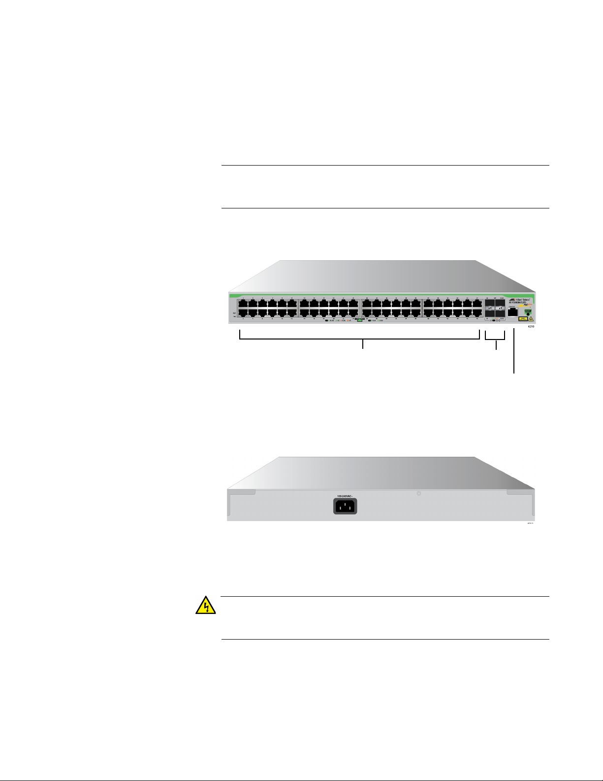
AT-FS980M/
52PS Switch
The AT-FS980M/52PS switch is equipped with:
48 10/100Mbps twisted pair ports including 24 PoE+ supported
ports
4 SFP slots
1 console port
Two SFP slots can be used as stacking ports. For more information,
see “Stacking Ports” on page 20.
See Figure 15 for the port layout of the AT-FS980M/52PS switch.
Figure 15. AT-FS980M/52PS Switch Front Panel
The AT-FS980M/52PS switch has an internal power supply with a single
AC power supply socket on the rear panel as shown in Figure 16.
Figure 16. AT-FS980M/52PS Switch Rear Panel
A retainer clip is included in the accessory kit. To install the retainer clip,
see “Powering On the Switch” on page 64.
Power cord is used as a disconnection device. To de-energize
equipment, disconnect the power cord. E3
19
Page 20
Chapter 1: Overview
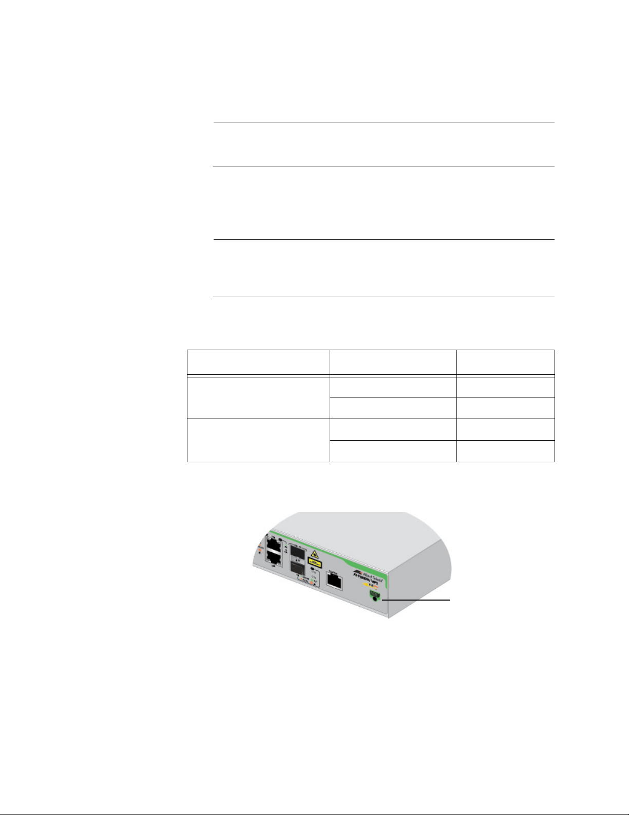
Note
Note
eco-friendly
Button
SFP Slots Here is the basic feature of the SFP slots:
Support only 1000Mbps speed.
SFP transceivers must be purchased separately. For a list of
supported transceivers, see “SFP Modules” on page 22.
Stacking Ports The two SFP slots can be used as stacking ports. Table 1 shows the
stacking ports and SFP slots per model.
The SFP slots can be used as stacking ports only on the ATFS980M/28, AT-FS980M/28PS, AT-FS980M/52 and
AT-FS980M/52PS switches.
Table 1. Stacking Ports
Model SFP Slot Stacking Port
AT-FS980M/28 and
AT-FS980M/28PS
AT-FS980M/52 and
AT-FS980M/52PS
27 S1
28 S2
51 S1
52 S2
Power Saving The power saving button on the front panel is used to turn on and off the
LEDs to conserve electricity. Figure 17 shows the power saving button.
Figure 17. FS980M Series Management Panels
20
Installation
Options
Here are the installation options:
Desktop or tabletop
Wall
19-inch equipment rack
Page 21

FS980M Series Fast Ehternet Managed Switches Installation Guide
MAC Address
Table
Management
Software and
Interfaces
Management
Methods
Here are the basic features of the MAC address tables of the switches:
Storage capacity of 16,384 MAC address entries
Automatic learning and aging
Here are the management software and management interfaces:
AlliedWare Plus Management Software
Command line interface
Web browser interface
Here are the methods for managing the switches:
Local management through the Console port
Remote Telnet and Secure Shell management
Remote HTTP and HTTPS web browser management
SNMPv1, v2c, and v3
Other Features The FS980M series switches have the following key features:
Allied Telesis Management Frame (AMF) node support
UDLD
Up to 256 entries for IGMP Snooping
Store-and-forward switching
Jumbo frame
21
Page 22

Chapter 1: Overview
Note
SFP Modules
Allied Telesis supports its SFP products. Before installing SFP modules
into the FS980M series switch, review a list of the supported SFP products
and restrictions.
Supported SFP
Modules
Here is a list of supported Allied Telesis SFP products:
AT-SPTX (See ”Guidelines for Using the AT-SPTX Module”.)
AT-SPSX
AT-SPSX/I
AT-SPSX2
AT-SPEX
AT-SPLX10
AT-SPLX10/I
AT-SPLX40
AT-SPZX80
AT-SPBD10-13
AT-SPBD10-14
AT-StackXS/1.0
AT-SP10TW1
The SFP slots support 1000Mbps speed only.
Guidelines for
Using the AT-
SPTX Module
22
Allied Telesis supports the AT-SPTX module on the AT-FS980M/28 switch
with some restrictions. The AT-FS980M/28 switch has four SFP slots.
Before using the AT-SPTX SFP module on the AT-FS980M/28 switch,
review the following guidelines:
The AT-FS980M/28 switch can have up to two AT-SPTX modules.
When you use two AT-SPTX modules on the he AT-FS980M/28
switch, you must use port 25 and port 26.
When two AT-SPTX modules are used on port 25 and port 26, you
can use only the AT-SP10TW1 or AT-StackXS/1.0 module on port
27 and port 28.
The operating temperature of the AT-FS980M/28 switch using the
AT-SPTX module must be between 0° C to 40° C (32° F to 104° F).
Page 23
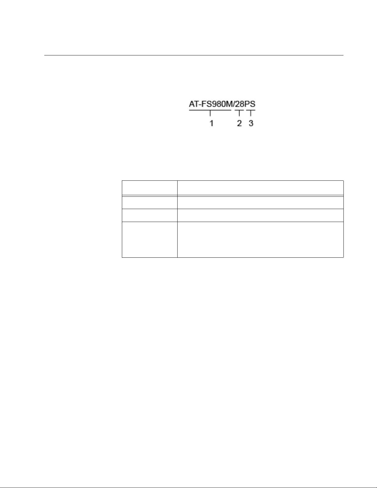
Model Naming Conventions
The hardware features of the switches are represented by the letters and
numbers in the model names. The conventions for the twisted pair
switches are identified in Figure 18.
Figure 18. Model Naming Conventions for the Twisted Pair Switches
The conventions are defined in Table 2.
Table 2. Model Naming Conventions for the Twisted Pair Switches
Convention Definition
FS980M Series Fast Ehternet Managed Switches Installation Guide
1 The series name
2 The number of 10/100Base-TX ports and SFP slots
3 The extension:
PS - This extension indicates support for Power over
Ethernet.
23
Page 24

Chapter 1: Overview
10/100Base-TX Twisted Pair Ports
The switches have 8, 16, 24, or 48 10/100Base-TX ports.
Basic Features Here are the basic features of the 10/100 Mbps twisted pair ports:
10Base-T and 100Base-TX compliant
IEEE 802.3u Auto-Negotiation compliant
Auto-MDI/MDIX
100 meters (328 feet) maximum operating distance
IEEE 802.3x flow control in 10/100Base-TX full-duplex operation
Support for jumbo frames up to 10KB
Support for store-and-forward switching
RJ-45 connectors
Backpressure Support for IEEE 802.3x backpressure in 10/100Base-TX half-duplex
operation depends upon a switch model:
Backpressure is supported on the AT-FS980M/9,
AT-FS980M/9PS, AT-FS980M/18, and AT-FS980M/18PS
switches.
To support backpressure on the AT-FS980M/28 or
AT-FS980M/28PS switch, you must upgrade the management
software to version 5.4.6-2.1 or later.
Backpressure is not supported on the AT-FS980M/52 and
AT-FS980M/52PS switches.
Speed The ports can operate at either 10 or 100 Mbps. The speeds may be set
manually using the management software or automatically with AutoNegotiation (IEEE 802.3u), the default setting.
Duplex Mode The twisted pair ports can operate in either half- or full-duplex mode. The
duplex mode determines the manner in which a port transmits data. A port
set to half-duplex can either transmit or receive data at one time, while a
port operating in full-duplex can transmit and receive data at the same
time. The best network performance is achieved with the full-duplex
setting, but not all network equipment is designed to support that duplex
mode.
24
The duplex modes, like port speeds, may be set manually using the
management software or automatically with Auto-Negotiation (IEEE
802.3u), the default setting.
Page 25

FS980M Series Fast Ehternet Managed Switches Installation Guide
Note
The speed and duplex mode settings of a port may be set independently
of each other. For example, a port may be configured such that its speed
is set manually while its duplex mode is established through AutoNegotiation.
A switch port that is connected to a network device that does not
support Auto-Negotiation and has a fixed duplex mode of full-duplex
should not set its duplex mode with Auto-Negotiation. A duplexmode mismatch in which a switch port and a network device operate
at different duplex modes, may occur. The duplex modes of switch
ports that are connected to network devices that do not support
Auto-Negotiation should be set manually through the management
software.
Wiring
Configuration
Maximum
Distance
Power Over
Ethernet
The wiring configuration of a port can be MDI or MDI-X. The wiring
configurations of a switch port and a network device connected with
straight-through twisted pair cabling have to be opposite, such that one
device is using MDI and the other MDI-X. For instance, a switch port has
to be set to MDI-X if it is connected to a network device set to MDI.
You may set the wiring configurations of the ports manually or let the
switch configure them automatically with auto-MDI/MDI-X (IEEE 802.3abcompliant). This feature enables the switch to negotiate with network
devices to establish the proper settings, so that the ports on the devices
are using different wiring configurations.
The ports have a maximum operating distance of 100 meters (328 feet).
The 10/100Base-TX ports on the AT-FS980M/9PS, AT-FS980M/18PS,
AT-FS980M/28PS, and AT-FS980M/52PS switches support Power over
Ethernet (PoE), which is a standard whereby DC power is provided by the
switch to network devices over the network twisted pair cables. The
switches support PoE (IEEE 802.3af) and PoE+ (IEEE 802.3at). For
background information, refer to “Power Over Ethernet” on page 31.
25
Page 26

Chapter 1: Overview
Cable
The cable requirements of the ports are given in Table 3.
Requirements
Table 3. Twisted Pair Cable for the 10/100Base-TX Ports
Cable Type
Standard TIA/EIA 568-Bcompliant Category 3 shielded
or unshielded cabling with 100
ohm impedance and a
frequency of 16 MHz.
Standard TIA/EIA 568-Acompliant Category 5 shielded
or unshielded cabling with 100
ohm impedance and a
frequency of 100 MHz.
Standard TIA/EIA 568-Bcompliant Enhanced Category
5 (Cat 5e) shielded or
unshielded cabling with 100
ohm impedance and a
frequency of 100 MHz.
10Mbps 100Mbps
Non-
PoE
YesNoNoNoNoNo
Yes Yes No Yes Yes No
Yes Yes Yes Yes Yes Yes
PoE PoE+
Non-
PoE
PoE PoE+
Standard TIA/EIA 568-B-
compliant Category 6 or 6a
shielded cabling.
Yes Yes Yes Yes Yes Yes
Port Pinouts See Table 20 on page 74 for the port pinouts of the 10/100Base-TX
twisted pair ports.
26
Page 27

FS980M Series Fast Ehternet Managed Switches Installation Guide
Note
10/100/1000Base-T Twisted Pair Ports
The AT-FS980M/9, AT-FS980M/9PS, AT-FS980M/18 and
AT-FS980M/18PS switches have one or two 10/100/1000Base-T ports.
The two ports of the AT-FS980M/9, AT-FS980M/9PS, AT-FS980M/18,
and AT-FS980M/18PS switches are paired with SFP slots to form combo
ports.
Basic Features Here are the basic features of the 10/100/1000 Mbps twisted pair ports:
10Base-T, 100Base-TX, and 1000Base-T compliant
IEEE 802.3u Auto-Negotiation compliant
Auto-MDI/MDIX
100 meters (328 feet) maximum operating distance
IEEE 802.3x flow control in 10/100Base-TX full-duplex operation
IEEE 802.3x backpressure in 10/100Base-TX half-duplex
operation
Support for jumbo frames up to 10KB
Support for store-and-forward switching
RJ-45 connectors
Speed The ports can operate at 10, 100, or 1000 Mbps. The speeds may be set
manually using the management software or automatically with AutoNegotiation (IEEE 802.3u), the default setting.
The ports must be set to Auto-Negotiation to function at 1000 Mbps.
They are not compatible with devices that are not IEEE 802.3u
compliant.
Duplex Mode The twisted pair ports can operate in either half- or full-duplex mode. The
duplex modes, like port speeds, may be set manually using the
management software or automatically with Auto-Negotiation (IEEE
802.3u), the default setting.
The speed and duplex mode settings of a port may be set independently
of each other. For example, a port may be configured such that its speed
is set manually while its duplex mode is established through AutoNegotiation.
27
Page 28

Chapter 1: Overview
Note
A switch port that is connected to a network device that does not
support Auto-Negotiation and has a fixed duplex mode of full-duplex
should not set its duplex mode with Auto-Negotiation. A duplexmode mismatch in which a switch port and a network device operate
at different duplex modes, may occur. The duplex modes of switch
ports that are connected to network devices that do not support
Auto-Negotiation should be set manually through the management
software.
Wiring
Configuration
Maximum
Distance
Power Over
Ethernet
The wiring configuration of a port operating at 10 or 100 Mbps can be MDI
or MDI-X. The wiring configurations of a switch port and a network device
connected with straight-through twisted pair cabling have to be opposite,
such that one device is using MDI and the other MDI-X. For instance, a
switch port has to be set to MDI-X if it is connected to a network device set
to MDI.
You may set the wiring configurations of the ports manually or let the
switch configure them automatically with auto-MDI/MDI-X (IEEE 802.3abcompliant). This feature enables the switch to automatically negotiate with
network devices to establish the proper settings.
The MDI and MDI-X settings do not apply when the ports are operating at
1000 Mbps.
The ports have a maximum operating distance of 100 meters (328 feet).
The 10/100/1000Base-T ports do not support PoE.
28
Page 29

FS980M Series Fast Ehternet Managed Switches Installation Guide
Cable
Requirements
The cable requirements of the ports are given in Table 4.
Table 4. Twisted Pair Cable for the 10/100/1000Base-T Ports
Cable Type 10Mbps 100Mbps 1000Mbps
Standard TIA/EIA 568-Bcompliant Category 3 shielded
or unshielded cabling with 100
ohm impedance and a
frequency of 16 MHz.
Standard TIA/EIA 568-Acompliant Category 5 shielded
or unshielded cabling with 100
ohm impedance and a
frequency of 100 MHz.
Standard TIA/EIA 568-Bcompliant Enhanced Category
5 (Cat 5e) shielded or
unshielded cabling with 100
ohm impedance and a
frequency of 100 MHz.
Yes No No
Yes Yes No
Yes Yes Yes
Standard TIA/EIA 568-B-
compliant Category 6 or 6a
shielded cabling.
Yes Yes Yes
Port Pinouts See Table 20 on page 74 and Table 21 on page 74 for the port pinouts of
the 10/100/1000Base-T twisted pair ports.
29
Page 30

Chapter 1: Overview
Combo Ports
The AT-FS980M/9, AT-FS980M/9PS, AT-FS980M/18, and
AT-FS980M/18PS switches have one or two pairs of combo ports. Each
combo port consists of one 10/100/1000Base-T twisted-pair port and one
slot for an SFP transceiver. The twisted-pair port of combo ports is
identified with the letter “R” for “Redundant” on the front panel of the
switch. The combo ports and SFP slots are listed in Table 5.
Table 5. Combo Ports
Combo Ports
Switch
Twisted-Pair Port SFP Slot
AT-FS980M/9 and
AT-FS980M/9PS
AT-FS980M/18 and
AT-FS980M/18PS
9R 9
17R 17
18R 18
The combo ports have the guidelines listed here:
Only one port in a pair, either the twisted-pair port or a
corresponding SFP module, can be active at a time.
The twisted-pair port is the active port when its SFP slot is empty,
or when an SFP module is installed, but has not established a link
to an end node.
The twisted-pair port automatically changes to the redundant
status mode when an SFP module establishes a link with an end
node.
A twisted-pair port automatically transitions back to the active
status when the link is lost on the SFP module.
In nearly all cases, a twisted-pair port and an SFP module share
the same configuration settings, including port settings, VLAN
assignments, access control lists, and spanning tree.
30
An exception to the shared settings is port speed. If you disable
Auto-Negotiation on a twisted-pair port and set the speed and
duplex mode manually, the speed reverts to Auto-Negotiation
when an SFP module establishes a link with an end node.
Page 31

Power Over Ethernet
PoE is used to supply power to network devices over the same twisted pair
cables that carry the network traffic. The main advantage of PoE is to
make it easier to install a network. The placement of network devices is
often limited by whether there are power sources nearby. This often limits
equipment placement or requires the added time and cost of having
additional electrical sources installed. But with PoE, you can install PoEcompatible devices wherever they are needed without having to worry
about whether there are power sources nearby.
A device that provides PoE to other network devices is referred to as
power sourcing equipment (PSE). The PoE switches act as PSE units by
adding DC power to the network cable, thus functioning as a central power
source for other network devices.
Devices that receive their power from a PSE are called powered devices
(PD). Examples include wireless access points, IP telephones, webcams,
and even other Ethernet switches.
FS980M Series Fast Ehternet Managed Switches Installation Guide
The switch automatically determines whether or not a device connected to
a port is a powered device. Ports that are connected to network nodes that
are not powered devices (that is, devices that receive their power from
another power source) function as regular Ethernet ports, without PoE.
The PoE feature remains activated on the ports but no power is delivered
to the devices.
PoE Standards The AT-FS980M/9PS, AT-FS980M/18PS, AT-FS980M/28PS, and AT-
FS980M/52PS switches support these PoE standards:
PoE (IEEE 802.3af): This standard provides up to 15.4 watts at the
switch port to support powered devices that require up to 12.95
watts.
PoE+ (IEEE 802.3at): This standard provides up to 30.0 watts at
the switch port to support powered devices that require up to 25.5
watts.
Power Budget The power budget is the maximum amount of power the switch can
provide at one time to the powered devices. The AT-FS980M/9PS, ATFS980M/18PS, AT-FS980M/28PS, and AT-FS980M/52PS switches
support both Power over Ethernet (PoE) and Power over Ethernet Plus
(PoE+) on 10/100Mbps twisted pair ports.
31
Page 32

Chapter 1: Overview
Table 6 shows PoE specifications for each model.
Table 6. PoE+ Switches
PoE+ Switch
Model
AT-FS980M/9PS 150 watts 0 to 4 8 5
AT-FS980M/18PS 250 watts 0 to 4 16 8
AT-FS980M/28PS 375 watts 0 to 4 24 12
AT-FS980M/52PS 375 watts 0 to 4 24 12
The power requirements of the PoE devices determine the maximum
number of devices the switch can support at one time. So long as the total
power requirements of the powered devices is less than the power budget
of the switch, the switch can supply power to all of the devices. If the total
power requirements exceed the power budget, the switch denies power to
one or more ports using a mechanism referred to as port prioritization.
To determine whether the power requirements of the PoE devices you
plan to connect to the switch exceed its power budget, refer to their
documentation for their power requirements and add the requirements
together. The switch should be able to power all of the devices
simultaneously as long as the total is below its power budget. If the total
exceeds the available power budget, you should consider reducing the
number of PoE devices so that all of the devices receive power.
Otherwise, the switch powers a subset of the devices, based on port
prioritization.
Power
Budget
Powered
Device
Classes
Number of
PoE Ports
Number of
PoE+ Ports
Powered Device
Classes
32
The switch can handle different power requirements on different ports.
This enables you to connect different classes of PoE equipment to the
ports on the switch.
Powered devices are grouped into the five classes listed in Table 7 on
page 33. The classes are based on the amount of power the devices
require. The switches support all five classes.
Page 33

FS980M Series Fast Ehternet Managed Switches Installation Guide
Note
Table 7. IEEE Powered Device Classes
Maximum Power
Class
Output from a Switch
PD Power Range
Port
0 15.4W 0.44W to 12.95W
1 4.0W 0.44W to 3.84W
2 7.0W 3.84W to 6.49W
3 15.4W 6.49W to 12.95W
4 30.0W 12.95W to 25.5W
PoE+ Class 4 powered devices (IEEE 802.3at) with a power range
of 12.95 to 25.5 watts must use LLDP to identify their power
requirements to the switch. Non-compliant PoE+ powered devices
that do not support LLDP will be limited to 802.3af (15.4 watts)
power levels.
Port
Prioritization
If the power requirements of the powered devices exceed the switch’s
power budget, the switch denies power to some ports based on a system
called port prioritization. You may use this mechanism to ensure that
powered devices critical to the operations of your network are given
preferential treatment by the switch in the distribution of power should the
demands of the devices exceed the available capacity.
There are three priority levels:
Critical
High
Low
Ports set to the Critical level, the highest priority level, are guaranteed
power before any of the ports assigned to the other two priority levels.
Ports assigned to the other priority levels receive power only if all the
Critical ports are receiving power. Ports that are connected to your most
critical powered devices should be assigned to this level. If there is not
enough power to support all the ports set to the Critical priority level, power
is provided to the ports based on port number, in ascending order.
The High level is the second highest level. Ports set to this level receive
power only if all the ports set to the Critical level are already receiving
power. If there is not enough power to support all of the ports set to the
High priority level, power is provided to the ports based on port number, in
ascending order.
33
Page 34

Chapter 1: Overview
The lowest priority level is Low. This is the default setting. Ports set to this
level only receive power if all of the ports assigned to the other two levels
are already receiving power. As with the other levels, if there is not enough
power to support all of the ports set to the Low priority level, power is
provided to the ports based on port number, in ascending order.
Power allocation is dynamic. Ports supplying power to powered devices
may cease power transmission if the switch’s power budget is at
maximum usage and new powered devices, connected to ports with
higher priorities, become active.
You can use port prioritization on dual power supply PoE switches to
protect your important networking devices from loss of power should one
of the power supplies fail or lose power. By limiting the power
requirements of the critical devices connected to a switch to less than 185
watts, the PoE power provided by a single power supply, a switch will
have sufficient power to support the critical devices even if it has only one
functional power supply.
34
Page 35

FS980M Series Fast Ehternet Managed Switches Installation Guide
Fault LED
Power LED
LEDs
Here are descriptions of the switch’s LEDs.
System LEDs The switch has power and fault LEDs as shown in Figure 20.
Figure 19. System LEDs
The System LEDs are described in Table 9.
Table 8. System LEDs
LED State Description
Off The switch is not receiving power.
PWR
Solid green Power is on.
Off The switch is operating normally or the
switch’s power is off.
Fault
Flashing orange An error occurs. The fan failed or the
temperature exceeded the limit.
35
Page 36

Chapter 1: Overview
Left LED
(Link/Activity)
Right LED
Left LED
(Link/Activity)
Right
LED
(
Link/Activity or PoE status)
(Link/Activity or PoE status)
10/100Base-TX
Twisted Pair Port
LEDs
The 10/100Base-TX twisted pair ports have link/activity and duplex mode/
PoE status LEDs. See Figure 20.
Figure 20. 10/100Base-TX Port LEDs
The LEDs are described in Table 9.
Table 9. 10/100Base-TX Port LEDs
LED State Description
Left
(Link/Activity)
Right
(Duplex Mode for
non-PoE switches)
Right
(PoE status for PoE
switches)
Off The port has not established a link to an
end node.
Solid green The port has established a link at
100Mbps speed.
Flashing
green
The port is receiving or transmitting
frames at 100Mbps speed.
Solid orange The port has established a link at 10Mbps
speed.
Flashing
orange
The port is receiving or transmitting
frames at 10Mbps speed.
Off The port is operating in half-duplex mode.
Solid green The port is operating in full-duplex mode.
Off No powered device (PD) is connected.
Solid green The connected PD is powered on.
Flashing
The PD has an error status.
green
36
Page 37

FS980M Series Fast Ehternet Managed Switches Installation Guide
L/A LED
DPX LED
DPX LEDL/A LED
10/100/1000Base-
TX Twisted Pair
Port LEDs
The 10/100/1000Base-TX twisted pair ports have link/activity and duplex
mode LEDs. Refer to Figure 20.
Figure 21. 10/100/1000Base-TX Port LEDs
The LEDs are described in Table 9.
Table 10. 10/100/1000Base-TX Port LEDs
LED State Description
L/A Off The port has not established a link to an
end node.
Solid green The port has established a link at
1000Mbps speed.
Flashing green The port is receiving or transmitting frames
at 1000Mbps speed.
Solid orange The port has established a link at
10/100Mbps speed.
Flashing orange The port is receiving or transmitting frames
at 10/100Mbps speed.
DPX Off The port is operating in half-duplex mode.
Solid green The port is operating in full-duplex mode.
37
Page 38

Chapter 1: Overview
Note
SFP Slot LEDs
SFP Slot
LED
SFP Slot LED Each SFP slot has one LED. Refer to Figure 22.
Figure 22. SFP Slot LEDs
The SFP slot LED is described in Table 11.
The last two SFP slots on the AT-FS980M/28, AT-FS980M/28PS,
AT-FS980M/52, and AT-FS980M/52PS switches can be used as
stacking ports. When an SFP slot is used as a stacking port, the
LED indicates the status of the link for stacking.
Table 11. SFP Slot LED
LED State Description
Link/
Activity
Off The SFP slot is empty or the SFP
module has not established a link to a
network device.
Solid green The port has established a link at
1000Mbps speed.
Flashing green The port is receiving or transmitting
frames at 1000Mbps speed.
38
Page 39

Console Port
Note
FS980M Series Fast Ehternet Managed Switches Installation Guide
The Console port is used to configure the features and parameter settings
of the switch. This type of management uses serial RS-232 and is
commonly referred to as local or out-of-band management because it is
not conducted over your network. To perform local management, you must
be at the location of the switch and must use the management cable
included with the switch.
To establish a local management session with the switch, you connect a
terminal or a personal computer with a terminal emulation program to the
Console port, which has an RJ-45 style (8P8C) connector, using the
provided management cable. The cable which has RJ-45 RJ-style (8P8C)
and DB-9 (D-sub 9-pin) connectors.
The Console port is set to the following specifications:
Default baud rate: 9600 bps
Data bits: 8
Parity: None
Stop bits: 1
Flow control: None
These settings are for a DEC VT100 or ANSI terminal, or an
equivalent terminal emulation program.
39
Page 40

Chapter 1: Overview
40
Page 41

Chapter 2
Installing the Switch
This chapter contains the following procedures:
“Reviewing Safety Precautions” on page 42
“Choosing a Site for the Switch” on page 46
“Unpacking the Switch” on page 47
“Installing the Switch on a Table or Desktop” on page 49
“Installing the Switch on a Wall” on page 50
“Installing the Switch in an Equipment Rack” on page 55
41
Page 42

Chapter 2: Installing the Switch
Note
Warning
Warning
Warning
Warning
Warning
Warning
Reviewing Safety Precautions
Please review the following safety precautions before you begin the
installation procedure.
The indicates that a translation of the safety statement is
available in a PDF document titled “Translated Safety Statements”
posted on the Allied Telesis website at www.alliedtelesis.com.
Class 1 Laser product. L1
Do not stare into the laser beam. L2
Do not look directly at the fiber optic cable ends or inspect the cable
ends with an optical lens. L6
To prevent electric shock, do not remove the cover. No userserviceable parts inside. This unit contains hazardous voltages and
should only be opened by a trained and qualified technician. To
avoid the possibility of electric shock, disconnect electric power to
the product before connecting or disconnecting the LAN cables.
E1
Do not work on equipment or cables during periods of lightning
activity. E2
Power cord is used as a disconnection device. To de-energize
equipment, disconnect the power cord. E3
42
Page 43

FS980M Series Fast Ethernet Managed Switches Installation Guide
Warning
Caution
Note
Warning
Caution
Caution
Class I Equipment. This equipment must be earthed. The power
plug must be connected to a properly wired earth ground socket
outlet. An improperly wired socket outlet could place hazardous
voltages on accessible metal parts. E4
Air vents must not be blocked and must have free access to the
room ambient air for cooling. E6
All Countries: Install product in accordance with local and National
Electrical Codes. E8
Only trained and qualified personnel are allowed to install or replace
this equipment. E14
Circuit Overloading: Consideration should be given to the
connection of the equipment to the supply circuit and the effect that
overloading of circuits might have on overcurrent protection and
supply wiring. Appropriate consideration of equipment nameplate
ratings should be used when addressing this concern. E21
Risk of explosion if battery is replaced by an incorrect type. Replace
only with the same or equivalent type recommended by the
manufacturer. Dispose of used batteries according to the
manufacturer’s instructions.
Attention: Le remplacement de la batterie par une batterie de type
incorrect peut provoquer un danger d’explosion. La remplacer
uniquement par une batterie du même type ou de type équivalent
recommandée par le constructeur. Les batteries doivent être
éliminées conformément aux instructions du constructeur. E22
43
Page 44

Chapter 2: Installing the Switch
Warning
Note
Caution
Note
Caution
Warning
Warning
Mounting of the equipment in the rack should be such that a
hazardous condition is not created due to uneven mechanical
loading. E25
Use dedicated power circuits or power conditioners to supply
reliable electrical power to the device. E27
The chassis may be heavy and awkward to lift. Allied Telesis
recommends that you get assistance when mounting the chassis in
an equipment rack. E28
If installed in a closed or multi-unit rack assembly, the operating
ambient temperature of the rack environment may be greater than
the room ambient temperature. Therefore, consideration should be
given to installing the equipment in an environment compatible with
the manufacturer’s maximum rated ambient temperature (Tmra).
E35
Installation of the equipment in a rack should be such that the
amount of air flow required for safe operation of the equipment is not
compromised. E36
Reliable earthing of rack-mounted equipment should be maintained.
Particular attention should be given to supply connections other than
direct connections to the branch circuits (e.g., use of power strips).
E37
44
To reduce the risk of electric shock, the PoE ports on this product
must not connect to cabling that is routed outside the building where
this device is located. E40
Page 45

FS980M Series Fast Ethernet Managed Switches Installation Guide
Caution
Warning
Warning
The unit does not contain serviceable components. Please return
damaged units for servicing. E42
When you remove an SFP module from this product, the case
temperature of the SFP may exceed 40° C (158° F). Exercise
caution when handling with unprotected hands. E43
Switches should not be stacked on top of one another on a table or
desktop because that could present a personal safety hazard if you
need to move or replace switches. E91
45
Page 46

Chapter 2: Installing the Switch
Warning
Choosing a Site for the Switch
Observe these requirements when planning the installation of the switch.
If you plan to install the switch in an equipment rack, the rack
should be safely secured so that it will not tip over. Devices in a
rack should be installed starting at the bottom, with the heavier
devices near the bottom of the rack.
If you plan to install the switch on a table, the table should be level
and stable.
The power outlet should be located near the switch and be easily
accessible.
The site should allow for easy access to the ports on the front of
the switch, so that you can easily connect and disconnect cables,
and view the port LEDs.
The site should allow for adequate air flow around the unit and
through the cooling vents on the front and rear panels. (The
ventilation direction in units that have a cooling fan is from front to
back, with the fan on the back panel drawing the air out of the unit.)
The site should not expose the switch to moisture or water.
The site should be a dust-free environment.
The site should include dedicated power circuits or power
conditioners to supply reliable electrical power to the network
devices.
The site should not be a wiring or utility box because the switch will
overheat and fail from inadequate airflow.
Switches should not be stacked on top of one another on a table or
desktop because that could present a personal safety hazard if you
need to move or replace switches. E91
46
Page 47

Unpacking the Switch
Note
To unpack the FS980M series switch, perform the following procedure:
1. Remove all components from the shipping package.
2. Place the switch on a level, secure surface.
3. Verify that the hardware components are included in your switch
FS980M Series Fast Ethernet Managed Switches Installation Guide
Store the packaging material in a safe location. You must use the
original shipping material if you need to return the unit to Allied
Telesis.
package. Table 12 shows a list of the hardware components.
Table 12. Components in the Bracket Kit
Brackets
Eight bracket
screws
Four rack
screws
Four rubber feet
AT-FS980M/9
AT-FS980M/9PS and
AT-FS980M/18
AT-FS980M/18PS
AT-FS980M/28 and
AT-FS980M/52
AT-FS980M/28PS
and
AT-FS980M/52PS
47
Page 48

Chapter 2: Installing the Switch
Table 12. Components in the Bracket Kit (Continued)
Four wall mount
screws
Four wall mount
anchors
One power
code retaining
clip
One regional
AC power cords
AT-FS980M/9
AT-FS980M/9PS and
AT-FS980M/18
AT-FS980M/18PS
AT-FS980M/28 and
AT-FS980M/52
AT-FS980M/28PS
and
AT-FS980M/52PS
One console
cable
4. If any item is missing or damaged, contact your Allied Telesis sales
representative for assistance.
48
Page 49

FS980M Series Fast Ethernet Managed Switches Installation Guide
Installing the Switch on a Table or Desktop
You may install the switch on a table or desktop. To install the switch on a
table or desktop, perform the following procedure:
1. Remove all the items from the packing.
2. Store the packaging material in a safe place.
3. Place the switch on a flat and secure surface, leaving ample space
around the switch for ventilation.
4. Proceed to Chapter 3, “Cabling the Networking Ports” on page 57 for
the cable installation.
49
Page 50

Chapter 2: Installing the Switch
Note
Installing the Switch on a Wall
The following FS980M series switches can be mounted on a wall using the
brackets that came with each switch:
AT-FS980M/9
AT-FS980M/9PS
AT-FS980M/18
AT-FS980M/18PS
AT-FS980M/28
AT-FS980M/52
The AT-FS980M/28PS and AT-FS980M/52PS switches can be
mounted on a wall using the AT-BRKT-J22 brackets. The AT-BRKTJ22 brackets must be purchased separately.
Guidelines for
Installing the
Switch on a Wall
Before planning to install the switch on a wall, review the following
guidelines:
The switch must be mounted on the wall in portrait orientation with
the front panel facing up. See Figure 23.
Figure 23. Correct Wall Installation
Mounting the front panel facing down, left or right on the wall is
incorrect. See Figure 24 on page 51 as examples.
50
Page 51

FS980M Series Fast Ethernet Managed Switches Installation Guide
Note
Figure 24. Incorrect Wall Installation
What to Prepare
for Installation
Installing the
You need the following items to install the switch on a wall:
One FS980M switch
One set of brackets
Screws to attach the brackets to the switch
Two rubber feet (only for AT-FS980M/18PS, AT-FS980M/28,
and AT-FS980M/52 switches)
Four screws and anchors that hold the switch to the wall
Phillip-head screwdriver (not provided)
Pencil (not provided)
A Phillip-head screwdriver and pencil are not included in the
shipping box.
Installation guidelines can be found in “Choosing a Site for the Switch” on
page 46.
To install the switch on a wall, perform the following procedure:
Switch on a Wall
1. Place all the items from the packaging on a work table.
2. Orient the brackets against the sides of the switch and secure them to
the switch with the eight screws as shown in Figure 25 on page 52.
51
Page 52

Chapter 2: Installing the Switch
Figure 25. Attaching the Brackets to the Switch
3. Go to the following step:
❑ For the AT-FS980M/9, AT-FS980M/9PS, and AT-FS980M/18
switches, go to Step 6.
These switches are not required to attach rubber feet.
❑ For the AT-FS980M/18PS, AT-FS980M/28, and AT-FS980M/52
switches, go to Step 4.
You must attach two rubber feet to fill the gap between the switch
and the wall for these switches.
4. Flip over the switch.
5. Attach two rubber feet at the corners where the brackets are not
installed. See Figure 26.
52
Figure 26. Attaching the Rubber Feet
Page 53

FS980M Series Fast Ethernet Managed Switches Installation Guide
6. Have another person hold the switch with the brackets at the wall
location where the switch is to be installed, while you use a pencil to
mark the wall with the locations of the four holes in the brackets. See
Figure 27.
Figure 27. Marking the Screw Hole Locations
7. Pre-drill the holes where you marked on the wall in Step 6.
8. Install the anchors into the holes.
9. Position the switch on the wall and drive screws through the holes to
attach the brackets on the wall. See Figure 28.
Figure 28. Driving the Screws through the Holes
53
Page 54

Chapter 2: Installing the Switch
10. Make sure that the two brackets are installed securely.
11. Proceed to Chapter 3, “Cabling the Networking Ports” on page 57 for
the cable installation.
54
Page 55

FS980M Series Fast Ethernet Managed Switches Installation Guide
Note
Caution
Installing the Switch in an Equipment Rack
The FS980M series switch can be installed in an equipment rack.
What to Prepare
for Installation
Installing the
Switch in an
Equipment Rack
You need the following items to install the switch in an equipment rack:
One FS980M switch
One set of brackets
Screws for brackets
Screws for an equipment rack
Phillip-head screwdriver (not provided)
Cross-head screwdriver (not provided)
Phillip-head and cross-head screwdrivers are not included in the
shipping box.
Installation guidelines can be found in “Choosing a Site for the Switch” on
page 46.
Here is the procedure for installing the switch in a 19-inch equipment rack.
The chassis may be heavy and awkward to lift. Allied Telesis
recommends that you get assistance when mounting the chassis in
an equipment rack. E28
1. Place all the items from the packaging on a work table.
2. Orient the brackets against the sides of the switch and secure them to
the switch with the eight screws as shown in Figure 29 on page 56.
55
Page 56

Chapter 2: Installing the Switch
Figure 29. Attaching the Equipment Rack Brackets
3. While another person holds the switch in the equipment rack, secure it
using the equipment rack screws. See Figure 30.
56
Figure 30. Mounting the Switch in an Equipment Rack
4. Go to Chapter 3, “Cabling the Networking Ports” on page 57 to
connect the network cables to the ports on the switch.
Page 57

Chapter 3
Cabling the Networking Ports
This chapter contains the following procedures:
“Cabling the Twisted Pair Ports” on page 58
“Installing Optional SFP Transceivers” on page 60
57
Page 58

Chapter 3: Cabling the Networking Ports
Cabling the Twisted Pair Ports
This section contains the guidelines to cabling the twisted pair and fiber
optic ports.
Twisted Pair
Ports
Here are the guidelines to cabling the 10/100Base-TX twisted pair ports:
The cable specifications are listed in Table 3 on page 26 and
Table 4 on page 29.
The connectors on the cables should fit snugly into the ports, and
the tabs should lock the connectors into place.
The default setting for the wiring configurations of the ports is auto-
MDI/MDI-X. The default setting is appropriate for switch ports that
are connected to 10/100Base-TX network devices that also
support auto-MDI/MDI-X.
The default auto-MDI/MDI-X setting is not appropriate for switch
ports that are connected to 10/100Base-TX network devices that
do not support auto-MDI/MDI-X and have a fixed wiring
configuration. For switch ports connected to those types of network
devices, you should disable auto-MDI/MDI-X and set the wiring
configurations manually.
The appropriate MDI/MDI-X setting for a switch port connected to a
10/100Base-TX network device with a fixed wiring configuration
depends on the setting of the network device and whether the
switch and network device are connected with straight-through or
crossover cable. If you are using straight-through twisted pair
cable, the wiring configurations of a port on the switch and a port
on a network device must be opposite each other, such that one
port uses MDI and the other MDI-X. For example, if a network
device has a fixed wiring configuration of MDI, you must disable
auto-MDI/MDI-X on the corresponding switch port and manually
set it to MDI-X. If you are using crossover twisted pair cable, the
wiring configurations of a port on the switch and a port on a
network device must be the same.
58
The default speed setting for the ports is Auto-Negotiation. This
setting is appropriate for ports connected to network devices that
also support Auto-Negotiation.
The default speed setting of Auto-Negotiation is not appropriate for
ports connected to 10/100Base-TX network devices that do not
support Auto-Negotiation and have fixed speeds. For those switch
ports, you should disable Auto-Negotiation and set the port’s
speed manually to match the speeds of the network devices.
The default duplex mode setting for the ports is Auto-Negotiation.
This setting is appropriate for ports connected to network devices
that also support Auto-Negotiation for duplex modes.
Page 59

FS980M Series Fast Ehternet Managed Switches Installation Guide
The default duplex mode setting of Auto-Negotiation is not
appropriate for ports connected to network devices that do not
support Auto-Negotiation and have a fixed duplex mode. You
should disable Auto-Negotiation on those ports and set their duplex
modes manually to avoid the possibility of duplex mode
mismatches. A switch port using Auto-Negotiation defaults to halfduplex if it detects that the end node is not using Auto-Negotiation,
which can result in a mismatch if the end node is operating at a
fixed duplex mode of full-duplex.
59
Page 60

Chapter 3: Cabling the Networking Ports
Warning
Installing Optional SFP Transceivers
Review the following guidelines before installing optional SFP transceivers
in the switch:
SFP transceivers can be hot-swapped while the switch is powered
on. However, you should always disconnect the fiber optic cable
first before removing a transceiver.
You should install the transceiver before connecting the fiber optic
cable.
Fiber optic transceivers are dust sensitive. Always keep the plug in
the optical bores when a fiber optic cable is not installed, or when
you store the transceiver. When you do remove the plug, keep it
for future use.
Unnecessary removal and insertion of a transceiver can lead to
premature failure.
A transceiver can be damaged by static electricity. Be sure to
observe all standard electrostatic discharge (ESD) precautions,
such as wearing an antistatic wrist strap, to avoid damaging the
device. E87
To install an SFP transceiver:
1. Remove the transceiver from its shipping container and store the
packaging material in a safe location.
2. If you are installing the transceiver in the top SFP slot, position the
transceiver with the Allied Telesis label facing up. If you are installing
the transceiver in the bottom slot, position the transceiver with the
label facing down.
3. Slide the transceiver into the slot until it clicks into place, as shown in
Figure 31 on page 61.
60
Page 61

FS980M Series Fast Ehternet Managed Switches Installation Guide
SFP Handle
Figure 31. Installing an SFP Transceiver
4. If the transceiver is installed in the top slot, verify that the handle is in
the upright position, as shown in Figure 32. If the transceiver is
installed in the bottom slot, verify that the handle is in the down
position.
Figure 32. Positioning the SFP Handle in the Upright Position
5. Connect the fiber optic cable to the SFP module, as shown in Figure
33 on page 62.
61
Page 62

Chapter 3: Cabling the Networking Ports
Figure 33. Connecting the Fiber Optic Cable to the SFP Module
6. Repeat this procedure if you have another SFP transceiver to install.
62
Page 63

Chapter 4
Powering On the Switch
This chapter contains the following procedures:
“Powering On the Switch” on page 64
63
Page 64

Chapter 4: Powering On the Switch
Powering On the Switch
Before powering on the switch, refer to “Power Specifications” on page 73
for the power specifications.To install the power cord retaining clip and
power on the switch, perform the following procedure:
1. Position the power cord retaining clip with the “u” part facing down,
press in the sides, and insert the ends of the clip into the holes in the
retaining bracket on the AC connector. See Figure 34.
64
Figure 34. Installing the Retaining Clip
2. Raise the retaining clip. See Figure 35 on page 65.
Page 65

FS980M Series Fast Ehternet Managed Switches Installation Guide
Figure 35. Raising the Retaining Clip
3. Connect the power cord to the connector. See Figure 36.
Figure 36. Plugging in the AC Power Cord
4. Lower the retaining clip to secure the power cord to the switch. See
Figure 37.
Figure 37. Lowering the Retaining Clip
65
Page 66

Chapter 4: Powering On the Switch
66
Page 67

Chapter 5
Note
Troubleshooting
This chapter contains suggestions on how to troubleshoot the switch if a
problem occurs.
For further assistance, please contact Allied Telesis Technical
Support at www.alliedtelesis.com/support.
Problem 1: All the LEDs on the switch are off.
Solutions: Try the following:
Press the eco-friendly button on the front panel to see if the switch
is operating in the low power mode with the LEDs off. You can also
toggle the LEDs off and on with the ECOFRIENDLY LED and NO
ECOFRIENDLY LED commands in the Global Configuration mode
of the command line interface.
Verify that the power cord is securely connected to the power
source and the AC connector on the back panel of the switch.
Verify that the power outlet has power by connecting another
device to it.
Try connecting the unit to another power source.
Try a different power cord.
Verify that the voltage from the power source is within the required
levels for your region.
Problem 3: A twisted pair port on the switch is connected to a network
device but the port’s LINK/ACT LED is off.
Solutions: The port is unable to establish a link to a network device. Try
the following:
Verify that the cable is securely connected to the ports on the
switch and network device.
Verify that the port is connected to the correct twisted pair cable.
Verify that the network device connected to the twisted pair port is
powered on and is operating properly.
67
Page 68

Chapter 5: Troubleshooting
Try connecting another network device to the twisted pair port with
a different cable. If the twisted pair port is able to establish a link,
then the problem is with the cable or the other network device.
Verify that the twisted pair cable does not exceed 100 meters (328
feet).
Verify that you are using the appropriate category of twisted pair
cable. The cable types are listed in Table 3 on page 26 and
Table 4 on page 29.
Problem 4: The LINK/ACT LED for an SFP transceiver is off.
Solutions: The fiber optic port on the transceiver is unable to establish a
link to a network device. Try the following:
Check that the SFP module is fully inserted in the slot.
Verify that the remote network device connected to the fiber optic
port is powered on and operating properly.
Verify that the fiber optic cable is securely connected to the ports
on the SFP module and remote network device.
Verify that the operating specifications of the fiber optic ports on
the SFP transceiver and the remote network device are
compatible.
Verify that the correct type of fiber optic cabling is being used.
Verify that the port is connected to the correct fiber optic cable.
Try connecting another network device to the fiber optic port using
a different cable. If the port is able to establish a link, then the
problem is with the cable or network device.
Use the switch’s management software to verify that the port is
enabled.
If the remote network device is a managed device, use its
management firmware to determine whether its port is enabled.
Test the attenuation of both directions on the fiber optic cable with
a fiber optic tester to determine whether the optical signal is too
weak (sensitivity) or too strong (maximum input power).
Problem 5: Network performance between a twisted pair port on the
switch and a network device is slow.
Solution: There might be a duplex mode mismatch between the port and
the network device. This occurs when a twisted pair port using AutoNegotiation is connected to a device with a fixed duplex mode of full
duplex. If this is the cause of the problem, adjust the duplex mode of the
port on the network device or switch so that both ports are using the same
duplex mode.
68
Page 69

FS980M Series Fast Ehternet Managed Switches Installation Guide
Problem 6: The switch functions intermittently.
Solutions: Check the system hardware status through the management
software:
Use the SHOW SYSTEM ENVIRONMENT command in the
Privileged Exec mode to verify that the input voltage from the
power source to the switch is stable and within the approved
operating range. The unit will shutdown if the input voltage
fluctuates above or below the approved operating range.
For switches that have a ventilation fan, use the SHOW SYSTEM
ENVIRONMENT command in the Privileged Exec mode to verify
that it is operating correctly.
Verify that the location of the switch provides adequate airflow. The
unit will shutdown if it is in danger of overheating.
69
Page 70

Chapter 5: Troubleshooting
70
Page 71

Appendix A
Technical Specifications
This section contains the following product technical specifications:
”Physical Specifications” on page 71
”Environmental Specifications” on page 72
”PoE Power Specifications” on page 73
”Power Specifications” on page 73
”RJ-45 Twisted Pair Port Pinouts” on page 74
”RJ-45 Style Serial Console Port Pinouts” on page 75
Physical Specifications
Dimensions (Width x Depth x Height)
Table 13. Product Dimensions
Model Dimensions
AT-FS980M/9
AT-FS980M/9PS
AT-FS980M/18 330 mm x 204 mm x 43.6 mm
AT-FS980M/18PS
AT-FS980M/28
AT-FS980M/52
AT-FS980M/28PS
AT-FS980M/52PS
210 mm x 275 mm x 42.5 mm
(8.3 in. x 10.8 in. x 1.7 in.)
(13 in. x 8 in. x 1.7 in.)
440 mm x 257 mm x 43.2 mm
(17.3 in. x 10.1 in. x 1.7 in.)
440 mm x 345 mm x 43.2 mm
(17.3 in. x 13.6 in. x 1.7 in.)
Weights
Table 14. Product Weights
Model Weight
AT-FS980M/9 2.0 kg (4.4 lb.)
AT-FS980M/9PS 2.5 kg (5.5 lb.)
71
Page 72

Appendix A: Technical Specifications
Table 14. Product Weights (Continued)
Model Weight
AT-FS980M/18 2.15 kg (4.7 lb.)
AT-FS980M/18PS 3.6 kg (7.9 lb.)
AT-FS980M/28 3.2 kg (7.1 lb.)
AT-FS980M/28PS 5.1 kg (11.2 lb.)
AT-FS980M/52 3.4 kg (7.5 lb.)
AT-FS980M/52PS 5.4 kg (11.9 lb.)
Ventilation
Table 15. Ventilation Requirements
Description Specification
Environmental Specifications
Description Specification
Operating Temperature*1 0° C to 50° C (32° F to 122° F)
Storage Temperature -20° C to 60° C (-4° F to 140° F)
Operating Humidity 5% to 80% noncondensing
Storage Humidity 5% to 95% noncondensing
Maximum Operating Altitude 3,048 m (10,000 ft.)
*1 The operating temperature of the AT-FS980M/28 switch using the AT-SPTX
module is between 0° C to 40° C (32° F to 104° F).
Recommended Minimum
Ventilation on All Sides
Table 16. Environmental Specifications
10 cm (4.0 in)
72
Page 73

PoE Power Specifications
FS980M Series Fast Ehternet Managed Switches Installation Guide
Table 17. PoE Power Specifications
AT-FS980M/9PS 150 watts 8 5
AT-FS980M/18PS 250 watts 16 8
AT-FS980M/28PS
AT-FS980M/52PS
Power Specifications
Maximum Power Consumptions
AT-FS980M/9 6.3 watts N/A
Product
Model
PoE Power
Available
375 watts 24 12
Table 18. Maximum Power Consumptions (watt)
Max Power Consumption
without PoE Load
Maximum PoE Ports Supported
IEEE 802.3af IEEE 802.3at
Max Power Consumption
with Full PoE Load
AT-FS980M/9PS 13 watts 190 watts
AT-FS980M/18 12 watts N/A
AT-FS980M/18PS 24 watts 320 watts
AT-FS980M/28 19 watts N/A
AT-FS980M/28PS 49 watts 520 watts
AT-FS980M/52 36 watts N/A
AT-FS980M/52PS 63 watts 540 watts
Input Voltages
Table 19. Input Voltages
Model Specification
All models 100-240 VAC
73
Page 74

Appendix A: Technical Specifications
RJ-45 Twisted Pair Port Pinouts
Figure 38 illustrates the pin layout of the RJ-45 connectors and ports.
Figure 38. RJ-45 Socket Pin Layout (Front View)
Table 20 lists the pin signals for 10 and 100 Mbps.
Table 20. Pin Signals for 10 and 100 Mbps
Pin MDI Signal MDI-X Signal
1TX+ RX+
2TX- RX-
3RX+ TX+
4 Not used Not used
5 Not used Not used
6RX- TX-
7 Not used Not used
8 Not used Not used
Table 21 lists the pin signals when a port operating at 1000 Mbps.
Table 21. Pin Signals for 1000 Mbps
Pinout Pair
1TP0 +
74
2TP0 -
3TP1 +
4TP2 +
Page 75

Table 21. Pin Signals for 1000 Mbps (Continued)
Pinout Pair
5TP2 -
6TP1 -
7TP3 +
8TP3 -
RJ-45 Style Serial Console Port Pinouts
Table 22 lists the pin signals of the RJ-45 style serial Console port.
Table 22. RJ-45 Pin Signals
FS980M Series Fast Ehternet Managed Switches Installation Guide
Pin Signal
1 Request to send
2 Not used
3 Transmit Data
4 Ground
5 Ground
6 Receive Data
7 Not used
8 Clear to send
75
Page 76

Appendix A: Technical Specifications
76
 Loading...