

Page 1

Fast Ethernet
WebSmart Switch
AT-FS750/24POE
Installation Guide
613-001269 Rev. A
Page 2

Copyright © 2010 Allied Telesis, Inc.
All rights reserved. No part of this publication may be reproduced without prior written permission from Allied Telesis, Inc.
Allied Telesis and the Allied Telesis logo are trademarks of Allied Telesis, Incorporated. All other product names, company names, logos or
other designations mentioned herein are trademarks or registered trademarks of their respective owners.
Allied Telesis, Inc. reserves the right to make changes in specifications and other information contained in this document without prior
written notice. The information provided herein is subject to change without notice. In no event shall Allied Telesis, Inc.be liable for any
incidental, special, indirect, or consequential damages whatsoever, including but not limited to lost profits, arising out of or related to this
manual or the information contained herein, even if Allied Telesis, Inc. has been advised of, known, or should have known, the possibility of
such damages.
Page 3

Electrical Safety and Emissions Standards
This product meets the following standards.
U.S. Federal Communications Commission
Radiated Energy
Note: This equipment has been tested and found to comply with the limits for a Class A digital device pursuant to Part 15
of FCC Rules. These limits are designed to provide reasonable protection against harmful interference when the
equipment is operated in a commercial environment. This equipment generates, uses, and can radiate radio frequency
energy and, if not installed and used in accordance with this instruction manual, may cause harmful interference to radio
communications. Operation of this equipment in a residential area is likely to cause harmful interference in which case
the user will be required to correct the interference at his own expense.
Note: Modifications or changes not expressly approved of by the manufacturer or the FCC, can void your right to operate
this equipment.
Industry Canada
This Class A digital apparatus complies with Canadian ICES-003.
Cet appareil numérique de la classe A est conforme à la norme NMB-003 du Canada.
RFI Emissions FCC Class A, EN55022 Class A, CISPR Class A, C-TICK, CE
Warning: In a domestic environment this product may cause radio interference in
which case the user may be required to take adequate measures.
Immunity EN55024
Electrical Safety EN60950-1 (TUV), UL 60950-1 (
CULUS
)
Laser Safety EN60825
3
Page 4

Translated Safety Statements
Important: The indicates that a translation of the safety statement is available in a PDF
document titled “Translated Safety Statements” on our web site.
Go to http://www.alliedtelesis.com/support/software
and this product under Product Name. You can view this document online or download it onto a local
workstation or server.
. Select “Switches” under Product Category
4
Page 5

Contents
Preface................................................................................................................................................................................ 11
Safety Symbols Used in this Document................................................................................................................................12
Where to Find Web-based Guides .......................................................................................................................................13
Contacting Allied Telesis ......................................................................................................................................................14
Online Support ..............................................................................................................................................................14
Email and Telephone Support .......................................................................................................................................14
Warranty........................................................................................................................................................................14
Returning Products........................................................................................................................................................14
For Sales or Corporate Information...............................................................................................................................14
Management Software Updates ...........................................................................................................................................15
Chapter 1: Overview ..........................................................................................................................................................17
Features ...............................................................................................................................................................................18
Front and Back Panels .........................................................................................................................................................19
Ports .....................................................................................................................................................................................20
Twisted Pair Ports .........................................................................................................................................................20
Uplink Combo Ports ......................................................................................................................................................20
Eco-friendly Switch ...............................................................................................................................................................21
LEDs.....................................................................................................................................................................................22
System LEDs.................................................................................................................................................................22
10/100Base-T POE Port LEDs......................................................................................................................................23
10/100Base-T Non-POE Port LEDs ..............................................................................................................................24
Uplink Combo Port LEDs ..............................................................................................................................................25
Power Supply .......................................................................................................................................................................26
Power over Ethernet.............................................................................................................................................................27
Power Budgeting ...........................................................................................................................................................27
Implementation..............................................................................................................................................................28
Ethernet Switching Basics ....................................................................................................................................................29
MAC Address Table ......................................................................................................................................................29
Duplex Mode ....................................................................................................................
Store and Forward.........................................................................................................................................................30
Back Pressure and Flow Control...................................................................................................................................30
.............................................30
Chapter 2: Installation .......................................................................................................................................................33
Reviewing Safety Precautions..............................................................................................................................................34
Selecting a Site for the Switch..............................................................................................................................................37
Cable Specifications .............................................................................................................................................................38
Twisted Pair Ports .........................................................................................................................................................38
SFP Ports ......................................................................................................................................................................38
Unpacking the Switch ...........................................................................................................................................................39
Installing the Switch on a Desktop ........................................................................................................................................40
Installing the Switch on a Wall ..............................................................................................................................................41
Installing a Switch in a Rack .................................................................................................................................................44
Installing an SFP Transceiver...............................................................................................................................................46
Cabling and Powering On the Switch ...................................................................................................................................48
Connecting the Twisted Pair Cables .............................................................................................................................48
Connecting the Fiber Optic Cables ...............................................................................................................................49
Powering On the Switch ................................................................................................................................................50
Starting a Management Session ..........................................................................................................................................52
Chapter 3: Troubleshooting ..............................................................................................................................................53
5
Page 6

Contents
Appendix A: Technical Specifications .............................................................................................................................55
Physical Specifications .........................................................................................................................................................55
Environmental Specifications................................................................................................................................................55
Power Specifications.............................................................................................................................................................55
Safety and Electromagnetic Emissions Certifications...........................................................................................................56
Connectors and Port Pinouts ................................................................................................................................................57
Appendix B: Cleaning Fiber Optic Connectors ...............................................................................................................59
Using a Cartridge-Type Cleaner ...........................................................................................................................................60
Using a Swab........................................................................................................................................................................62
6
Page 7

List of Figures
Figure 1: AT-FS750/24POE Front and Back Panels ........................................................................................................... 19
Figure 2: Eco-friendly Switch............................................................................................................................................... 21
Figure 3: System LEDs........................................................................................................................................................ 22
Figure 4: POE Port LEDs (Port 1 - 12) ................................................................................................................................ 23
Figure 5: 10/100Base-T Non-PoE Port LEDs (Port 13 - 24)................................................................................................ 24
Figure 6: Uplink Combo Port LEDs...................................................................................................................................... 25
Figure 7: Attaching the Rubber Feet ................................................................................................................................... 40
Figure 8: Attaching Brackets for Wall Mounting................................................................................................................... 41
Figure 9: Positioning and Drilling Holes for Wall Installation ............................................................................................... 42
Figure 10: Positioning the Switch onto the Wall with Mounting Screws .............................................................................. 43
Figure 11: Removing Feet from Switch ............................................................................................................................... 44
Figure 12: Attaching the Rack-Mount Bracket ..................................................................................................................... 44
Figure 13: Mounting the Switch on the Rack ....................................................................................................................... 45
Figure 14: Removing the Dust Plug from the SFP Slot ....................................................................................................... 46
Figure 15: Inserting the SFP................................................................................................................................................ 47
Figure 16: Connecting the Twisted Pair Data Cables.......................................................................................................... 48
Figure 17: Removing the Dust Plug from the SFP transceiver ............................................................................................ 49
Figure 18: Connecting the Fiber Optic Cable ...................................................................................................................... 50
Figure 19: Plugging in the AC Power Cord.......................................................................................................................... 50
Figure 20: AT-S105 Management Software Main Page ...................................................................................................... 52
Figure 21: RJ-45 Connector and Port Pin Layout................................................................................................................ 57
Figure 22: Ferrule in an SC Connector Plug........................................................................................................................ 59
Figure 23: Unclean and Clean Ferrule................................................................................................................................. 59
Figure 24: Cartridge Cleaner ............................................................................................................................................... 60
Figure 25: Rubbing the Ferrule Tip on the Cleaning Surface .............................................................................................. 60
Figure 26: Lint-Free and Alcohol-Free Swabs..................................................................................................................... 62
Figure 27: Cleaning a Recessed Ferrule............................................................................................................................. 62
7
Page 8

List of Figures
8
Page 9

List of Tables
Table 1. Safety Symbols .....................................................................................................................................................12
Table 2. Eco-friendly Switch Functions ...............................................................................................................................21
Table 3. System LEDs ........................................................................................................................................................22
Table 4. 10/100Base-T POE Port LEDs (Ports 1 - 12) .......................................................................................................23
Table 5. 10/100Base-T Non-PoE Port LEDs (Port 13 - 24) Description .............................................................................24
Table 6. Uplink Combo Port LEDs Description ...................................................................................................................25
Table 7. IEEE 802.3af Class vs. Power Levels ..................................................................................................................28
Table 8. Twisted Pair Cabling and Distances .....................................................................................................................38
Table 9. MDI Pin Signals (10Base-T or 100Base-TX) ........................................................................................................57
Table 10. MDI-X Pin Signals (10Base-T or 100Base-TX) ..................................................................................................57
Table 11. RJ-45 1000Base-T Connector Pinouts ...............................................................................................................58
9
Page 10

List of Tables
10
Page 11

Preface
This guide provides the hardware installation instructions for your
AT-FS750/24POE Fast Ethernet WebSmart Switch as well as how to start
a management session with the AT-S105 management software. This
preface contains the following sections:
“Safety Symbols Used in this Document” on page 12
“Where to Find Web-based Guides” on page 13
“Contacting Allied Telesis” on page 14
“Management Software Updates” on page 15
11
Page 12
Preface
Safety Symbols Used in this Document
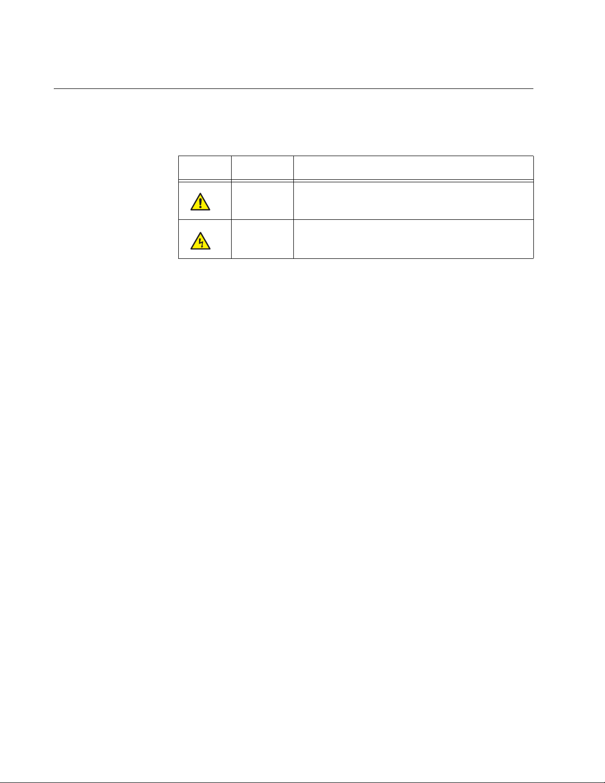
This document uses the safety symbols defined in Table 1.
Table 1. Safety Symbols
Symbol Meaning Description
Caution Performing or omitting a specific action may
result in equipment damage or loss of data.
Warning Performing or omitting a specific action may
result in electrical shock.
12
Page 13

Where to Find Web-based Guides
The installation and user guides for all Allied Telesis products are available
in portable document form (PDF) on our web site.
AT-FS750/24POE Fast Ethernet WebSmart Switch Installation Guide
Go to http://www.alliedtelesis.com/support/software
model number of your product in the “Search by Product” field. You can
view the documents online or download them onto a local workstation or
server.
and enter the
13
Page 14

Preface
Contacting Allied Telesis
This section provides Allied Telesis contact information for technical
support as well as sales or corporate information.
Online Support You can request technical support online by accessing the Allied Telesis
Knowledge Base from the following web site:
www.alliedtelesis.com/support. You can use the Knowledge Base to
submit questions to our technical support staff and review answers to
previously asked questions.
Email and
Telephone
Support
For Technical Support via email or telephone, refer to the Allied Telesis
web site: www.alliedtelesis.com. Select your country from the list
displayed on the website. Then select the appropriate menu tab.
Warranty For the AT-FS750/24POE Fast Ethernet WebSmart Switch hardware
warranty information, refer to the Allied Telesis web site at
www.alliedtelesis.com/warranty.
Returning
Products
For Sales or
Corporate
Products for return or repair must first be assigned a Return Materials
Authorization (RMA) number. A product sent to Allied Telesis without a
RMA number will be returned to the sender at the sender’s expense. For
instructions on how to obtain an RMA number, go to the Support section
on our web site at www.alliedtelesis.com.
You can contact Allied Telesis for sales or corporate information at our
web site: www.alliedtelesis.com. Select your country from the list
displayed on the website. Then select the appropriate menu tab.
Information
14
Page 15

Management Software Updates
New releases of management software for our managed products are
available from either of the following Internet sites:
Allied Telesis web site: www.alliedtelesis.com
Allied Telesis FTP server: ftp://ftp.alliedtelesis.com
If you prefer to download new software from the Allied Telesis FTP server
from your workstation’s command prompt, you will need FTP client
software and you must log in to the server. Enter “anonymous” for the user
name and your email address for the password.
AT-FS750/24POE Fast Ethernet WebSmart Switch Installation Guide
15
Page 16

Preface
16
Page 17

Chapter 1
Overview
The AT-FS750/24POE Fast Ethernet WebSmart Switch is designed to
simplify the task of creating or expanding an Ethernet or Fast Ethernet
network.
This chapter contains the follows sections:
“Features” on page 18
“Front and Back Panels” on page 19
“Ports” on page 20
“Eco-friendly Switch” on page 21
“LEDs” on page 22
“Power Supply” on page 26
“Power over Ethernet” on page 27
“Ethernet Switching Basics” on page 29
17
Page 18

Chapter 1: Overview
Features
The features of the AT-FS750/24POE Fast Ethernet WebSmart Switch
include:
24 Auto-Negotiating 10/100Base-T twisted pair ports with RJ-45
connectors
Two uplink combo ports that consist of two 10/100/1000Base-T twisted
pair ports and two Gigabit small form-factor pluggable (SFP) ports
Store and Forward switching supports line rates of:
– 1,480,000 pps (1000 MB/sec)
– 148,000 pps (100 MB/sec)
– 14,800 pps (10 MB/sec)
Non-Blocking Full-Wire speed switching on all packet sizes
MAC address table capacity of up to 8K addresses with automatic
aging
IEEE 802, IEEE 802.3u, and IEEE802.3z
IEEE 802.3af POE compliant on ports 1 - 12 (Alternative A)
IEEE 802.3 and IEEE 802.3u compliant
IEEE 802.3x supports”
– Flow Control in full-duplex operation
– Back Pressure in half-duplex operation
– Auto MDI/MDI-X on all twisted pair ports
(including combo ports)
Eco-friendly switch for enabling/disabling port LEDs and for resetting
switch
Minimizes transmit signal power on each GE port based on the
specific cable length to the end point
Each port assumes low power mode when link goes down
Installation on desktop, mounted on the wall, and mounted in a 19”
rack.
Smart Fan with fan speed control, device acoustic noise less than
40dB
Front panel LEDs for unit and port status
Web-based configuration using the AT-S105 Management software
18
Page 19
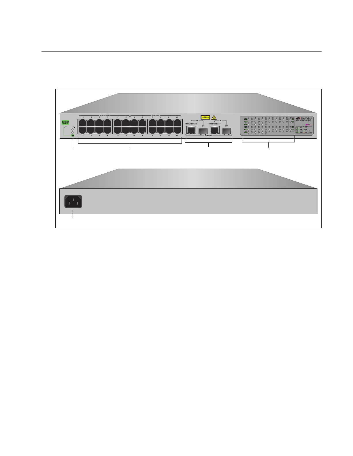
Front and Back Panels
10/100Base Twisted Pair Ports
Port LEDs
Uplink Combo Ports
System LEDs
eco-friendly Switch
AC Power
Figure 1 illustrates the front and back panels of the AT-FS750/24POE Fast
Ethernet WebSmart Switch.
SYSTEM
POWER
POE
AT-FS750/24POE Fast Ethernet WebSmart Switch Installation Guide
24 Port 10/100 Mbps WebSmart Switch
with 12 POE and 2 Combo SFP Ports
1714
50-60Hz
100-240VAC~
1715
Figure 1. AT-FS750/24POE Front and Back Panels
19
Page 20

Chapter 1: Overview
Note
Ports
The AT-FS750/24POE Fast Ethernet WebSmart Switch features 24
twisted pair ports and two uplink combo ports. See the following sections
for more information:
“Twisted Pair Ports”
“Uplink Combo Ports”
Twisted Pair
Ports
The ports on the AT-FS750/24POE Fast Ethernet WebSmart Switch are
are capable of 10 megabits per second (Mbps) and 100 Mbps speeds and
are 10Base-T and 100Base-TX compliant.The twisted pair ports feature 8pin RJ-45 connectors. (For the port pinouts, refer to “Connectors and Port
Pinouts” on page 57.)
The ports are IEEE 802.3u Auto-Negotiation compliant. With AutoNegotiation, the switch automatically matches the highest possible
common speed between each switch port and each end node. For
example, if an end node is capable of only 10 Mbps, the switch sets the
port connected to the end node to 10 Mbps.
Each twisted pair port on the switch can operate in either half- or fullduplex mode. The twisted pair ports are IEEE 802.3u-compliant and AutoNegotiate the duplex mode setting.
For the switch to set the duplex mode for each port correctly, the
end nodes that you connect to the switch ports must be configured
for Auto-Negotiation. Otherwise, a duplex mode mismatch can
occur, affecting network performance. For further information, refer
to “Duplex Mode” on page 30.
Uplink Combo
Ports
Each twisted pair port has a maximum operating distance of 100 m
(328 feet). For 10 Mbps operation, Category 3 or better 100 ohm shielded
or unshielded twisted pair cabling is required. For 100 or 1000 Mbps
operation, Category 5 and Enhanced Category 5 (5E) 100 ohm shielded
or unshielded twisted pair cabling is required.
The twisted pair ports are auto-MDI. They automatically configure
themselves as either MDI or MDI-X, which allows you to use straight
through or crossover twisted pair cables to connect devices to the ports.
The two uplink combo ports (ports 49 and 50) consist of an SFP port and a
redundant twisted-pair port. The SFP ports support fiber optic connectivity
at 100FX and 1000 SX/LX, while the twisted pair ports support 10/100/
1000Base-T. If both ports of a combo pair are connected to the network,
traffic is switched through the SFP port and the corresponding twisted pair
port acts a redundant port in case of failure.
20
Page 21

Eco-friendly Switch
POWER
POE
SYSTEM
The eco-friendly switch on the front panel is multifunctional and shown in
Figure 2. It may be used to conserve power by turning off the port/POE
LEDs, reset the switch, or reset the switch configuration to the factory
default settings. The switch functions are described in Table 2.
AT-FS750/24POE Fast Ethernet WebSmart Switch Installation Guide
1716
Figure 2. Eco-friendly Switch
Table 2. Eco-friendly Switch Functions
Action Results
Momentarily press the
switch.
Enable or disable all front panel LEDs with the
exception of the POWER LED which remains
active at all times.
Hold the switch down for
Reset the switch.
more than 5 seconds, but
less than 10 seconds.
Hold the switch down for
more than 10 seconds.
Reset the switch and reset the configuration to
the factory default settings.
21
Page 22

Chapter 1: Overview
POWER
POE
SYSTEM
LEDs
The AT-FS750/24POE Fast Ethernet WebSmart Switch provides the
following LEDs:
“System LEDs” on page 22
“10/100Base-T POE Port LEDs” on page 23
“10/100Base-T Non-POE Port LEDs” on page 24
“Uplink Combo Port LEDs” on page 25
System LEDs The switch has two system-level LEDs, Power and POE, as shown in and
described in Table 3.
1716
Figure 3. System LEDs
Table 3. System LEDs
LED State Description
Solid Green The switch is powered up and operating normally.
Power
Blinking Green The switch is starting up, performing a self-test, or
downloading software.
Off The switch is powered off.
POE Solid Green Power is available for the POE ports.
Solid Amber POE failed.
22
Page 23

AT-FS750/24POE Fast Ethernet WebSmart Switch Installation Guide
10/100Base-T
POE Port LEDs
Ports 1 through 12 each have three LEDs as shown in Figure 4 and
described in Table 4.
.
Figure 4. POE Port LEDs (Port 1 - 12)
Table 4. 10/100Base-T POE Port LEDs (Ports 1 - 12)
LED State Description
Solid Green A valid link has been established on the
port.
L/A
Blinking
Green
The port is transmitting or receiving data.
100M
PoE
Off No link is established on the port.
Solid Green A valid 100 Mbps link is established
between the uplink port and the end node.
Off A valid 10 Mbps link is established between
the port and the end node.
Solid Green The port detects a Powered Device and
complies with the condition of the normal
load.
Blinking
Green
Off No PoE power feeding a Powered Device.
Indicates an overload or a short of a terminal
port or external forced voltage feeds into the
port.
23
Page 24

Chapter 1: Overview
10/100Base-T
Non-POE Port
LEDs
Ports 13 through 24 each have two LEDs as shown in Figure 5 and
described in Table 5.
.
Figure 5. 10/100Base-T Non-PoE Port LEDs (Port 13 - 24)
Table 5. 10/100Base-T Non-PoE Port LEDs (Port 13 - 24) Description
LED State Description
Solid Green A valid 10/100M link has been established.
L/A
100M
Blinking
Green
Off No link is established on the port.
Solid Green A valid 100 Mbps link is established between
Off A valid 10 Mbps link is established between
The port is transmitting or receiving data.
the port and the end node.
the port and the end node.
24
Page 25

AT-FS750/24POE Fast Ethernet WebSmart Switch Installation Guide
Uplink Combo
Port LEDs
The LEDs for the uplink combo ports, ports 25 and 26, are shown in
Figure 6 and described in Table 6.
Figure 6. Uplink Combo Port LEDs
Table 6. Uplink Combo Port LEDs Description
LED State Description
Solid Green A valid link has been established on the port.
L/A
SPD
Blinking
Green
Off No link is established on the port.
Solid Green A valid 1000 Mbps link is established
Solid Amber A valid 100 Mbps link is established between
Off A valid 10 Mbps link is established between
The port is transmitting or receiving data.
between the uplink port and the end node.
the uplink port and the end node.
the uplink port and the end node.
25
Page 26

Chapter 1: Overview
Note
Power Supply
The switch has an internal power supply with a single AC power supply
socket on the back panel. To power the switch on or off, connect or
disconnect the power cord provided with the switch.
For the power requirements, refer to “Power Specifications” on
page 55.
26
Page 27

Power over Ethernet
Note
The twisted pair ports on the AT-FS750/24POE Fast Ethernet WebSmart
Switch feature Power over Ethernet (PoE). PoE is a mechanism for
supplying power to network devices over the same twisted pair cables
used to carry network traffic. This feature can simplify network installation
and maintenance by allowing you to use the switch as a central power
source for other network devices.
A device that receives its power over an Ethernet cable is called a
powered device. Examples of such devices are wireless access points, IP
telephones, webcams, and even other Ethernet switches. A powered
device connected to a port on the switch receives both network traffic and
power over the same twisted pair cable.
The switch automatically determines whether a device connected to a port
is a powered device or not. A powered device has a signature resistor or
signature capacitor that the switch can detect over the Ethernet cabling. If
the resistor or capacitor is present, the switch assumes that the device is a
powered device.
AT-FS750/24POE Fast Ethernet WebSmart Switch Installation Guide
Power Budgeting The AT-FS750/24POE Fast Ethernet WebSmart Switch is capable of
providing a maximum of 15.4 W of power per port on six of the twelve POE
ports for a total power consumption of 100 W, while at the same time
furnishing standard 10/100 Mbps Ethernet functionality.
The AT-FS750/24POE smart power management functionality supports
any combination of the first twelve Ethernet ports (1-12) that supply power
for IEEE 802.3af Class 0, 1, 2, or 3 powered devices up to a maximum of
100 watts, as described in Table 7 on page 28.
Power is supplied to the powered devices in the order that the ports
are connected or on a first-come-first-served basis until the 100 watt
limit is reached. If the switch is power cycled after the PoE devices
are connected to the switch ports, the power is supplied to ports 1
through 12 in that order. Refer to “Power Specifications” on page 55
for more information on available power.
27
Page 28

Chapter 1: Overview
Table 7. IEEE 802.3af Class vs. Power Levels
Class Usage
Minimum Power
Levels Output at
the PSE
Maximum Power
Levels Output at
the PD
0 Default 15.4W 0.44W to 12.95W
1 Optional 4.0W 0.44W to 3.84W
2 Optional 7.0W 3.84W to 6.49W
3 Optional 15.4W 6.49W to 12.95W
A port connected to a network node that is not a powered device (that is, a
device that receives its power from another power source) functions as a
regular Ethernet port, without PoE. The PoE feature remains enabled on
the port but no power is delivered to the device.
Implementation A standard Ethernet twisted pair cable contains four pairs of strands for a
total of eight strands. Network traffic at speeds of 10/100 Mbps requires
only four strands (1, 2, 3, and 6), leaving four strands in the cable unused
(4, 5, 7, and 8).
The PoE standard, IEEE 802.3af, describes two alternative ways for
delivering power to a powered device (PD) over twisted pair cabling.
Alternative A uses the same strands that carry the network traffic
where Alternative B uses the spare strands of the cable. The PoE
implementation on the AT-FS750/24POE Fast Ethernet WebSmart Switch
is Alternative A, where power is transmitted over strands 1, 2, 3, and 6.
PDs that comply with the IEEE 802.3af standard typically support both
power delivery methods. So long as a PD is compliant with the standard, it
receives its power from the switch while using either a straight or crossover cable. The PoE feature on the AT-FS750/24POE Fast Ethernet
WebSmart Switch works with most legacy PDs as long as the device can
be powered on pins 1, 2, 3, and 6. A legacy device is a node that was
manufactured before the IEEE 802.3af standard was completed and,
consequently, may not adhere to the standard. If this is the case, a straight
(MDI) cable may be needed to insure that the DC polarity is correct.
28
Page 29

Ethernet Switching Basics
An Ethernet switch interconnects network devices, such as workstations,
printers, routers, and other Ethernet switches, so that they can
communicate with each other by sending and receiving Ethernet frames.
AT-FS750/24POE Fast Ethernet WebSmart Switch Installation Guide
MAC Address
Table
Every hardware device on your network has a unique MAC address. This
address is assigned to the device by the device’s manufacturer. For
example, when you install a Network Interface Card (NIC) in a computer
so that you can connect it to the network, the NIC already has a MAC
address assigned to it by its manufacturer.
The MAC address table in the AT-FS750/24POE Fast Ethernet WebSmart
Switch can store up to 8K MAC addresses. The switch uses the table to
store the MAC addresses of the network end nodes connected to the
ports, along with the port number on which each address was learned.
A switch learns the MAC addresses of the end nodes by examining the
source address of each packet received on a port and adding. It adds the
address and port on which the packet was received into the MAC table if
the address does not already exist. The result is a table that contains all
the MAC addresses of the network devices connected to the switch’s
ports, and the port number where each address was learned.
When the switch receives a packet, it also examines the destination
address and, by referring to its MAC address table, determines the port on
which the destination end node is connected. Then it forwards the packet
to the appropriate port and on to the end node. This increases network
bandwidth by limiting each frame to the appropriate port when the
intended end node is located, freeing the other switch ports for receiving
and transmitting data.
If the switch receives a packet with a destination address that is not in the
MAC address table, it floods the packet to all of the ports on the switch. If
the ports have been grouped into virtual LANs, the switch floods the
packet only to those ports which belong to the same VLAN as the port on
which the packet was received. This prevents packets from being
forwarded into inappropriate LAN segments, decreasing network security.
When the destination end node responds, the switch adds its MAC
address and port number to the table.
If the switch receives a packet with a destination address that is on the
same port on which the packet was received, it discards the packet without
forwarding it on to any port. Since both the source end node and the
destination end node for the packet are located on the same port on the
switch, there is no reason for the switch to forward the packet.
29
Page 30

Chapter 1: Overview
Duplex Mode Duplex mode refers to how an end node receives and transmits data. If an
end node can receive or transmit data, but not both simultaneously, it is
operating in what is referred to as half-duplex mode. If an end node can
both receive and transmit data simultaneously, the end node is operating
in full-duplex mode. Naturally, an end node capable of operating in fullduplex can handle data much faster than an end node that can only
operate in half-duplex mode.
The twisted pair ports on the AT-FS750/24POE Fast Ethernet WebSmart
Switch can operate in either half-or full-duplex mode. They are IEEE
802.3u-compliant and you can set them to Auto-Negotiation.
For Auto-Negotiation to operate properly on a switch, the end nodes
connected to the switch should also use Auto-Negotiation. If an end node
does not have this feature and has a fixed duplex mode of full-duplex, the
result is a duplex mode mismatch between the end node and a switch
port. A port on the Fast Ethernet switch connected to an end node with a
fixed duplex mode of full-duplex operates at only half-duplex. This results
in the end node using full-duplex and the switch port using half-duplex.
This can produce network performance problems. If you encounter this
situation, you must configure the port on the end node to use AutoNegotiation or, if it lacks that feature, to half-duplex.
Store and
Forward
Back Pressure
and Flow Control
The switch uses store and forward as the method for receiving and
transmitting frames. When a Ethernet frame is received on a switch port,
the switch does not retransmit the frame out the destination port until it has
received the entire frame and stored the frame in a port buffer. It then
examines the frame to determine if it is a valid frame. Invalid frames, such
as fragments or runts, are discarded by the switch. This ensures that only
valid frames are transmitted out the switch ports and that damaged frames
are not propagated on your network.
To maintain the orderly movement of data between the end nodes, an
Ethernet switch may periodically need to signal an end node to stop
sending data. This can occur under several circumstances. For example, if
two end nodes are operating at different speeds, the switch, while
transferring data between the end nodes, might need to instruct the faster
end node to stop transmitting data to allow the slower end node to catch
up. An example of this would be when a server operating at 100 Mbps is
sending data to a workstation operating at only 10 Mbps.
How a switch signals an end node to stop transmitting data differs
depending on the speed and duplex mode of the end node and switch
port. A twisted pair port operating at 100 Mbps and half-duplex mode
stops an end node from transmitting data by forcing a collision. A collision
on an Ethernet network occurs when two end nodes attempt to transmit
data using the same data link at the same time. A collision causes end
nodes to stop sending data. When the switch needs to stop a 100 Mbps,
half-duplex end node from transmitting data, it forces a collision on the
30
Page 31

AT-FS750/24POE Fast Ethernet WebSmart Switch Installation Guide
data link, which stops the end node. When the switch is ready to receive
data again, the switch stops forcing collisions. This is referred to as back
pressure.
A port operating at 100 Mbps and full-duplex mode uses PAUSE frames,
as specified in the IEEE 802.3x standard, to stop the transmission of data
from an end node. Whenever the switch wants an end node to stop
transmitting data, it issues this frame. The frame instructs the end node to
cease transmission. The switch continues to issue PAUSE frames until it is
ready again to receive data from the end node. This is referred to as flow
control.
The AT-FS750/24POE Fast Ethernet WebSmart Switch supports both
transmit (TX) and receive (RX) flow control.
31
Page 32

Chapter 1: Overview
32
Page 33

Chapter 2
Installation
This chapter describes how to install the AT-FS750/24POE Fast Ethernet
WebSmart Switch on a desktop, on a wall, or in a rack. In addition, a
description of how to start a management session with the AT-S105
management software is provided. This chapter contains the following
sections:
“Reviewing Safety Precautions” on page 34
“Selecting a Site for the Switch” on page 37
“Cable Specifications” on page 38
“Unpacking the Switch” on page 39
“Installing the Switch on a Desktop” on page 40
“Installing the Switch on a Wall” on page 41
“Installing a Switch in a Rack” on page 44
“Installing an SFP Transceiver” on page 46
“Cabling and Powering On the Switch” on page 48
“Starting a Management Session” on page 52
33
Page 34

Chapter 2: Installation
Note
Reviewing Safety Precautions
Please review the following safety precautions before you begin to install
the switch.
The indicates that a translation of the safety statement is
available on the Allied Telesis website.
Go to http://www.alliedtelesis.com/support/software
“Switches” under Product Category and this product under Product
Name. You can view this document online or download it onto a
local workstation or server.
Warning: Class 1 Laser product.
Warning: Do not stare into the laser beam.
Warning: To prevent electric shock, do not remove the cover.
No user-serviceable parts inside. This unit contains hazardous
voltages and should only be opened by a trained and qualified
technician. To avoid the possibility of electric shock, disconnect
electric power to the product before connecting or disconnecting
the LAN cables.
Warning: Do not work on equipment or cables during periods of
lightning activity.
Warning: Power cord is used as a disconnection device. To deenergize equipment, disconnect the power cord.
E1
E2
L1
L2
. Select
E3
Warning: Class I Equipment. This equipment must be earthed.
The power plug must be connected to a properly wired earth
ground socket outlet. An improperly wired socket outlet could
place hazardous voltages on accessible metal parts.
Pluggable Equipment. The socket outlet shall be installed near
the equipment and shall be easily accessible.
Caution: Air vents must not be blocked and must have free
access to the room ambient air for cooling.
E6
E5
E4
34
Page 35

AT-FS750/24POE Fast Ethernet WebSmart Switch Installation Guide
Warning: Operating Temperature. This product is designed for a
maximum ambient temperature of 40° degrees C.
All Countries: Install product in accordance with local and
National Electrical Codes.
Warning: As a safety precaution, install a circuit breaker with a
minimum value of 15 Amps between the equipment and the DC
power source.
Always connect the wires to the LAN equipment first before you
connect the wires to the circuit breaker. Do not work with HOT
feeds to avoid the danger of physical injury from electrical shock.
Always be sure that the circuit breaker is in the OFF position
before connecting the wires to the breaker.
Caution: The attached mounting brackets must be used to
securely mount the device on the wall.
E8
E15
E9
E7
Circuit Overloading: Consideration should be given to the
connection of the equipment to the supply circuit and the effect
that overloading of circuits might have on over current protection
and supply wiring. Appropriate consideration of equipment
nameplate ratings should be used when addressing this
concern.
Warning: Mounting of the equipment in the rack should be such
that a hazardous condition is not created due to uneven
mechanical loading.
If installed in a closed or multi-unit rack assembly, the operating
ambient temperature of the rack environment may be greater
than the room ambient temperature. Therefore, consideration
should be given to installing the equipment in an environment
compatible with the manufacturer’s maximum rated ambient
temperature (Tmra).
Caution: Installation of the equipment in a rack should be such
that the amount of air flow required for safe operation of the
equipment is not compromised.
E21
E25
E35
E36
Warning: Reliable earthing of rack-mounted equipment should
be maintained. Particular attention should be given to supply
connections other than direct connections to the branch circuits
(e.g., use of power strips).
E37
35
Page 36

Chapter 2: Installation
Warning: To reduce the risk of electric shock, the PoE ports on
this product must not connect to cabling that is routed outside
the building where this device is located.
E40
36
Page 37

Selecting a Site for the Switch
Observe the following requirements when choosing a site for your switch:
If you plan to install the switch in an equipment rack, ensure that the
rack is safely secured and that it will not tip over. Devices in a rack
should be installed starting at the bottom, with the heavier devices
near the bottom of the rack.
If you are installing the switch on a table, ensure that the table is level
and secure.
The power outlet for the switch should be located near the unit and
should be easily accessible.
The site should provide for easy access to the ports on the front of the
switch. This makes it easy for you to connect and disconnect cables,
as well as view the switch’s LEDs.
To allow proper cooling of the switch, air flow around the unit and
through its vents on the side and rear should not be restricted.
AT-FS750/24POE Fast Ethernet WebSmart Switch Installation Guide
Do not place objects on top of the switch.
Do not expose the switch to moisture or water.
Ensure that the site is a dust-free environment.
Use dedicated power circuits or power conditioners to supply reliable
electrical power to the network devices.
37
Page 38

Chapter 2: Installation
Note
Cable Specifications
Twisted Pair
Ports
Speed Type of Cable
10 Mbps Category 3 or better 100-ohm shielded or
100 Mbps Category 5 or Category 5E (Enhanced) 100-
1000 Mbps Category 5 and Category 5E (Enhanced) 100-
Table 8 contains the cabling specifications for the twisted pair ports.
Table 8. Twisted Pair Cabling and Distances
Maximum
Operating
Distance
100 m (328 ft)
unshielded twisted pair cable
100 m (328 ft)
ohm shielded or unshielded twisted pair cable
100 m (328 ft)
ohm shielded or unshielded twisted pair cable
The twisted pair ports on the switch feature auto-MDI when
operating at 10, 100 or 1000 Mbps. Each port is individually
configured as MDI or MDI-X when connected to an end node.
Consequently, you can use either a straight-through or crossover
twisted pair cable when connecting any network device to a twisted
pair port on the switch.
SFP Ports Refer to the specific Allied Telesis SFP data sheet for the cable
specifications for the your installation.
38
Page 39

Unpacking the Switch
Note
To unpack the switch, perform the following procedure:
1. Remove all components from the shipping package.
2. Place the switch on a level, secure surface.
3. Ensure that the following hardware components are included in your
AT-FS750/24POE Fast Ethernet WebSmart Switch Installation Guide
Store the packaging material in a safe location. You must use the
original shipping material if you need to return the unit to Allied
Telesis.
switch package. If any item is missing or damaged, contact your Allied
Telesis sales representative for assistance.
One AT-FS750/24POE WebSmart Fast Ethernet Switch and the
following:
Mounting brackets - 2 pieces (1set)
Rack mounting screws - 8 pieces (for bracket to device)
Rack Mounting screws - 4 pieces (for bracket to rack)
Wall mounting anchors - 4 pieces
Wall mounting screws - 4 pieces
Rubber feet - 4 pieces
One power cord
39
Page 40

Chapter 2: Installation
Installing the Switch on a Desktop
To install the switch on a desktop, perform the following procedure:
1. Remove all equipment from the package and store the packaging
material in a safe place.
2. Turn the switch over and attach the four rubber feet to the bottom of
the switch as shown in Figure 7.
with 12 POE and 2 Combo SFP Ports
24 Port 10/100 Mbps WebSmart Switch
POE
POWER
SYSTEM
1720
Figure 7. Attaching the Rubber Feet
3. Turn the switch over again and place it on a flat, secure surface (such
as a desk or table) leaving ample space around the unit for ventilation.
4. If you plan to install SFP transceiver modules, go to the next step at
“Installing an SFP Transceiver” on page 46. Otherwise, your next step
is “Cabling and Powering On the Switch” on page 48.
40
Page 41

Installing the Switch on a Wall
Note
The AT-FS750/24POE WebSmart Fast Ethernet Switch can be mounted
vertically on a wall using the two mounting brackets, screws, and anchors
provided in the accessory kit.
Store the packaging material in a safe location. You must use the
original shipping material if you need to return the unit to Allied
Telesis.
To wall-mount the switch, perform the following procedure:
1. Place the unit on a level, secure surface.
2. Attach a mounting bracket to one side of the switch using four Phillips
head screws that come with the switch, as shown in Figure 8.
AT-FS750/24POE Fast Ethernet WebSmart Switch Installation Guide
24 Po
r
t 10/100 Mbps WebSmar
with 12 POE and 2 Combo SFP P
t Sw
itc
h
o
r
ts
1759
Figure 8. Attaching Brackets for Wall Mounting
3. Install the second mounting bracket on the other side of the switch
using the four remaining Phillips head screws.
41
Page 42

Chapter 2: Installation
4. Install four plastic anchors into the wall.
Drill holes in the wall so that they are level with each other and spaced
as shown in Figure 9.
Each hole must be 0.635 mm (0.25 in) in diameter.
465mm (18.3in)
31.75 (1.25in)
0.635mm DIA
(0.25in)
Figure 9. Positioning and Drilling Holes for Wall Installation
42
Page 43

AT-FS750/24POE Fast Ethernet WebSmart Switch Installation Guide
5. Position the switch on the wall and fasten with four screws, as
illustrated in Figure 10 on page 43.
P
O
P
OW
E
E
S
R
Y
S
T
E
M
with 12 POE and 2 C
24
P
o
r
t 10/100 Mbps
om
bo SFP P
WebSm
a
o
r
t Switch
r
ts
1760
Figure 10. Positioning the Switch onto the Wall with Mounting Screws
6. If you plan to install SFP transceiver modules, go to “Installing an SFP
Transceiver” on page 46. Otherwise, your next step is “Cabling and
Powering On the Switch” on page 48.
43
Page 44

Chapter 2: Installation
Installing a Switch in a Rack
To install the switch in a rack, perform the following procedure:
1. If attached, remove the rubber feet using a flat-head screwdriver as
shown in Figure 11.
Figure 11. Removing Feet from Switch
2. Install a bracket on one side of the switch using a Phillips screwdriver
and three of the rack-mount screws included with the switch. Figure 12
shows how to mount the brackets on the switch.
24 Po
r
t 10
/100 M
w
ith 12 P
bps
WebSm
O
E
and 2 C
a
r
t S
om
w
itch
bo SFP
P
o
r
ts
1720
Figure 12. Attaching the Rack-Mount Bracket
3. Repeat step 2 to attach the remaining bracket to the other side of the
switch.
44
Page 45

AT-FS750/24POE Fast Ethernet WebSmart Switch Installation Guide
Note
4. Mount the switch on a 19-inch rack, as shown in Figure 13.
The rack mount screws are not provided.
24 Port 10/100 M
w
ith
12 POE
b
ps
WebSm
and 2 Co
a
r
t Switch
m
bo SFP
P
orts
1721
Figure 13. Mounting the Switch on the Rack
5. If you plan to install SFP transceiver modules, go to the next step at
“Installing an SFP Transceiver” on page 46. Otherwise, your next step
will be “Cabling and Powering On the Switch” on page 48.
45
Page 46

Chapter 2: Installation
Note
Note
Installing an SFP Transceiver
The AT-FS750/24POE WebSmart Fast Ethernet Switchhas four SFP
combo ports. Perform this procedure before “Cabling and Powering On
the Switch” on page 48.
To install an SFP transceiver, perform the following procedure:
The transceiver can be hot-swapped; you do not need to power off
the switch to install an SFP transceiver. However, always remove
the cables before removing the transceiver.
You must install an SFP transceiver before you connect cables to it.
1. Remove the transceiver from its shipping container and store the
packaging material in a safe location.
2. Remove the dust plug from the SFP slot, as shown in Figure 14.
1722
Figure 14. Removing the Dust Plug from the SFP Slot
3. Locate the label on the transceiver and turn it so that the label is on top
and the alignment groove is on the bottom.
46
Page 47

AT-FS750/24POE Fast Ethernet WebSmart Switch Installation Guide
Note
Note
4. Slide the SFP transceiver into an SFP slot on the switch, as shown in
Figure 15.
1723
Figure 15. Inserting the SFP
5. Repeat steps 2 through 4 if you are installing a second SFP
transceiver.
SFP transceivers are dust sensitive. When a fiber optic cable is not
installed, or when you store the SFP, always keep the plug in the
optical bores. When you do remove the plug, keep it for future use.
Refer to “Cleaning Fiber Optic Connectors” on page 59 if fiber
connections require cleaning
Unnecessary removal and insertion of an SFP transceiver can lead
to premature failure.
For information about cabling for the SFP, consult the documentation
that was shipped with the SFP.
47
Page 48

Chapter 2: Installation
Note
Cabling and Powering On the Switch
Connecting the
Twisted Pair
Cables
To connect the twisted cables to the RJ-45 ports on the AT-FS750/24POE
WebSmart Fast Ethernet Switch, perform the following procedure:
If you plan to configure a redundant data path, make sure that the
Spanning Tree feature is enabled via the AT-S105 Management
Software before connecting the ethernet cables for your secondary
network connections.
1. Plug the twisted pair data cables to the RJ-45 ports on the switch, as
shown in Figure 16.
1726
Figure 16. Connecting the Twisted Pair Data Cables
When connecting a twisted pair cable to a port, observe the following
guidelines:
An RJ-45 connector should fit snugly into the port on the switch.
The tab on the connector should lock the connector into place.
The ports on the switch are auto-MDI/MDI-X. You can use either a
straight-through or crossover twisted pair cable to connect any
type of network device to a port on the switch.
The network should not contain data loops, which can adversely
affect network performance. A data loop exists when two or more
network devices can communicate with each other over more than
one data path.
48
Page 49

AT-FS750/24POE Fast Ethernet WebSmart Switch Installation Guide
Note
.
Warning: To reduce the risk of electric shock, the PoE ports on
this product must not connect to cabling that is routed outside
the building where this device is located.
2. Connect the other end of the twisted pair cable to a port in the end
node.
E40
Connecting the
Fiber Optic
Cables
To connect a fiber optic cable to an SFP transceiver installed in the
AT-FS750/24POE WebSmart Fast Ethernet Switch, perform the following
procedure:
If you plan to configure a redundant data path, make sure that the
Spanning Tree feature is enabled via the AT-S105 Management
Software before connecting the ethernet cables for your secondary
network connections.
1. Remove the dust plug from the SFP transceiver, as shown in
Figure 17.
1724
Figure 17. Removing the Dust Plug from the SFP transceiver
49
Page 50

Chapter 2: Installation
2. Connect the fiber optic cable to the SFP port, as shown in Figure 18.
1725
Powering On the
Switch
Figure 18. Connecting the Fiber Optic Cable
To power on the switch, perform the following procedure:
1. Plug the power cord into the AC power connector on the back of the
switch, as shown in Figure 19.
50-60Hz
100-240VAC~
1727
Figure 19. Plugging in the AC Power Cord
2. Plug the other end of the power cord into a wall outlet.
Warning: Power cord is used as a disconnection device. To deenergize equipment, disconnect the power cord.
E3
50
Page 51

AT-FS750/24POE Fast Ethernet WebSmart Switch Installation Guide
Note
Pluggable Equipment. The socket outlet shall be installed near
the equipment and shall be easily accessible.
E5
3. Verify that the POWER LED is green. If the LED is OFF, refer to
Chapter 3, “Troubleshooting” on page 53.
The switch is now powered on and ready for network operations. To
start a local management session on the switch, refer to “Starting a
Management Session” on page 52. For more information about
staring a remote management session, see the AT-S105
Management Software User’s Guide.
51
Page 52

Chapter 2: Installation
Starting a Management Session
To start a management session on an AT-FS750/24POE WebSmart Fast
Ethernet Switch, perform the following procedure:
1. In a web browser address box, enter the following IP address:
192.168.1.1
The main page for the AT-S105 management software is shown in
Figure 20.
Figure 20. AT-S105 Management Software Main Page
Because the switch initially has no login or password protection, follow
the instructions in the AT-S105 Management Software User’s Guide to
change the IP address and add administrative users.
52
Page 53

Chapter 3
Note
Troubleshooting
This chapter contains information on how to troubleshoot the switch in the
event that a problem occurs.
If you need further assistance, please contact Allied Telesis
Technical Support. Refer to “Contacting Allied Telesis” on page 14.
POWER LED is OFF
Check the POWER LED on the front of the switch. If the LED is off,
indicating that the unit is not receiving power, do the following:
Ensure that the power cord is securely connected to the power source
and to the AC connector on the back panel of the switch.
Verify that the power outlet has power by connecting another device
to it.
Try connecting the unit to another power source.
Try using a different power cord.
Verify that the voltage from the power source is within the required
levels for your region.
LINK/ACT LED is OFF
Verify that the LINK/ACT LED for each port is ON. If a LINK/ACT LED is
OFF, do the following:
Verify that the end node connected to the port is powered on and is
operating properly.
Verify that the twisted pair cable is securely connected to the port on
the switch and to the port on the end node.
Ensure that the twisted pair cable does not exceed 100 meters (328
feet).
Verify that you are using the appropriate category of twisted pair
cable:
– Category 3 or better for 10 Mbps operation
– Category 5 and Category 5E for 100 and 1000
Mbps operation.
53
Page 54

Chapter 3: Troubleshooting
Note
A 1000Base connection may require five to ten seconds to establish
a link.
POE LED is not Green - Powered Device is not Receiving Power
If you attached a powered device (PD) to a port on a AT-FS750/24POE,
the PoE LED for the port should be green. If the device is not receiving
power or the PoE LED is flashing amber, steady amber, or is OFF, do the
following:
Check to be sure that the PD is designed to receive power over pins 1,
2, 3, and 6 on the RJ-45 port. This can be verified by reviewing the
device’s documentation or data sheet.
Check that the device’s power requirements do not exceed 15.4 W.
This can be verified by reviewing the device’s documentation or data
sheet.
Verify that the PD is not faulty
Verify that you are using the appropriate category of twisted pair cable:
Category 3 or better for 10 Mbps operation, Category 5/5E for 100
Mbps operations.
Verify that the twisted pair cable is not faulty by replacing it with a
known good cable.
Use the CLI management software to determine whether PoE is
enabled on the switch and the port. The default setting for PoE is
enabled.
Use the management software to determine whether the PoE power
setting for the port has been reduced from the default setting of
15.4 W, to a value below the power requirements of the device.
Verify that the power budget on the switch is not being exceeded by
the number of PDs and their load requirements. Refer to “IEEE
802.3af Class vs. Power Levels” on page 28 for the maximum power
supported for each Class.
54
Page 55

Appendix A
Technical Specifications
Physical Specifications
Dimensions (W x D x H): 440 mm x 257 mm x 43.2 mm
Weight: 4.133 kg (9.11 lbs)
Environmental Specifications
Operating Temperature: -0° C to 40° C (14° F to 122° F)
(17.32 in x 10.12 in x 1.70 in)
Storage Temperature: -25° C to 70° C (-40° F to 158° F)
Operating Humidity: 5% to 90% non-condensing
Storage Humidity: 5% to 95% non-condensing
Operating Altitude Range: Up to 3,000 m (9,843 ft)
Power Specifications
AC Voltage/Frequency Requirements: 100 - 240 VAC, 50/60 Hz
AC Input Power Consumption: 130 W Maximum
Available Power over Ethernet: 100 W @ 48 VDC
IEEE 802.3af Class 3 (15.4 W): Max 6 ports
IEEE 802.3af Class 2 (7.3 W): Max 12 ports
IEEE 802.3af Mode: Alternative A (MDI)
55
Page 56

Appendix A: Technical Specifications
Safety and Electromagnetic Emissions Certifications
EMI/RFI: FCC Class A, EN55022 Class A,
CISPR Class A
Immunity: EN55024
Electrical Safety: EN60950-1 (TUV), UL60950-1 (
EN60825
Quality and Reliability: MTBF > 270,000 Hours
Safety Agency Approvals:
, TUV, C-TICK, CE
cULus
cULus
),
56
Page 57

Connectors and Port Pinouts
8
8
1
1
This section lists the connectors and connector pinouts for the
AT-FS750/24POE Fast Ethernet WebSmart Switch and its components.
Figure 21 illustrates the pin layout for an RJ-45 connector and port.
Figure 21. RJ-45 Connector and Port Pin Layout
Table 9 lists the RJ-45 pin signals when a twisted pair port is operating in
the MDI configuration.
AT-FS750/24POE Fast Ethernet WebSmart Switch Installation Guide
Table 9. MDI Pin Signals (10Base-T or 100Base-TX)
Pin Signal
1TX+
2TX-
3RX+
6RX-
Table 10 lists the RJ-45 port pin signals when a twisted pair port is
operating in the MDI-X configuration.
Table 10. MDI-X Pin Signals (10Base-T or 100Base-TX)
Pin Signal
1RX+
2RX-
3TX+
6TX-
57
Page 58

Appendix A: Technical Specifications
Table 11 lists the RJ-45 connector pins and their signals when a
1000Base-T port is operating at 1000 Mbps.
Table 11. RJ-45 1000Base-T Connector Pinouts
Pin Pair Signal
1 1 TX and RX+
2 1 TX and RX-
3 2 TX and RX+
4 3 TX and RX+
5 3 TX and RX-
6 2 TX and RX-
7 4 TX and RX+
8 4 TX and RX-
58
Page 59

Appendix B
177
Ferrule
156
Unclean Clean
Cleaning Fiber Optic Connectors
The fiber optic connector consists of a fiber optic plug and its adapter. The
end of the fiber optic cable is held in the core of the ferrule in the plug.
Light signals are transmitted through the core of the fiber. Even minor
smudges or dirt on the end face of the fiber, completely invisible to the
naked eye, can disrupt light transmission and lead to failure of the
component or of the entire system. Therefore, it is of utmost importance to
clean all fiber optic connectors before use.
Figure 22 shows the ferrule in an SC connector.
Figure 22. Ferrule in an SC Connector Plug
Figure 23 shows part of the end face of an unclean and clean ferrule.
Figure 23. Unclean and Clean Ferrule
This appendix provides the following procedures
“Using a Cartridge-Type Cleaner” on page 60
“Using a Swab” on page 62
59
Page 60

Appendix B: Cleaning Fiber Optic Connectors
Note
TAPE A
W
ip
ing
D
ire
c
tio
n
PUSH OPENPUSH OPEN
Using a Cartridge-Type Cleaner
Fiber optic cartridge cleaners are available from many vendors and are
typically called “cartridge cleaners,” as shown in Figure 24.
Figure 24. Cartridge Cleaner
Do not use compressed air or aerosol air to clean a fiber optic
connector.
To clean a fiber optic connector using a cartridge cleaner, perform the
following procedure.
2. With one hand, hold the cartridge cleaner and push the lever on the
cleaning cartridge in the direction of the arrow to expose the cleaning
surface, as shown in Figure 25.
3. Place the ferrule tip on the exposed cleaning surface and rub the
ferrule in a downward direction, as shown in Figure 25.
60
Figure 25. Rubbing the Ferrule Tip on the Cleaning Surface
Page 61

AT-LX3800U Multi-Service Transport System Installation and Maintenance Guide
Note
Caution
Note
Note
Rub the ferrule tip on the cleaning surface in one direction only.
4. When you reach the end of the cleaning surface, pick up the ferrule tip,
rotate and place it at the top and rub downwards at least 2 times.
Failing to pick up the ferrule tip when you reach the bottom of the
cleaning surface can result in static electricity that can damage the
fiber optic cable.
5. If desired, repeat steps 3 and 4.
6. If a fiber inspection scope is available, use the scope to inspect the
ferrule end face to make sure that it is clean.
7. Reconnect the cable to the port or protect the ferrule tip with a dust
cap.
Always keep a dust cap on a fiber optic cable when it is not in use.
Do not touch the end face of the ferrule in the connector.
Warning: Do not stare into the laser beam.
2
Warning: Do not look directly at the fiber optic cable ends or
inspect the cable ends with an optical lens. 31
61
Page 62

Appendix B: Cleaning Fiber Optic Connectors
Note
Note
157
Using a Swab
Specially treated swabs (stick cleaners) are available for cleaning inside
connector adapters or hard-to-reach ferrule tips. These swabs, often
referred to as “lint free” or “alcohol free” swabs, are available from many
vendors, as shown in Figure 26. Stick cleaners are available in both 2.5
mm and 1.25 mm sizes for use on SC and MU connectors respectively.
NEVER use a household cotton swab and/or alcohol to clean a fiber
optic connector. This may leave a residue on the ferrule tip.
Figure 26. Lint-Free and Alcohol-Free Swabs
Do not use compressed air or aerosol air to clean a fiber optic
connector.
To clean a recessed ferrule using a swab, perform the following
procedure.
1. Insert the swab into the adapter as shown in Figure 25 and rub the
ferrule tip with the swab.
Figure 27. Cleaning a Recessed Ferrule
62
2. If desired, repeat step 1.
Page 63

AT-LX3800U Multi-Service Transport System Installation and Maintenance Guide
Note
Note
3. If a fiber inspection scope is available, use the scope to inspect the
connector to make sure that it is clean and to check for scratches, pits,
or other problems that may affect performance.
Always keep a dust cap on a fiber optic cable when it is not in use.
Do not touch the end face of the ferrule in the connector.
Warning: Do not stare into the laser beam.
2
Warning: Do not look directly at the fiber optic cable ends or
inspect the cable ends with an optical lens. 31
63
Page 64

Appendix B: Cleaning Fiber Optic Connectors
64
 Loading...