

ALINCa
iiii
i i
iiiiiii
iiiii
VHF/UHF
DUAL
BAND
INSTRUCTION
DR-510E
FM
TRANSCEIVER
MANUAL
ALINCO
ELECTROMICS
INC.

TABLE
OF
CONTENTS
Introduction
Accessories
Specifications
Operation
Control
Functions
Function
Operation
Scan
Priorlty
Scan
Tone
Frequency
Tone
Squelch
Repeater
Reverse
Seiection
(CTGSS)
Operation
Function
Transmission
Installation
INTRODUCTION
Congratulation,
Your
DR-510T/E
and
will
give
now
you
has
been
you
satisfactory
ACCESSORIES
Carefully
included
unpack
with
the
your
transceiver
transceiver.
are
the
owner
manufactured
Operation
and
you
of
one
and
for
will
of
our
tested
many
find
the
many
"ALINCO"
very
carefully
years.
following
accessories
products.
at
the
factory
pg.
2
pg.
2
pg.
3
pg.
4
pg.
4
pg.8
pg.
10
pg.
11
pg.
12
pg.
13
pg.
13
pg.
13
pg.
14
pg.
15
•Microphone
•D.C.
Power
mm
mm
Nut
Spring
Washer
mm
Support
Cord
Screw
Mounting
Screw
Screw
•Spacefuse(ISA)
•Installinganglejoint
•M5x20
•M5x20
•MS
•MSFIatWasher
•MS
•ScrewsforBracket
•M4x14
•Rubber
xl
xl
x2
xl
x4
x4
x4
x4
x4
x4
x4
x2
-2-
SPECiFICATIONS
■
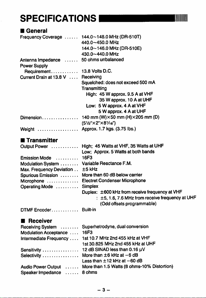
General
Frequency
Antenna
Power
Requirement
Current
Dimension
Weight
■
Output
Emission
Modulation
Max.
Spurious
Microphone
Operating
DTMF
Coverage
Impedance
Supply
Drain
all
Transmitter
Power
Mode
System
Frequency
Emission
Mode
Encoder
3.8 V —
Deviation
..
144.0~148.0MH2(DR-510T)
440.0-450.0
144.0-146.0
430.0-440.0
50
ohms
13.8
Volts
Receiving
Squelched:
Transmitting
High:
Lew: 5 W
140
mm
MHz
MHz
(DR-510E)
MHz
unbalanced
D.C.
does
not
exceed
45 W approx.
35 W approx.
approx. 4 A
5 W approx. 4 A
(W) x 50
mm
9.5 A at
10 A at
(H)
500
at
VHF
at
UHF
x205
(5y2"x2"x8yi6")
Approx.
1.7
kgs.
(3.75
ibs.)
High;
45
Watts
at
VHF,
35
Low;
Approx. 5 Watts
16F3
Variable
±5
More
Electret
Reactance
kHz
than
Condenser
60
dB
below
Watts
at
both
F.M.
carrier
Microphone
Simplex
Duplex:
Built-In
±600
kHz
:
±5,1.6,7.6
(Odd
Offsets
from
receive
MHz
from
programmable)
mA
VHF
UHF
mm
(D)
at
UHF
bands
frequency
receive
frequency
at
VHF
at
UHF
■
Recelver
Receiving
Modulation
Intermediate
System
Acceptance — 16F3
Frequency
Sensitivity
Selectivity
Audio
Power
Speaker
Output
Impedance
Superhetrodyne,
Ist
10.7
Ist
30.825
12
dB
SINAD
More
than
Less
than ± 12
More
than
8
ohms
- 3 -
MHz
MHz
±6
1.5
dual
2nd
455
2nd
less
than
kHz
at
kHz
Watts
455
at
(8
conversion
kHz
at
VHF
kHz
at
UHF
0.16
pV
-6
dB
-60
dB
ohms-10%
Distortion)

OPERATIONI
CONTROL
Front
Panel
O
O
Main
Dia!
Main
dial
Is
transmit/recelve
ory
Channel,
Frequency,
0
Display
The
formation
frequencies,
formation,
etc.
formation.
O
VOL
Tum
crease
counterclockwise
volume.
O
SQL
THE
ate
Normally
clockwise
appears,
goes
and
Panel
LCD
displays
such
Offset,
See
page 6 for
(Volume)
the
control
the
(Squelch)
SQL
control
nolse
during
this
until
and
off.
(Threshold
FUNCTIONS
0
©
used
to
select
frequency,
Frequency
Offset
Frequency.
Step,
Operation
as
transmit/receive
memory
Channel
tone
additional
Control
clockwise
volume,
and
to
decrease
Control
Is
used
no
Signal
control
Is
the
noise
the
BUSY
level)
O
O
<P
the
Mem
Tone
in-
In
frequency
in-
to
in-
turn
it
the
to
ellmln-
periods.
adjusted
just
dls-
Indicator
- 4 -
O
VOl_
SOL.
0
0
H/L
(High/Low)
ThIs
Switch
desired
level.
O
Power
Press
off.
Function
NOTE:
transmitter
Switch
to
turn
Keys
Commands
cated
In
keys.
O F (Function)
ThIs
Is
used
Controlling
i.e.
BEEP,
Function
MW
data
Pages
function
MW,
SKIP,
Operation
is
used
in
memory.
9-10.
BAND
0
0
Is
used
on.
Press
(7
through
Blue
Key
to
access
and
with
the F key
o
o
m]
Switch
to
select
Output
again
15)
underlined
on
transcelver
secondary
labeied
CALL
pages
See
in
LOCK,
W.
8-10.
to
Memory
CH.SP,
the
power
to
turn
Indi-
blue.
See
störe
O
MHz
key
The
MHz
key
frequency
Steps.
Press
the
point
from
MHz
main
buttons
the
Switch
complete
BAND
select
page
o
VFO/M
MHz
and
kHz
the
display.
will
be
dial
or
on
MHz
to
retum
frequency
is
used
VHP
8.
(VFO/MEMORY)
key
VFO/M
is
Memory
Press
between
Channel
CH.SP
select
ming
(D
REV
REV
frequency
LOCK
disable
page
mode.
the
VFO
mode.
is
frequency
and
(Reverse)
is
used
is
used
the
8.
(DSHIFTkey
The
SHIFT
desired
transmitter
peater
or
When
the
mode
Simplex.
key
cycles
is
used
to
up
or
down
key,
and
digits
will
The
changed
pressing
the
key
used
VFO/M
used
scanning.
by
the
microphone.
again
the
display
readout.
with
the F key
or
UHF
to
select
key
and
with
the F key
steps
See
key
to
invert
the
in
Repeater
with
the F key
Function
key
is
used
offset
Cross
Band
is
pressed,
from - to
change
the
in
one
MHz
the
decimal
disappear
frequency
rotating
the
UP/DOWN
Press
or
the
PTT
to
the
band.
See
VFO
to
alternate
the
Memory
for
program-
page
8.
TX
and
RX
mode.
keys.
See
to
select
the
during
re
Operation.
the
offset
-h
to
Dual
in
to
or
to
to
to
(D
TONE
(DR-510E:
The
TONE
A.
Activate
selection
B.
Enable/Disable
Decode
The
BEEP
key
to
Enable/Disable
confirmation
(E)
PRI
(Priority)
The
PRI
Priority
function.
(D
SCAN
The
SCAN
the
frequency
Scan
functions.
The
SKIP
to
skip
when
scanning.
(DCALLkey
(DR-51OE:
The
CALL
Memory
See
page
The
CALL
a
frequency
"C".
See
0
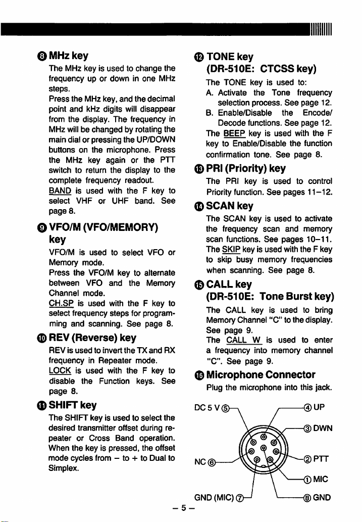
Microphone
Plug
the
DC5V
NC(|>
key
CTCSSkey)
key
is
used
the
Tone
process.
functions.
key
is
used
tone.
See
key
key
is
used
See
key
key
is
used
scan
See
key
is
used
busy
memory
See
Tone
key
9.
W
into
page
is
"C"
is
memory
9.
Channel
Connector
microphone
to:
frequency
See
page
the
Encode/
See
page
with
the
function
page
to
control
pages
11-12.
to
activate
and
memory
pages
10-11.
with
the F key
frequencies
page
8.
Burst
used
to
to
the
display.
used
to
Channel
into
this
@UP
<DDWN
12.
12.
the
8.
key)
bring
enter
jack.
F
- 5 -
GND
(MIC)
®GND
 Loading...