

Page 1

OWNER HANDBOOK
Page 2

WHY CHOOSING
GENUINE PARTS
We really know your car because we invented, designed and built it: we really know every single detail.
At Alfa Romeo Service authorised workshops you can find technicians directly trained by us,
offering quality and professionalism for all service operations.
Alfa Romeo workshops are always close to you for the regular servicing operations, season checks
and practical recommendations by our experts.
With Alfa Romeo Genuine Parts you keep the reliability, comfort and performance features
of your new car unchanged in time: that's why you bought it for.
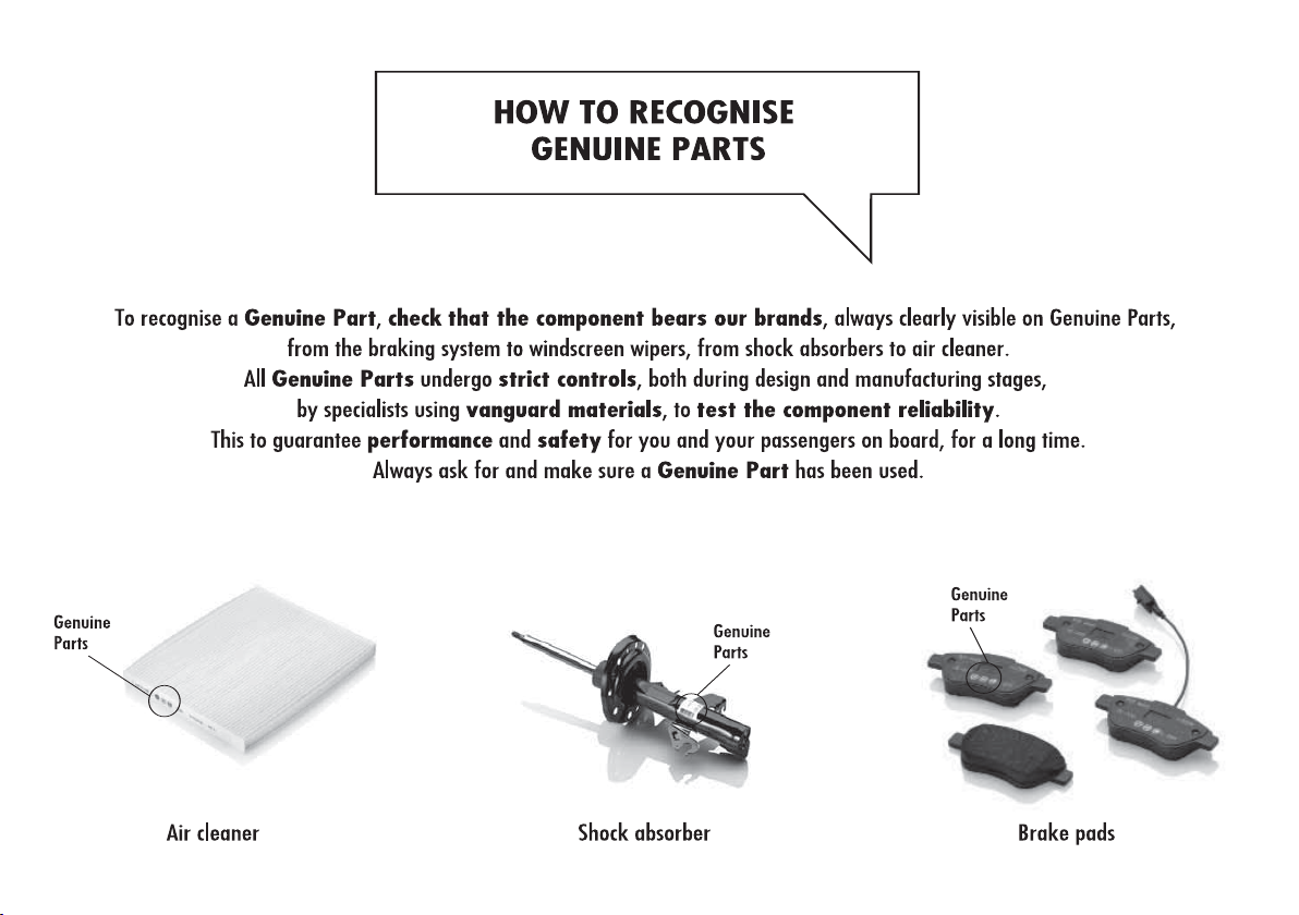
Always ask for Genuine Parts for the components used on our cars; we recommend them because
they come from our steady commitment in research and development of highly innovative technologies.
For all these reasons: rely on Genuine Parts, because they are the only ones
designed by Alfa Romeo for your car.
SAFETY:
BRAKING SYSTEM
ENVIRONMENT: PARTICULATE FILTERS,
CLIMATE CONTROL MAINTENANCE
COMFORT: SUSPENSION
AND WINDSCREEN WIPERS
PERFORMANCE: SPARK PLUGS,
INJECTORS AND BATTERIES
LINEACCESSORI
ROOF RACK BARS, WHEEL RIMS
Page 3
Page 4
Page 5

Dear Customer,
Congratulations on your purchase and thank you for choosing Alfa Romeo.
We have written this handbook to help you get the most out of your new car.
Please read it all the way through before taking your car on the road for the first time.
Here you will find information, tips and important warnings regarding use of your car and how to achieve the best performance from
the technological features of your Alfa Romeo.
The booklet also provides a description of special features as well as tips and essential information for the correct care and mainte-
nance of your Alfa Romeo and safe driving tips.
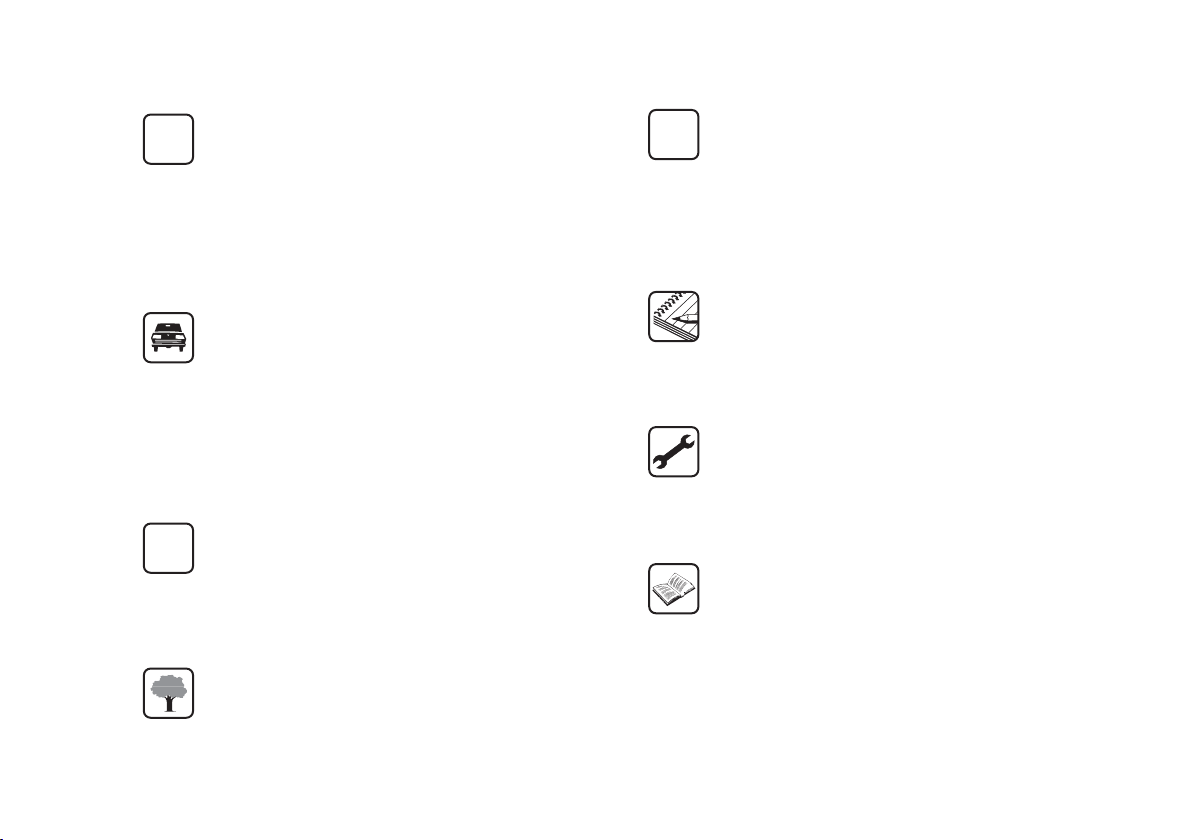
Please read the warnings and indications at the bottom; these are marked with the following symbols:
personal safety
car’s wellbeing
environmental protection.
The enclosed Warranty Booklet lists the services that Alfa Romeo offers to its Customers:
– the Warranty Certificate with terms and conditions for maintaining its validity
– the range of additional services available to Alfa Romeo Customers.
We are confident that these instructions will help you become familiar with your new car and the Alfa Romeo after-sales staff who will
be at your service.
Enjoy the read. Happy motoring!
This Owner Handbook describes all versions of Alfa Giulietta; please consider only the information
relevant to your version, engine and configuration.
The data in this publication is provided by way of example. Fiat Group Automobiles can modify
the specifications of the model described in this publication at any time, for technical or marketing
purposes. For further information, contact an Alfa Romeo Authorised Service Provider.
Page 6
READ THIS CAREFULLY
REFUELLING
Petrol engines: refuel with unleaded petrol with an
K
octane rating (RON) of 95 or higher only.
European specification EN590 only. The use of other products or
mixtures may damage the engine beyond repair and consequently
invalidate the warranty, depending on the damage caused.
STARTING THE ENGINE
Diesel engines: turn the ignition key to MAR and wait for the
and
as soon as the engine starts.
PARKING ON FLAMMABLE MATERIAL
RESPECTING THE ENVIRONMENT
Diesel engines: refuel with diesel fuel compliant with
Petrol engines: make sure that the handbrake is
engaged, set the gearshift lever to neutral, fully depress the
clutch without pressing the accelerator, then turn the ignition key
to AVV and release it as soon as the engine has started.
m
warning lights to turn off; turn the key to AVV and release it
The catalytic converter reaches high temperatures
during operation. Do not park the car on grass, dry
leaves, pine needles or other flammable material: fire
hazard.
ELECTRIC ACCESSORIES
If after having purchased your car you decide to add
쇵
accessories requiring electricity (that may otherwise
cause the battery to gradually lose power), please
contact Alfa Romeo Authorized Services. They can
calculate the overall electric requirement and check that
the car’s electric system can support the required load
CODE CARD
Y
SCHEDULED SERVICING
THE OWNER HANDBOOK CONTAINS…
(for versions/markets where provided)
Keep this in a safe place, not in the car. We recommend
that you always carry the electronic code provided on
the CODE card with you, in case you need to perform
an emergency start.
Correct car maintenance is essential to ensure that the
performance, safety features, environmental
friendliness and low running costs stay in tip-top
condition over the years.
... information, tips and important warnings on the
correct use and maintenance of your car over time. Pay
special attention to the symbols
#
(environmental protection)
"
â
(car integrity).
(personal safety)
The car is fitted with a system that carries out a
continuous diagnosis of the emission-related components
in order to help protect the environment.
Page 7
3
GETTING
TO KNOW
YOUR CAR
SAFETY
STARTING
AND DRIVING
IN AN
EMERGENCY
SERVICING AND
MAINTENANCE
TECHNICAL
SPECIFICATIONS
CONTENTS
GETTING TO KNOW YOUR CAR
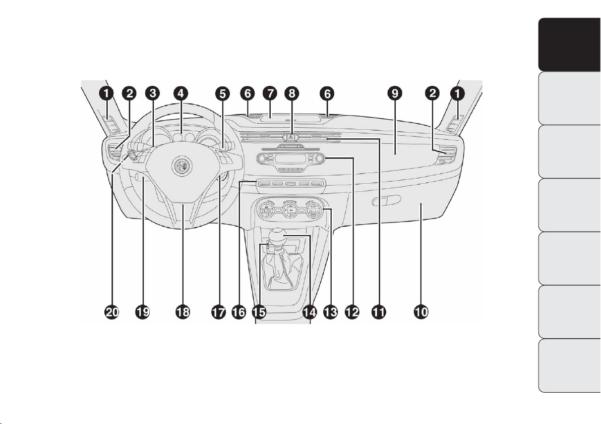
1. Fixed vent for sending air to side windows - 2. Adjustable air vent - 3. External light control stalk - 4. Instrument panel -
5. Windscreen wiper/rear screen wiper/trip computer stalk - 6. Upper adjustable vents - 7. Radio navigator display (for versions/markets, where
provided) - 8. Hazard lights - 9. Passenger front air bag - 10. Glove box - 11. Central adjustable air vents - 12. Radio (for versions/markets,
where provided) - 13. Heating/ventilation/air conditioning controls - 14. Gear shifting stick - 15. “Alfa DNA” system - 16. Control buttons: fog
lights/rear fog lights, Start&Stop system (for versions/markets, where provided), door lock/unlock, AFS light on/off (for versions/markets, where
provided) -17. Ignition device - 18. Driver’s front air bag - 19. Cruise Control stalk (for versions/markets, where provided) - 20. Headlight alignment corrector (for versions/markets, where provided) and Set Up Menu access button.
A0K0074m
fig. 1
DASHBOARD
The presence and position of the controls, the instruments and the indicators may vary according to the versions.
Page 8
4
GETTING
TO KNOW
YOUR CAR
SAFETY
STARTING
AND DRIVING
IN AN
EMERGENCY
SERVICING AND
MAINTENANCE
TECHNICAL
SPECIFICATIONS
CONTENTS
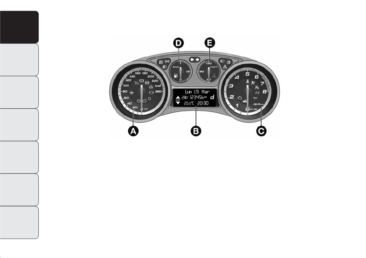
CONTROL PANEL AND INSTRUMENTS
VERSIONS WITH MULTIFUNCTION DISPLAY
A Speedometer (speed indicator)
B Multifunction display
C Rev counter
D Fuel gauge with reserve warning light
E Engine coolant temperature gauge with overheating warning light
m c
Warning lights present on diesel versions only On diesel versions, the end of scale for the rev counter is 6000 rpm
IMPORTANT Instrument panel graphics lighting may vary according to the versions.
A0K0002m
fig. 2
Page 9
5
GETTING
TO KNOW
YOUR CAR
SAFETY
STARTING
AND DRIVING
IN AN
EMERGENCY
SERVICING AND
MAINTENANCE
TECHNICAL
SPECIFICATIONS
CONTENTS
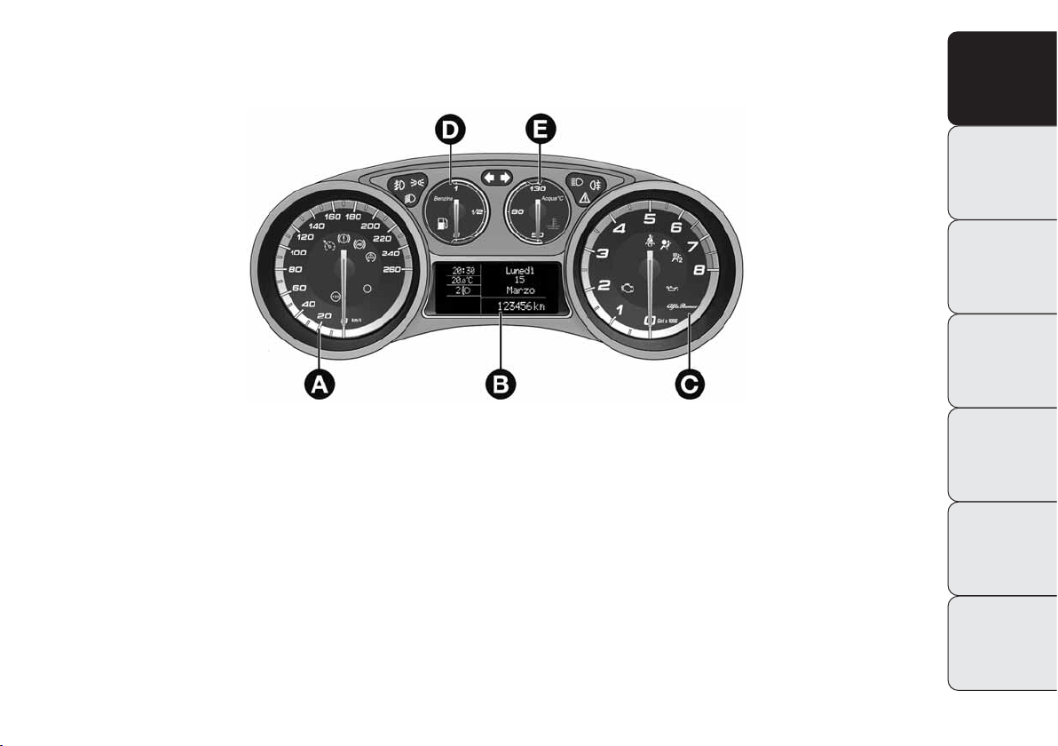
VERSIONS WITH RECONFIGURABLE MULTIFUNCTION DISPLAY
A Speedometer (speed indicator)
B Reconfigurable multifunction display
C Rev counter
D Fuel gauge with reserve warning light
E Engine coolant temperature gauge with overheating warning light
m c
Warning lights present on diesel versions only On diesel versions, the end of scale for the rev counter is 6000 rpm
IMPORTANT Instrument panel graphics lighting may vary according to the versions.
A0K0001m
fig. 3
Page 10

6
GETTING
TO KNOW
YOUR CAR
SAFETY
STARTING
AND DRIVING
IN AN
EMERGENCY
SERVICING AND
MAINTENANCE
TECHNICAL
SPECIFICATIONS
CONTENTS
SPEEDOMETER (SPEED INDICATOR)
This shows the speed of the car.
REV COUNTER
This indicates the engine rpm.
FUEL LEVEL GAUGE
This shows the amount of fuel left in the fuel tank.
0 - tank empty.
1 - tank full
The warning light in the gauge lights up when there are only 8 to
10 litres of fuel remaining in the tank; refuel at the earliest opportunity.
ENGINE COOLANT TEMPERATURE INDICATOR
This gauge indicates the temperature of the engine coolant. The
warning light on the indicator lights up to indicate an increase in
coolant temperature; in the event of this happening, switch off the
engine and contact an Alfa Romeo Authorised Service Provider.
INSTRUMENT PANEL WARNING LIGHTS
General warnings
The warning lights come on in conjunction with a dedicated message and/or a buzzer where appropriate. These indications are
brief and precautionary and as such must not be considered as
exhaustive and/or alternative to the information contained in the
Owner’s Handbook, which you are recommended to read carefully in all cases. Always refer to the information in this chapter in the
event of a failure signal.
Low brake fluid level (red)
When the ignition key is turned to MAR, the warning
light turns on but should go off after a few seconds.
The warning light (or symbol on the display) comes on
when the level of the brake fluid in the reservoir falls below the
minimum level due to possible leaks in the circuit.
A specific message will be shown on the display.
Handbrake on (red)
When the ignition key is turned to MAR, the warning light turns
on but should go off after a few seconds. The warning light (or
symbol on the display) comes on when the handbrake is on. If
the car is moving a buzzer is also triggered.
IMPORTANT If the warning light comes on with the vehicle in motion, check that the handbrake is not engaged.
x
Page 11

7
GETTING
TO KNOW
YOUR CAR
SAFETY
STARTING
AND DRIVING
IN AN
EMERGENCY
SERVICING AND
MAINTENANCE
TECHNICAL
SPECIFICATIONS
CONTENTS
EBD fault
Warning lights
x
(red) and
>
light up at the same
time with the engine running to indicate an EBD system fault or that the system is not available. Early
locking of the rear wheels may occur in the event of
sharp braking, causing the car to swerve. Under these
circumstances drive with extreme caution straight to
the nearest Alfa Romeo Authorised Service Provider
to have the system checked. A specific message appears on the display.
x
>
ABS system fault (amber)
When the ignition key is turned to MAR, the warning
light turns on but should go off after a few seconds.
The warning light (or symbol on the display) lights up to
indicate a system fault. Under these circumstances, the braking system will work as normal but without the extra performance offered
by the ABS system. Drive with caution and visit an Alfa Romeo
Authorised Service Provider at your earliest convenience. A specific message appears on the display.
>
Brake pads worn (amber)
(for versions/markets, where provided)
The warning light (or symbol on the display) switch-
es on when the front and rear brake pads show signs
of wear; under these circumstances have them replaced as soon as
possible. The display will show the dedicated message.
d
Page 12
8
GETTING
TO KNOW
YOUR CAR
SAFETY
STARTING
AND DRIVING
IN AN
EMERGENCY
SERVICING AND
MAINTENANCE
TECHNICAL
SPECIFICATIONS
CONTENTS
Air bag fault (red)
Turning the key to the MAR position illuminates the warn-
ing light, but it should switch off after a few seconds.
The warning light stays on constantly if there is a fault in
the air bag system. A specific message appears on the display.
¬
If the warning light
¬
does not come on when the
key is turned to MAR or if it stays on with the car
in motion (together with the message on the dis-
play) there could be a fault in the restraint systems; under these circumstances, the air bags or pretensioners may
not be deployed in the event of an impact or, more rarely,
they could be deployed accidentally. Contact Alfa Romeo
Authorized Services immediately to have the system
checked.
Fault of the warning light
¬
is indicated by the
warning light
“
(passenger air bag off) flashing
for longer than the normal 4 seconds. In addition,
the air bag system automatically disables the air bags
on the passenger’s side (both front and side air bags, for
versions/markets, where provided). In this case, warning
light¬may not indicate that there is a fault in the restraint systems. Contact Alfa Romeo Authorized Services
immediately to have the system checked.
Passenger air bag/side bags off
(amber)
The“warning light comes on when the front pas-
senger’s air bag and side bag are deactivated. With front
passenger air bag on, when the ignition key is turned to MAR,
the“warning light comes on steadily for several seconds, it flashes for another few seconds and then it should go out.
“
Fault of the warning light
“
is indicated by warning light ¬coming on. In addition, the air bag system automatically deactivates the air bags on pas-
senger side (both front and side air bags, for versions/
markets, where provided). Contact Alfa Romeo Authorized
Services immediately to have the system checked.
Page 13

9
GETTING
TO KNOW
YOUR CAR
SAFETY
STARTING
AND DRIVING
IN AN
EMERGENCY
SERVICING AND
MAINTENANCE
TECHNICAL
SPECIFICATIONS
CONTENTS
Seat belt reminder (red)
(for versions/markets where provided)
The warning light remains on steadily with the car at
stationary and the driver’s seat belt not correctly fastened.
The warning light will flash and a buzzer will sound if the vehicle
is in motion and the front seat belts are not correctly fastened.
Contact Alfa Romeo Authorized Services if you wish to permanently
deactivate the S.B.R. (Seat Belt Reminder) system buzzer.
The system can be reactivated using the setup Menu.
<
Low battery charge (red)
(for versions/markets where provided)
The warning light comes on when the ignition key is
turned to MAR, but it should go out as soon as the engine has started (with the engine running at idle speed a brief delay before going out is acceptable).
Contact Alfa Romeo Authorized Services if the warning light (or
symbol on the display) remains only or blinks.
w
Dual Pinion active steering failure
(red)
(for versions/markets, where provided)
The warning light comes on when the ignition key is
turned to MAR, but it should switch off after a few seconds. If the warning light (or symbol on the display) remains on,
you may not have steering assistance and the effort required to operate the steering wheel could be notably increased; steering is,
however, possible. If this occurs, contact Alfa Romeo Authorized
Services. The display will show a dedicated message.
IMPORTANT The steering system will need to be initialised after disconnecting the battery. A warning light will come on to indicate
this. Simply turn the steering wheel all the way to one end or simply drive on a straight line for a few hundred metres.
g
Page 14

10
GETTING
TO KNOW
YOUR CAR
SAFETY
STARTING
AND DRIVING
IN AN
EMERGENCY
SERVICING AND
MAINTENANCE
TECHNICAL
SPECIFICATIONS
CONTENTS
ON CONSTANTLY: Low engine oil pressure (red)
FLASHING: Exhausted engine oil
(for versions/markets, where provided - red)
When the ignition key is turned to MAR, the warning light
switches on, but it should go out as soon as the engine is started.
1. Low engine oil pressure
The warning light turns on constantly along with a message on the
display (for versions/markets where provided) when the system
detects that engine oil pressure is low.
v
If the warning light
v
turns on when the car is
travelling (on some versions, together with the
message on the display), stop the car immediate-
ly and contact Alfa Romeo Authorized Services.
2. Exhausted engine oil
(for versions/markets, where provided)
The warning light comes on flashing and a specific message will
appear on the display (for versions/markets where provided). The
warning light may flash in the following ways, depending on the
versions:
❍
for 1 minute every two hours;
❍
for three minute cycles with the warning light off for intervals
of five seconds until oil is changed.
After the initial warning, each time the engine is started up, the
warning light will continue to flash in the same ways as described
above, until the oil is changed. A specific message will appear on
the display (for versions/markets where provided) in addition to
the warning light.
Flashing of the warning light is not a fault but indicates that the
oil needs to be changed as a consequence of normal use.
Note that engine oil degrades faster under the following circumstances:
❍
mainly urban use of the car , requiring more frequent regeneration of the DPF;
❍
use of the car for short drives, in which the engine does not
have time to reach its regular operating temperature
❍
repeated interruptions to the regeneration process signalled by
the DPF warning light coming on.
Exhausted engine oil should be replaced as soon
as possible after the warning light comes on, and
never more than 500 km after it first comes on.
Failure to comply with the instructions above may result
in severe damage to the engine and invalidate the warranty. Remember that the operation of this warning light
is not related to the amount of oil in the engine. Therefore, do not simply top up when the light starts flashing.
Page 15

11
GETTING
TO KNOW
YOUR CAR
SAFETY
STARTING
AND DRIVING
IN AN
EMERGENCY
SERVICING AND
MAINTENANCE
TECHNICAL
SPECIFICATIONS
CONTENTS
Hot engine coolant (red)
When the ignition key is turned to MAR, the warning
light turns on but should go off after a few seconds.
The warning light turns on when the engine is over-
heated. A specific message will be shown on the display.
If the warning light comes on, proceed as follows:
❍
when driving normally: stop the car, switch off the engine and
check that the water level in the reservoir is not below the MIN
mark. If it is not, wait for a few minutes for the engine to cool
down then slowly and carefully open the cap, top-up with coolant
and check that the level is between the MIN and MAX marks.
Also visually check for leaks. If the warning light comes on again
at the next engine start-up, contact Alfa Romeo Authorized Services.
❍
if the car is used under demanding conditions (e.g. towing trailers uphill or fully loaded): slow down and, if the light stays on,
stop the car. Stop for two or three minutes with the engine running and slightly accelerated to assist better coolant circulation.
Then switch the engine off. Check correct fluid level as described
above.
IMPORTANT On particularly demanding journeys, it is advisable to
keep the engine on and slightly accelerated for a few minutes before switching it off.
u
Door open (red)
(for versions/markets, where provided)
The warning light (or symbol on the display) comes
on when one or more doors or the boot are not perfectly
closed. An acoustic signal is activated with the doors open and
the car moving. On some versions, the warning light (or symbol
on the display) also lights up when the bonnet is not perfectly
closed.
´
EOBD/injection system fault (amber)
Under normal conditions, the warning light comes on
when the ignition key is turned to MAR, but should
go off as soon as the engine is started.
If the warning light remains on or comes on whilst driving, that
means that the injection system is not working properly; in particular, if the warning light comes on constantly, this indicates a malfunction in the supply/ignition system that could cause excessive
exhaust emissions, a possible loss of performance, poor driveability and high fuel consumption.
A specific message is displayed on certain versions.
Under these conditions, you can continue travelling at moderate
speed without demanding excessive effort from the engine. Prolonged use of the car with the warning light on may cause damage. Contact Alfa Romeo Authorized Services as soon as possible.
The warning light goes out after the fault disappears, but the indication is stored in the system.
U
Page 16
12
GETTING
TO KNOW
YOUR CAR
SAFETY
STARTING
AND DRIVING
IN AN
EMERGENCY
SERVICING AND
MAINTENANCE
TECHNICAL
SPECIFICATIONS
CONTENTS
VDC system (amber)
(for versions/markets, where provided)
When the ignition key is turned to MAR, the warning
light turns on but should go off after a few seconds. If
the warning light does not go out, or if it remains lit up when driving, contact Alfa Romeo Authorized Services. A specific message
is displayed on certain versions. The warning light will flash while
driving to indicate that the VDC system is intervening.
ASR fault
When the ignition key is turned to MAR, the warning light turns
on but should go off after a few seconds. If the warning light does
not go out, or if it remains lit up when driving, contact Alfa Romeo
Authorized Services. A specific message is displayed on certain versions. The warning light will flash while driving to indicate that
the ASR system is intervening.
Hill Holder fault
This warning light comes on, on some versions together with the
*
symbol and a message in the display, in the event of a Hill Holder system fault. In this case, contact your nearest Alfa Romeo Authorized Services.
á
NOTE (petrol engines only)
If the warning light is flashing, this indicates that the catalytic
converter may be damaged.
If the warning light comes on intermittently, release the accelerator pedal to lower the speed of the engine until the warning light
stops flashing; continue the journey at moderate speed, trying to
avoid driving conditions that may cause further flashing and contact
an Alfa Romeo Authorised Service Provider as soon as possible.
Contact Alfa Romeo Authorized Services as soon as
possible if the
U
warning light does not light up
or if, while travelling, the warning light comes on
either fixed or blinking (in combination with a message
on the display on some versions). The operation of the
U
warning light may be checked by traffic police using appropriate equipment. Follow the laws in force in the country where you are driving.
Page 17
13
GETTING
TO KNOW
YOUR CAR
SAFETY
STARTING
AND DRIVING
IN AN
EMERGENCY
SERVICING AND
MAINTENANCE
TECHNICAL
SPECIFICATIONS
CONTENTS
Alfa Romeo CODE fault/
alarm fault (amber)
(for versions/markets, where provided)
The warning light (or symbol on the display) will come
on (on some versions, with a message on the display) to indicate
an Alfa Romeo CODE system or alarm fault(for versions/markets,
where provided): In this case, contact Alfa Romeo Authorized Services.
Break-in attempt
If this warning light flashes or, on some versions, if the symbol
appears in the display (together with the associated message) this
indicates a break-in attempt. Contact Alfa Romeo Authorized Services as soon as possible.
Y
Glow plug preheating
(diesel versions) (amber)
When the key is turned to MAR, the warning light
comes on and it will go out when glow plugs reach the
preset temperature. THE engine may be started immediately after the warning light goes out.
IMPORTANT In mild or high temperature conditions, the warning
light comes on for a very short time only.
Glow plugs preheating fault
(diesel versions)
The warning light will flash (a message in the display will appear
on the display, on some versions) to indicate a fault in the glow
plugs preheating system. Contact Alfa Romeo Authorized Services
as soon as possible to eliminate the fault.
m
Water in fuel filter
(diesel versions) (amber)
The warning light remains on constantly when driving
(together with a message in the display), to indicate the
presence of water in the diesel fuel filter.
c
The presence of water in the fuel system circuit may
cause severe damage to the injection system and
irregular engine operation. If the
c
warning light
comes on in the instrument panel (together with a message in the display) contact Alfa Romeo Authorized Services as soon as possible to bleed the system. Water may
have entered the tank if this appears immediately after
refuelling: if this happens, switch the engine off immediately and contact Alfa Romeo Authorized Services.
Page 18
14
GETTING
TO KNOW
YOUR CAR
SAFETY
STARTING
AND DRIVING
IN AN
EMERGENCY
SERVICING AND
MAINTENANCE
TECHNICAL
SPECIFICATIONS
CONTENTS
Fuel reserve – Limited range (amber)
This warning light comes on when about 8 to 10 litres
of fuel are left in the tank. A warning message will ap-
pear on the display (some versions only) when the remaining range less than approximately 50 km (or equivalent in
miles).
K
If the warning light flashes with the car in motion,
contact Alfa Romeo Authorized Services.
Cruise Control (green)
(for versions/markets, where provided)
The warning light comes on when the key is turned to
MAR, but should go out after a few seconds if the Cruise
Control function is off. The warning light comes on when the Cruise
Control wheel is turned to the ON position (see the “Cruise Control” paragraph in this chapter). A specific message appears on the
display.
Ü
DPF (particulate trap) cleaning in
progress (diesel versions with DPF
only) (amber)
When the ignition key is turned to MAR, the warning light
turns on but should go off after a few seconds. The warning light
stays on constantly to notify the driver that the DPF system needs
to eliminate captured pollutants (particulate) by the regeneration
process.
The warning light does not come on during every DPF regeneration, but only when driving conditions require notification to the driver. The warning light will go off if the car stays in motion until
regeneration has been completed.
The process normally takes about 15 minutes. Optimal conditions
for completing the process are achieved by travelling at 60 km/h
with engine revs above 2000 rpm.
Operation of this warning light does not indicate a fault and the car
does not need to be taken to a workshop. A specific message will
appear on the display when the warning light comes on (for versions/markets where provided).
h
Page 19
15
GETTING
TO KNOW
YOUR CAR
SAFETY
STARTING
AND DRIVING
IN AN
EMERGENCY
SERVICING AND
MAINTENANCE
TECHNICAL
SPECIFICATIONS
CONTENTS
Speed limit exceeded (red)
(for versions/markets, where provided)
The warning light (for versions/markets where pro-
vided) comes on when the speed exceeds 120 km/h.
When the car exceeds the speed limit set in the setup Menu (e.g.
120 km/h), on some versions a message and a symbol are shown
in the display and an acoustic signal is activated.
X
Always drive at a speed appropriate to the traffic
conditions, the weather and the laws in force. The
engine may be turned off while the DPF light is on;
however, repeated interruption of the regeneration process
may result in premature degradation of the engine oil.
For this reason, it is always advisable to wait for the light
to go off before turning off the engine, following the instructions appearing above. It is not a good idea to complete DPF regeneration with the vehicle stationary.
Generic fault (amber)
(for versions/markets, where provided)
The warning light turns on in the following circumstances:
Contact Alfa Romeo Authorized Services as soon as possi-
ble to eliminate the fault.
Exterior lights fault
See the section on warning light 6.
Brake lights fault
See description in the “Brake lights fault” section.
Fuel cut-off
This warning light comes on when the fuel cut-off inertia switch is
triggered. A specific message will be shown on the display.
Start&Stop fault
(for versions/markets, where provided)
The warning light comes on when a fault is detected in the
Start&Stop system.
Rain sensor fault
(for versions/markets where provided)
The warning light comes on when a rain sensor fault is detected.
è
Page 20

16
GETTING
TO KNOW
YOUR CAR
SAFETY
STARTING
AND DRIVING
IN AN
EMERGENCY
SERVICING AND
MAINTENANCE
TECHNICAL
SPECIFICATIONS
CONTENTS
Parking sensor fault
(for versions/markets where provided)
See the section on warning light
t
.
Rain sensor fault
(for versions/markets where provided)
This warning light comes on when a dusk sensor fault is detected.
AFS adaptive lights fault
(for versions/markets, where provided)
The warning light comes on when an AFS adaptive light fault is detected (see “AFS adaptive lights” in this chapter). A specific message will be shown on the display.
Anti-pinch system fault
The warning light will come on when an anti-pinch system fault
is detected. A specific message will be shown on the display.
Engine oil pressure sensor fault
The warning light turns on when an engine oil pressure sensor fault
is detected. A specific message will be shown on the display.
Rear fog lights (amber)
The warning light comes on when the rear fog lights
are on. The LED over 4 button will also light up.
4
Fog lights (green)
The warning light comes on when the fog lights are
on. The LED over 5 button
5
will also light up.
5
Side lights (green)
This warning light comes on when the side lights are
turned on.
Follow me home (green)
The warning light comes on (in combination with a message on
the display) when this device is used (see “Follow me home device” in this chapter).
3
Page 21

17
GETTING
TO KNOW
YOUR CAR
SAFETY
STARTING
AND DRIVING
IN AN
EMERGENCY
SERVICING AND
MAINTENANCE
TECHNICAL
SPECIFICATIONS
CONTENTS
Dipped beam headlights (green)
The warning light comes on when the dipped beam
headlights are on.
2
U
Main beam headlights (blue)
The warning light comes on when the main beam head-
lights are on.
1
Left direction indicator (green)
This warning light comes on when the direction indi-
cator stalk is moved downwards or when the hazard
warning light button is pressed.
Right direction indicator (green)
The warning light comes on when the direction indica-
tor stalk is moved upwards or when the hazard warn-
ing light button is pressed.
R
E
Start&Stop system on/off
(for versions/markets, where provided)
Start&Stop system fault
Turning the Start&Stop system on
A message will appear on the display when the Start&Stop system
is on. The LED on the
T
button on control panel in the dashboard
(see “Start&Stop system” in this chapter) is off.
Turning the Start&Stop off
❍
Versions with multifunction display: a message will appear on
the display when the Start&Stop system is off.
❍
Versions with reconfigurable multifunction display: The
T
symbol and a message will appear on the display when the
Start&Stop system is off.
The LED on the
T
button will be on when the system is off.
Start&Stop system fault
Symbol
U
(versions with multifunction display) or
j
(versions
with reconfigurable multifunction display) will flash to indicate a
Start&Stop system fault. For versions/markets, where provided,
a message is also displayed. In this case, contact Alfa Romeo Authorized Services.
Page 22
18
GETTING
TO KNOW
YOUR CAR
SAFETY
STARTING
AND DRIVING
IN AN
EMERGENCY
SERVICING AND
MAINTENANCE
TECHNICAL
SPECIFICATIONS
CONTENTS
Possible presence of ice on the road
On versions equipped with reconfigurable multifunc-
tion display, a message + symbol will appear when
the outdoor temperature falls to or below 3°C.
On versions with multifunctional display, only the message is shown.
IMPORTANT In the event of outdoor temperature sensor fault, dashes are shown on the display instead of the value.
√
Fuel cut-off
On some versions the display will show a message +
symbol if the fuel cut-off trips. For the fuel cut-off sys-
tem reactivation procedure see paragraph “Fuel cut-off
system” in this chapter.
s
Exterior lights fault
On some versions, a message + symbol will appear
on the display if a fault is detected in one of the fol-
lowing lights:
– daytime lights (DRL)
– sidelights/taillights
– direction indicators
– rear fog lights
– number plate lights.
The fault relating to these lights could be: one or more blown bulbs,
a blown protection fuse or a break in the electric connection.
W
Boot open
On some versions, a message + symbol on the dis-
play are shown when the boot is open.
R
Bonnet open
On some versions, a message + symbol on the display
are shown when the bonnet is open.
S
Page 23

19
GETTING
TO KNOW
YOUR CAR
SAFETY
STARTING
AND DRIVING
IN AN
EMERGENCY
SERVICING AND
MAINTENANCE
TECHNICAL
SPECIFICATIONS
CONTENTS
Rain sensor fault
(for versions/markets where provided)
On some versions, a message + symbol will be shown
on the display if a dusk sensor fault is detected.
1
Parking sensor fault
(for versions/markets where provided)
On some versions, a message + symbol will be shown
on the display if a parking sensor fault is detected.
Rain sensor fault
(for versions/markets where provided)
On some versions, a message + symbol will appear on
the display if a rain sensor fault is detected.
u
t
Brake lights fault
On some versions, a message + symbol will appear on
the display if a brake light fault is detected. The fault may be caused
by a blown bulb, a blown protection fuse or an interruption of the
electric connection.
T
Drive mode display (“Alfa DNA” system)
(for versions/markets, where provided)
On versions equipped with a reconfigurable multifunction display,
a message + symbol associated with the selected driving mode “DYNAMIC”, “NORMAL” or “ALL WEATHER” - is shown. A warning message is shown on the display if one of these driving modes
is not available.
On versions equipped with multifunction display, a letter (d or a)
associated with the selected driving mode is shown together with
a dedicated message.
Page 24
20
GETTING
TO KNOW
YOUR CAR
SAFETY
STARTING
AND DRIVING
IN AN
EMERGENCY
SERVICING AND
MAINTENANCE
TECHNICAL
SPECIFICATIONS
CONTENTS
DISPLAY
The car may be equipped with a multifunction display/multifunction reconfigurable display which, in accordance with the settings made, can display useful information when driving.
With the ignition key removed, the display lights up and shows the
time and total odometer reading (in km or miles) for a few seconds when a door is opened/closed.
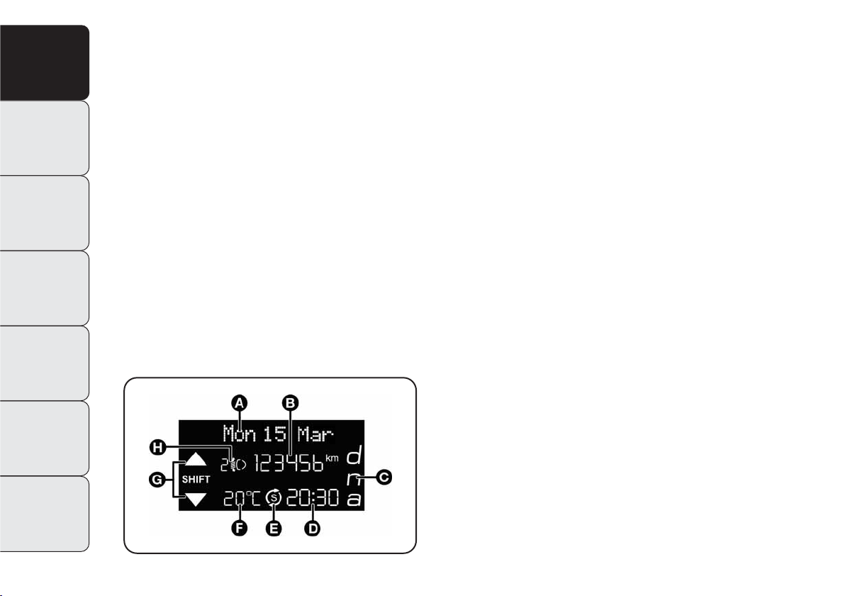
MULTIFUNCTION DISPLAY “STANDARD”
SCREEN fig. 6
The following information is shown on the display:
A. Date
B. Odometer (distance covered in km or miles)
C. Driving mode selected using “Alfa DNA” (dynamic control sys-
tem) (for versions/markets, where provided)
– d = Dynamic
– n = Normal
– a = All Weather
D. Time (always displayed, even with the key extracted and the
front doors closed)
E Start&Stop function indicator (for versions/markets, where
provided)
F. Outside temperature
G Gear Shift Indicator (for versions/markets where provided)
H. Headlight alignment position (dipped headlamps on only)
fig. 6
A0K1222g
Page 25
21
GETTING
TO KNOW
YOUR CAR
SAFETY
STARTING
AND DRIVING
IN AN
EMERGENCY
SERVICING AND
MAINTENANCE
TECHNICAL
SPECIFICATIONS
CONTENTS
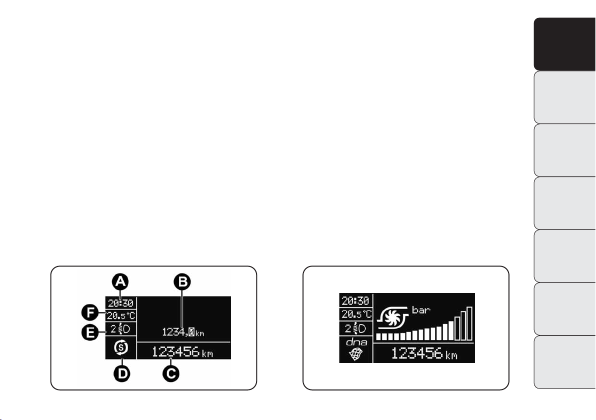
RECONFIGURABLE MULTIFUNCTION
“STANDARD” DISPLAY fig. 7
The following information is shown on the display:
A. Time
B. Trip meter (km or miles)
C. Odometer (display of distance travelled in kilometres/miles)
D. State indicator (e.g. doors open, ice on road, etc.)/Start&Stop
function indicator (for versions/markets, where provided)/
Gear Shift Indicator (for versions/markets, where provided)
E. Headlamp alignment position (only with dipped headlamps
on).
F. Outside temperature
The turbocharger pressure will appear on some versions when
“DYNAMIC” driving mode is selected (see “Alfa DNA system” in
this chapter), fig. 8.
fig. 7
A0K0005m
fig. 8
A0K0006m
Page 26
22
GETTING
TO KNOW
YOUR CAR
SAFETY
STARTING
AND DRIVING
IN AN
EMERGENCY
SERVICING AND
MAINTENANCE
TECHNICAL
SPECIFICATIONS
CONTENTS
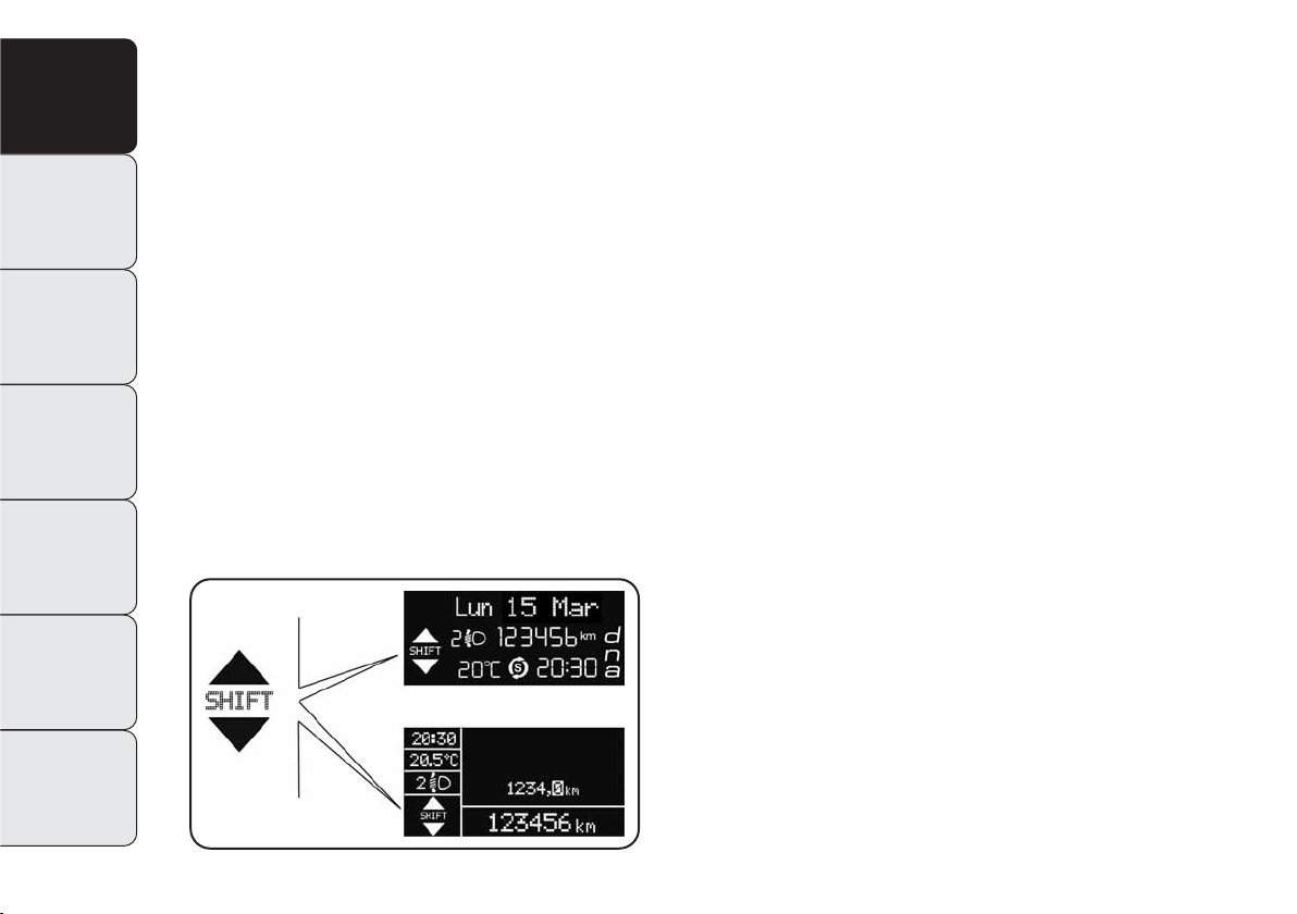
GEAR SHIFT INDICATOR
The GSI system (Gear Shift Indicator) suggests to shift gear by
showing an indication on the control panel (see fig. 9).
Shifting when indicated by GSI will help the driver save fuel.
For fuel-effective driving, select Normal or All Weather mode and
follow the suggestions of the Gear Shift Indicator where possible.
When the SHIFT UP icon (
N
SHIFT) appears on the display, the
GSI is suggesting to select a higher gear and when the SHIFT DOWN
(OSHIFT) icon it is suggesting that a lower gear should be selected.
NOTE The indication on the instrument panel stays on until the
driver shifts or until the driving conditions return to a situation in
which shifting is not required to reduce consumption.
fig. 9
A0K0050m
Page 27
23
GETTING
TO KNOW
YOUR CAR
SAFETY
STARTING
AND DRIVING
IN AN
EMERGENCY
SERVICING AND
MAINTENANCE
TECHNICAL
SPECIFICATIONS
CONTENTS
WELCOME MOVEMENT
On some versions, the following occurs when the key is turned to
MAR:
❍
quick movement (up and down) of the speedometer and rpm
gauge;
❍
illumination of graphic symbols/display;
❍
an animated graphic representation of the vehicle profile appears on the display.
Gauge movement
❍
If the key is removed from the ignition switch whilst the gauges
are moving, they immediately return to their initial position.
❍
Once they have reached the end-of-scale values the gauges rest
on the value indicated by the car.
❍
The movement of the gauges stops when the engine is started.
Illumination of graphic symbols/display
A few seconds after the key is inserted, the gauges, graphic symbols and display light up in sequence.
Graphic animation display
When the key is removed from the ignition switch (with the doors
closed), the display remains lit up and shows a graphic animation.
The display illumination is then dimmed gradually until it goes
out completely.
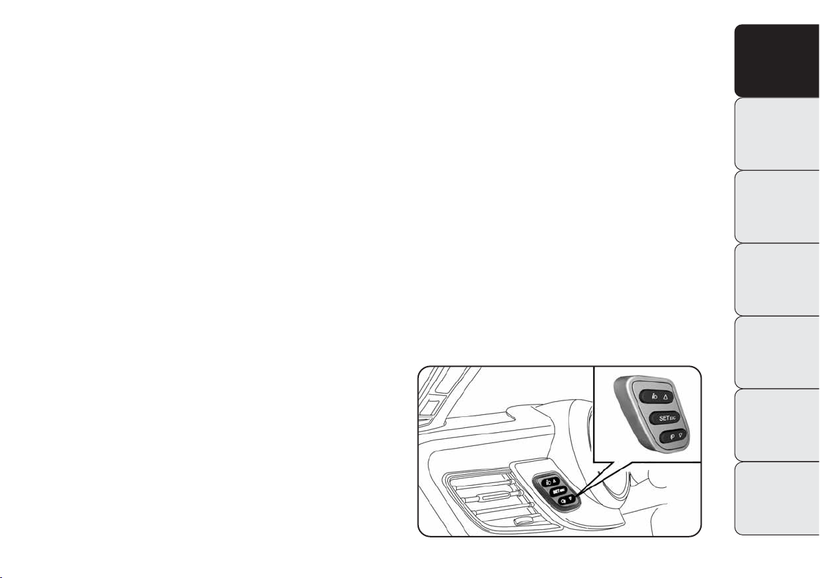
CONTROL BUTTONS fig. 10
Ò ▲
: To scroll up the screen and the menu options or increase the
displayed value.
“SET ESC”: Briefly press to access the menu and/or go to the next
screen or confirm your choice. Hold down to go back
to the standard screen.
▼: To scroll down the screen and the menu options or decrease
the displayed value.
IMPORTANT Buttons “
Ò ▲
“ and “▼
“ activate different func-
tions in the following situations:
❍
to scroll the menu options upwards and downwards;
❍
to increase or decrease values during settings.
fig. 10
A0K0094m
Page 28

24
GETTING
TO KNOW
YOUR CAR
SAFETY
STARTING
AND DRIVING
IN AN
EMERGENCY
SERVICING AND
MAINTENANCE
TECHNICAL
SPECIFICATIONS
CONTENTS
The menu includes the following items:
– MENU
– SPEED BEEP
– HEADLIGHT SENSOR (for versions/markets, where provided)
– RAIN SENSOR (for versions/markets where provided)
– ON/TRIP B DATA
– SET TIME
– SET DATE
– FIRST PAGE (for versions/markets where provided)
– SEE RADIO
– AUTOCLOSE
– MEASURES
– LANGUAGE
– ALERTS VOLUME
– BUTTONS VOLUME
– SEAT BELT REMINDER
– SERVICE
– PASSENGER AIR BAG
– DAY LIGHTS
– COURTESY LIGHTS
– MENU EXIT
NOTE Some menu items are shown on the navigator display in models equipped with radio-navigation systems (for versions/markets,
where provided).
SETUP MENU
The menu comprises a series of items which can be selected using the “
Ò ▲
“ and “▼
“ buttons to access the different selection and setting operations illustrated in the following paragraphs.
Some items also have a sub-menu.
The menu can be activated by briefly pressing the SET ESC button.
Page 29

25
GETTING
TO KNOW
YOUR CAR
SAFETY
STARTING
AND DRIVING
IN AN
EMERGENCY
SERVICING AND
MAINTENANCE
TECHNICAL
SPECIFICATIONS
CONTENTS
Selecting an option from the main
menu without a submenu:
– briefly press SET ESC to select the main menu option you wish
to set;
– repeatedly press “
Ò ▲
“ or “▼
“ to select the new setting;
– press the SET ESC button to store the new setting and go back
to the previous main menu option.
Selecting an option from the main menu with
a submenu:
– press the SET ESC button to display the first submenu option;
– repeatedly press “
Ò▲
“ or “▼
“ to scroll through all the sub-
menu options;
– briefly press the SET ESC button to select the displayed submenu
option and open the relevant setup menu;
– repeatedly press “
Ò ▲
“ or “▼
“ to select the new setting
of this submenu item;
– briefly press the SET ESC button to store the new setting and
go back to the previous submenu option.
Page 30

26
GETTING
TO KNOW
YOUR CAR
SAFETY
STARTING
AND DRIVING
IN AN
EMERGENCY
SERVICING AND
MAINTENANCE
TECHNICAL
SPECIFICATIONS
CONTENTS
MENU ITEMS
Menu
This item is used access the Setup Menu.
Press “
Ò ▲
“ or “▼
“ to select the various menu items.
Hold down the SET ESC button to return to the standard screen.
Speed warning (speed limit)
With this function is possible to set the car speed limit (km/h or
mph); when this limit is exceeded the driver is alerted. To set the
desired speed limit, proceed as follows:
– briefly press the SET ESC button: the display shows the words
Speed Beep;
– press button “
Ò ▲
“ or“▼
“ to activate (On) or deactivate
(Off) the speed limit;
– if the function is on, press “
Ò ▲
“ or “▼
“ to select the re-
quired speed limit and then press SET ESC to confirm;
IMPORTANT Setting is possible between 30 and 200 km/h, or 20
and 125 mph, according to the previously stored unit. See the
“Measures” paragraph described below. The setting will increase/decrease by five units each time button
Ò ▲/▼is
pressed. Hold down
Ò ▲/▼button to increase/decrease
the setting rapidly. Complete the setting by repeatedly pressing the
button when you approach the required value.
– briefly press the SET ESC button to go back to the menu screen
or hold the button to go back to the standard screen without saving.
To cancel the setting, proceed as follows:
– briefly press the SET ESC button: ON flashes in the display;
– press ▼
button: OFF flashes in the display;
– briefly press the SET ESC button to go back to the menu screen
or hold the button down to go back to the standard screen without saving.
Page 31

27
GETTING
TO KNOW
YOUR CAR
SAFETY
STARTING
AND DRIVING
IN AN
EMERGENCY
SERVICING AND
MAINTENANCE
TECHNICAL
SPECIFICATIONS
CONTENTS
Headlight sensor (Automatic headlight/dusk
sensor sensitivity adjustment)
(for versions/markets, where provided)
This function is used to turn the headlights on or off according to
external lighting conditions.
The dusk sensor sensitivity can be adjusted according to 3 levels
(level 1= minimum sensitivity, level 2= average sensitivity, level
3= maximum sensitivity); the greater the sensitivity set, the less
the external light variation needed to control turning on the lights
(e.g. with a setting on level 3 at sunset the headlights are expected
to come on in relation to levels1 and 2).
Proceed as follows to set:
– briefly press SET ESC: the previously set brightness level flash-
es in the display;
– press “
Ò ▲
“ or “▼
“ to select;
– briefly press the SET ESC button to go back to the menu screen
or hold the button down to go back to the standard screen without saving.
Rain sensor (sensitivity adjustment)
(for versions/markets where provided)
This function is used to adjust the rain sensor sensitivity to four
levels.
To set the required sensitivity level, proceed as follows:
– briefly press SET ESC button: the previously set sensitivity level
will flash on the display;
– press “
Ò ▲
“ or“▼
“ to select;
– press the SET ESC button to go back to the menu screen or
hold the button down to go back to the standard screen without
saving.
Page 32

28
GETTING
TO KNOW
YOUR CAR
SAFETY
STARTING
AND DRIVING
IN AN
EMERGENCY
SERVICING AND
MAINTENANCE
TECHNICAL
SPECIFICATIONS
CONTENTS
On/Trip B data (trip B on)
With this function is possible to turn the Trip B display (trip meter) on and off. For more information see the “Trip computer” paragraph.
For activation/deactivation, proceed as follows:
– briefly press the SET ESC button again: the display flashes On
or Off depending on what was previously set;
– press “
Ò ▲
“ or “▼
“ to select;
– briefly press the SET ESC button to go back to the menu screen
or hold the button down to go back to the standard screen without saving.
Set time (Clock)
With this function is possible to set the clock through two submenus: “Time” and “Format”.
To carry out the adjustment, proceed as follows:
– briefly press SET ESC button: the display shows the two sub-
menus “Time” and “Format”;
– press “
Ò ▲
“ or“▼
“ to go from one submenu to the next;
– once you have selected a submenu, briefly press SET ESC;
- when accessing the “Time” submenu: brefly pressing SET ESC
button: the minutes flash in the “time” mode;
– press “
Ò ▲
“ or“▼
“ to select;
– brefly press SET ESC button: “the minutes” flash in the display;
– press “
Ò ▲
“ or“▼
“ to select.
IMPORTANT The setting will increase or decrease by one unit each
time “
Ò ▲
“ or “▼
“ is pressed. Hold the button down to increase/decrease the setting rapidly. Complete the setting by repeatedly pressing the button when you approach the required setting.
Page 33

29
GETTING
TO KNOW
YOUR CAR
SAFETY
STARTING
AND DRIVING
IN AN
EMERGENCY
SERVICING AND
MAINTENANCE
TECHNICAL
SPECIFICATIONS
CONTENTS
– when accessing the “Format” submenu: briefly press button
SET ESC: the previously set display format will flash on the display;
– press “
Ò ▲
“ or “▼
“ to select the “24h” or “12h” mode.
When you have made the required adjustments, briefly press SET
ESC button to go back to the submenu screen or hold the button
down to go back to the main menu screen without saving.
– press SET ESC button again to go back to the standard screen
or main menu, depending on which point in the menu you have
reached.
Set date
With this function is possible to change the date (day - month year).
To update, proceed as follows:
– briefly press SET ESC button: the “year” flashes on the display;
– press “
Ò ▲
“ or“▼
“ button to select;
– briefly press SET ESC: the “month” flashes on the display;
– press “
Ò ▲
“ or“▼
“ to select;
– briefly press SET ESC: the “day” flashes on the display;
– press “
Ò ▲
“ or“▼
“ button to select.
IMPORTANT The setting will increase or decrease by one unit each
time “
Ò ▲
“ or “▼
“ button is pressed. Hold the button down
to increase/decrease the setting rapidly and automatically. Complete the setting by single pressing the button when you approach
the required value.
– press the SET ESC button to go back to the menu screen or
hold the button down to go back to the standard screen without
saving.
Page 34

30
GETTING
TO KNOW
YOUR CAR
SAFETY
STARTING
AND DRIVING
IN AN
EMERGENCY
SERVICING AND
MAINTENANCE
TECHNICAL
SPECIFICATIONS
CONTENTS
First page (information display on home page)
(for versions/markets, where provided)
This function is used to choose the information you would like to
see on the main screen. You can view the date or the trip meter.
To make your choice, proceed as follows:
– briefly press SET ESC button: “First page” will appear on the dis-
play;
– briefly press SET ESC button again to show the display options:
“Date” and “Engine info”;
– press “
Ò ▲
“ or“▼
“ button to select the information you
wish to see on the main page of the display;
– briefly press SET ESC button to go back to the menu screen or
hold the button down to go back to the standard screen without
saving.
When the key is turned to MAR and the initial check stage is over,
the display will show the information selected via the “First page”
menu function.
See radio (audio information display)
This function is used to shows information relating to the car radio on the display.
– Radio: selected radio station frequency or RDS message, automatic tuning activation or AutoSTore;
– Audio CD, MP3 CDs: track number;
– CD Changer: CD number and track number;
To show the car radio information on the display (on) or not (off),
proceed as follows:
– briefly press the SET ESC button: the display flashes On or Off
depending on the previous setting;
– press “
Ò ▲
“ or “▼
“ to select;
– briefly press the SET ESC button to go back to the menu screen
or hold the button down to go back to the standard screen without saving.
Page 35

31
GETTING
TO KNOW
YOUR CAR
SAFETY
STARTING
AND DRIVING
IN AN
EMERGENCY
SERVICING AND
MAINTENANCE
TECHNICAL
SPECIFICATIONS
CONTENTS
Autoclose (Automatic door lock operation
with car running)
When activated (on), this function automatically locks the doors
when the vehicle speed exceeds 20 km/h.
Proceed as follows to switch this function on or off:
– briefly press the SET ESC button to display a submenu;
– briefly press the SET ESC button again: the display flashes On
or Off depending on what was previously set;
– press “
Ò ▲
“ or “▼
“ button to select;
– briefly press SET ESC button to go back to the submenu screen
or hold the button down to go back to the main menu without
saving.
– hold down SET ESC again to go back to the standard screen or
main menu, depending on which point in the menu you have
reached.
Measures (Setting the unit of measurement)
With this function is possible to set the unit of measurement in
three submenus: “Distance”, “Consumption” and “Temperature”.
To set the desired unit, proceed as follows:
– briefly press SET ESC button to display the three submenus;
– press “
Ò▲
“ or“▼
“ button to go from one of the three sub-
menus to the next;
– once you have selected a submenu, briefly press SET ESC but-
ton;
– if the submenu “Distances” is entered: by briefly pressing SET
ESC the display shows “km” or “mi” depending on the previous
setting;
– press “
Ò ▲
“ or “▼
“ button to select;
– if the “Consumption” submenu is entered: by briefly pressing
SET ESC button the display shows “km/l”, “l/100km” or “mpg”
depending on the previous setting.
Page 36

32
GETTING
TO KNOW
YOUR CAR
SAFETY
STARTING
AND DRIVING
IN AN
EMERGENCY
SERVICING AND
MAINTENANCE
TECHNICAL
SPECIFICATIONS
CONTENTS
If the distance unit set is “km”, you can set the fuel consumption
unit (km/l or l/100) to show the amount of fuel consumed.
If the distance unit is set to mi, fuel consumption is displayed in
“mpg”.
– press “
Ò ▲
“ or “▼
“ to select;
– if the “Temperature” submenu is entered: by briefly pressing
SET ESC button the dispaly shows °C or °F depending on the previous setting;
– press “
Ò ▲
“ or “▼
“ to select;
When you have made the required adjustments, press SET ESC
button to go back to the submenu screen or hold the button down
to go back to the main menu screen without saving.
– hold down SET ESC button again to go back to the standard
screen or main menu, depending on which point in the menu you
have reached.
Language (Selecting the language)
Display messages can be shown in different languages: Italian,
English, German, Portuguese, Spanish, French, Dutch, Turkish and
Brazilian Portuguese.
To set the required language, proceed as follows:
– briefly press SET ESC button: the previously set language flash-
es in the display;
– press “
Ò ▲
“ or “▼
“ to select;
– briefly press the SET ESC button to go back to the menu screen
or hold the button down to go back to the standard screen without saving.
Warnings volume (Adjusting the
alert/warning acoustic signal volume)
With this function is possible to adjust (to eight levels) the volume of the acoustic signal which sounds in the event of alerts and
warning.
To set the desired volume, proceed as follows:
– briefly press SET ESC button: the previously set volume level
flashes in the display;
– press “
Ò ▲
“ or“▼
“ to select;
– briefly press the SET ESC button to go back to the menu screen
or hold the button down to go back to the standard screen without saving.
Page 37

33
GETTING
TO KNOW
YOUR CAR
SAFETY
STARTING
AND DRIVING
IN AN
EMERGENCY
SERVICING AND
MAINTENANCE
TECHNICAL
SPECIFICATIONS
CONTENTS
Button volume (Button volume adjustment)
With this function it is possible to adjust (to eight levels) the volume of the acoustic signal sounding when the MENU SET button
is long pressed to exit a sub-menu and return to the standard menu.
To set the desired volume, proceed as follows:
– briefly press the SET ESC button: the previously set volume lev-
el will be displayed;
– press the button “
Ò ▲
“ or “▼
“ to adjust the volume; an
acoustic signal equal to the volume level being selected is sounded during this adjustment;
– briefly press the SET ESC button to go back to the previous screen
or hold the button down to go back to the standard screen without saving.
On versions with reconfigurable multifunction display, the volume
level is represented by bars.
Belt reminder (Buzzer/reactivation for S.B.R.
signally)
(for versions/markets, where provided)
This function will only be displayed after the S.B.R. system
has been deactivated by an Alfa Romeo Authorised Service Provider
(see “S.B.R. system” in chapter 2).
Service (Service schedule)
With this function is possible to view information on servicing deadlines depending on kilometres travelled or daily intervals. The Service function also shows the interval (in kilometres or miles) before the next engine oil change is due.
This information can be consulted as follows:
– briefly press the SET ESC button, which makes the display show
the service interval in km or mi according to the previous setting
(see “Distance measures” paragraph); press the SET ESC button
to return to the menu screen or hold the button down to return to
the standard screen.
IMPORTANT According to the “Planned Maintenance Programme”,
the car must be serviced every 30,000 km (1.4 petrol versions)
or 35,000 km (1750 Turbo petrol and diesel versions). This message is displayed automatically when the key is turned to MAR,
from 2,000 km (or equivalent value in miles) when the next service is due and is displayed again every 200 km (or equivalent
value in miles). Below 200 km the signals become more frequent.
The indication will appear in kilometres or miles depending on
the unit of measurement settings. When the next scheduled service is approaching and the key is turned to MAR, the word Service will appear on the display, followed by the number of kilometres or miles left. Contact Alfa Romeo Authorized Services where
the “Planned Maintenance Programme” operations will be performed and the message will be reset.
Page 38

34
GETTING
TO KNOW
YOUR CAR
SAFETY
STARTING
AND DRIVING
IN AN
EMERGENCY
SERVICING AND
MAINTENANCE
TECHNICAL
SPECIFICATIONS
CONTENTS
Front passenger air bag and side bag
(Chest/pelvis protection)
Activation/Deactivation
This function is used to activate/deactivate the passenger air bag.
Proceed as follows:
– press SET ESC and, after the message Bag pass: Off (to deactivate) or Bag pass On (to activate) is displayed by pressing
“
Ò ▲
“ buttons and “
▼“ , press SET ESC again;
– the confirmation request message appears in the display;
– press “
Ò ▲
“ or “▼
“ to select Yes (confirming activa-
tion/deactivation) or No (to cancel);
– briefly press SET ESC button to confirm the setting and go back
to the menu screen or hold the button down to go back to the standard screen without saving.
Day Lights (DRL)
With this function is possible to turn the day lights on and off.
Proceed as follows to switch this function on or off:
– briefly press the SET ESC button to display a submenu;
– briefly press the SET ESC button again: the display flashes On
or Off depending on what was previously set;
– press “
Ò ▲
“ or “▼
“ button to select;
– briefly press SET ESC button to go back to the submenu screen
or hold the button down to go back to the main menu without
saving.
– hold down SET ESC button again to go back to the standard
screen or main menu, depending on which point in the menu you
have reached.
Page 39

35
GETTING
TO KNOW
YOUR CAR
SAFETY
STARTING
AND DRIVING
IN AN
EMERGENCY
SERVICING AND
MAINTENANCE
TECHNICAL
SPECIFICATIONS
CONTENTS
Courtesy lights
(courtesy lights activation/desactivation)
(for versions/markets, where provided)
With this function is possible to turn on the side lights, the number plate lights and the ceiling lights for approximately 25 seconds
when the doors or boot are opened using the remote control, with
the following exceptions:
❍
interruption after 5 seconds after closing a door
❍
interruption after locking operation using the remote control
❍
interruption following any operation using the remote control
Proceed as follows to turn the function on/off:
– briefly press SET ESC button: “On” or “Off” will flash on the dis-
play (according to previous setting);
– press “
Ò ▲
“ or “▼
“ to select;
– briefly press the SET ESC button to go back to the menu screen
or hold the button down to go back to the standard screen without saving.
Exit menu
This function closes the settings listed on the menu screen. Briefly
press SET ESC button to go back to the standard screen without
saving. Briefly pressing
▼button the display will go back to the
first menu item.
Page 40

36
GETTING
TO KNOW
YOUR CAR
SAFETY
STARTING
AND DRIVING
IN AN
EMERGENCY
SERVICING AND
MAINTENANCE
TECHNICAL
SPECIFICATIONS
CONTENTS
TRIP COMPUTER
GENERAL INFORMATION
The Trip Computer displays information on car operation when
the key is turned to MAR. This function is composed by separate
trips, called “Trip A” and “Trip B” which can monitor the entire mission (journey) in a reciprocally independent manner.
Both trips can be reset (start of a new journey).
“Trip A” is used to display the figures relating to:
– Autonomy
– Distance travelled
– Average consumption
– Current consumption
– Average speed
– Travel time (driving time). With the function
“Trip B” is possible to display the figures relating to:
– Distance travelled B
– Average consumption B
– Average speed B
– Journey time B (driving time).
“Trip B” may be turned off (see “Trip B on” paragraph). “Range”
and “Instant consumption” parameters cannot be reset.
Page 41

37
GETTING
TO KNOW
YOUR CAR
SAFETY
STARTING
AND DRIVING
IN AN
EMERGENCY
SERVICING AND
MAINTENANCE
TECHNICAL
SPECIFICATIONS
CONTENTS
Values displayed
Autonomy
This indicates the approximate distance which can be travelled with
the present amount of fuel in the tank.
The display will show the reading “- - - -“ when the following events
take place:
– range is lower than 50 km (or 30 mi)
– car left parked with engine running for a long time.
IMPORTANT The autonomy value variation can be affected by sev-
eral factors: driving style, type of route (motorway, towns and
cities, mountain roads, etc.), conditions of use (load, tyre pres-
sures, etc.). Take these factors into account when planning a trip.
Distance travelled
This shows the distance covered from the start of the new journey.
Average consumption
This value is the approximate average fuel consumption from the
start of the new journey.
Current consumption
This indicates fuel consumption. The value is constantly updated.
The message “- - - -” will appear on the display if the car is parked
with the engine running.
Average speed
This value shows the average speed based on the overall time elapsed
since the start of the new journey.
Journey time
Time elapsed since the start of the new journey.
Page 42

38
GETTING
TO KNOW
YOUR CAR
SAFETY
STARTING
AND DRIVING
IN AN
EMERGENCY
SERVICING AND
MAINTENANCE
TECHNICAL
SPECIFICATIONS
CONTENTS
Displayed information
The following information is shown each time a value is displayed:
❍
animated icon in the upper part of the display (A-fig. 11);
❍
word “Trip” (or “Trip A” or “Trip B”) (B);
❍
name, value and unit of measure of the selected parameter
(e.g. “Range 1500km”) (C).
After a few seconds the name and value of the selected parameter are replaced by an icon (see fig. 12).
The icons relating to the various parameters are the following:
7EK
”Autonomy”;
o6
“Average fuel consumption A” (if Trip A is active,
or “B” if Trip B is active);
pE76
“Distance A” (if Trip A is active, or “B” if Trip B is
active);
oq
“Current consumption”;
86
“Average speed A” (if Trip A is active, or “B” if Trip
B is active);
56
“Trip time A” (if Trip A is active, or “B” if Trip B is
active);
fig. 11
A0K1223g
fig. 12
A0K0007m
Page 43

39
GETTING
TO KNOW
YOUR CAR
SAFETY
STARTING
AND DRIVING
IN AN
EMERGENCY
SERVICING AND
MAINTENANCE
TECHNICAL
SPECIFICATIONS
CONTENTS
TRIP button 0.00
This is located on the right stalk (fig. 13). With the ignition key
turned to MAR, this button displays the values described above and
resets then before a new mission:
– short press: values display;
– long press: values reset and start of a new mission.
New journey
It begins after a new reset is made:
– “manual” resetting by the user, by pressing the relevant button;
– “automatic” resetting, when the “Trip distance” reaches
99999.9 km or when the “Travel time” reaches 999.59 (999
hours and 59 minutes);
– after each disconnection and subsequent reconnection of the battery.
IMPORTANT The reset operation when “Trip A” details are being
displayed resets the information associated with this function only.
IMPORTANT The reset operation when “Trip B” details are being
displayed resets the information associated with this function only.
Start trip procedure
With ignition key turned to MAR, carry out the reset operation by
pressing and holding down the TRIP 0.00 button for longer than
2 seconds.
Exit Trip
You can automatically exit the TRIP function once all the values
have been displayed, or by holding the MENU ESC button down
for more than 1 second.
fig. 13
A0K0096m
Page 44

40
GETTING
TO KNOW
YOUR CAR
SAFETY
STARTING
AND DRIVING
IN AN
EMERGENCY
SERVICING AND
MAINTENANCE
TECHNICAL
SPECIFICATIONS
CONTENTS
SYMBOLS
Some components of the car have coloured labels whose symbols indicate precautions to be observed when using this component. Under the bonnet there is also a label that summarises all
the symbols.
ALFA ROMEO CODE SYSTEM
This is an electronic engine locking system which increases protection against attempted thefts of the car. It is automatically activated when the ignition key is extracted.
Each key contains an electronic device which modulates the signal emitted during ignition by an antenna built into the ignition device. This signal is the ‘password’ which changes at each ignition
and which the control unit uses to recognise the key and enable
ignition.
OPERATION
The Alfa Romeo CODE system control unit sends an acknowledgement code to the engine management control unit to deactivate the inhibitor each time the car is started by turning the ignition key to MAR.
The code is sent only if the Alfa Romeo CODE system control unit
has recognised the code transmitted from the key.
Each time the ignition key is turned to STOP, the Alfa Romeo
CODE system deactivates the functions of the engine management
control unit. Warning light
Y
lights up on the instrument panel
if the code is not correctly recognised during ignition.
In this case, turn the key to STOP and then to MAR; if it is still
locked, try again with the other keys that come with the car. If you
are still unable to start the engine contact Alfa Romeo Authorized
Services.
Page 45

41
GETTING
TO KNOW
YOUR CAR
SAFETY
STARTING
AND DRIVING
IN AN
EMERGENCY
SERVICING AND
MAINTENANCE
TECHNICAL
SPECIFICATIONS
CONTENTS
Warning light Ycomes on when driving
❍
If the warning light
Y
turns on, this means that the system
is running a self-test (due for example to a voltage drop).
❍
Contact Alfa Romeo Authorized Services if the
Y
warning light
stays on.
KEYS
CODE CARD
(for versions/markets, where provided)
A CODE card fig.14 is provided together with the keys. On the card
you will find a mechanical code A and an electronic code B. Keep
the codes in a safe place, not in the car.
The Electronic components inside the key may be
damaged if the key is subjected to shocks.
fig. 14
A0K0008m
A
B
Page 46

42
GETTING
TO KNOW
YOUR CAR
SAFETY
STARTING
AND DRIVING
IN AN
EMERGENCY
SERVICING AND
MAINTENANCE
TECHNICAL
SPECIFICATIONS
CONTENTS
MECHANICAL KEY
The metal insert A-fig.15 operates:
❍
the ignition switch;
❍
the door lock.
fig. 15
A0K0047m
fig. 16
A0K0048m
Press B button fig.16 only with the key away from
your body, especially your eyes and from objects
which could get damaged (e.g. your clothes). Do
not leave the key unattended to avoid the button being
accidentally pressed while it is being handled, e.g. by a
child.
KEY WITH REMOTE CONTROL
(for versions/markets, where provided)
The metal insert A-fig.16 operates:
❍
the ignition switch;
❍
the door lock.
Press B button to open/close the metal insert.
Page 47

43
GETTING
TO KNOW
YOUR CAR
SAFETY
STARTING
AND DRIVING
IN AN
EMERGENCY
SERVICING AND
MAINTENANCE
TECHNICAL
SPECIFICATIONS
CONTENTS
Unlocking the doors and the boot
Briefly press Ëbutton: unlock of doors and boot, timed operation
of ceiling lights, double flash of the direction indicators (for versions/markets, where provided).
Door lock is automatically released if the fuel cut-off system trips.
Once the doors are locked, if one or more doors or the boot are
not closed correctly, the LED and direction indicators start flashing
quickly.
Locking the doors and the boot
Briefly press Ábutton: lock of doors and boot with ceiling lights off
and single flash of direction indicators (for versions/markets, where
provided).
If one or more door are open, the doors will not be locked. This is
indicated by a rapid flashing of the direction indicators (for versions/markets, where provided). The doors will be locked even
if the boot is open.
When a speed of over 20 km/h is reached, the doors are automatically locked if this specific function has been set (only on versions with multi-function reconfigurable display).
When the doors are locked from outside the car (using the remote
control), A LED fig.17 will light up for a few seconds and then start
flashing (deterrent function).
When the doors are locked from inside the car (by pressing
≈
)
the LED will remain on constantly.
Opening the boot
Press
R
button to open the boot using the remote control. The
direction indicators will flash twice to indicate that the boot has
been opened.
fig. 17
A0K0122m
Page 48

44
GETTING
TO KNOW
YOUR CAR
SAFETY
STARTING
AND DRIVING
IN AN
EMERGENCY
SERVICING AND
MAINTENANCE
TECHNICAL
SPECIFICATIONS
CONTENTS
REQUESTING ADDITIONAL REMOTE CONTROLS
The system can acknowledge up to 8 remote controls. If you need
to request a new remote control, contact Alfa Romeo Authorized
Services, taking the CODE card (for versions/markets, where provided), an identity document and documents proving your ownership of the car with you.
fig. 18
A0K0051m
Used batteries are harmful to the environment.
They should be disposed of as specified by law in
special containers or taken to an Alfa Romeo Authorised Service Provider, which will take care of their disposal.
REPLACING THE BATTERY KEY WITH REMOTE
CONTROL
Proceed as follows:
❍
press A button fig.18 and open out the B metal insert; turn C
screw to
:
using a small point screwdriver;
❍
remove the D battery holder case and replace E battery respecting the polarity; reinsert D case into the key and secure
it by turning C screw to
Á
.
Page 49

45
GETTING
TO KNOW
YOUR CAR
SAFETY
STARTING
AND DRIVING
IN AN
EMERGENCY
SERVICING AND
MAINTENANCE
TECHNICAL
SPECIFICATIONS
CONTENTS
SAFE LOCK DEVICE
(for versions/markets where provided)
This safety device prevents operation of the inside door handles
and of the door locking/unlocking button. We recommend that
you activate this device whenever you park your car.
Switching the device on
The device is enabled on all the doors by quickly double-pressing
theÁbutton on the key.
The engagement of the device is indicated by three flashes of the
direction indicators and the flashing of A LED fig. 19. The device
will not switch on if one or more doors are not closed correctly.
Once the safe lock device is engaged it is impossible to open the doors from inside the car. Before
engaging the device, check that there is no one left
on board. If the remote control battery is flat, the device
can only be disengaged by using the metal insert in either of the door locks.
Switching the device off
The device disengages automatically by:
❍
opening the driver’s door using the metal insert;
❍
pressing the Ëbutton on the remote control;
❍
turning the ignition key to the MAR position
fig. 19
A0K0122m
Page 50

46
GETTING
TO KNOW
YOUR CAR
SAFETY
STARTING
AND DRIVING
IN AN
EMERGENCY
SERVICING AND
MAINTENANCE
TECHNICAL
SPECIFICATIONS
CONTENTS
The main functions that can be activated with the keys (with or without remote control) are the following:
Type of key
Mechanical key
Key with remote control
Direction indicators flashing
(only for key with
remote control)
Deterrence LED
Doors
unlocking
Turn key
anticlockwise
(driver’s side)
Turn key
anticlockwise
(driver’s side)
Briefly press
Ë
button
double flashing
Switching off
Locking the doors
from the outside
Turn key
clockwise
(driver’s side)
Turn key
clockwise
(driver’s side)
Briefly press
Á
button
flashes once
Switching on constantly for about 3
seconds, followed
by deterrence LED
flashing
Safe Lock engage-
ment (for versions/
markets, where
provided)
–
–
Double pressing
Á
button
flashes three times
Double flash,
followed by
deterrence flashing
Unlocking the
tailgate boot
–
–
Briefly press
R
button
flashes twice
Deterrence LED
IMPORTANT Windows will lower down when the doors are unlocked; they will be wound up when the doors are locked.
Windows down
(for versions/
markets, where
provided)
–
–
Hold pressed
Ë
button
(for longer than
2 seconds)
flashes twice
Switching off
Windows up
(for versions/
markets, where
provided)
–
–
Hold pressed
Á
button
(for longer than 2
seconds)
flashes once
Deterrence LED
Page 51

47
GETTING
TO KNOW
YOUR CAR
SAFETY
STARTING
AND DRIVING
IN AN
EMERGENCY
SERVICING AND
MAINTENANCE
TECHNICAL
SPECIFICATIONS
CONTENTS
ALARM
(for versions/markets, where provided)
OPERATION OF THE ALARM
The alarm intervenes in the following instances:
❍
unauthorised opening of doors/bonnet/boot (perimeter protection);
❍
unauthorised operation of ignition system (ignition key rotated to MAR);
❍
the battery cables cutting;
❍
when someone is moving inside the passenger compartment
(volumetric protection);
❍
anomalous lifting/tilting of the vehicle (for versions/markets,
where provided).
Operation of the alarm is indicated by an acoustic and visual signal (flashing of the direction indicators for several seconds). The
alarm triggering modes may vary according to the markets. There
is a maximum number of acoustic/visual cycles. When this is
reached the system returns to normal operation.
IMPORTANT The engine locking function is guaranteed by the Alfa
Romeo CODE, which is automatically activated when the ignition
key is extracted from the ignition switch.
IMPORTANT The alarm is configured to comply with the regulations
existing in different countries.
SWITCHING ON THE ALARM
With the doors and bonnet closed and the ignition key either turned
to STOP or removed, direct the key with the remote control towards the car, then press and release
Á
button. Except specific
markets, the system produces a visual and acoustic signal and
enables door locking.
A self-diagnostic stage precedes the turning on of the alarm: In case
of faults the system will generate a further acoustic and/or visual signal using the LED on the dashboard.
If after the alarm is switched on, a second acoustic signal is emitted and/or the LED on the dashboard flashes, wait about 4 seconds and switch off the alarm by pressing
Ë
button, check that the
doors, bonnet and boot are closed correctly and then reactivate the
system by pressing
Á
button.
If the alarm produces an acoustic signal even when the doors, bonnet and boot are correctly closed, a fault has occurred in system
operation: in this case, go to Alfa Romeo Authorized Services.
ALARM SELF-ACTIVATION
(for versions/markets, where provided)
If the alarm has not been activated using the remote control, once
about 30 seconds have elapsed from when the ignition key was
turned to STOP and a door or the tailgate was last opened and
then closed, the alarm activates automatically. This is indicated
by the LED on the button A-fig. 20 lighting up intermittently and
the indications of activation described previously.
To deactivate the alarm, press the Ëbutton on the remote control.
The alarm also activates when the doors are closed by turning
the metal insert of the key in the driver side door latch. If the system self-activates, the doors are not locked.
Page 52

48
GETTING
TO KNOW
YOUR CAR
SAFETY
STARTING
AND DRIVING
IN AN
EMERGENCY
SERVICING AND
MAINTENANCE
TECHNICAL
SPECIFICATIONS
CONTENTS
SWITCHING OFF THE ALARM
PressËbutton. The following operations are performed (excluding specific markets):
❍
the direction indicators flash twice;
❍
two brief acoustic signals are emitted;
❍
the doors are unlocked.
IMPORTANT Activating the central opening using the key metal
insert the alarm does not turn off.
VOLUMETRIC/ANTI-LIFT PROTECTION
To guarantee the correct operation of the protection, completely
close the side windows and sunroof (for versions/markets, where
provided).
To disable the function, press A button fig. 20 before switching
on the alarm. The deactivation of the function is indicated by the
LED on A button flashing for several seconds.
The volume sensing/anti-tilt protection disabling procedure must
be repeated each time the key is turned off.
EXCLUDING THE ALARM
To permanently disable the alarm (e.g. for long storage of the car),
lock the car by turning the metal insert of the key with remote control in the lock.
IMPORTANT If the battery of the key with the remote control run
out or the system fails, the alarm can be switched off by placing
the key in the ignition switch and turning it to MAR.
fig. 20
A0K0130m
Page 53

49
GETTING
TO KNOW
YOUR CAR
SAFETY
STARTING
AND DRIVING
IN AN
EMERGENCY
SERVICING AND
MAINTENANCE
TECHNICAL
SPECIFICATIONS
CONTENTS
IGNITION SWITCH
The key can be turned to three different positions fig. 21:
❍
STOP: engine off, key can be extracted, steering locked. Some
electric devices (e.g. car radio, central door locking system,
alarm, etc.) can work;
❍
MAR: driving position. All electric devices can work;
❍
ON: starting the engine.
The ignition switch is fitted with an electronic safety system that
requires the ignition key to be turned back to STOP if the engine
will not start, before the starting operation can be repeated.
fig. 21
A0K0063m
If the ignition switch is tampered with (e.g.: attempted theft), have it checked over by an Alfa
Romeo Authorised Service Provider as soon as pos-
sible.
Always remove the key when you leave your car
to prevent someone from accidentally operating
the controls. Remember to engage the handbrake.
Engage 1stgear if the car is parked uphill or reverse if the
car is parked downhill. Never leave children unattended
in the car.
STEERING LOCK
Engagement
When the key is at STOP, remove the key and turn the steering
wheel until it locks.
Disengagement
Move the steering wheel slightly and turn the ignition key to MAR.
It is absolutely forbidden to carry out any aftermarket operation involving steering system or
steering column modifications (e.g.: installation of
anti-theft device). This could badly affect performance and
safety, invalidate the warranty and also result in the noncompliance of the car with approval requirements.
Never remove the key while the car is moving. The
steering wheel should lock automatically as soon
as it is turned. This also applies to when the car is
towed.
Page 54

50
GETTING
TO KNOW
YOUR CAR
SAFETY
STARTING
AND DRIVING
IN AN
EMERGENCY
SERVICING AND
MAINTENANCE
TECHNICAL
SPECIFICATIONS
CONTENTS
Height adjustment
(for versions/markets, where provided)
Move lever B up or down until the required height is achieved.
IMPORTANT Carry out the adjustment whilst seated in the driver’s
seat.
Backrest angle adjustment
Turn C knob until the required position is reached.
SEATS
FRONT SEATS fig. 22
fig. 22
A0K0076m
All adjustments must be made with the car stationary.
Lengthwise adjustment
Lift A stalk and push the seat forwards or backwards: in the driving
position your arms should rest on the rim of the steering wheel.
After releasing the adjustment lever, always check
that the seat is locked on the guides by trying to
move it back and forth. If it is not locked, the seat
may move unexpectedly and make you lose control of
the car.
For maximum protection, keep the back of your
seat upright, lean back into it and make sure the
seat belt fits closely across your chest and hips.
Page 55

51
GETTING
TO KNOW
YOUR CAR
SAFETY
STARTING
AND DRIVING
IN AN
EMERGENCY
SERVICING AND
MAINTENANCE
TECHNICAL
SPECIFICATIONS
CONTENTS
Heated seats
(for versions/markets, where provided)
With the key turned to MAR, press A button fig. 23 to switch the
function on/off. When the function is enabled, the LED on the button turns on.
Electric lumbar adjustment
(for versions/markets where provided)
With the key turned to MAR, press B button fig. 23 to switch the
function on/off. When the function is enabled, the LED on the button turns on.
fig. 23
A0K0213m
ELECTRICALLY ADJUSTABLE FRONT SEATS
fig. 24
(for versions/markets, where provided)
The following controls are provided for adjusting the seats:
Multifunction A control:
❍
front seat height adjustment (seat vertical movement);
❍
seat lengthwise movement
B: Backrest angle and lumbar adjustment;
C: Driver’s seat position storing buttons.
fig. 24
A0K0214m
Page 56

52
GETTING
TO KNOW
YOUR CAR
SAFETY
STARTING
AND DRIVING
IN AN
EMERGENCY
SERVICING AND
MAINTENANCE
TECHNICAL
SPECIFICATIONS
CONTENTS
Heated seats
(for versions/markets, where provided)
With the key at MAR, turn the A ring fig.25 to turn the function
on/off. Heating can be set to 3 different levels (0 = seat heating off).
fig. 25
A0K0215m
Memorising driver’s seat positions
The buttons C allow three different driver’s seat positions to be
memorised and recalled.
To memorise a seat position, adjust it with the various controls,
then press the button where you want to memorise the position
for several seconds. The performed memorisation is confirmed by
a beep.
When a new seat position is memorised, the previously memorised
position on the same button is automatically overwritten.
To recall a memorised position, press the relevant button briefly.
IMPORTANT Electric adjustment is only possible with the ignition
key turned to MAR-ON and for approximately 1 minute after turning it to STOP. The seat (driver's side or passenger's side) can be
moved after opening the relevant door for about 3 minutes, or as
long as the door is re-closed.
Page 57

53
GETTING
TO KNOW
YOUR CAR
SAFETY
STARTING
AND DRIVING
IN AN
EMERGENCY
SERVICING AND
MAINTENANCE
TECHNICAL
SPECIFICATIONS
CONTENTS
HEAD RESTRAINTS
FRONT HEAD RESTRAINTS
Head restraints are adjustable in height and they lock automatically in the required position:
❍
upward adjustment: lift the head restraint until it locks
❍
downward adjustment, press the A button fig. 26 and lower
the head restraint.
fig. 26
A0K0064m
Head restraints must be adjusted so that the head,
rather than the neck, rests on them. Only in this
case they can protect your head correctly.
To remove the head restraints:
❍
raise the head restraint to its maximum height;
❍
press A and B buttons fig. 26 and then remove the head restraints by sliding them upwards.
“Anti-Whiplash” device
The head restraints are equipped with an “Anti-Whiplash” device,
which reduces the distance between head and head restraint in the
event of a rear impact, thus mitigating the “whiplash” effect.
The head restraint may move when the backrest is pressed by
the occupant’s torso or hand: this is an effect of the system and
not a fault.
Page 58

54
GETTING
TO KNOW
YOUR CAR
SAFETY
STARTING
AND DRIVING
IN AN
EMERGENCY
SERVICING AND
MAINTENANCE
TECHNICAL
SPECIFICATIONS
CONTENTS
REAR HEAD RESTRAINTS
Two height-adjustable head restraints are provided for the back
seats (to adjust the height see the previous paragraph). On some
versions a head restraint is also provided for the central seat.
To remove the head restraints:
❍
raise the head restraints to their maximum height;
❍
press A and B buttons fig. 27 and then remove the head restraint by sliding it upwards.
STEERING WHEEL
It can be adjusted axially and vertically.
To adjust, release A lever fig. 28 by pushing it forwards (position
1) and adjust the steering wheel. Then lock lever A by pulling it
towards the steering wheel (position 2).
fig. 27
A0K0065m
fig. 28
A0K0077m
Any adjustment of the steering wheel position must
be carried out only with the car stationary and the
engine turned off.
It is absolutely forbidden to carry out any aftermarket operation involving steering system or
steering column modifications (e.g. installing an
anti-theft device) that could badly affect performance and
safety, invalidate the warranty and also result in the car
failing to comply with regulations.
Page 59

55
GETTING
TO KNOW
YOUR CAR
SAFETY
STARTING
AND DRIVING
IN AN
EMERGENCY
SERVICING AND
MAINTENANCE
TECHNICAL
SPECIFICATIONS
CONTENTS
fig. 29
A0K0079m
REARVIEW MIRRORS
INTERNAL REARVIEW MIRROR
Operate A lever fig. 29 to adjust the mirror into two different positions: normal or anti-glare.
Electrochromic internal mirror
(for versions/markets, where provided)
Some versions are equipped with an electrochromic mirror fig. 30.
The mirror will always be set to day use when reverse gear is engaged.
fig. 30
A0K0119m
Page 60

56
GETTING
TO KNOW
YOUR CAR
SAFETY
STARTING
AND DRIVING
IN AN
EMERGENCY
SERVICING AND
MAINTENANCE
TECHNICAL
SPECIFICATIONS
CONTENTS
Rearview mirror electric folding
(for versions/markets where provided)
To fold back the mirrors press C button fig. 31. Press the button
once again to turn the mirrors back to the driving position.
Manual rearview mirror folding fig. 32
If required, the mirrors can be folded back manually from position 1 to position 2.
IMPORTANT When driving, the mirrors should always be in position 1.
Adjusting the mirror
The mirrors can be adjusted/folded only if the ignition key is in
MAR position.
Select the mirror you wish to adjust using A device fig. 31:
❍
device in position 1: left mirror selected;
❍
device in position 2: right mirror selected.
To adjust the selected mirror, press B button in the four directions
shown by the arrows.
IMPORTANT Once adjustment is complete, turn A device to position
0 to prevent accidental movements.
fig. 31
A0K0066m
fig. 32
A0K0052m
EXTERNAL REARVIEW MIRRORS
As the driver’s external rearview mirror is curved,
it may slightly alter the perception of distance.
Page 61

57
GETTING
TO KNOW
YOUR CAR
SAFETY
STARTING
AND DRIVING
IN AN
EMERGENCY
SERVICING AND
MAINTENANCE
TECHNICAL
SPECIFICATIONS
CONTENTS
CLIMATE CONTROL SYSTEM
SIDE AIR VENTS fig. 33
A - Adjustable side air vents:
❍
use B device to adjust the vent to the required position;
❍
turn C ring leftwards to adjust the air flow.
D - Fixed side air vent.
fig. 33
A0K0103m
CENTRAL AIR VENTS
Use A device fig. 34 to direct the vents to the required position.
Turn B rings downwards to adjust the air flow.
fig. 34
A0K0104m
Page 62

58
GETTING
TO KNOW
YOUR CAR
SAFETY
STARTING
AND DRIVING
IN AN
EMERGENCY
SERVICING AND
MAINTENANCE
TECHNICAL
SPECIFICATIONS
CONTENTS
UPPER AIR VENTS fig. 35
A - Adjustable upper air vents. Turn B rings rightwards to adjust
the air flow.
C - Fixed upper air vent.
fig. 36
A0K0106m
fig. 35
A0K0105m
REAR AIR VENT fig. 36
(for versions/markets, where provided)
Use A device to adjust the vent to the required position.
Turn B ring rightwards to adjust the air flow:
●
= All closed
= All open
Page 63

59
GETTING
TO KNOW
YOUR CAR
SAFETY
STARTING
AND DRIVING
IN AN
EMERGENCY
SERVICING AND
MAINTENANCE
TECHNICAL
SPECIFICATIONS
CONTENTS
VENTS fig. 37
1. Upper fixed vent - 2. Upper fixed vents - 3. Side fixed vent - 4. Side adjustable vents - 5. Central adjustable vents - 6. Lower rear seat
vents - 7. Adjustable rear seat vent (for versions/markets, where provided)
A0K0107m
fig. 37
TEMPERATURE COMFORT
Page 64

60
GETTING
TO KNOW
YOUR CAR
SAFETY
STARTING
AND DRIVING
IN AN
EMERGENCY
SERVICING AND
MAINTENANCE
TECHNICAL
SPECIFICATIONS
CONTENTS
MANUAL CLIMATE CONTROL SYSTEM
CONTROLS fig. 38
A air temperature adjustment knob:
❍
blue zone = cold air
❍
red zone = hot air
B climate control compressor on/off button;
C fan activation/adjustment knob:
❍
0 = fan off
❍
1-2-3-4-5-6 = fan speed
D heated rear windscreen on/off button;
E air distribution knob:
❍
various selections are possible
❍
quick demisting (windscreen and side windows)
F air recirculation on/off button
fig. 38
A0K0055m
Page 65

61
GETTING
TO KNOW
YOUR CAR
SAFETY
STARTING
AND DRIVING
IN AN
EMERGENCY
SERVICING AND
MAINTENANCE
TECHNICAL
SPECIFICATIONS
CONTENTS
CLIMATE CONTROL SYSTEM (cooling)
Proceed as follows to cool the passenger compartment:
❍
turn A knob to the blue section;
❍
press F button to turn air recirculation on (the circular LED
around the button should be on);
❍
turn E knob to
r
;
❍
press B button to turn the climate control system on and turn C
knob to at least 1 (1
st
speed); for faster action, turn C knob to 6
(maximum fan speed).
Adjusting cooling
❍
turn A knob to right to increase the temperature;
❍
press F button to turn air recirculation system off (the circular
LED around the button should be off);
❍
turn C knob to reduce fan speed.
PASSENGER COMPARTMENT HEATING
Proceed as follows to rapidly heat the passenger compartment:
❍
turn A knob to the red section;
❍
press F button to turn on the air recirculation system;
❍
turn E knob to
s
;
❍
turn C knob to 6 (maximum fan speed).
Then use the controls to maintain the required comfort conditions
and press button F to turn air recirculation off (the circular LED
around the button will be off) and prevent misting up.
IMPORTANT: When the engine is cold, it takes a few minutes to
obtain fast heating.
Page 66

62
GETTING
TO KNOW
YOUR CAR
SAFETY
STARTING
AND DRIVING
IN AN
EMERGENCY
SERVICING AND
MAINTENANCE
TECHNICAL
SPECIFICATIONS
CONTENTS
AUTOMATIC DEMISTING/DEFROSTING
(MAX-DEF function)
This function automatically demists/defrosts the following: windscreen and front side windows, heated spray nozzles, heater external rearview mirrors.
To activate the function on, turn the E knob to the “Defrosting”
symbol identified by the
-
symbol. The manual climate control
system will automatically set itself to the following configuration:
❍
demisting symbol
-
from red to orange (to indicate that the
function is on);
❍
the heated rear windscreen (and all the installed defrosting
devices) will be turned on. The circular LED around the button
(
will light up to indicate that the function is on;
❍
the air flow will go to maximum speed (6);
❍
air circulation will be opened, if it was closed (the circular LED
about the corresponding button will be off);
❍
air mixing to maximum heating;
❍
additional electric heater (for versions/markets, where provided) will be turned on;
❍
the compressor will be activated (the circular LED will stay on
to indicate that the AC function is on).
Window demisting
The climate control system is very useful in preventing the windows
from misting up in the event of high levels of humidity.
In the event of considerable outside moisture and/or rain and/or
considerable differences in temperature inside and outside the passenger compartment, proceed as follows to demist the windows:
❍
turn A knob to the red section;
❍
press F button to disable the air recirculation system (the LED
on the button should be off);
❍
turn E knob to
-
and move it to position
u
(B-fig. 38a) if
demisting does not take place;
❍
turn C knob to the 2
nd
speed.
Page 67

63
GETTING
TO KNOW
YOUR CAR
SAFETY
STARTING
AND DRIVING
IN AN
EMERGENCY
SERVICING AND
MAINTENANCE
TECHNICAL
SPECIFICATIONS
CONTENTS
DEMISTING/DEFROSTING
HEATED REAR WINDSCREEN
Press D button (
(
) to turn the function on/off. The function is automatically deactivated after 20 minutes.
For versions/markets, where provided, pressing the
(
button
also defrost/demist the external rearview mirrors and the heated
spray nozzles (for versions/markets, where provided).
IMPORTANT Do not affix stickers to the inside of the heated rear
windscreen over the heating filaments, to avoid damage that might
cause them to stop working properly.
AIR RECIRCULATION
Press F (
v
) button so that the LED on the button lights up. It
is advisable to switch air recirculation on while standing in traffic
or in tunnels to prevent the introduction of polluted air.
Do not use the function for a long time, particularly if there are many
passengers on board, to prevent the windows from misting up.
IMPORTANT The air recirculation system makes it possible to reach
the required heating or cooling conditions faster. Do not use the air
recirculation function on rainy/cold days as it would considerably
increase the possibility of the windows misting.
AIR DISTRIBUTION SELECTION
Turn E knob fig. 38 to manually select one of the four possible
air distribution settings in the passenger compartment:
x
Air flow to the windscreen and front side window vents to
demist/defrost them.
s
Air flow to the front and rear footwell vents. This air distribution allows the passenger compartment to be warmed up
quickly.
y
Air flow distribution between front and rear vents, centre/side
dashboard vents, rear vent and windscreen and front side window demisting/defrosting vents.
r
Air flow distribution to centre/side dashboard vents (passenger’s body).
Page 68

64
GETTING
TO KNOW
YOUR CAR
SAFETY
STARTING
AND DRIVING
IN AN
EMERGENCY
SERVICING AND
MAINTENANCE
TECHNICAL
SPECIFICATIONS
CONTENTS
START&STOP
Manual climate control system
The system will remain set to the air flow setting made by the user
when the Start&Stop function is operated (engine off when speed
is zero). Cooling and heating in the passenger compartment is not
guaranteed in these conditions because the compressor and the
engine coolant pump are both stopped. To privilege climate control system operation, press the button on the dashboard to turn
the Start&Stop function off.
NOTAIn particularly severe climate conditions it is recommended
to limit the use of the Start&Stop function to prevent the compressor from continuously switching on and off, with following fast window misting and accumulation of humidity with unpleasant
smells in the passenger compartment.
SYSTEM MAINTENANCE
Operate the climate control system for at least 10 minutes every
month during the winter. Have the system checked by Alfa Romeo
Authorized Services before the summer.
A0K0083m
Four other positions are provided (see diagram below):
v
(A Position) Air flow distribution between centre/side dashboard vents, rear vent and windscreen and front side window
demisting/defrosting vents. This distribution setting ventilates
the passenger compartment and prevents the windows from
misting up.
u
(B Position) Air flow distributed between foot well vents and
windscreen and front side window defrosting/demisting vents.
This distribution setting allows warms up the passenger compartment and prevents the windows from misting up.
w
(C Position) Air flow distribution between footwell vents
(warmer air) and centre/side dashboard vents and rear vent
(cooler air).
-
(D Position) Automatic demisting/defrosting activation (see
description of the previous pages).
fig. 38a
Page 69

65
GETTING
TO KNOW
YOUR CAR
SAFETY
STARTING
AND DRIVING
IN AN
EMERGENCY
SERVICING AND
MAINTENANCE
TECHNICAL
SPECIFICATIONS
CONTENTS
AUTOMATIC DUAL ZONE CLIMATE CONTROL SYSTEM
(for versions/markets, where provided)
A0K0056m
fig. 39
CONTROLS fig. 39
A driver’s side temperature adjustment knob
B internal air recirculation on/off button
C climate control compressor on/off button
D heated rear windscreen on/off button
E climate control system on/off button
F fan speed knob
G fan speed indicator LED;
H air distribution selection buttons
I MAX-DEF function button (fast front window defrosting/ demist-
ing), heated rear windscreen and heated exterior mirrors (for
versions/markets where provided);
L Passenger’s side temperature adjustment knob
M MONO function button (set temperature alignment) driver/
passenger side
N AUTO function activation button (automatic operation)
Page 70

66
GETTING
TO KNOW
YOUR CAR
SAFETY
STARTING
AND DRIVING
IN AN
EMERGENCY
SERVICING AND
MAINTENANCE
TECHNICAL
SPECIFICATIONS
CONTENTS
You can adjust one function automatically and have the automatic system control all the others. The amount of air introduced into
the passenger compartment is not affected by vehicle speed; it is
electronically controlled by a fan. The air temperature is always automatically controlled according to the temperature shown on the
display (except for when the system is off or in certain conditions
when the compressor is not running).
The system can manually programme and adjuste:
❍
air temperature on driver’s/passenger’s side;
❍
fan speed (continuous variation);
❍
air distribution to 7 positions;
❍
climate control compressor enabled;
❍
fast demisting/defrosting function;
❍
air recirculation;
❍
heated rear windscreen;
❍
turning the system off.
DESCRIPTION
The automatic dual zone climate control system regulates the temperature in the passenger compartment in two areas. The system
keeps the comfort in the passenger compartment constant and
compensates for variable external conditions.
NOTE The reference temperature is 22°C for optimal comfort management.
The automatically controlled parameters and functions are:
❍
air temperature delivered to driver/front passenger vents;
❍
air distribution to driver/front passenger vents;
❍
fan speed (continuous air flow variation);
❍
switching the compressor fan on (for cooling/dehumidifying
the air);
❍
air recirculation.
All these functions can be manually adjusted by operating the system and selecting one or more functions and modifying their parameters. Automatic control of the manually changed functions will
be suspended: the system will only override your settings for safety reasons.
Manual selections will always have higher priority over automatic
settings and will be stored until the AUTO button is pressed, except
for the cases in which the system will intervene for particular, safety-related reasons.
The climate control system uses an average radiating temperature sensor installed under a cover
below the inner rearview mirror. To ensure optimal operation of the climate control system, do not obstruct the detection cone of this sensor with any object.
Page 71

67
GETTING
TO KNOW
YOUR CAR
SAFETY
STARTING
AND DRIVING
IN AN
EMERGENCY
SERVICING AND
MAINTENANCE
TECHNICAL
SPECIFICATIONS
CONTENTS
ADJUSTING THE AIR TEMPERATURE
Turn A or L knob to right or left to adjust the air temperature: A
knob for the front left-hand area, L knob for the front right-hand
area of the passenger compartment. The set temperatures are
shown on the display.
Press the MONO button to align the air temperature between the
two zones.
Turn L knob to go back to the separate management of air temperatures in the two zones.
Turn the knobs fully clockwise or anti-clockwise to engage respectively HI (maximum heating) or LO (maximum cooling). To deactivate these functions, rotate the temperature knob to the desired temperature.
SWITCHING THE CLIMATE CONTROL SYSTEM ON
The system can be turned on in different ways: you are recommended to press the AUTO button and turn the knobs to set the required temperatures.
In this way the system operates completely automatically to adjust the temperature, quantity and distribution of the air introduced
into the passenger compartment. It also manages the air recirculation system and the enablement of the air conditioning compressor.
During fully automatic system operation, you can change at any
time the set temperatures, air distribution and fan speed by using
the relevant buttons or knobs: the system will automatically change
its settings to adjust to the new requirements.
During fully automatic operation (AUTO), the word AUTO will disappear if the air distribution and/or flow rate and/or engagement
of the compressor and/or recirculation settings are changed.
In this way the climate control system will continue to automatically manage all functions except for those that have been manually adjusted. There is only one fan speed in all the areas of the
passenger compartment.
Page 72

68
GETTING
TO KNOW
YOUR CAR
SAFETY
STARTING
AND DRIVING
IN AN
EMERGENCY
SERVICING AND
MAINTENANCE
TECHNICAL
SPECIFICATIONS
CONTENTS
In AUTO mode, the climate control system automatically manage
air distribution settings; the LED on H buttons are off.
When set manually, the set distribution is shown by the LEDs on
the selected buttons.
In combined function mode the relevant function is enabled simultaneously with those already set by pressing the corresponding button. If a button whose function is active yet is pressed, the
operation is cancelled and the corresponding LED goes off. To restore automatic control of the air distribution after a manual selection, press the AUTO button.
SETTING THE AIR DISTRIBUTION
Press H (
//
) buttons to manually select one of the sev-
en possible air distribution settings:
Air flow to the windscreen and front side window vents to
demist/defrost them.
Air flow from central and side dashboard vents to ventilate
the chest and the face during the hot season.
Air flow to the front and rear footwell vents. This air distribution setting heats the passenger compartment most quickly,
giving a prompt sensation of warmth.
Air flow distribution between footwell vents (hotter air) and
centre and side dashboard vents (cooler air). This distribution
setting is useful in spring and autumn on a sunny day.
Air flow distributed between foot well vents and windscreen
and front side window defrosting/demisting vents. This distribution setting allows to warm up the passenger compartment
and prevents the windows from misting up.
Air flow distribution between windscreen demisting/defrosting
vents and side and central dashboard vents. This setting allows
air to be sent to the windscreen in conditions of strong sunlight.
Air flow distribution to all vents in the car.
Page 73

69
GETTING
TO KNOW
YOUR CAR
SAFETY
STARTING
AND DRIVING
IN AN
EMERGENCY
SERVICING AND
MAINTENANCE
TECHNICAL
SPECIFICATIONS
CONTENTS
IMPORTANT If the system is unable to reach/maintain the required
temperature in the various areas of the passenger compartment,
the set temperature will flash for a few seconds.
To restore automatic system control after one or more manual
adjustments, press the AUTO button.
MONO BUTTON
Press the MONO button (LED on button lit) to align the air temperature on passenger’s side with that on driver’s side.
This function makes temperature regulation easier when the driver
is travelling alone.
Turn L knob to set the temperature on passenger’s side and go back
to separate air temperature management.
REGULATING THE FAN SPEED
Turn F knob to increase/decrease the fan speed. The speed is dis-
played by the G LEDs on the F knob.
❍
maximum fan speed = all LED lit up;
❍
minimum fan speed = one LED lit.
The fan can only be excluded if the climate control compressor
has been switched off by pressing B button.
IMPORTANT To restore automatic fan speed control after a manu-
al adjustment, press the AUTO button.
AUTO BUTTON
By pressing the AUTO button (LED on button lit) the climate con-
trol system automatically adjust the following settings in the cor-
responding zones:
❍
air quantity and distribution in the passenger compartment;
❍
climate control compressor;
❍
air recirculation
❍
cancelling any previous manual settings.
The LED on the AUTO button will light up to indicate that the func-
tion is on. By manually adjusting at least one of the functions au-
tomatically managed by the system (air recirculation, air distribu-
tion, fan speed or compressor on/off), the LED will go off, indi-
cating that the system is no longer automatically controlling all the
functions.
Page 74

70
GETTING
TO KNOW
YOUR CAR
SAFETY
STARTING
AND DRIVING
IN AN
EMERGENCY
SERVICING AND
MAINTENANCE
TECHNICAL
SPECIFICATIONS
CONTENTS
It is advisable not to use the air recirculation function when the outside temperature is low to prevent the windows from rapidly misting up.
Turning the AQS (Air Quality System)
function on
The AQS function automatically activates internal air recirculation
when the outside air is polluted (e.g. in traffic queues and tunnels).
IMPORTANT With the AQS function active, after the internal air
recirculation system has been running for a certain time, the climate control system enables the intake of outside air for approximately 1 minute. This takes place regardless of the pollution level of the outside air.
IMPORTANT The air recirculation system makes it possible to reach
the required heating/cooling conditions faster. It is, however, inadvisable to use it on rainy/cold days as it would considerably increase the possibility of the windows misting up inside (especially
if the climate control system is off). When the outside temperature is low, recirculation is forced off (air drawn from the outside)
to prevent the windows misting up.
In automatic operation inside air recirculation will be controlled automatically by the system according to outside environmental conditions.
AIR RECIRCULATION AND AQS
(Air Quality System) FUNCTION
The air recirculation is managed according to the following operating logics:
❍
automatic engagement: A word on B button on;
❍
forced engagement (air recirculation always on): LED on
v
A button on and A word off;
❍
forced disengagement (air recirculation always off, air taken
from the outside): the LED on
v
A buttons will switch off
and the A word on B button will switch off.
Forced on/off mode can be selected by pressing button
v
A..
When
g
(E button off ) is pressed, the climate control system
automatically activates air recirculation (the LED on
v
A but-
ton should be on). Press
v
A button to turn external air recir-
culation on (LED on button lit) and vice versa.
AQS (Air Quality System) function cannot be operated when
g
button is pressed (LED on button off).
Page 75

71
GETTING
TO KNOW
YOUR CAR
SAFETY
STARTING
AND DRIVING
IN AN
EMERGENCY
SERVICING AND
MAINTENANCE
TECHNICAL
SPECIFICATIONS
CONTENTS
CLIMATE CONTROL SYSTEM COMPRESSOR
Press C to turn the compressor on/off (the LED on the button will
light up when the compressor is on). The system remembers that
the compressor has been switched off, even after the engine has
stopped.
When the compressor is switched off the system deactivates air re-
circulation to prevent the windows from misting up and deactivates
the AQS function. In this case, although the system is capable of
maintaining the required temperature, the AUTO LED will go out.
The temperatures will flash for a few seconds if the required tem-
perature cannot be maintained.
To restore automatic control for switching on the climate control
compressor, press C button again or press the AUTO button.
With compressor off:
❍
if the outside temperature is higher than the set one, the system will not be able to satisfy the request. The temperature
value will then flash on the display for a few seconds;
❍
the fan speed can be manually reset.
When the compressor is on and the engine is running, manual ven-
tilation cannot drop under the maximum speed (only one LED on).
IMPORTANT With the climate control compressor off, it is not pos-
sible to admit air into the passenger compartment with a tempera-
ture below the outside temperature; moreover, under certain envi-
ronmental conditions the windows could mist up very quickly since
the air cannot be dehumidified.
RAPID WINDOW DEMISTING/DEFROSTING
(MAX-DEF function)
Press-to turn windscreen and side window demisting/defrosting
function on (LED on button lit). The climate control system carries
out the following operations:
❍
switches on the climate control compressor when climatic conditions allow;
❍
turns air recirculation off;
❍
sets maximum air temperature (HI) in both zones;
❍
sets proper fan speed according to the engine coolant temperature;
❍
directs air flow to the windscreen and front side windows vents;
❍
the heated rear windscreen is turned on
❍
shows fan speed (LED G lit).
IMPORTANT The MAX-DEF function will remain on for approximately
3 minutes from when the engine coolant reaches adequate temperature.
The LED on the AUTO button will go out when the function is on.
With the function activated the only possible manual adjustments
are adjusting the fan speed and the turning the heated rear windscreen off. By pressing B, C,
-
or AUTO buttons, the climate
control system will turn the MAX-DEF off.
Page 76

72
GETTING
TO KNOW
YOUR CAR
SAFETY
STARTING
AND DRIVING
IN AN
EMERGENCY
SERVICING AND
MAINTENANCE
TECHNICAL
SPECIFICATIONS
CONTENTS
DEMISTING/DEFROSTING
HEATED REAR WINDSCREEN
Press
(
to turn heated rear windscreen demisting/defrosting function on (LED on button lit). This function switches off automatically
after about 20 minutes or when the engine is turned off. It is not
switched on automatically the next time the engine is started. For
versions/markets, where provided, pressing the
(
button it is also possible to defrost/demist the external rearview mirrors (for
versions/markets, where provided) and the heated spray nozzles
(for versions/markets, where provided).
IMPORTANT Do not affix stickers to the inside of the heated rear
windscreen on the heating filaments, to avoid damage that might
cause them to stop working properly.
Thermal comfort windscreen
(for versions/markets, where provided)
Some versions feature a thermal comfort windscreen which, with
the car exposed to the sun, limits the extent of temperature increase inside the passenger compartment, thus ensuring greater
comfort.
Humidity sensor
(for versions/markets, where provided)
The humidity sensor prevents the windows from misting up. For
full operation, it is advisable to turn the AUTO on (LED N on). When
the outside temperature is low, the system could automatically turn
the compressor on and turn air recirculation off for safer driving.
TURNING THE CLIMATE CONTROL SYSTEM OFF
Pressgbutton (LED on button off):
❍
air recirculation is on, thus isolating the passenger compartment
from the outside;
❍
the compressor is off;
❍
the fan is off.
❍
the heated rear windscreen can be switched on or off.
❍
the AQS (Air Quality System) function cannot be turned on.
IMPORTANT The climate control system control unit stores the temperatures set before the system was switched off and restores
the same conditions when any button of the system is pressed (except for D button).
Press AUTO button to restart the climate control system in fully
automatic mode.
Page 77

73
GETTING
TO KNOW
YOUR CAR
SAFETY
STARTING
AND DRIVING
IN AN
EMERGENCY
SERVICING AND
MAINTENANCE
TECHNICAL
SPECIFICATIONS
CONTENTS
NOTE When the Start&Stop function is active (engine off and
vehicle speed zero), the automatic recirculation management is
turned off always taking air in from outside, to reduce the probability of window misting up (as the compressor is off).
SUPPLEMENTARY ELECTRIC HEATER
(for versions/markets where provided)
This device speeds up passenger compartment warming when it is
very cold. The additional heater turns off automatically after reaching the required comfort conditions.
Automatic dual zone climate control system
(for versions/markets, where provided)
The supplementary electric heater is operated automatically according to environmental conditions and when the engine is running.
Manual climate control system
The supplementary heater is activated automatically by turning A
knob to the end of the red section and setting the fan (knob B)
to at least the 1
st
speed.
IMPORTANT NOTES
The heater only works if the outside temperature and engine coolant
temperature are low.
The heater will not activate if the battery voltage is too low.
START&STOP
Automatic climate control system
The automatic climate control system manages the Start&Stop
function (engine off when speed is zero) to ensure adequate comfort inside the passenger compartment.
Specifically, the Start&Stop function is turned off when the weather is particularly hot or cold to guarantee an adequate level of comfort inside the passenger compartment; therefore, the engine will
not be stopped during these transient conditions, even if the speed
is zero.
When the Start&Stop is on and the engine is off at zero speed,
the climate control system will turn the engine back on if the inside temperature conditions should rapidly deteriorate (or if the
user asks for maximum cooling – LO – or quick demisting –
MAX-DEF).
With the Start&Stop function on and engine off at zero speed,
air flow is reduced to the minimum to main comfort conditions inside the passenger compartment as long as possible when the system is in AUTO mod (LED N on).
The climate control system attempts to manage the discomfort
caused by the engine stopping (compressor and engine coolant
pump off) but operation of the climate control system can be privileged by turning the Start&Stop off by pressing the button on
the dashboard.
NOTE In particularly severe climate conditions it is recommended to limit the use of the Start&Stop function to prevent the compressor from continuously switching on and off, with following fast window misting and accumulation of humidity with unpleasant
smells in the passenger compartment.
Page 78

74
GETTING
TO KNOW
YOUR CAR
SAFETY
STARTING
AND DRIVING
IN AN
EMERGENCY
SERVICING AND
MAINTENANCE
TECHNICAL
SPECIFICATIONS
CONTENTS
SIDE LIGHTS AND DIPPED BEAM HEADLIGHTS
With the ignition key turned to MAR, turn A ring fig. 40 to 2. The
day lights are switched off and the side lights and dipped beam headlights are switched on. The warning light
3
in the instrument pan-
el comes on.
PARKING LIGHTS
These lights can be turned on only with the ignition key at STOP
or removed, by turning the ring A-fig. 40 first to
O
and then to
2
.
The warning light
3
on the instrument panel will come on. Op-
erate the direction indicator stalk to select the side (right or left).
AUTOMATIC LIGHTING CONTROL (AUTOLIGHT)
(Dusk sensor)
(for versions/markets, where provided)
This system consists of an infrared LED sensor combined with a rain
sensor installed on the windscreen. It can detect changes of light
intensity outside the car according to the light sensitivity setting
programmed in the set-up menu: the higher the sensitivity, the lower the amount of external light needed to switch the lights on.
Activation
The dusk sensor is activated by turning the A ring fig. 40 to
2
A
.
In this way the side lights and dipped beam headlights are both
switched on automatically according to the outside light level.
EXTERIOR LIGHTS
LEFT STALK fig. 40
The left stalk operates most of the external lights. The external
lights can only be switched on when the ignition key is at MAR.
The instrument panel and the various controls on the dashboard
will come on when the external lights are switched on.
DAY LIGHTS (DRL) “Daytime Running Lights”
With the ignition key turned to MAR and A ring fig.40 turned to
positionOthe day lights are turned on; the other lights remain off.
For day light functions, see the “Menu Items” paragraph in this
chapter. If the function is deactivated, no lights are switched on
when the A ring is turned to position
O
.
fig. 40
A0K0099m
Page 79

75
GETTING
TO KNOW
YOUR CAR
SAFETY
STARTING
AND DRIVING
IN AN
EMERGENCY
SERVICING AND
MAINTENANCE
TECHNICAL
SPECIFICATIONS
CONTENTS
MAIN BEAM HEADLIGHTS
With A ring in position
2
pull the stalk towards the steering wheel
(stable position). The warning light
1
on the instrument panel
will come on. To turn the lights off, pull the stalk again towards
the steering wheel (dipped beam headlights will stay on). It is
not possible to switch on the main beam headlights in fixed mode
if the automatic lighting control system is active.
FLASHINGS
Pull the stalk towards the steering wheel (unstable position) regardless of the position of A ring. The
1
warning light will come
on in the instrument panel.
DIRECTION INDICATORS
Put the stalk in the stable position:
❍
upward: activation of right direction indicator;
❍
downward: activation of left direction indicator.
Lights¥orÎwill flash on the instrument panel. The direction indicators are switched off automatically when the steering wheel
is straightened.
“Lane change” function
If you want to signal that you are changing lane, hold the left stalk
in the unstable position for less than half a second. The direction
indicator on the selected side flashes five times and then switches off automatically.
IMPORTANT The sensor is unable to detect the presence of fog. Under these circumstances, these lights are therefore turned on manually.
When the lights are turned on by the sensor, the fog lights (for versions/markets, where provided) and the rear fog lights may be
turned on. When the lights are automatically switched off, the front
and rear fog lights (if activated) are also switched off. The next
time the lights are switched on automatically, the fog lights must
be reactivated manually (if required).
With the sensor active, it is possible to flash the headlights but
the main beam headlights cannot be switched on. If you need to
turn these lights on, turn A ring fig. 40 to position
2
and turn
the dipped beam headlights on.
When the lights have been activated automatically and are then
switched off by the sensor, the dipped beam headlights are switched
off first, followed by the side lights a few seconds later.
If the sensor is activated but is malfunctioning, the side lights and
dipped beam headlights are switched on independently of the outside light level and the sensor fault is indicated on the instrument
panel display. It is also possible to deactivate the sensor and switch
on these light.
Page 80

76
GETTING
TO KNOW
YOUR CAR
SAFETY
STARTING
AND DRIVING
IN AN
EMERGENCY
SERVICING AND
MAINTENANCE
TECHNICAL
SPECIFICATIONS
CONTENTS
EXTERIOR COURTESY LIGHTS
This function lights up the vehicle and the space around it when
the doors are unlocked.
Activation
When the car is parked and the doors are unlocked by pressing the
Ë
button on the remote control (or the boot is unlocked by press-
ing
R
), the dipped beam headlights, side lights and number
plate lights are activated.
The lights remain lit for approximately 25 seconds unless the doors
and boot are locked once again, the doors or boot are opened
and closed or the instrument panel is activated. In these cases they
go out after 5 seconds.
The exterior courtesy lights can be enabled/disabled using the Setup Menu (see the paragraph “Menu Items” in this chapter).
“FOLLOW ME HOME” DEVICE
This device allows you to illuminate the area in front of the car
for a certain amount of time.
Activation
With the ignition key on STOP or removed, pull A stalk fig. 40 towards the steering wheel within 2 minutes of the engine switching off.
Each time the stalk is moved, the lights stay on for an extra 30
seconds up to a maximum of 210 seconds; then the lights are
switched off automatically.
The
3
warning light on the instrument panel will light up (and
the corresponding message will appear on the display) as long as
the function is active.
The light comes on when the stalk is first moved and stays on until the function is automatically deactivated. Each movement of the
stalk increases only the amount of time the lights stay on.
Deactivation
Keep the A stalk fig. 40 pulled towards the steering wheel for more
than 2 seconds.
Page 81

77
GETTING
TO KNOW
YOUR CAR
SAFETY
STARTING
AND DRIVING
IN AN
EMERGENCY
SERVICING AND
MAINTENANCE
TECHNICAL
SPECIFICATIONS
CONTENTS
Move the stalk up (unstable position) to limit operation to the time
for which the stalk is held in this position. When released, the stalk
will return to its default position and the wiper will be automatically stopped.
WINDOW CLEANING
The right stalk controls windscreen wiper/washer and heated rear
windscreen wiper/washer operation.
WINDSCREEN WIPER/WASHER fig. 41
This only operates with the ignition turned to MAR. The ring nut A
can have the following positions::
O
windscreen wiper off;
≤
intermittent operation (low speed);
AUTO rain sensor activation (for versions/markets, where pro-
vided) (the windscreen wiper speed is automatically adapted to the intensity of the rain)
n
intermittent operation;
≥
slow operation;
¥
fast operation.
fig. 41
A0K0097m
Do not use the windscreen wipers to remove layers of snow or ice from the windscreen. In such con-
ditions, the windscreen wipers may be subjected to
excessive stress, prompting intervention from the motor
protection which prevents operation for a few seconds. If
operation is not restored, even after turning the key and
restarting the engine, contact Alfa Romeo Authorized Services.
Do not operate the windscreen wiper with the
blades lifted from the windscreen.
“Smart washing” function
Pull the stalk towards the steering wheel (unstable position) to operate the windscreen washer jet. Keep the stalk pulled for more
than half a second, with just one movement, to operate windscreen
washer/wiper jet at the same time.
The wiper stops working three strokes after the stalk is released.
A further stroke after approximately six seconds completes the wiping cycle.
Page 82

78
GETTING
TO KNOW
YOUR CAR
SAFETY
STARTING
AND DRIVING
IN AN
EMERGENCY
SERVICING AND
MAINTENANCE
TECHNICAL
SPECIFICATIONS
CONTENTS
If the engine is switched off with the stalk in the automatic position, no wiping cycle will take place when the engine is started
again even if it is raining. This prevents accidental activation of the
rain sensor when the engine is started (i.e. when the windscreen
is being washed by hand or the wipers are stuck to the windscreen
by ice).
To restore automatic operation of the rain sensor, turn the ring on
the right A stalk fig. 41 from automatic position (AUTO) to
O
po-
sition and then turn A ring back to the AUTO position.
When the rain sensor is reactivated using any of the manoeuvres
described above, reactivation is indicated by a single stroke of
the windscreen wipers, regardless of the condition of the windscreen. If the sensitivity of the rain sensor is adjusted whilst it is
in operation, a single stroke of the windscreen wiper takes place
to confirm the changed setting.
In the event of the malfunction of the rain sensor whilst it is active, the windscreen wiper operates intermittently at a speed consistent with the sensitivity setting of the rain sensor, regardless of
whether it is raining or not (the sensor fault is indicated on the
instrument panel display). The sensor continues to operate and it
is possible to set the windscreen wiper to continuous mode (1
st
or
2ndspeed). The fault indication remains for as long as the sensor
is active.
RAIN SENSOR fig. 42
(for versions/markets, where provided)
This is an infrared LED sensor fitted on the windscreen. It can detect the presence of rain and consequently manage windscreen wiping in accordance with the amount of water on the windscreen.
Activation
The sensor is activated by turning the A ring fig. 41 to the
“automatic” position (“AUTO”): the frequency of the windscreen
wiper strokes is automatically adjusted depending on the amount
of water on the windscreen. This frequency can vary from no stroke
(no rain - windscreen dry) up to the 2
nd
constant speed operation
(heavy rain - windscreen wet).
The sensitivity of the rain sensor can be adjusted through the Set
Up menu (see “Display” paragraph in this chapter).
fig. 42
A0K0111m
Page 83

79
GETTING
TO KNOW
YOUR CAR
SAFETY
STARTING
AND DRIVING
IN AN
EMERGENCY
SERVICING AND
MAINTENANCE
TECHNICAL
SPECIFICATIONS
CONTENTS
CRUISE CONTROL
(for versions/markets, where provided)
GENERAL INFORMATION
This is an electronic driving aid that allows you to drive at a speed
of above 30 km/h on long and straight dry roads (e.g. motorways), at a preset speed without having to press the accelerator
pedal. It is therefore not recommended to use this device on country roads with traffic. Do not use it in town.
TURNING THE DEVICE ON
Turn ring A-fig. 43 to ON. The device cannot be turned on in 1stor
reverse gear. It is advisable to engage it in 5
th
gear or higher.
When travelling downhill with the device engaged, the car may
slightly exceed the preset speed. When the device is activated,
Ü
light comes on together with the relevant message on the instrument panel (for versions/markets, where provided).
REAR WINDOW WIPER/WASHER
(for versions/markets, where provided)
Activation
This only operates with the ignition turned to MAR.
Turn B ring fig. 41 from position
O
to position
'
to turn on the
rear window wiper as follows:
❍
intermittent operation if the windscreen wiper is off;
❍
synchronised operation (but with half-stroke frequency) when
the windscreen wiper is on;
❍
continuous operation with reverse engaged and windscreen
wiper on.
With reverse gear engaged and windscreen wiper on, the rear window wiper is activated in continuous mode. Pushing the stalk towards the dashboard (temporary position) the rear window washer jet will activate.
Keeping the stalk pushed for more than half a second also the rear
window wiper will activate. Releasing the stalk will activate the
smart washing function, as described for the windscreen wiper.
fig. 43
A0K0098m
Page 84

80
GETTING
TO KNOW
YOUR CAR
SAFETY
STARTING
AND DRIVING
IN AN
EMERGENCY
SERVICING AND
MAINTENANCE
TECHNICAL
SPECIFICATIONS
CONTENTS
INCREASING THE STORED SPEED
Press the accelerator and store the new speed or move the stalk
upwards (+). Each movement of the stalk will correspond to an
increase in speed of about 1 km/h, while keeping the stalk held
upwards the speed will continuously increase.
REDUCING THE STORED SPEED
Deactivate the device and store the new speed or move the stalk
downwards (–) until the new speed is reached. It will then automatically be stored. Each movement of the stalk will correspond
to a reduction in speed of about 1 km/h, while keeping the stalk
held downwards will continuously reduce the speed.
TURNING THE DEVICE OFF
To release:
❍
turn the A ring fig. 43 to OFF;
or
❍
stop the engine;
or
❍
press the brake pedal, the clutch or the accelerator; in this
last case the system is not actually turned off but the system
gives priority to the acceleration request. The device still remains active, without the need to press the RES button to return to the previous condition once acceleration is concluded.
STORING THE SPEED
Proceed as follows:
❍
turn A ring fig. 43 to ON and press the accelerator until the
car reaches the desired speed;
❍
move the stalk upwards (+) for at least one second, then release it. The speed is now stored and you can therefore release
the accelerator pedal.
If needed (when overtaking for instance), you can accelerate simply by pressing the accelerator pedal; when you come off the pedal, the car will return to the speed memorised previously.
RESTORING STORED SPEED
If the device was disengaged - for example by pressing the brake
or clutch pedal - the stored speed can be reset as follows:
❍
accelerate gradually until reaching a speed approaching the one
stored;
❍
engage the gear selected at the time of speed storing;
❍
press RES button (B-fig. 43).
Page 85

81
GETTING
TO KNOW
YOUR CAR
SAFETY
STARTING
AND DRIVING
IN AN
EMERGENCY
SERVICING AND
MAINTENANCE
TECHNICAL
SPECIFICATIONS
CONTENTS
CEILING LIGHTS
FRONT CEILING LIGHT fig. 44
A Switch is used to switch the ceiling lights on/off.
A Switch positions:
❍
central position (position 1): C and D lights come on/off when
the doors are opened/closed;
❍
pressed to the left (position 0): C and D lights are always off;
❍
pressed to the right (position 2): C and D lights are always on.
Lights are gradually switched on/off.
Turning the device off automatically
The device is automatically turned off in the following cases:
❍
if the ABS or VDC systems intervene;
❍
with car speed below the preset limit;
❍
in the event of system fault.
Do not position the gear lever in neutral when driving with the device on.
In the event of faulty operation or fault, turn the
ring A-fig. 43 to OFF and contact an Alfa Romeo
Authorised Service.
fig. 44
A0K0061m
Page 86

82
GETTING
TO KNOW
YOUR CAR
SAFETY
STARTING
AND DRIVING
IN AN
EMERGENCY
SERVICING AND
MAINTENANCE
TECHNICAL
SPECIFICATIONS
CONTENTS
B switch operates the map reading light.
B switch positions:
❍
central position (position 1): C and D lights are always off;
❍
pressed to the left (position 0): C light on;
❍
pressed to the right (position 2): D light on.
IMPORTANT Before getting out of the car, make sure that both
switches are in the central position: closing the doors the lights will
go out avoiding to drain the battery.
In any case, if the switch is left inadvertently in the On position,
the ceiling lights will turn off automatically 15 minutes after turning the engine off.
CEILING LIGHT TIMING
On certain versions, two different timed switching-on modes have
been provided to facilitate getting in/out of the car at night or with
poor lighting.
Timing while getting into the car
The ceiling lights switch on according to the following modes:
❍
for about 10 seconds when the front doors are unlocked;
❍
for about 3 minutes when one of the doors is opened;
❍
for about 10 seconds when the doors are closed.
The timing is interrupted when the ignition is turned to MAR.
Timing while getting out of the car
After removing the key from the ignition switch, the courtesy lights
will turn on as follows:
❍
within 2 minutes from turning the engine off for about 10
seconds;
❍
for about 3 minutes when one of the doors is opened;
❍
when one of the doors is closed for about 10 seconds.
Timing will stop automatically when locking the doors.
Page 87

83
GETTING
TO KNOW
YOUR CAR
SAFETY
STARTING
AND DRIVING
IN AN
EMERGENCY
SERVICING AND
MAINTENANCE
TECHNICAL
SPECIFICATIONS
CONTENTS
REAR CEILING LIGHT
Press the A lens fig. 45 to turn the light on/off.
The light will stay on for a few seconds after the doors are closed
and will then go off automatically. The light will go out when the
ignition is turned to MAR.
IMPORTANT The light will go out automatically after a few minutes
if a door is forgotten open. Open another door or close and reopen
the concerned door.
fig. 45
A0K0092m
fig. 46
A0K0114m
COURTESY LIGHTS fig. 46
(for versions/markets, where provided)
Two B courtesy lights are present behind the sun visors. Lift the A
cover to turn the lights on.
Page 88

84
GETTING
TO KNOW
YOUR CAR
SAFETY
STARTING
AND DRIVING
IN AN
EMERGENCY
SERVICING AND
MAINTENANCE
TECHNICAL
SPECIFICATIONS
CONTENTS
PUDDLE LIGHTS fig. 47
These lights are located in the front and rear doors. They are turned
on/off when any door is opened regardless of the position of the
ignition switch.
BOOT LIGHT fig. 48
This is located on the left-hand side of the boot. This light comes
on automatically when the boot is opened and switches off when
it is closed.
The light will be turned on/off regardless of the position of the
ignition key.
fig. 47
A0K0221m
GLOVE COMPARTMENT LIGHT fig. 49
This light comes on automatically when the glove compartment is
opened and switches off when it is closed.
The light will be turned on/off regardless of the position of the
ignition key.
fig. 49
A0K0171m
fig. 48
A0K0141m
Page 89

85
GETTING
TO KNOW
YOUR CAR
SAFETY
STARTING
AND DRIVING
IN AN
EMERGENCY
SERVICING AND
MAINTENANCE
TECHNICAL
SPECIFICATIONS
CONTENTS
CONTROLS
HAZARD WARNING LIGHTS fig. 50
Press A switch to switch on/off the lights.
Ÿ
andΔwarning
lights come on and the A switch will flash when the lights are on.
fig. 50
A0K0093m
The use of hazard lights is governed by the Highway Code of the country you are in. Keep to the
rules.
Emergency braking
In the event of emergency braking the hazard warning lights are
lit up automatically along with the
Ÿ
andΔwarning lights on
the instrument panel. The lights are switched off automatically
when the nature of braking changes.
FRONT FOG LIGHTS fig. 51
(for versions/markets, where provided)
Press5button to switch on/off the lights. Press the button again
to turn the lights off. The
5
warning light on the instrument panel and the LED on the button itself will light up when the lights
are on.
REAR FOG LIGHTS fig. 51
Press
4
button to switch on/off the lights. The rear fog lights
are only enabled with the dipped beam headlights on. Press the
button again to turn the lights off or turn off the dipped beam headlights and/or the front fog lights (for versions/markets, where provided).
4
warning light on the instrument panel and the LED over
the button itself will light up when the lights are on.
fig. 51
A0K0120m
Page 90

86
GETTING
TO KNOW
YOUR CAR
SAFETY
STARTING
AND DRIVING
IN AN
EMERGENCY
SERVICING AND
MAINTENANCE
TECHNICAL
SPECIFICATIONS
CONTENTS
AFS ADAPTIVE LIGHTS
(Adaptive Frontlight System) fig. 52
(for versions/markets, where provided)
This is a system combined with xenon headlamps which directs the
main light beam and continuously and automatically adapts it to
the driving conditions round bends/when cornering. The system
directs the light beam to light up the road in the best way, taking
into account the speed of the vehicle, the bend/corner angle and
the speed of steering.
The adaptive lights are automatically activated when the engine
is started. In this condition, LED A-fig. 52 will stay off. When the
button is pressed the adaptive lights (if on) are deactivated and the
LED A-fig. 52 in the button comes on continuously.
Press button again to turn the adaptive lights on (LED off).
fig. 52
A0K0123m
DOOR LOCK fig. 53
Press
≈
to lock all the doors at the same time (the LED on the
button will light up when the doors are locked. Locking takes place
regardless of the position of the ignition key.
FUEL CUT-OFF SYSTEM
This system is tripped after a collision and activates the following
functions:
❍
cutting off fuel supply and consequently stopping the engine;
❍
automatically unlocking the doors;
❍
turning on the inside lights.
The intervention of the system is indicated by a message shown
on the display. Carefully check the car for fuel leaks, for instance
in the engine compartment, below the car or near the tank area.
After a crash, turn the ignition key to STOP to avoid draining the
battery.
fig. 53
A0K0145m
Page 91

87
GETTING
TO KNOW
YOUR CAR
SAFETY
STARTING
AND DRIVING
IN AN
EMERGENCY
SERVICING AND
MAINTENANCE
TECHNICAL
SPECIFICATIONS
CONTENTS
Follow the procedure below to restore correct operation of the
car:
❍
turn the ignition key to MAR;
❍
activate the right-hand direction indicator;
❍
deactivate the right-hand direction indicator;
❍
activate the left-hand direction indicator;
❍
deactivate the left-hand direction indicator;
❍
activate the right-hand direction indicator;
❍
deactivate the right-hand direction indicator;
❍
activate the left-hand direction indicator;
❍
deactivate the left-hand direction indicator;
❍
turn the ignition key to STOP.
If, after a collision, you smell fuel or notice leaks from
the fuel system, do not reset the system to avoid fire
risk.
INTERIOR FITTINGS
GLOVE COMPARTMENT
Upper compartment
Operate in the point shown by the arrow to open the compartment
A-fig. 54.
Passenger side glove compartment
Operate A handle fig. 55 to open the compartment. When the compartment is opened a courtesy light comes on.
There is a map pocket in the compartment and a sunglass holder
on the back of the hatch.
fig. 54
A0K0142m
fig. 55
A0K0100m
Page 92

88
GETTING
TO KNOW
YOUR CAR
SAFETY
STARTING
AND DRIVING
IN AN
EMERGENCY
SERVICING AND
MAINTENANCE
TECHNICAL
SPECIFICATIONS
CONTENTS
On some versions the compartments may be heated/cooled by an
air vent connected to the climate control system (operate wheel
A-fig. 55a to adjust the air flow rate to the lower compartment).
In versions with dual-zone automatic climate control system, the glove
compartment is set to the same temperature as the passenger's side.
In versions with dual zone automatic climate control system, a bottle/can holder is present inside the compartment on passenger
side.
One 50 cl bottle and two slim cans can be fitted inside at the same
time. The handbook may be inserted under the bottle holder with
the longer side facing towards the front of the car.
fig. 55a
A0K0185m
Do not travel with the compartments open: the
front seat occupants could be injured in case of
an accident.
FRONT ARM REST
(for versions/markets, where provided)
This is located between the front seats. To bring this to the standard position of use, push it down as shown in the figure.
There is a compartment inside the arm rest: lift the A cover
fig. 56 to access the compartment.
fig. 56
A0K0166m
Page 93

89
GETTING
TO KNOW
YOUR CAR
SAFETY
STARTING
AND DRIVING
IN AN
EMERGENCY
SERVICING AND
MAINTENANCE
TECHNICAL
SPECIFICATIONS
CONTENTS
fig. 57a
A0K0217m
REAR ARM REST fig. 57
(for versions/markets, where provided)
To use A armrest fig. 57, lower it as shown in the figure. Two B
cup or can holders are obtained in the arm rest. To use these, pull
C tab in the direction shown by the arrow.
These is also an oddments compartment provided in the armrest;
this can be accessed by raising the flap.
fig. 57
A0K0211m
SKI COMPARTMENT fig. 57a
(for versions/markets, where provided)
The compartment may be used for carrying long loads. To access
the compartment, lower the rear arm rest and then press A device fig. 57a to lower the B hatch.
Page 94

90
GETTING
TO KNOW
YOUR CAR
SAFETY
STARTING
AND DRIVING
IN AN
EMERGENCY
SERVICING AND
MAINTENANCE
TECHNICAL
SPECIFICATIONS
CONTENTS
CIGAR LIGHTER fig. 59
This is located on the central tunnel. Press A button to activate
the cigar lighter. After a few seconds the button goes back to its
initial position and the cigar lighter is ready for use.
IMPORTANT Always check that the cigar lighter has turned itself off.
IMPORTANT Do not connect to the socket devices with power higher than 180 W. Do not damage the socket by using unsuitable
adaptors.
The cigar lighter becomes very hot. Handle it carefully and make sure children don’t touch it: risk of
fire and/or burning.
fig. 59
A0K0087m
POWER SOCKET fig. 58
This is located on the left-hand side of the boot. This operation is
possible only with the key turned to MAR.
IMPORTANT Do not connect to the socket devices with power higher than 180 W. Do not damage the socket by using unsuitable
adaptors.
fig. 58
A0K0140m
Page 95

91
GETTING
TO KNOW
YOUR CAR
SAFETY
STARTING
AND DRIVING
IN AN
EMERGENCY
SERVICING AND
MAINTENANCE
TECHNICAL
SPECIFICATIONS
CONTENTS
fig. 60
A0K0112m
ASHTRAY fig. 60
The ashtray is a removable plastic box with spring loaded open-
ing that can be fitted into the glass/can holder on the central con-
sole.
IMPORTANT Do not use the ashtray as a waste paper basket: it might
catch fire in contact with cigarette stubs.
SUN VISORS fig. 61
These are located at the sides of the internal rearview mirror. They
may be positioned at the front and to the side.
A courtesy mirror with light is fitted behind the visors. The light al-
lows to use the mirror in poor visibility conditions. Lift the A cover
fig. 61 to access the mirror.
fig. 61
A0K0113m
fig. 62
A0K0212m
FIRE EXTINGUISHER fig. 62
(for versions/markets, where provided)
This is located under the passenger seat.
NOTE On some versions, the fire extinguisher is fitted on the right
side of the boot inside a specific container.
Page 96

92
GETTING
TO KNOW
YOUR CAR
SAFETY
STARTING
AND DRIVING
IN AN
EMERGENCY
SERVICING AND
MAINTENANCE
TECHNICAL
SPECIFICATIONS
CONTENTS
ELECTRIC SUN ROOF
(for versions/markets, where provided)
The sun roof comprises two glass panels; the front one is mobile
and the rear one fixed. These are equipped with two sun blinds
(front and rear) that can be moved manually. With the sun roof
closed, the blinds can be placed in any position.
OPERATION
The sunroof can be operated only with the ignition key turned to
MAR. The controls A and B-Fig. 63 on the front courtesy light trim,
operate the sun roof opening/closing functions.
Opening the sunroof
Press button A-fig. 63 and hold it pressed: the front glass panel will
assume the spoiler position. Press button A again and operate the
control for longer than half a second to move the roof window to
an intermediate position (“Comfort” position).
Press the opening control for longer than half a second to open the
roof entirely. The front panel can be stopped in an intermediate position by pressing button A again.
Closing the sunroof
With the sunroof in the fully open position, press button B-fig. 62
and, if the button is operated for more than half a second, the front
roof glass with automatically assume the intermediate position
(comfort position).
If the button is operated again for about half a second the roof
will assume the spoiler position. Lastly, if the button B is pressed
again, the roof will assume the fully closed position.
fig. 63
A0K0131m
Page 97

93
GETTING
TO KNOW
YOUR CAR
SAFETY
STARTING
AND DRIVING
IN AN
EMERGENCY
SERVICING AND
MAINTENANCE
TECHNICAL
SPECIFICATIONS
CONTENTS
When leaving the car, always remove the key from
the ignition device to avoid the risk of injury due
to accidental operation of the sun roof; it presents
a risk to those left on board: improper use of the roof
can be dangerous. Before round during operation, always
check that no-one is at risk of being injured by the moving sunroof or by objects getting caught and dragged
by it.
Do not open the sun roof in the presence of snow
or ice: it may be damaged.
fig. 64
A0K0233m
SUN CURTAINS
Grip the handle A-fig. 64 to open the curtain and pull in the direction of the arrow to achieve the required position. To close them,
carry out the procedure in reverse.
ANTI-PINCH SAFETY SYSTEM
The sun roof has an anti-pinch safety system capable of detecting
the presence of an object whilst the roof is closing; when this happens the system stops and the glass travel is immediately reversed.
Page 98

94
GETTING
TO KNOW
YOUR CAR
SAFETY
STARTING
AND DRIVING
IN AN
EMERGENCY
SERVICING AND
MAINTENANCE
TECHNICAL
SPECIFICATIONS
CONTENTS
MAINTENANCE/EMERGENCY
In case of emergency or maintenance the roof can be moved manually when there is no power supply (opening/closing of the front
glass panel) by carrying out the following operations:
❍
remove cap A-fig. 65 set between the two sun curtains;
❍
take the Allen key B supplied, which is located in the on-board
documentation container or in the tool container in the luggage
compartment;
❍
introduce the key into housing C and turn it:
– clockwise to open the roof;
– anti-clockwise, to close the roof.
fig. 65
A0K0132m
INITIALISATION PROCEDURE
The sunroof must be re-initialised after disconnecting the battery
or if the relevant protection fuse is blown.
Proceed as follows:
❍
press button B-fig. 63 until the roof is entirely closed. Then
release the button;
❍
press B button and keep it pressed for at least 10 seconds
and/or until the glass panel clicks forwards. Release the button at this point;
❍
press button B within 5 seconds of this operation and keep it
pressed: the glass panel will complete a full opening and closing cycle. Only release the button at the end of this cycle.
Page 99

95
GETTING
TO KNOW
YOUR CAR
SAFETY
STARTING
AND DRIVING
IN AN
EMERGENCY
SERVICING AND
MAINTENANCE
TECHNICAL
SPECIFICATIONS
CONTENTS
DOORS
CENTRAL DOOR LOCKING/UNLOCKING
FUNCTION
Locking the doors from the outside
With the doors closed press button
Á
on the remote control or turn
the metal insert (located inside the key) in the driver’s door lock.
The LED over the button
≈
will light up to indicate that the
doors have been locked.
The door locking function is operated:
❍
with all the doors closed;
❍
with all the doors closed and boot open.
fig. 66
A0K0145m
Unlocking the doors from the outside
Press button Ëon the remote control or turn the metal insert (located inside the key) in the driver’s door lock.
Locking/unlocking the doors from the inside
Press
≈
. The button has an LED that indicates the state (locked
or unlocked) of the doors.
LED on: doors locked. Press the button
≈
again to unlock all
doors and switch the LED off:
LED off: doors unlocked. Press the button
≈
again to lock
all doors. The doors will be locked only if all the doors are properly shut.
Once the doors have been locked via the remote control or the key
pawl, it will no longer be possible to unlock them by pressing button
≈
.
IMPORTANT With the central locking function on, pull the inside
lever on the passenger’s door to unlock the door (the LED will stay
on). All doors will be unlocked if the inside lever on the driver’s
door is pulled.
IMPORTANT The rear doors cannot be opened from the inside when
the child lock is engaged.
If a power supply is not present (blown fuse, battery disconnected, etc.) it is, however, possible to lock the doors manually.
Page 100

96
GETTING
TO KNOW
YOUR CAR
SAFETY
STARTING
AND DRIVING
IN AN
EMERGENCY
SERVICING AND
MAINTENANCE
TECHNICAL
SPECIFICATIONS
CONTENTS
CHILD LOCKS
This system prevents the rear doors from being opened from the
inside.
This device A-fig. 67 can be engaged only with rear doors open:
❍
position 1 - device engaged (door locked);
❍
position 2 - device not engaged (door may be opened from the
inside).
The device remains engaged even if the doors are unlocked remotely.
IMPORTANT The rear doors cannot be opened from the inside when
the child lock is engaged.
Always use this device when carrying children.
After engaging the child lock on both rear doors,
check for proper engagement by trying to open a
rear door with the internal handle.
fig. 67
A0K0167m
 Loading...