

Page 1

ALESIS M20
P
ROFESSIONAL 20-BIT DIGITAL
RECORDER
OWNER’S MANUAL
FIRST EDITION VERSION 1.06
PPLIES TO OPERATING SOFTWARE VERSION 1.11
A
NCLUDES SOFTWARE VERSION 2.10 ADDENDUM
I
1999 ALESIS CORPORATION
Page 2

ALESIS M20 REFERENCE MANUAL 1.06
Page 3

TABLE OF CONTENTS
Important Safety Instructions and Compliance Notices ...................................... vii
Safety symbols used in this product................................................................................................ vii
Please follow these precautions when using this product: ............................................................ vii
Instructions de Sécurité Importantes.................................................................................................ix
Symboles utilisés dans ce produit......................................................................................................ix
Beim Benutzen dieses Produktes beachten Sie bitte die folgenden Sicherheitshinweise: ..............x
Information to the User for Class A Digital Device (FCC Part 15, Class A)................................... xi
CE Declaration of Conformity ...........................................................................................................xii
Overview, Setup, and Basics..............................................................................1
1.1 M20 Highlights .............................................................................................................................. 1
1.2 Unpacking and Inspection............................................................................................................2
1.3 AC Power Hookup........................................................................................................................ 2
1.4 Line Conditioners and Protectors................................................................................................. 3
1.5 About Audio Cables......................................................................................................................3
1.6 Basic Audio Hookup.....................................................................................................................4
1.7 Use the Right Tape......................................................................................................................... 4
1.8 Preparing the Tape Prior to Use...................................................................................................4
1.9 Eject Tape Properly........................................................................................................................4
1.10 Backup..........................................................................................................................................4
1.11 Operating Environment .............................................................................................................. 5
1.12 Avoid Electromagnetic Interference........................................................................................... 5
Control and Connector Basics ............................................................................1
2.1 About the Front Panel ...................................................................................................................1
2.2 About the Rear Panel.....................................................................................................................3
2.2a Punch Footswitch...........................................................................................................3
2.2b Locate/Play or LRC Remote Control Jack...................................................................3
2.2c Analog Inputs and Outputs...........................................................................................3
2.2d Time Code In and Out...................................................................................................3
2.2e Word Clock In and Out .................................................................................................3
2.2f ADAT Optical In and Out..............................................................................................3
2.2g Video In and Thru..........................................................................................................4
2.2h ADAT Sync In and Out................................................................................................. 4
2.2i MIDI In and Out ............................................................................................................. 4
2.2j RS-422 In (Sony 9-Pin).....................................................................................................4
2.2k Meter Bridge/Remote Panel Out..................................................................................4
2.2l Power............................................................................................................................... 4
Editing M20 Operating Parameters....................................................................1
3.1 The Keypad.................................................................................................................................... 1
3.1a 0 through 9 buttons........................................................................................................1
3.1b Up Arrow/Yes/Upper Case......................................................................................... 1
3.1c Down Arrow/No/Lower Case.....................................................................................1
3.1d Cursor Left.....................................................................................................................1
3.1e Cursor Right ...................................................................................................................1
3.1f Enter/Name.................................................................................................................... 2
3.1g Selecting Pages...............................................................................................................3
3.1h Selecting Page Parameters.............................................................................................3
3.1i Entering Parameter Values.............................................................................................3
3.2 The Edit Button.............................................................................................................................. 4
ALESIS M20 REFERENCE MANUAL 1.06 i
Page 4

Table of Contents
3.3 Editing Conventions...................................................................................................................... 4
Tape Formatting...............................................................................................1
4.1 Sample Rate Selection....................................................................................................................2
4.1a Pull-up and Pull-down Sample Rate Selection ............................................................3
4.2 Word Length Selection..................................................................................................................3
4.3 Format a New Tape.......................................................................................................................4
4.4 Record Tracks While Formatting.................................................................................................. 4
4.5 Extend a Partially-Formatted Tape..............................................................................................5
4.6 End Formatting..............................................................................................................................5
4.7 Certify Tape Format ......................................................................................................................5
4.8 Reformatting: Caution!..................................................................................................................5
4.9 Lock Out Formatting (Safe Mode).................................................................................................6
4.10 Bulk Erasing.................................................................................................................................6
4.11 Recording a “Benchmark” Tape................................................................................................. 6
Track Record Enabling and Monitoring ..............................................................1
5.1 Track Basics ....................................................................................................................................1
5.2 Track Input Enables .......................................................................................................................2
5.3 Auto Input Switch ......................................................................................................................... 2
5.4 Record Enable................................................................................................................................2
5.5 Safety Mode (All Safe) ...................................................................................................................3
5.6 Monitor Inputs (All Input)............................................................................................................3
Digital/Analog Input Selection and Routing ........................................................1
6.1 Digital Source .................................................................................................................................1
6.2 Input Select .....................................................................................................................................1
6.3 Track Output Selection..................................................................................................................2
6.4 Input Signal Routing (Analog And Digital).................................................................................2
6.4a Analog Input Routing....................................................................................................3
6.4b Digital Input Routing.....................................................................................................4
6.4c Record-Enabling the Destination Tracks......................................................................5
6.5 Aux Routing (input and output) .................................................................................................. 6
Metering 1
7.1 Meter Mode Selection....................................................................................................................1
7.1a Clearing Peaks................................................................................................................1
7.2 Meter Setup....................................................................................................................................2
Transport Controls and Basic Recording.............................................................1
8.1 About the Tape Counter................................................................................................................ 1
8.2 Stop................................................................................................................................................. 1
8.3 Play ................................................................................................................................................. 2
8.3a Play Button and Sync Status..........................................................................................2
8.4 Jog/Shuttle Wheel and Search ......................................................................................................2
8.4a Jog Mode......................................................................................................................... 2
8.4b Shuttle Mode..................................................................................................................3
8.4c Search Button ..................................................................................................................3
8.4d Search Master .................................................................................................................4
8.5 Other Transport Buttons...............................................................................................................5
8.6 Record.............................................................................................................................................6
8.6a Punching Into Record ....................................................................................................6
8.6b Punching Out of Record................................................................................................6
8.6c Record Write-Protection................................................................................................ 7
8.6d Recording with a Footswitch........................................................................................7
8.7 Rehearse Mode................................................................................................................................7
8.8 Auto Record...................................................................................................................................8
ii ALESIS M20 REFERENCE MANUAL 1.06
Page 5

Table of Contents
8.8a Setting Auto Record Punch Points................................................................................8
8.8b Enable Auto Record....................................................................................................... 9
8.8c Set Auto Punch Points “On the Fly”.............................................................................9
Autolocation ....................................................................................................1
9.1 Entering, Selecting, and Editing Location Points........................................................................1
9.1A Set Locate........................................................................................................................ 1
9.1B Copy Tape Location........................................................................................................ 1
9.2 Deferred Play and Record.............................................................................................................3
9.3 Play-After-Locate (Auto Play)......................................................................................................3
9.4 Loop Between Start and End Locate Points (Auto Return)........................................................3
9.4a Setting Loop Start and End Points ................................................................................4
9.5 Set Pre-Roll.....................................................................................................................................4
9.6 Set Post-Roll ...................................................................................................................................5
9.7 Footswitch-Controlled Location................................................................................................... 6
Varispeed ........................................................................................................1
SMPTE, Sync, and Offset Functions ...................................................................1
11.1 Clock Source.................................................................................................................................1
11.2 SMPTE Rate..................................................................................................................................2
11.3 Time Code Source ........................................................................................................................2
11.3a Internal...........................................................................................................................2
11.4 Chase Reference...........................................................................................................................3
11.5 Reference Counter ....................................................................................................................... 4
11.6 SMPTE Chase...............................................................................................................................4
11.6a Set SMPTE Offset Value (Page 1)................................................................................4
11.6b Set SMPTE Chase Mode (Page 2)................................................................................5
11.6c Set Flywheel Duration (Page 3)................................................................................... 5
11.6d Park Ahead (Page 4)....................................................................................................5
11.7 Internal Generator........................................................................................................................ 6
11.7a Generator Mode (Page 1) .............................................................................................6
11.7b Time Code Start Reference (Page 2) ........................................................................... 7
11.7c ABS/Start Offset (Page 3)............................................................................................7
11.7d User Bits (Page 4, or Page 3 if the Page 2 value is TC Track)...................................8
11.8 Tape Offset...................................................................................................................................8
11.9 Track Delay ................................................................................................................................10
MIDI Functions.................................................................................................1
12.1 MIDI Device (Page 1)................................................................................................................... 1
12.2 MMC Output (Page 2).................................................................................................................1
12.3 MTC Follow Gen (Page 3)...........................................................................................................1
12.4 Send Sysex Dump? (Page 4) ........................................................................................................1
12.5 Receive Sysex Dump? (Page 5)................................................................................................... 2
12.6 Send Software? (Page 6).............................................................................................................. 2
12.7 Load Software? (Page 7) ..............................................................................................................2
Utility Menu.....................................................................................................1
13.1 Digital Out (Page 1).....................................................................................................................1
13.2 Online Source (Page 2)................................................................................................................. 1
13.2a Online Button................................................................................................................ 1
13.2b Independent Slave Mode.............................................................................................2
13.3 Online Control (Page 3)...............................................................................................................2
13.4 One-Button Record (Page 4)........................................................................................................ 2
13.5 Input Monitor (Page 5)................................................................................................................ 2
13.6 Crossfade Time (Page 6)..............................................................................................................3
13.7 Time Code Output Level (Page 7)..............................................................................................3
ALESIS M20 REFERENCE MANUAL 1.06 iii
Page 6

Table of Contents
13.8 Rewind/Fast Forward TC Output (Page 8) ...............................................................................3
13.9 Unthread Timeout (Page 9) .........................................................................................................3
13.10 Search Enable (Page 10)............................................................................................................. 4
13.11 Locate Before Play (Page 11).....................................................................................................4
13.12 Mute Until Lock (Page 12).........................................................................................................4
13.13 Dynamic Punch (Page 13).......................................................................................................... 4
13.14 Track Groups (Page 14)............................................................................................................. 4
13.15 Save Data to Tape? (Page 15)....................................................................................................4
13.16 Load Data from Tape? (Page 16) ..............................................................................................5
13.17 Tape Type (Page 17)...................................................................................................................5
13.18 ID Status (Page 18)..................................................................................................................... 5
13.19 User Bits (Page 19)..................................................................................................................... 5
13.20 Error Rate (Page 20)................................................................................................................... 6
13.21 Front Panel Software Version (Page 21)................................................................................... 6
13.22 Software Version (Page 22) .......................................................................................................6
The LRC Remote Control....................................................................................1
Tutorials and Applications ................................................................................1
TUTORIAL 1: Multiple M20 Operation..............................................................................................1
Overview................................................................................................................................. 1
Synchronizing Machines ........................................................................................................ 1
Automatic ID Renumbering...................................................................................................1
Master/Slave Interaction........................................................................................................ 2
Achieving Lock .......................................................................................................................2
Independent Slave Mode........................................................................................................ 2
Formatting Multiple Tapes.................................................................................................................. 3
Master Format Enabled, Complete Format ..........................................................................3
Master Format Enabled, Format Extend ...............................................................................3
Master Format Disabled......................................................................................................... 4
Master Format Disabled, Format Extend..............................................................................4
TUTORIAL 2: Making Digital Backups..............................................................................................5
Dealing with Damaged Tape.................................................................................................6
Making a 16-bit copy from a 20-bit master...........................................................................6
TUTORIAL 3: Recording Digital Audio from Other Sources ...........................................................7
Digital Clock Considerations.................................................................................................7
TUTORIAL 4: Combining M20s and ADATs ....................................................................................8
M20 Transport Speed ............................................................................................................. 8
Sample rate vs. Pitch Control.................................................................................................8
Input Monitoring .................................................................................................................... 8
Polarity Differences ................................................................................................................ 9
TUTORIAL 5: Setting up Inputs........................................................................................................10
TUTORIAL 6: Updating M20 Software............................................................................................11
TUTORIAL 7: Using the M20 with Unbalanced Inputs and Outputs............................................12
M20 SMPTE Synchronization Overview ..............................................................1
16.1 Synchronization Basics.................................................................................................................1
Master or Slave? ......................................................................................................................1
Digital Timing Requirements.................................................................................................1
16.2 The One Clock Principle..............................................................................................................2
16.2a House Sync ...................................................................................................................2
16.2b “Genlocked” Time Code...............................................................................................2
16.3 Reference Counters vs. Clock Sources....................................................................................... 3
16.3a Location Reference........................................................................................................3
16.3b Reference Clock............................................................................................................. 3
16.3 Offsets in the M20........................................................................................................................5
iv ALESIS M20 REFERENCE MANUAL 1.06
Page 7

Table of Contents
16.3a SMPTE Chase Offset.................................................................................................... 5
16.3b Internal Generator ABS Offset..................................................................................... 6
16.3c Tape Offset.................................................................................................................... 6
16.4 SMPTE Time Code Rates and Types ...........................................................................................7
16.4a Drop Frame....................................................................................................................7
16.4b Auto-detection of SMPTE Rates .................................................................................. 7
16.4c VITC (Vertical Interval Time Code) ............................................................................8
16.4d MTC (MIDI Time Code) ...............................................................................................8
Time Code Tutorial...........................................................................................1
17.1 Generating Time Code onto a VCR............................................................................................ 1
17.2 Synchronizing Without a T/C Track...........................................................................................2
17.3 Recording a Time Code Track....................................................................................................3
17.3a Recording SMPTE from ABS Time..............................................................................3
Maintenance and Troubleshooting.....................................................................5
18.1 ADAT Head Cleaning................................................................................................................. 5
18.1a Head Cleaning Cassettes (optional)............................................................................6
18.1b Manual Head and Tape Path Cleaning ......................................................................6
18.2 ADAT Head Life..........................................................................................................................7
18.2a Head Alignment...........................................................................................................7
18.3 Tape Maintenance: Safe Tape ..................................................................................................... 8
18.3a Tape Wear..................................................................................................................... 8
18.3b Care of ADAT Tapes ................................................................................................... 8
18.4 Maintenance/Service...................................................................................................................9
18.4a Exterior Cleaning.......................................................................................................... 9
18.4b Maintenance ................................................................................................................. 9
18.4d Obtaining Repair Service...........................................................................................10
M20 Hidden Functions ......................................................................................1
Power-On Button Combinations.........................................................................................................1
Miscellaneous Button Combinations .................................................................................................. 1
Advanced Functions............................................................................................................................. 3
Using The M20 Data Section Of Tape .................................................................1
General data section convention on the M20.....................................................................................1
M20 Locate Points and SMPTE Offsets .............................................................................................. 1
BRC ⇔ M20 Song Start / SMPTE Start Offset and Locate Point Map.............................................1
BRC ⇔ M20 Parameter Map...............................................................................................................2
M20 Transport & System Error Messages...........................................................1
M20 Major Feature Update: Version 2................................................................1
RS-422 (Sony 9-pin) slave operation.................................................................................................... 1
RS-422 Track Arm: On/Off.................................................................................................... 1
RS-422 Mapping: 1-2, OddEvn, (Local).................................................................................1
ID 1 offline with the CADI remote......................................................................................................2
CADI Tape and Reference Counter indications when ID 1 is offline...............................................2
Storing locate points when ID 1 is offline ...........................................................................................2
Tape TC detection in fast wind modes...............................................................................................3
Tape TC in the Tape Counter ..............................................................................................................4
Fixed mode time code generation: “TC Start Ref: Fixed”................................................................. 4
Digital Scrub: “Dig Scan: On/Off, nn dB”..........................................................................................5
I/O Card as the digital source.............................................................................................................5
SMPTE Chase with the Stop button.................................................................................................... 5
Tape TC updating when in Input mode............................................................................................. 5
Vari-Speed and Pull-Up/Down ..........................................................................................................5
ALESIS M20 REFERENCE MANUAL 1.06 v
Page 8

Table of Contents
MIDI Thru.............................................................................................................................................6
New Utility page order........................................................................................................................6
CADI display changes..........................................................................................................................6
Cassette Auto-Inject ............................................................................................................................. 6
Deck Standby Mode............................................................................................................................. 7
Auto-Park After Formatting................................................................................................................7
Deferred Eject .......................................................................................................................................7
New RS-422 Device ID.........................................................................................................................7
Improved SMPTE Clock Source Recognition.....................................................................................7
Sample Rate Change During Play/Record .........................................................................................7
vi ALESIS M20 REFERENCE MANUAL 1.06
Page 9
IMPORTANT SAFETY
INSTRUCTIONS AND COMPLIANCE
NOTICES
SAFETY SYMBOLS USED IN THIS PRODUCT
This symbol alerts the user that there are important operating and
maintenance instructions in the literature accompanying this unit.
This symbol warns the user of uninsulated voltage within the
unit that can cause dangerous electric shocks.
PLEASE FOLLOW THESE PRECAUTIONS WHEN USING THIS
PRODUCT
2. Keep these instructions.
3. Heed all warnings.
4. Follow all instructions.
5. Do not use this apparatus near water.
6. Clean only with a damp cloth.
7. Do not block any of the ventilation openings. Install in accordance with the
8. Do not install near any heat sources such as radiators, heat registers, stoves, or
:
1. Read these instructions.
Do not spray any liquid cleaner onto the faceplate, as this may damage the front panel
controls or cause a dangerous condition.
manufacturer's instructions.
other apparatus (including amplifiers) that produce heat.
(more on next page)
ALESIS M20 REFERENCE MANUAL 1.06 vii
Page 10
Safety Notices
10. Protect the power cord from being walked on or pinched particularly at plugs,
11. Use only attachments/accessories specified by the manufacturer.
12. Use only with a cart, stand, tripod, bracket, rack, or table specified by the
9. Do not defeat the safety purpose of the polarized or grounding-type
plug. A polarized plug has two blades with one wider than the other.
A grounding-type plug has two blades and a third grounding prong.
The wide blade or the third prong is provided for your safety. When
the provided plug does not fit into your outlet, consult an electrician
for replacement of the obsolete outlet.
convenience receptacles, and the point where they exit from the apparatus.
manufacturer, or sold with the apparatus. When a cart is used, use caution when
moving the cart/apparatus combination to avoid injury from tip-over.
Alesis recommends the use of standard 19” racks designed for use with professional audio
or music equipment, and the use of rear rack rail supports or sliders. In any installation,
make sure that injury or damage will not result from cables pulling on the apparatus and
its mounting.
13. Unplug this apparatus during lightning storms or when unused for long periods
of time.
14. Refer all servicing to qualified service personnel. Servicing is
required when the apparatus has been damaged in any way,
such as when the power-supply cord or plug is damaged, liquid
has been spilled or objects have fallen into the apparatus, the
apparatus has been exposed to rain or moisture, does not
operate normally, or has been dropped.
15. This unit produces heat when operated normally. If this unit is installed in a rack, make
sure that there is proper ventilation when operated. Do not operate in an enclosed rack
with closed front and back doors. If there are other units in the rack that generate a large
amount of heat, spread them apart. Do not sandwich this product between two large
heat-producing units.
16. This product, in combination with an amplifier and headphones or speakers, may be capable of
producing sound levels that could cause permanent hearing loss. Do not operate for a long period
of time at a high volume level or at a level that is uncomfortable. If you experience any hearing
loss or ringing in the ears, you should consult an audiologist.
viii ALESIS M20 REFERENCE MANUAL 1.06
Page 11

INSTRUCTIONS DE SÉCURITÉ IMPORTANTES
SYMBOLES UTILISÉS DANS CE PRODUIT
Ce symbole alèrte l’utilisateur qu’il existe des instructions de fonctionnement et de maintenance
dans la documentation jointe avec ce produit.
Ce symbole avertit l’utilisateur de la prèsence d’une tension non isolèe à l’intèrieur de l’appareil pouvant
engendrer des chocs èlectriques.
Veuillez suivre ces prècautions lors de l’utilisation de
l’appareil:
1. Lisez ces instructions.
2. Gardez ces instructions.
3. Tenez compte de tous les avertissements.
4. Suivez toutes les instructions.
5. N’utilisez pas cet allareil à proximitè de l’eau.
Safety Notices
6. Ne nettoyez qu’avec un chiffon humide. Ne pas vaporiser de liquide nettoyant sur
l’appareil, cela pourrait abîmer les contrôles de la face avant ou engendrer des conditions
dangeureuses.
7. Installez selon les recommandations du constructeur.
8. Ne pas installer à proximilè de sources de chaleur comme radiateurs, cuisinière ou autre
appareils (don’t les amplificateurs) produisant de la chaleur.
9. Ne pas enlever la prise de terre du cordon secteur. Une prise murale avec terre deux
broches et une troisièrme relièe à la terre. Cette dernière est prèsente pour votre sècuritè.
Si le cordon secteur ne rentre pas dans la prise de courant, demandez à un èlectricien
qualifiè de remplacer la prise.
10. Evitez de marcher sur le cordon secteur ou de le pincer, en particulier au niveau de la
prise, et aux endroits où il sor de l’appareil.
11. N’utilisez que des accessoires spècifiès par le constructeur.
12. N’utilisez qu’avec un stand, rack ou table conçus pour l’utilisation d’audio professionnel
ou instruments de musique. Dans toute installation, veillez de ne rien endommager à
cause de câbles qui tirent sur des appareils et leur support.
13. Dèbranchez l’appareil lors d’un orage ou lorsqu’il n’est pas utilisè pendant longtemps.
14. Faites rèparer par un personnel qualifiè. Une rèparation est nècessaire lorsque l’appareil
a ètè endommagè de quelque sorte que ce soit, par exemple losrque le cordon secteur ou
la prise sont endommagès, si du liquide a coulè ou des objets se sont introduits dans
l’appareil, si celui-ci a ètè exposè à la pluie ou à l’humiditè, ne fonctionne pas
normalement ou est tombè.
15. Cet appareil produit de la chaleur en fonctionnement normal. Si cet appareil est utilisè
dans un rack, veillez à sa bonne ventilation lors de son utilisation. Ne pas faire
fonctionner dans un rack fermè. S’il y a d’autres appareils dans le rack gènèrant
beaucoup de chaleur, èloignez les. Ne pas intercaler cet appareil entre deux appareils
produisant beaucoup de chaleur.
ALESIS M20 REFERENCE MANUAL 1.06 ix
Page 12

Safety Notices
16. Ce produit, utilisè avec un amplificateur et un casque ou des enceintes, est capable de
produite des niveaux sonores pouvant engendrer une perte permanente de l’ouïe. Ne
l’utilisez pas pendant longtemps à un niveau sonore èlevè ou à un niveau non
confortable. Si vous remarquez une perte de l’ouïe ou un bourdonnement dans les
oreilles, consultez un spècialiste.
BEIM BENUTZEN DIESES PRODUKTES BEACHTEN SIE
BITTE DIE FOLGENDEN SICHERHEITSHINWEISE:
1. Lesen Sie die Hinweise.
2. Halten Sie sich an die Anleitung.
3. Beachten Sie alle Warnungen.
4. Beachten Sie alle Hinweise.
5. Bringen Sie das Gerät nie mit Wasser in Berührung.
6. Verwenden Sie zur Reinigung nur ein weiches Tuch. Sprühen Sie keine flüssiger
Reiniger auf die Oberfläche, dies könnte zur Beschädigung der Vorderseite führen und
auch weitere Schäden verursachen.
7. Halten Sie sich beim Aufbau des Gerätes an die Angaben des Herstellers.
8. Stellen Sie das Gerät nich in der Nähe von Heizkörpern, Heizungsklappen oder anderen
Wärmequellen (einschließlich Verstärkern) auf.
9. Verlegen Sie das Netzkabel des Gerätes niemals so, daß man darüber stolpern kann oder
daß es gequetscht wird.
10. Benutzen Sie nur das vom Hersteller empfohlene Zubehör.
11. Verwenden Sie ausschließlich Wagen, Ständer, Racks oder Tische, die speziell für
professionelle Audio- und Musikinstrumente geeignet sind. Achten Sie immer darauf,
daß die jeweiligen Geräte sicher installiert sind, um Schäden und Verletzungen zu
vermeiden. Wenn Sie einen Rollwagen benutzen, achten Sie darauf, das dieser nicht
umkippt, um Verletzungen auszuschließen.
12. Ziehen Sie während eines Gewitters oder wenn Sie das Gerät über einen längeren
Zeitraum nicht benutzen den Netzstecher aus der Steckdose.
13. Die Wartung sollte nur durch qualifiziertes Fachpersonal erfolgen. Die Wartung wird
notwendig, wenn das Gerät beschädigt wurde oder aber das Stromkabel oder der
Stecker, Gegenstände oder Flüssigkeit in das Gerät gelangt sind, das Gerät dem Regen
oder Feuchtigkeit ausgesetzt war und deshalb nicht mehr normal arbeitet oder
heruntergefallen ist.
14. Bei normalem Betrieb des Gerätes kommt es zu Wärmeentwicklungen. Wenn Sie das
Gerät in einem Rack eingebaut haben, sollte während des Betriebes die Zufuhr von
Kühlluft stets gewährleitstet sein. Arbeiten Sie nie bei geschlossenem Rack. Bei
mehreren Rackgeräten sollten diese mit einem geringen abstand voneinander eingebaut
werden. Stapeln Sie dieses Gerät nicht zwischen Geräten mit hoher Wärmeentwicklung.
15. Dieses Produkt kann in Verbindung mit einem Verstärker und Kopfhörern oder
Lautsprechern Lautstärkepegel erzeugen, die anhaltende Gehörschäden verursachen.
Betreiben Sie es nicht über längere Zeit mit hoher Lautstärke oder einem Pegel, der Ihnen
unangenehm is. Wenn Sie ein Nachlassen des Gehörs oder ein Klingeln in den Ohren
feststellen, sollten Sie einen Ohrenarzt aufsuchen.
x ALESIS M20 REFERENCE MANUAL 1.06
Page 13

Safety Notices
INFORMATION TO THE USER FOR CLASS A DIGITAL
DEVICE (FCC PART 15, CLASS A)
This equipment has been tested and found to comply with the limits for a class A digital
device pursuant to Part 15 of the FCC Rules. These limits are designed to provide reasonable
protection against harmful interference when the equipment is operated in a commercial
environment. This equipment generates, uses and can radiate radio frequency energy and, if
not installed and used in accordance with the instructions, may cause interference to radio
communications. Operation of this equipment in a residential area is likely to cause
interference in which case the user will be required to correct the interference at his own
expense.
The user is cautioned that changes and modifications made to the equipment without the
approval of manufacturer could void the user’s authority to operate this equipment.
Use only shielded and grounded cables with this equipment to ensure compliance with FCC
Rules.
INDUSTRY CANADA (DIGITAL APPARATUS)
I
NTERFERENCE-CAUSING EQUIPMENT STANDARD
ICES-003 ISSUE 2
This Class A digital apparatus meets all requirements of the Canadian Interference-
Causing Equipment Regulations.
ALESIS M20 REFERENCE MANUAL 1.06 xi
Page 14

Safety Notices
CE DECLARATION OF CONFORMITY
Manufacturer’s Name: Alesis Corporation
Manufacturer’s Address: 1633 26th Street
Santa Monica, CA 90404
USA
declares, that the product:
Product Name: M20
Product Type: Modular Digital Multitrack Recorder
conforms to the following Standards:
Application of Council Directive: 89/336/EEC; 73/23/EEC
Safety: EN 60 065
(1993) First Edition, Amendment No.1 (1994)
EMC: EN 55022:1988 Class A
IEC 801-2:1991 2nd Edition, 4kV direct,
8kV air
IEC 801-3:1984 2; 3V/m 150MHz-1GHz
IEC 801-4:1988 1st Edition 2; 1kV, 0.5kV
All tests were performed with fully-shielded
cabling.
European Contact: Sound Technology
17 Letchworth Point, Lechworth,
Hertfordshire, SG6 1ND, England.
Phone: +44.1462.480000
Fax: +44.1462.480800
April, 1998
xii ALESIS M20 REFERENCE MANUAL 1.06
Page 15

OVERVIEW, SETUP, AND
The Alesis M20 is an 8-track digital tape recorder that records on S-VHS videotape
cassettes. It is compatible with the ADAT format used with several other digital recorders
(Alesis ADAT, ADAT XT, LX20, and XT20; Studer V-Eight; Fostex RD-8 and CX-8; and
Panasonic MDA-1).
1.1 M20 HIGHLIGHTS
• Direct-drive full-servo S-VHS transport, designed for continuous shuttling and heavy-
duty professional use
• Two available bit resolutions: 16-bit standard ADAT Type I, and 20-bit ADAT Type II
• 24-bit A/D and D/A converters
• +4 dBu balanced XLR and ELCO (multipin) connectors
• Selectable 16-bit dithered output for transfer to 16-bit systems
• Jog/shuttle wheel for fast navigation
• Analog Aux track for superb scrub and jog monitoring
• ADAT , SMPTE, video and word clock synchronization capabilities
• Dedicated SMPTE time code track
• Optional EC-1 8 channel AES/EBU digital audio interface
• Two custom vacuum fluorescent displays
• Extensive error reporting capability
• Optional CADI remote control
• Optional RMD remote meter display
CHAPTER 1
BASICS
ALESIS M20 REFERENCE MANUAL 1.06 1-1
Page 16

Overview, Setup and Basics, Chapter 1
1.2 UNPACKING AND INSPECTION
Please retain the M20’s shipping carton, which is designed to protect the unit during
shipping, in the unlikely event that you need to return the M20 for servicing. Some carriers
have restrictions on shipping electronic equipment without the original packing.
The shipping carton contains:
§ M20 with the same serial number shown on shipping carton
§ Power Cable
§ Optical Cable
§ M20 LRC (remote control unit)
§ This instruction manual
§ Blank S-VHS ST-120 cassette
§ Alesis warranty card
In order to be advised of future updates, please register your purchase immediately by
filling out the warranty card and mailing it back to Alesis.
1.3 AC POWER HOOKUP
1 Make sure the M20 is turned off. It’s good practice not to turn on the M20 until all other
cables are hooked up.
2 Before plugging in to AC power, note that the M20’s IEC-spec AC cord (do not
substitute any other AC cord) must feed a 3-pin outlet, where the third, round pin
connects to ground. The ground connection is an important safety feature designed to
keep the chassis of electronic devices at ground potential. Unfortunately, the presence
of a third ground pin does not always indicate a properly grounded outlet; check this
with an AC line tester. If the outlet is not grounded, consult with a licensed electrician.
3 Plug the power cord’s female end into the M20’s power input socket, and the male
(plug) end into any AC power source from 90 to 250 volts, 50 or 60 Hz.
Your M20 includes the correct power cord for your country or local area. When using an
M20 abroad , use only the following alternative power cords approved for use with ADAT:
• For 90-120 VAC 50/60 Hz operation in the US, Canada and/or Japan, use Alesis
UL/CSA power cord #7-41-0001.
• For 240 VAC 50 Hz operation in England, use Alesis UK power cord #7-41-0004.
• For 220 VAC 50 Hz operation in Europe and Scandinavia, use Alesis EU power
cord #7-41-0002.
• For 240 VAC 50 Hz operation in Australia, use Alesis AS power cord #7-41-0003.
1-2 ALESIS M20 REFERENCE MANUAL 1.06
Page 17

Chapter 1, Overview, Setup and Basics
Alesis cannot be responsible for problems caused by using the M20 or any
associated equipment with improper AC wiring.
1.4 LINE CONDITIONERS AND PROTECTORS
Although the M20 tolerates typical voltage variations, the AC line voltage may contain
spikes or transients that can possibly stress your gear and, over time, cause a failure. There
are three main ways to protect against this, listed in ascending order of cost and
complexity:
• Line spike/surge protectors. Relatively inexpensive, these help protect against strong
surges and spikes (they usually need to be replaced after enduring an extremely strong
spike).
• Line filters. These generally combine spike/surge protection with filters that remove
some line noise (dimmer hash, transients from other appliances, etc.).
• Uninterruptible power supply (UPS). This is the best option. A UPS provides power
even if the AC power line fails completely. Intended for computer applications, a UPS
allows an orderly shutdown in the event of a power outage. Furthermore, the isolation
it provides from the power line minimizes all forms of interference ó spikes, noise, etc.
1.5 ABOUT AUDIO CABLES
The connections between the M20 and your studio are your music’s lifeline. Use only high
quality, low-capacitance, shielded cables with a stranded (not solid) internal conductor and
low-resistance shield. Although quality cables cost more, they make a difference. When
routing cables:
• Do not bundle audio cables with AC power cords.
• Avoid running audio cables near sources of electromagnetic interference such as
transformers, monitors, computers, etc.
• Do not place cables where they can be stepped on. Stepping on a cable may not cause
immediate damage, but it can compress the insulation between the center conductor
and shield (degrading performance) or reduce the cable’s reliability.
• Avoid twisting the cable or making sharp, right angle turns.
• Never unplug a cable by pulling on the wire itself. Always unplug by firmly grasping
the plug’s body, and pulling directly outward.
• Although Alesis does not endorse any specific product, chemicals such as Tweek and
Cramolin, when applied to electrical connectors, are claimed to improve the electrical
contact between connectors.
ALESIS M20 REFERENCE MANUAL 1.06 1-3
Page 18

Overview, Setup and Basics, Chapter 1
1.6 BASIC AUDIO HOOKUP
When connecting audio cables and/or turning power on and off, turn off all devices in
your system and turn down your monitor system’s volume controls.
The M20 provides 10 pairs of XLR connectors (8 pairs for audio in/out, 1 pair for the
auxiliary analog channel, and 1 pair above for SMPTE time code). The nine sets of audio
XLRs connect to your mixer’s tape or line inputs and outputs. An additional multipin
ELCO connector , wired in parallel with the 8 XLR audio pairs, can connect to a “snake”
that goes to your mixer. Several manufacturers make ADAT/M20-specific cables that break
out the ELCO connector into individual ins and outs.
1.7 USE THE RIGHT TAPE
Use only premium quality, name brand S-VHS cassettes such as Quantegy 489 DM Digital
Mastering Audio Tape, or Alesis ADAT Mastering Audio Cassettes. Other acceptable brands
include Maxell XR-S Black, JVC XZ, Sony DASV, BASF Digital Master 938, Apogee AA-40,
HHB ADAT45, and TDK SP Super Pro. The cassette shell, hubs, rollers and tape guides in SVHS cassettes are precision devices that properly handle and protect the tape within them.
Caution: Do not use VHS cassettes. While they may appear to function properly at
first, their less-than-premium formulation will decrease the reliability of
your recording. They may also shed oxide and leave behind a coating of
dirt that will interfere with future recordings, even if you switch back to
premium quality tape. Defective tape may even clog the head, requiring
service. Trust your work only to premium quality S-VHS tape.
1.8 PREPARING THE TAPE PRIOR TO USE
Fast forward and rewind all new tapes at least once from end to end before attempting to
format and record on them. This important step “unpacks” the tape properly, and leads to
far more reliable operation (this is also recommended practice for DAT tapes).
1.9 EJECT TAPE PROPERLY
After a session, eject the tape and put it in a protective case. Do not:
• Leave the tape in the M20 when power is off.
• Leave the tape halfway ejected in the well. Always remove completely after ejection.
• Eject in the middle of recorded material. Malfunctions that could possibly damage the
tape are statistically most likely to occur when inserting or ejecting a tape, so always
eject where nothing is recorded.
1.10 BACKUP
Accidents can happen ó so, like computer floppy disks and hard disks, back up your M20
tapes to another M20 or ADAT using the fiber optic digital connector (see Tutorial 2 for
step-by-step instructions on backing up M20 tapes).
1-4 ALESIS M20 REFERENCE MANUAL 1.06
Page 19

Chapter 1, Overview, Setup and Basics
1.11 OPERATING ENVIRONMENT
Mount the M20 in an equipment rack (requires 4 rack spaces) or place it on a table or shelf.
Alesis advises against tilting the recorder; keep it horizontal. Also remember that heat
shortens the life of electronic equipment.
Please observe the following:
• The M20 is designed to perform properly over a range of ambient temperatures from
10° C to +40° C (50° F to 104° F), in up to 80% non-condensing humidity. These are not
absolute limits, but Alesis cannot guarantee that the M20 will meet its published specs
or remain reliable if operated outside of these ranges.
• Always allow adequate ventilation behind the M20. Do not seal any enclosure that
holds the M20. It is not necessary to leave an empty rack space above or below the
M20.
• You will need to remove the screw-on feet from the bottom of the M20 if any
equipment will be mounted directly below it.
1.12 AVOID ELECTROMAGNETIC INTERFERENCE
Like all tape machines, the M20 uses magnetic tape that can be sensitive to electromagnetic
interference. Generally this is not a problem, but avoid mounting the M20 next to devices
that generate strong magnetic fields such as power amplifiers, monitors and video display
devices, speakers, etc., and always treat your tapes with care. In particular, avoid excess
heat, cold, and humidity.
ALESIS M20 REFERENCE MANUAL 1.06 1-5
Page 20
Overview, Setup and Basics, Chapter 1
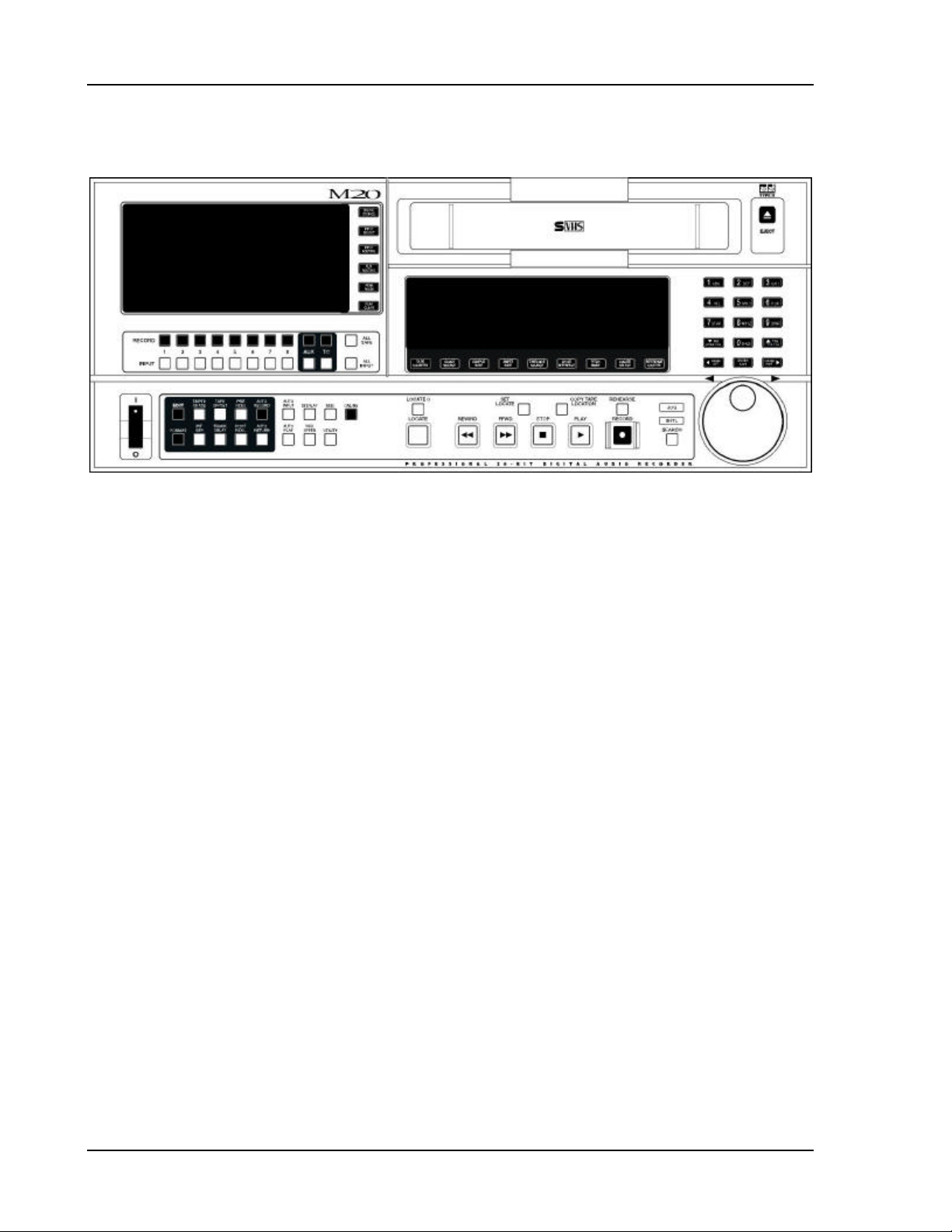
Figure 1 (M20 Front Panel)
1-6 ALESIS M20 REFERENCE MANUAL 1.06
Page 21

CONTROL AND CONNECTOR
2.1 ABOUT THE FRONT PANEL
Referring to Fig. 1, the front panel includes:
• S-VHS cassette door and Eject button
• Main vacuum fluorescent display (toward the center) with two sets of 10-character 7-
segment readouts. The left readout shows the current tape location. The right readout
shows information such as incoming SMPTE time, locate address, current offset, etc. A
24-character alphanumeric display above the 7-segment display shows edit location
points, pre/post-roll times, pitch value, and various messages.
• 9 function buttons (below the main display)
• 5 transport buttons
• 4 locate-related buttons
CHAPTER 2
BASICS
• Rehearse button
• Jog/shuttle wheel and search button
• 15-button numeric keypad for data entry
• 15 editing switches
• Secondary vacuum fluorescent display with VU meters for the 8 audio channels and
auxiliary track, the time code track signal, error lights, track input and record lights, and
input selection and routing indicators.
• 22 track enable and track record buttons
• 6 routing, source selection, and metering buttons
• Online/offline button
• Recessed power switch
ALESIS M20 REFERENCE MANUAL 1.06 2-1
Page 22
Control and Connector Basics, Chapter 2
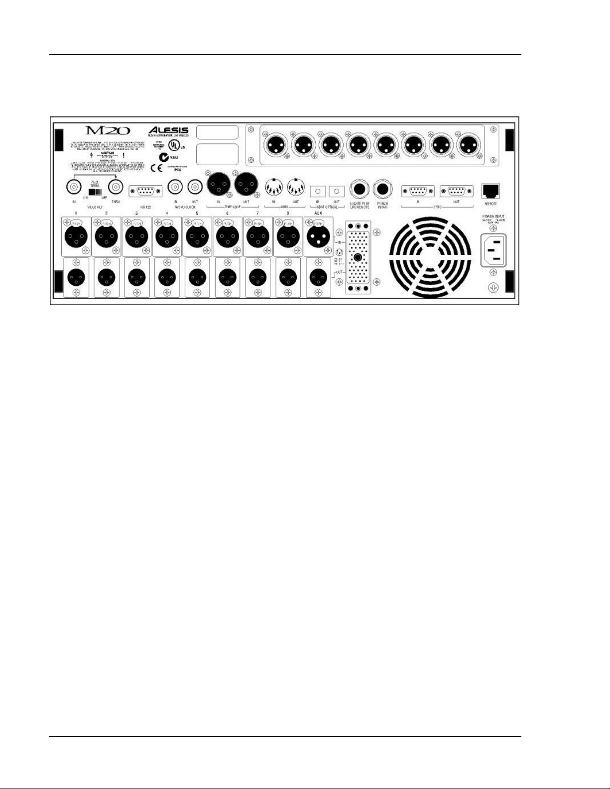
Figure 2 (M20 Rear Panel with optional EC-1 AES/EBU Card)
2-2 ALESIS M20 REFERENCE MANUAL 1.06
Page 23

2.2 ABOUT THE REAR PANEL
Referring to Fig. 2, the rear panel includes:
2.2A PUNCH FOOTSWITCH
This allows foot-controlled punch in and out. Use a momentary footswitch, either normallyopen or normally-closed (the M20 senses the type on power-up and calibrates itself).
2.2B LOCATE/PLAY OR LRC REMOTE CONTROL JACK
This 1/4” jack accepts a momentary footswitch (normally closed or open) to allow footcontrolled location functions. It also accepts the LRC remote control (see Chapter 14) for
remote access of transport functions.
Note: If using a normally open footswitch, the footswitch and LRC remote control can be
interchanged, or used simultaneously with a Y-cord, without restarting (powering
down and powering up) the M20. However, if using a normally closed footswitch,
the M20 unit should be restarted after switching from footswitch to remote control
and vice-versa.
Chapter 2, Control and Connector Basics
2.2C ANALOG INPUTS AND OUTPUTS
18 XLR connectors carry the +4 dBu balanced analog inputs and outputs. There are 9 audio
input and output channels (channels 1 through 8 plus Aux). Channels 1 through 8 inputs and
outputs are also accessible through a multi-pin ELCO connector, which is wired in parallel
with the XLR inputs and outputs. All XLR connectors are wired with pin 2 “hot,” in
accordance with IEC standards.
2.2D TIME CODE IN AND OUT
The time code input and output use balanced XLR connectors for use with SMPTE/EBU
standard time code systems. Time code input allows the M20 to be slaved to an external
device; time code output provides timing reference to an external device.
2.2E WORD CLOCK IN AND OUT
These are BNC connector, TTL-level word clock inputs and outputs. A master word clock
signal, which the M20 can provide, allows synchronizing the audio data stream for all digital
audio devices in a system. If a master word clock signal already exists, the M20 can sync to
it.
2.2F ADAT OPTICAL IN AND OUT
The optical input and output are an industry-standard digital audio interface, pioneered by
Alesis, that carries 8 digital audio channels (with up to 24 bits of resolution) on a single fiber
optic cable. The standard cable is a 1mm diameter plastic fiber with Toslink connectors. One
1-meter cable is provided with the M20; additional cables of different lengths are available
from your dealer. Applications include digitally dubbing from one deck to another,
interfacing with hard disk recording systems and synthesizers, and feeding translators that
change the ADAT optical format to other formats.
ALESIS M20 REFERENCE MANUAL 1.06 2-3
Page 24

Control and Connector Basics, Chapter 2
2.2G VIDEO IN AND THRU
The BNC connector video input (with 75 ohm termination switch) accepts composite video
as well as black burst video inputs.
2.2H ADAT SYNC IN AND OUT
These 9-pin D connectors synchronize multiple ADATs together to single-sample accuracy.
Computer interface cards with ADAT sync, such as the Alesis ADAT-PCR, allow
transferring ADAT data to and from a computer for editing with single-sample accuracy.
Interface cards without ADAT sync allow transferring ADAT data with 1/4 frame accuracy
via MIDI Time Code.
2.2I MIDI IN AND OUT
These 5-pin DIN connectors can output and/or receive MIDI Machine Control commands,
save and load sysex dumps defining the M20 status, allow for software updates via MIDI
sysex files, and output MTC (MIDI Time Code) when selected.
2.2J RS-422 IN (SONY 9-PIN)
This 9-pin D connector connects to a video editor or other controller that supports the Sony
9-pin protocol. This feature will not be operational until M20 Version 2.0 software becomes
available.
2.2K METER BRIDGE/REMOTE PANEL OUT
This RJ-45 connector connects to an optional remote controller like the Alesis CADI remote,
and/or RMD meter bridge.
2.2L POWER
The IEC-standard, grounded AC input plug accepts AC voltages from 90 to 250 volts,
eliminating the need for transformers or voltage switches.
2-4 ALESIS M20 REFERENCE MANUAL 1.06
Page 25

EDITING M20 OPERATING
3.1 THE KEYPAD
The keypad block contains switches for editing the various parameters that control the M20’s
features.
3.1A 0 THROUGH 9 BUTTONS
Use the 10 numeric keys to enter number parameter values and letters for names. When
editing a parameter value, pressing a key enters its associated number. When editing a name,
pressing a key cycles through the letters indicated on the keycap (e.g., pressing 7 repeatedly
cycles through 7, s, t, u, v, 7, s, t…etc.).
3.1B UP ARROW/YES/UPPER CASE
This key:
CHAPTER 3
PARAMETERS
• Increments parameter values, as well as scrolls up through a list of parameter values.
Holding this button for 2 or more seconds increases the speed at which the values
increment. After 7 seconds, this speed increases again.
• Enters “Yes” in response to Yes/No queries.
• In a sign (polarity) field, selects the positive (+) sign.
• In a name field, changes lower case letters to UPPER CASE.
3.1C DOWN ARROW/NO/LOWER CASE
This key:
• Decrements parameter values, as well as scrolls down through a list of parameter values.
Holding this button for 2 or more seconds increases the speed at which the values
decrement. After 7 seconds, this speed increases again.
• Enters “No” in response to Yes/No queries.
• In a sign (polarity) field, selects the negative (-) sign.
• In a name field, changes UPPER CASE letters to lower case.
3.1D CURSOR LEFT
When editing, this key positions the cursor (a single underline character, showing that a
parameter is ready for editing) under the next field to the left. (Note: It will not move across
page boundaries.)
3.1E CURSOR RIGHT
When editing, this key positions the cursor (a single underline character) under the next field
to the right. (Note: It will not move across page boundaries.)
ALESIS M20 REFERENCE MANUAL 1.06 3-1
Page 26

Editing M20 Parameters, Chapter 3
3.1F ENTER/NAME
This key has two main uses:
• Speed up numeric entry by eliminating the need for “leading zeroes.” For example, the
varispeed setting is a 3-digit value. Instead of having to key in something like 0 - 0 - 9,
you can simply key in 9, then press Enter.
• Edit location point names. When the locate time is the currently selected field, pressing
the Enter/Name button positions the cursor at the first character of the name. The cursor
buttons now select individual characters within the name field or other displayed fields;
use the keypad buttons to change the character. For upper case, use the Up Arrow. For
lower case, use the Down Arrow.
To exit the name field, press the Enter/Name button again.
Using the default name list instead of entering letters individually: An additional
name editing option is available. Holding down the Name button while using the
Up/Down buttons scrolls through a default set of 16 generic names (e.g., Verse 1,
Chorus, Bridge, etc.). This list may be customized for your working style.
To customize the default set of names:
1 Select the default name to be changed.
2 Edit it.
3 To store the new name in the default name list, hold the Enter/Name button and press
the Record button.
3-2 ALESIS M20 REFERENCE MANUAL 1.06
Page 27

Chapter 3, Editing M20 Parameters
3.1G SELECTING PAGES
Most buttons have at least one associated display page, which contains one or more
parameters. If there are multiple pages, the main display’s left side shows the current page
number; repeatedly pressing the associated button cycles through the pages.
Shortcut: To access a particular page directly, hold the associated button and use the keypad to enter
the desired single-digit page number.
Functions with double-digit page numbers (e.g., the Utility function) have a different access
procedure. Hold the current function button and press the 2 digits within 3 seconds of each
other. To select a single digit page number (1 through 9), press and hold the current function
button and either:
• Enter 0, then the digit; or
• Press the single digit, then the Enter button. (Note: If the Enter button is not pressed
within 3 seconds, the display reverts to its previous state.)
3.1H SELECTING PAGE PARAMETERS
To select the desired parameter for editing in multi-parameter pages, position the cursor
with the Left or Right Cursor button under the parameter value’s rightmost digit.
3.1I ENTERING PARAMETER VALUES
Entering complete values: Use the numeric keypad and enter the most significant digit first.
Enter all of a field’s digits to complete the entry. The cursor automatically advances through
the fields.
Increment/decrement a value by one: Use the keypad’s Up and Down buttons. Holding the Up
or Down button for more than 2 seconds increments (or decrements) the value continuously.
The value above the cursor will be changed. If the value goes beyond a boundary (for
example, increasing from 59 seconds to 0), the next field will be calculated automatically (in
this example, the minute field will be automatically increased).
ALESIS M20 REFERENCE MANUAL 1.06 3-3
Page 28

Editing M20 Parameters, Chapter 3
3.2 THE EDIT BUTTON
The Edit button toggles the M20 in and out of Edit Mode. Enabling Edit mode (button lit)
allows editing parameter values for the functions grouped with the Edit button: Track Delay,
Tape Offset, SMPTE Chase, Internal Gen, Format, Pre-Roll, Post-Roll, Auto Return, and Auto
Record. While Edit is On, only the currently selected function’s switch will light. However,
the M20 retains the current on/off status of all switches, and these become visible after
exiting Edit mode.
Note: Don’t be confused! Editing a function does not turn it on. For example, while
editing the Post Roll value the Post Roll switch will be lit, but if the light goes out
when you leave Edit mode, Post Roll is not yet active.
If the Edit LED is not lit, pressing the various switches toggles these functions on and off.
Example: If you’ve used the Edit button to edit the amount of Tape Offset and the Edit button
is off, turning on the Tape Offset button enables the programmed amount of offset.
Pressing the Display, Pitch Value, or Utility button will also exit Edit mode and enter the
Display, Pitch, or Utility pages, respectively.
3.3 EDITING CONVENTIONS
• The rightmost 7-segment display shows locate times in hours, minutes, seconds, frames,
subframes and samples. Subframes equal 1/100th of a frame and range from 0…99. The
number of samples per subframe depends on the Tape Counter and Sample Rate settings.
If the tape counter is in ABS Time mode, there are always 15 samples per subframe in 48
kHz and 14 per subframe at 44.1 kHz. If the counter is in a SMPTE Time Code mode and
the sample rate is 48 kHz, Sample steps range from 0 - 15 for 30 frames/sec, 0 - 15 or 16 for
29.97 frames/sec, 0 - 18 for 25 frames/sec, and 0 - 19 for 24 frames/sec.
• A lit arrow above the subframe (SF) indicator indicates that there is a non-zero sample
value. To access the samples field, with the subframe field selected press the Right
Cursor button. This selects a second page that shows only the sample value.
• When editing any tape address, the cursor steps in fields (hours, minutes, seconds,
frames, subframes, and samples) instead of stepping every digit.
• When editing any tape address, entering digits with the keypad automatically advances
the cursor or selected field (using the Up/Down Arrows does not advance the field)
• When editing a field in the 7-segment display, the digit(s) of the selected (and currently
editable) field will flash.
3-4 ALESIS M20 REFERENCE MANUAL 1.06
Page 29

CHAPTER 4
TAPE FORMATTING
Formatting is essential to the ADAT system. It creates a sample-accurate time reference (i.e.,
it’s accurate to 1/48,000th of a second when recording at 48 kHz) on each tape, in addition to
block ID codes, linear control track, and other essential markers. This provides tight
synchronization ó far better than SMPTE sync ó between ADAT-compatible devices, as well
as precision tape counter readings and intelligent autolocation functions.
The format process first records 15 seconds of leader (the display shows LEAd), followed by
two minutes of data (the display shows dAtA), then ABS time code starting at 00:00:00.00
and continuing to the end of the tape.
Caution: formatting a tape erases all material on all tracks. Always check that the tape is either blank
or contains unwanted material before formatting.
You can either:
• Format a tape completely before recording (recommended)
• Format while you are recording, for as long as needed
• Extend the format of an incompletely formatted tape
Before formatting a blank tape, you must select:
• The sample rate (44.1 or 48 kHz)
• The word length (20-bit for Type II tapes, or 16-bit for compatibility with Type I
ADAT and ADAT-XT tapes)
ALESIS M20 REFERENCE MANUAL 1.06 4-1
Page 30

Formatting Tape, Chapter 4
4.1 SAMPLE RATE SELECTION
Choose between 44.1 kHz (CD/consumer standard) or 48 kHz (DAT/professional standard).
Here are some general hints:
• If mixing the tape through a digital mixer for a CD master, use 44.1 kHz to avoid sample
rate conversion.
• If mixing the tape through an analog mixer, use 48 kHz for slightly better high frequency
response.
• If you plan to transfer M20 tracks over to a hard disk system for editing, note that audio
recorded at 48 kHz requires about 10% more storage capacity than the equivalent audio
recorded at 44.1 kHz.
The following sample rate selection procedure assumes that Clock Source is set to INTernal.
Operation You press… You see…
Select sample rate Sample Rate
button
Sample Rate block toggles between 44.1
or 48 kHz (default) with each Sample
Rate button press
About changing sample rates: The sample rate chosen during the format process does
not have to be used during playback or recording of that particular tape; the ADAT
format always allows you to override the default sample rate from the tape. When
loading a formatted tape, the sample rate will automatically switch to the tape’s
original settings. You may change the sample rate setting to playback or record with
a different sample rate, but the sample rate indicator will flash to indicate that it is
not at the original setting. Changing the sample rate directly affects the pitch and
speed of any audio recorded.
When extending a format, the sample rate will automatically assume the existing
format’s values. There is no way to format a tape with a “44.1” marker on one
section and a “48” marker on another.
4-2 ALESIS M20 REFERENCE MANUAL 1.06
Page 31

Chapter 4, Formatting Tape
4.1A PULL-UP AND PULL-DOWN SAMPLE RATE SELECTION
The Sample Rate button is also used to select the respective 0.1% pull-up and pull-down
rates. A pull-up is available with a 30 fps SMPTE rate only. A pull-down is available with a
29.97 fps SMPTE rate only.
Use pull-up or pull-down after a standard tape format: It is not necessary to pre-select
a pull-up or pull-down prior to formatting since the “pull” status is not recalled
when tapes are subsequently reinserted. Use the pull-up/pull-down feature after
formatting your tape. If you are formatting and recording simultaneously, using the
pull-up/pull-down feature may be appropriate.
Operation You press… You see…
Select a Pull-up
sample rate
Select a Pull-down
sample rate
Return to a normal
44.1/48 kHz sample
rate from a “pulled”
rate
…and hold
Sample Rate
button then press
Up button
…and hold
Sample Rate
button then press
Down button
…and hold
Sample Rate
button then press
the 0/Space
button
“+0.1%” displayed in the Sample Rate
block
“- 0.1%” displayed in the Sample Rate
block
Sample Rate block returns to normal
sample rate display (44.1 or 48 kHz)
Refer to section 16.4 for more information on pull-up and pull-down.
4.2 WORD LENGTH SELECTION
Select 20 bits unless you want compatibility with older, Type I format ADAT tapes.
Operation You press… You see…
Initiate word length
selection
Select word length Up or Down
Edit button, then
Format button
Arrow button so
that the display
shows…
Display says “Format Data Type” and
16 or 20 bits
The desired word length (16 or 20)
ALESIS M20 REFERENCE MANUAL 1.06 4-3
Page 32

Formatting Tape, Chapter 4
4.3 FORMAT A NEW TAPE
Use only S-VHS blank tapes formulated specifically for Super VHS video or digital audio
applications. Never use standard VHS tapes.
“Exercise” the tape: Before formatting, fast forward the tape to the end and rewind it to
even out the tape pack and sweep any contaminants off the tape.
Operation You press… You see…
Insert blank tape Tape into tape
chamber. Do this
gently; the
machine will
“grab” the tape
Enable formatting Format button
(with Edit button
off)
Initiate formatting Hold Record
then press Play
Display shows “noFO,” Format button
flashes
All record lights turn on
Display message advises you of
formatting progress
What happens between initiating formatting and the actual process of formatting depends on
the current tape status.
Tape status The M20…
Unformatted, at start of tape Begins formatting immediately
Unformatted, partway through tape Rewinds, then begins formatting
While rewinding from current position,
goes from unformatted to previously
formatted portion
Formatted, in Leader or Data section of
tape
Formatted, in Audio section of tape Extends format after entering record
Disables formatting to avoid reformatting a partially formatted tape.
Either extend the format from this
point on, or for a complete format,
rewind, then initiate formatting
Rewinds, then begins formatting
(see section 4.5 for information on
extending a format)
4.4 RECORD TRACKS WHILE FORMATTING
The procedure is similar to standard formatting, except:
• Record-enable (section 5.4) any tracks to be recorded prior to pressing the Format button.
• No audio will be recorded before the counter shows 00:00:00.00 ABS time.
4-4 ALESIS M20 REFERENCE MANUAL 1.06
Page 33

Chapter 4, Formatting Tape
4.5 EXTEND A PARTIALLY-FORMATTED TAPE
• The procedure is similar to standard formatting, except:
• Make sure the tape is located at least 20 seconds before the end of a previously-formatted
section before attempting to extend the format.
• Regardless of the current sample rate and word length, these will change automatically
to match the original format.
• After pressing the Format button, press and hold Play then press Record. Formatting
will begin when a lock is established.
Note: The above assumes the tape is somewhere after ABS time 00:00:00.00. If the tape to
be extended is in the leader or data sections (i.e., prior to ABS time 0:00:00.00),
entering Format mode automatically rewinds the tape to the leader and begins
reformatting. While rewinding, the display shows “…format begun” and the Rewind
button will light to remind you that the M20 must format over from the tape’s leader
and data sections.
4.6 END FORMATTING
When the tape reaches the end, formatting ends automatically and the tape will stop.
To stop formatting prior to the end-of-tape, press Stop. You cannot simply punch out with
the Play button.
4.7 CERTIFY TAPE FORMAT
After formatting, consider playing the tape through to the end to check for a suitably low
error count (see section 13.20), thus verifying the tape’s integrity.
4.8 REFORMATTING: CAUTION!
Do not stop in the middle of re-formatting over a previously formatted tape. When the tape
transitions from the newly formatted section to the previously formatted section, there will
be timing discontinuities, and you will not be able to record anything over the transition.
Either re-format the entire tape from beginning to end, or rewind a bit and extend the
existing format.
ALESIS M20 REFERENCE MANUAL 1.06 4-5
Page 34

Formatting Tape, Chapter 4
4.9 LOCK OUT FORMATTING (SAFE MODE)
You may lock out the format option to prevent accidental formatting. This remains in effect,
even if you insert different tapes, until the setting is changed. To lock out formatting:
Operation You press… You see…
Select safe function Edit button, then
Format button
until display
shows Page 2
(Format Safe)
Select format safe
status
Up or Down
Arrow button to
choose On or Off
respectively
Display says “Format Safe:” and
format safe status (on or off)
Selected format safe status
4.10 BULK ERASING
You can bulk-erase M20 tapes with a video tape eraser.
4.11 RECORDING A “BENCHMARK” TAPE
Alesis recommends that you format and record a new tape with any signal, such as a test
tone, in a single pass with no overdubs during the first week of operation. Store this tape in
a safe, dry location and don’t use it for any other purpose. Such a “benchmark” tape is useful
to determine if the error correction rate is increasing over time because the heads need to be
cleaned, or if a tape is defective.
4-6 ALESIS M20 REFERENCE MANUAL 1.06
Page 35

CHAPTER 5
TRACK RECORD ENABLING AND
MONITORING
5.1 TRACK BASICS
The M20 can record a total of 10 tracks:
• 8 digital audio tracks. These record standard audio signals, either from the analog
inputs, optional AES/EBU card, or ADAT Optical Interface.
• 1 analog Aux track. This track records audio information from the Aux input, along with
any of the eight audio tracks routed to the Aux track. This provides quality scrubbing
(which is difficult to do solely in the digital domain) and the ability to hear audio from
the Aux output during rewind, fast forward, and autolocate operations. During Search
operations, the Aux track can be routed to any of the eight standard audio track outputs
(see section 6.5).
• 1 time code track. This track records only SMPTE/EBU time code information, and
stores this data digitally on tape. It receives its input from the Time Code In jack if the
TC Source is set to External (section 11.3), or from the Internal Time Code Generator if
the TC Source is set to Internal.
SMPTE vs. ABS time code: The ADAT ABS time reference is separate from this SMPTE
time code track, and is written in a subcode of the tape automatically as part of the
format operation covered in Chapter 4.
To record, a track must first be record-enabled (see section 5.4; the record enable button light
will flash).
Aux and TC track record enabling: The Aux and TC tracks cannot be record enabled
simultaneously. For example, if the Aux track is record enabled and the TC Track
record enable button is pressed, record will disable on the Aux track and the TC
Track will become record enabled. This will occur in any transport mode, so if a
record is in progress on the TC Track, pressing the Aux track record enable button
will punch-out of the TC Track.
You typically press the Play and Record transport buttons to allow track-enabled tracks to
begin recording, although you can also use a footswitch (section 8.6e) and/or program
automatic punch in points (sections 8.8a and 8.8c). During recording, any armed Record
Enable buttons stay lit steadily.
ALESIS M20 REFERENCE MANUAL 1.06 5-1
Page 36

Track Record Enabling and Monitoring, Chapter 5
5.2 TRACK INPUT ENABLES
An input-enabled track monitors the associated input signal. There is one Input Enable
button (with associated indicator light) for each track (10 total). The Input Enable button
toggles between monitoring the input signal or monitoring the tape.
Operation You press… You see…
Enable track input
(monitors input signal)
Disable track input
(monitors tape signal)
The track Input Enable
button until…
The track Input Enable
button until…
5.3 AUTO INPUT SWITCH
This switch determines whether or not a record-enabled track (audio or aux) will monitor
from input or tape automatically, depending on the recording context. Disabling Auto Input
is preferred for recording basic tracks, while Auto Input is usually enabled during
overdubbing and punching.
Track input light turns
on
Track input light turns
off
What the tracks
monitor
Record-enabled
tracks monitor the…
Non-record-enabled
tracks monitor the…
5.4 RECORD ENABLE
Pressing a track’s Record Enable button allows it to record when the M20 is in Record mode.
Any number of channels can punch in simultaneously, or punch out simultaneously, and any
channel or channels can punch in or out while other channels are in record.
Operation You press… You see…
Record enable a track The track Record Enable
Turn off record enable
for a track
Punch in using Record
Enable button
Punch out using Record
Enable button
Auto Input
Off
Input signal Input while recording or stopped, tape
Tape Tape while playing or recording, input
button
The track Record Enable
button
While in Record mode
and the tape is running,
press Record Enable
button
While recording, press
Record Enable button
Auto Input On
while playing
signal when stopped
The Record Enable light
flashes, then lights solid
while recording
The Record Enable light
turns off
Record Enable button
lights solid
Record Enable button
turns off
If you press Play and Record with no tracks record-enabled, the Record light will flash
indicating a Record Pending mode. When the Record light is lit (or flashing if Rehearse is
enabled; see section 8.7), pressing individual track Record Enable buttons can punch
individual tracks in or out independently. The Record light will remain lit (or flashing in
Rehearse mode) until you punch out of Record, usually by pressing Play or any other
transport key.
5-2 ALESIS M20 REFERENCE MANUAL 1.06
Page 37

Chapter 5, Track Record Enabling and Monitoring
5.5 SAFETY MODE (ALL SAFE)
To prevent any accidental recording, pressing All Safe places all tracks (channels 1-8 plus
Aux and TC) into a safe (non-record ready) mode. This is particularly useful when mixing.
Operation You press… You see…
Place all tracks into a safe
(non-recordable) mode
Exit safe mode All Safe All track record ready
All Safe All track record ready
5.6 MONITOR INPUTS (ALL INPUT)
Pressing All Input sets all tracks, excluding the TC track, to monitor the input signal
regardless of the record-ready/auto-input status (section 5.3). Tape playback cannot be
heard while All Input is on. While enabled, the track input buttons will have no effect. This
is useful for live recording situations.
lights and auto-enabled
track input lights turn off
lights, and auto-enabled
track input lights return
to their state prior to
pressing All Safe
Operation You press… You see…
Have all tracks (except
TC) monitor the input
signal
Exit All Input mode All Input All Input Enable lights
This function can also be used while All Safe is on.
All Input All Input Enable lights
(except TC) are lit solid
return to their state prior
to pressing All Input
ALESIS M20 REFERENCE MANUAL 1.06 5-3
Page 38

Track Record Enabling and Monitoring, Chapter 5
5-4 ALESIS M20 REFERENCE MANUAL 1.06
Page 39

DIGITAL/ANALOG INPUT
SELECTION AND ROUTING
6.1 DIGITAL SOURCE
When using digital inputs, this function selects one of two or three digital input options. The
I/O card option will appear in the display only if an I/O card (such as the Alesis AES/EBU
card) is installed in the machine. Settings are retained in memory.
Operation You press… You see…
Select ADAT optical
digital input (default)
Select digital track copy
function
Select I/O card as the
digital input
The Digital Source button
until you see…
The Digital Source button
until you see…
The Digital Source button
until you see…
CHAPTER 6
ADAT optical in the Dig
Source block
Track Copy in the Dig
Source block
I/O card in the Dig
Source block
For more information on Track Copy, see section 6.4b.
6.2 INPUT SELECT
Not valid in Track Copy mode: If the Digital Source has been set to Track Copy, you
cannot enter Input Select mode. In Track Copy mode, only internal tape tracks may
be recorded.
Inputs can come from digital or analog signal sources. Use the Input Select button to choose
digital or analog inputs as the signal source for each adjacent track pair (1/2, 3/4, 5/6, or
7/8). In addition, all tracks may be set to receive analog or digital.
If no track buttons are pressed within 10 seconds of entering Input Select mode, the M20
automatically exits.
Operation You press… You see…
Enter Input Select mode The Input Select button Input Select display
Select analog or digital
input source
Select all channels for
digital input
Select all channels for
analog input (default)
Exit Input Select mode The Input Select button Input Select indicator
indicator flashes
Either Track Input button
of a stereo pair to toggle
between analog or digital
source for the track pair
The All Input button A and D indicators all
The All Safe button A and D indicators all
A and D indicators at the
base of the VU meters
indicate analog or digital
input, respectively
show D
show A
turns off to confirm the
exit
ALESIS M20 REFERENCE MANUAL 1.06 6-1
Page 40

Input Selection and Routing, Chapter 6
If no digital signal input is detected, the D indicators for the channel(s) without a digital
signal source will flash until signal is detected.
6.3 TRACK OUTPUT SELECTION
It is not necessary to select an output destination. Audio data always appears simultaneously
at the analog, ADAT optical, and optional AES/EBU outputs. Audio always appears at the
same-numbered output it was recorded on.
6.4 INPUT SIGNAL ROUTING (ANALOG AND DIGITAL)
The Input Route button selects how the M20’s analog and digital inputs are routed to the 8
tape channels. If no track buttons are pressed within 10 seconds of entering Input Route
Mode, the M20 automatically exits.
Operation You press… You see…
Enter Analog Routing
page (available only if at
least one track pair’s
input has been set to “A”
using Input Select mode)
Choose Analog Routing Input (white button
Enter Digital Routing
page (available only if at
least one track pair’s
input has been set to “D”
using Input Select mode)
Choose Digital Routing See section 6.4b See Section 6.4b
Exit Input Routing mode Press the Input Routing
The Input Routing button Every track’s A indicator
lights, display says
“Select analog input trks”
Odd/Even lights tracks 1
below record) for Track 1
or 2 to select Odd/Even,
Track 3 or 4 to select Half
& Half, Track 5, 6, 7, or 8
to select One-to-One
(default; see diagram
below)
The Input Routing button
again (or press twice if
not already in Input
Route mode)
button until the Input
Route indicator turns off
&2, Half & Half lights
tracks 1—4, One-to-One
lights tracks 1—8
Every track whose Input
Select is set to Digital’s D
indicator lights, display
says “Select optical src
trks” or “Select I/O card
src trks”
Channel indicators and
track select buttons
return to their normal
status
Analog and Digital Routing not available in Track Copy mode: If the Digital Source
has been set to Track Copy, Input Routing sets which internal tape tracks will be
copied (see 6.4b).
6-2 ALESIS M20 REFERENCE MANUAL 1.06
Page 41

Chapter 6, Input Selection and Routing
6.4A ANALOG INPUT ROUTING
The three analog routing modes accommodate 2, 4, or 8 bus mixing consoles. With two
buses, connect them to inputs 1 and 2. With four buses, connect them to inputs 1 through 4.
With 8 buses, direct outs or a patch bay, run each bus out to its like-numbered M20 input.
The analog routing choices are:
• Odd/Even: Press either the Track 1 or 2 button. Input 1 feeds channels 1, 3, 5, 7, and
Input 2 feeds channels 2, 4, 6, 8. To record on an odd-numbered track, route the
signal(s) to bus #1 or left. To record onto an even-numbered track, route the signal(s)
to bus #2 or right. By simply putting the desired track into record, the proper signal
will get there, even though it is not connected directly to the track’s input jack.
• Half & Half: Press either the Track 3 or 4 button. Input 1 feeds channels 1, 5; input 2
feeds 2, 6; input 3 feeds 3, 7; input 4 feeds 4, 8). To record on tracks 1 or 5, route the
signal(s) to bus #1. Likewise, to record onto tracks 2 or 6, route the signal(s) to bus
#2, and so on.
• One-to-one: Press either the Track 5, 6, 7, or 8 button in Input Routing mode. This is
the power-on default, where each input feeds its corresponding channel. To record
on track 1, send the signal to mixer bus 1, to record on track 2 send the signal to
mixer bus 2, etc. This is also the recommended mode when feeding the M20 from a
mixer channels’ direct outs.
Alternate method: In Input Routing mode for analog inputs, the All Safe button selects
the odd/even configuration and the All Input button selects one-to-one.
ALESIS M20 REFERENCE MANUAL 1.06 6-3
Page 42

Input Selection and Routing, Chapter 6
6.4B DIGITAL INPUT ROUTING
The Digital Source setting (section 6.1) influences the digital input routing process. This
feature makes it possible to record incoming digital data on any track desired, without
manually repatching.
If digital source = ADAT Optical:
Any of the 8 incoming optical channels may be individually selected or de-selected with the
Track Input buttons while in Digital Routing mode.
• A lit track input light indicates that the incoming ADAT optical channel is a digital
source.
• If a track input light is dark, that means the incoming ADAT optical channel will be
skipped as a source.
• Pressing the All Input button selects all eight channels as optical sources (this is the
normal state).
• Pressing All Safe turns off all channels, which results in a one-to-one routing (just as
if all 8 channels were selected as sources). All Safe simply “clears the slate” for
additional digital source channel selections.
If digital source = I/O Card (AES/EBU):
Because AES/EBU is a 2-channel digital format, only channel pairs (1-2, 1-4, or 1-8) may be
selected or de-selected. Pressing the All Input button selects all channels. As in ADAT
Optical, a lit track input light indicates that the channel is a digital source.
If digital source = Track Copy:
Any of the 8 channels, to a maximum of 4 total, may be individually selected or de-selected.
A lit track input light indicates that the channel is a track copy source, i.e., the selected
channels are the internal source channels eligible for digital bouncing within a single M20.
Pressing the All Input button selects channels 1 through 4 as track copy sources.
• No more than 4 tracks may be copied within a single machine, so if 4 source tracks
are already selected, one must be de-selected before you can select another track.
• A digital source track cannot be record-enabled in Track Copy mode. If you try, the
message “Source cannot equal dest” will appear in the display.
• When copying tracks, any track delays (section 11.9) will be in effect.
• Pressing All Safe deselects any track copy source channels.
6-4 ALESIS M20 REFERENCE MANUAL 1.06
Page 43

Chapter 6, Input Selection and Routing
6.4C RECORD-ENABLING THE DESTINATION TRACKS
In Digital Routing mode, inputs need not be routed only to same-numbered tracks. Any
selected digital source inputs can be re-routed to any record-enabled destination tape tracks,
in ascending order.
Example: if ADAT optical source inputs 1 and 5 are selected using Input Routing, and
tracks 3 and 4 have digital sources (“D” selected as Input Select) and are recordenabled, then incoming digital audio on optical channel 1 goes to track 3, and
incoming digital audio on input 5 feeds track 4.
If more destination tracks are enabled than there are source inputs, the source inputs will
repeat (cycle). Note that this technique allows copying a single incoming signal to multiple
tracks.
Example: if in the previous example tracks 7 and 8 were record-enabled as well as tracks
3 and 4, audio from input 1 would go to tracks 3 and 7, and incoming audio from
input 5 would feed tracks 4 and 8.
If all 8 source tracks are selected, then no digital routing occurs as this gives a one-to-one
relationship (the power-on default).
Example: if all eight ADAT optical sources are selected, and tracks 3 and 4 are record-
enabled, they will receive digital audio from ADAT optical channels 3 and 4
respectively.
The track copy function works the same way. If Digital Source is set to Track Copy and
tracks 7 and 8 are the only tracks selected in Input Routing mode, track 7 will be copied on
the lowest-armed track and track 8 will be copied onto the next higher armed track. For
example, if tracks 2, 4, 5 and 6 are armed, track 7’s data will be copied onto tracks 2 and 5
and track 8 onto tracks 4 and 6.
ALESIS M20 REFERENCE MANUAL 1.06 6-5
Page 44

Input Selection and Routing, Chapter 6
6.5 AUX ROUTING (INPUT AND OUTPUT)
The analog Aux track of the M20 is a unique feature that has special application in Search
mode, because it allows you to hear audio at extremely slow speeds for cueing. The Aux
Routing feature allows you to automatically mix other tracks for recording onto this track.
The back panel Aux Input is permanently routed to the Aux track. The Aux Routing button
selects whether additional inputs will also feed the Aux track (e.g., if tracks 1 and 6 are routed
to the Aux track, then the Aux track will record tracks 1 and 6 and the Aux Input). You can
route any track or group of tracks to the Aux track. If no track buttons are pressed within 10
seconds of entering Aux Route mode, the M20 automatically exits this mode.
It is also possible to automatically record a copy of whatever tracks are currently armed onto
the aux track, so the Aux track always contains the last overdub only. This is called “Auto”
mode.
Operation You press… You see…
Enter Aux Route mode The Aux Routing button Aux Route indicator
Select Aux tracks
manually
Select Aux tracks
automatically (this
directs all record-enabled
tracks to the Aux track)
Exit Aux Route mode The Aux Route button, or
The desired channels’
Track Input buttons
Aux Input button (white
button above Aux Rec
Enable)
wait 10 seconds without
pressing any buttons
flashes
Aux indicator (below VU
meter for each selected
track input) lights
“Auto” indicator below
the Aux track input
lights; any individual
track “Aux” indicators
disappear
Aux Route indicator
turns off; channel
indicators and track
select buttons return to
their normal status
Aux routing takes effect only after Record: The routing to the Aux track changes only
upon entering Record mode. Thus, even with Auto Routing enabled, the current
manual or previous auto routing remains in effect until the Aux track goes into
record.
Aux output routing: When in Jog/Shuttle mode (section 8.4), the Aux output routing
always follows the input routing. Example: If tracks 1 and 5 are routed to the Aux
track, then the Aux track output (which sums tracks 1 and 5 and feeds them to the
Aux Out) will appear on both outputs 1 and 5, unless tracks 1 and 5 are selected as
inputs. This makes it unnecessary to keep a channel on the console dedicated to the
Aux output.
If you turn off Auto mode (press Aux Routing, then press the Aux Input button), the Aux
routing tracks do not return to what had been selected manually prior to automatic Aux
selection; they will show the tracks last armed and recorded.
6-6 ALESIS M20 REFERENCE MANUAL 1.06
Page 45

With digital recording, it is very important not to exceed the available headroom (and with
20 bits to play with, you have so much dynamic range that there’s no need to push it). The
M20 provides three different metering modes to make it easier to avoid overloads.
7.1 METER MODE SELECTION
The Peak Mode button cycles through three different meter modes:
• No Peak Hold. Meter levels reflect the current input signal levels.
• Momentary Peak Hold (default). Although the meter reflects the current input
signal, the meter also retains the peak level briefly. This is useful if the signal to be
recorded has short transients, which you might miss seeing when they occur.
• Continuous Peak Hold. The meter also reflects the current input signal, but retains
the highest peak until cleared. Thus, if you can’t monitor a track continuously during
the recording process, you can look at the meter after the recording is over to see the
highest recorded peak.
CHAPTER 7
METERING
As you cycle through these options, the main display briefly shows the selected mode.
7.1A CLEARING PEAKS
With continuous peak hold, you will eventually want to clear the peak level indicators on all
8 channels. Press Peak Clear to reset the meters.
ALESIS M20 REFERENCE MANUAL 1.06 7-1
Page 46

Metering, Chapter 7
7.2 METER SETUP
The VU meter scaling, headroom, decay time, and peak hold time are all adjustable using the
Display menus. The Display button is in the lower left group of buttons beneath the meter
display.
Scaling determines whether the meter range is -72 dB to 0 (Normal; this is the default) or -2.0
to +2.0 (Fine).
Headroom sets the headroom amount for the Fine VU meter mode (it does not affect the
normal mode) by letting you specify what value the 0 dB marking represents. The value
ranges from 2 to 22 dB, in 1 dB steps (default = 15 dB).
Decay sets the time for a meter segment to turn off after the signal goes below that level, with
a range of 1 to 99. Each step represents 5 milliseconds, with higher numbers standing for
longer decays. The maximum decay of 99 means a segment will hold for 500 ms. (1/2
second). Default = 10.
Peak hold time sets how long peaks will be held when the meters are in momentary Peak
Hold mode, from 1 to 99. Each step represents 250 milliseconds, with higher numbers
standing for longer holds. The maximum decay of 99 means a segment will hold for
24.75 seconds after level has fallen. Default = 8
Operation You press… You see…
Enter VU meter scaling
setup
Edit VU meter scaling Up/Down buttons Display shows Normal
Enter VU meter
headroom page
Edit VU meter headroom Keypad or Up/Down
Enter VU meter decay
page
Edit VU meter decay Keypad or Up/Down
Enter VU peak hold page Display button again Display says VU Peak
Edit VU peak hold Keypad or Up/Down
Display button Display says VU Meter
Scale
or Fine scaling
Display button again Display says Fine
Headroom
Display shows amount of
buttons to choose the
headroom amount
Display button again Display says VU Decay
buttons to choose the
amount of decay
buttons to choose the
peak hold time
Fine headroom in dB
Display shows amount of
meter decay time
Hold
Display shows amount of
peak hold time
7-2 ALESIS M20 REFERENCE MANUAL 1.06
Page 47

TRANSPORT CONTROLS AND
BASIC RECORDING
The transport buttons include Rewind, Fast Forward, Stop, Play, Record, and Eject. The
transport movement may also be controlled by the jog/shuttle wheel, or various built-in
automatic features.
8.1 ABOUT THE TAPE COUNTER
The tape counter, located on the right side of the right display, shows the current tape
location. The Tape Counter button selects the counter mode (the 10-digit location counter is
above the Tape Counter switch). Pushing the switch cycles through three different modes.
• ABS Time references the current tape location to the proprietary sample-accurate
ADAT time code formatted into each ADAT tape.
• Relative references the current tape location to the relative zero location. The
relative zero point is set by entering an absolute time value into the Locate 00
address. That value is subtracted from the absolute time code value when the tape
counter display is in Relative mode.
CHAPTER 8
• SMPTE references the current tape location to SMPTE (i.e., ABS + any SMPTE offset,
Note: this is NOT necessarily the SMPTE time code printed onto the T/C track. That
8.2 STOP
Press to stop the tape transport (Stop button lights steadily). The tape stops moving, but
remains threaded around the head drum.
The tape will unthread (i.e., disengage from the head drum) automatically if no transport
movement occurs during a user-definable timeout period (default = 4 minutes; see section
13.9). Stop will flash. To re-thread the tape, press Stop again (it lights steadily). Note that
entering play from the unthreaded position takes slightly longer than when the tape is
already threaded, due to the time required to wrap the tape around the head drum.
as described in section 11.6a).
code is displayed in the Reference counter on the left side of the display.
ALESIS M20 REFERENCE MANUAL 1.06 8-1
Page 48

Transport Controls and Basic Recording, Chapter 8
8.3 PLAY
How Play affects tape motion depends on the tape’s status.
If the tape
is…
Stopped Playback Play button lights steadily
Playing No change (playback continues) Play button lights steadily
Formatting No change (formatting continues) Play button lights steadily
Locating Playback after the locate is
Locating Pressing Play twice stops
Recording Punch out, and enter Play Play button lights steadily
Pressing Play causes… You see…
complete
autolocation and begins playback
8.3A PLAY BUTTON AND SYNC STATUS
When the M20 is playing and in sync, the Locked indicator (under the last field of the tape
counter) will light solid.
If the M20 loses sync while playing (either as a master or as a slave), the Locked indicator
will turn off.
8.4 JOG/SHUTTLE WHEEL AND SEARCH
The jog/shuttle wheel provides convenient access to capstan-engaged rewind, fast forward,
and “scrub” functions (in scrub mode, audio normally comes from the analog Aux track). In
master/slave situations, the master’s jog/shuttle wheel controls the slaves, regardless of the
slave’s physical wheel position.
Play light flashes during
locate, then stays lit when
locate is complete
Play button lights steadily
Pushing the Jog/Shuttle wheel selects between the two modes, as indicated by LEDs above
the Search button. The Search button works with the Jog/Shuttle wheel, as described toward
the end of this section.
8.4A JOG MODE
Jog advances or rewinds the tape at a rate proportional to thespeed of wheel rotation. This
allows you to move the tape as if you were “rocking the reels” on a n analog machine.
Action… Result… You see…
Turn wheel
clockwise
Turn wheel
counterclockwise
When in Jog mode and the transport is idle, the Search and Play buttons will remain lit, and
the Stop button will light steadily (indicating that jogging is paused).
Tape moves forward at a rate
proportional to rotation
speed (1/8X to 1X play
speed)
Tape move in reverse at a
rate proportional to rotation
speed (1/8X to 1X play
speed)
The Search and Play buttons
light, and right arrow above
wheel lights
The Search and Play buttons
light, and left arrow above
wheel lights
8-2 ALESIS M20 REFERENCE MANUAL 1.06
Page 49

Chapter 8, Transport Controls and Basic Recording
8.4B SHUTTLE MODE
Shuttle advances or rewinds the tape at a rate proportional to the degree of wheel rotation.
The greater the degree of rotation from the center detent, the faster the rate.
Action… Result… You see…
Turn wheel
clockwise
Turn wheel
counterclockwise
Push lit Search
button while in
Shuttle mode
Tape moves forward at a
rate determined by amount
of rotation (from 1/4X to 16X
play speed)
Tape moves in reverse at a
rate determined by amount
of rotation (from 1/4X to 16X
play speed)
Transport goes into Play Search and Transport Stop
The Search and Play buttons
light, and right arrow above
wheel lights
The Search and Play buttons
light, and left arrow above
wheel lights
buttons goes out, Play
remains illuminated
8.4C SEARCH BUTTON
The Search button toggles transport control between the Jog/Shuttle wheel (Search button lit)
and the transport buttons (Search button dark), making it easy to go in and out of Play mode
while using the Jog or Shuttle function to locate a specific piece of audio.
Action… Result… You see…
Push lit Search
button while in
Jog or Shuttle
mode (disable
Search mode)
Push unlit Search
button while in
Jog or Shuttle
mode (enable
Search mode)
Search mode can be initiated simply by turning the jog/shuttle wheel, or enabled only by
pressing the search button, according to the settings on Page 10 in the Utility menu (section
13.10).
Transport goes into Play Search and Transport Stop
buttons go out, Play remains
illuminated
Transport enters jog/shuttle
mode:
If in Jog mode, stops;
If in Shuttle mode, moves in
the direction and speed
indicated
Search and Transport Stop
buttons light, Play remains
illuminated
Direction arrows may be lit
in Shuttle mode
ALESIS M20 REFERENCE MANUAL 1.06 8-3
Page 50

Transport Controls and Basic Recording, Chapter 8
8.4D SEARCH MASTER
This function (available only in the ID 1 master M20 in a system) accommodates situations
where you want to use jog on a machine that is not the master (e.g., to find a particular point
on the tape of a slave ADAT only). In this case, you don’t want the slave M20 to follow the
master, but instead, to act as a “temporary locate master” so all machines (including the ID 1
master) park where the designated search master machine parks after a jog or shuttle
operation. The default Search Master machine is ID1. Search Master status is not retained
when the power goes off.
To set which online M20 controls the parking address for all other M20s in a system:
1. Press and hold Search for 2 seconds to enter Search Master Edit mode. The display
shows “Search Master: n” (n = 1 — 8 or All).
2. While continuing to hold Search, use the numeric keypad buttons (1-8, 0) or Up/Down
buttons to select a search master (default is 1). Releasing the Search button exits the edit
mode without changing the Search mode status.
Selecting a machine other than ID 1 as a search master and activating Search mode (Jogging
or Shuttling) causes the display to indicate momentarily “Machine n Search Master” (n = 1 -
8) or “No Search Master” when All is selected. If you pause a search, ID 1 will query the
search master, update ID 1’s tape counter, and locate all connected machines to the position
of the designated search master.
When search master equals All, ID 1 will not send a locate command to the slaves. All decks
will remain parked after a search.
Releasing the Search button exits Search Master Edit mode, and the M20 reverts to the
display prior to selecting the Search Master.
Note: ID1 must remain online, and the user must observe the time code display when
actively jogging or shuttling because when a slave is the search master, the master’s
tape counter display will only reflect ID1’s tape position until Search mode is paused
and ID1 has located to the search master’s tape position.
8-4 ALESIS M20 REFERENCE MANUAL 1.06
Page 51

Chapter 8, Transport Controls and Basic Recording
8.5 OTHER TRANSPORT BUTTONS
You press… If tape is
stopped
Eject Tape ejects Tape stops
Eject on Master
deck (ID 1)
Hold Peak
Clear while
pressing Eject
Rewind Tape begins
Rewind + Play
(Review mode)
Fast Forward Tape fast
Fast Forward +
Play (Cue
mode)
Master and
slave tapes eject
Master tape
only ejects,
MMC Stop
command is
sent to slaves
rewinding at
16X play
speed,then
accelerates to
85X play speed
Tape rewinds
at 3X real time
and plays
pieces of audio
forwards at 16X
play speed,
then accelerates
to 85X play
speed
Tape fast
forwards at 3X
real time and
plays pieces of
audio
If tape is moving You see…
prior to ejection
Tape stops
prior to ejection
Master tape
ejects, MMC
Stop command
is sent to slaves
Same Rewind button lights
Same, except if
recording,
punches out
first
Same Fast Forward button
Same, except if
recording,
punches out
first
Tape exits cassette
well, eject button lights
Tape exits master and
slave cassette wells,
eject button lights
Tape exits master
cassette well, eject
button lights
steadily
Play button lights
steadily, Rewind light
flashes
lights steadily
Play button lights
steadily, Fast Forward
light flashes
To end a Cue or Review operation, press Play, Stop, Rewind, Fast Forward, or Search.
ALESIS M20 REFERENCE MANUAL 1.06 8-5
Page 52

Transport Controls and Basic Recording, Chapter 8
8.6 RECORD
This button’s operation depends on whether One-Button Record (section 13.4) is enabled or
disabled.
You press… If tape is
stopped
Record, and
while holding,
press Play
Record Recording
If the Format light is lit, entering Record mode will format the tape (see Chapter 4 on
formatting).
Recording
begins
begins
If tape is moving You see…
Recording
begins
No change in
existing status
Record button lights
If recording, record
button lights
8.6A PUNCHING INTO RECORD
There are five ways to punch into record while the tape is playing.
• Press and hold Record, then press Play at the punch-in point (or vice versa).
• With One-Button Record enabled, press Record at the punch-in point.
• Use the Record Enable buttons for enabled source inputs. If no tracks are record-enabled
and you press Play and Record, the Record button will flash to indicate Record mode is
pending. At the punch-in point, press the appropriate Record Enable buttons (dynamic
punch, section 13.13, must be enabled for this function to work).
• Use a footswitch (section 8.6e).
• Program Auto Record (section 8.8).
8.6B PUNCHING OUT OF RECORD
There are five ways to punch out of record.
• Press Stop. The transport punches out of record, then stops.
• Press and hold Record, then press Play.
• Press Play.
• Use the footswitch (section 8.6e).
• Turn off a track’s Record Enable button (dynamic punch, section 13.13, must be enabled
for this function to work).
8-6 ALESIS M20 REFERENCE MANUAL 1.06
Page 53

Chapter 8, Transport Controls and Basic Recording
8.6C RECORD WRITE-PROTECTION
S-VHS cassettes have a write-protect tab on the side of the tape opposite the “door” that,
when removed to create a small “window,” prevents recording. The M20 senses the writeprotect tab status. If the tape is write-protected, the M20 will not allow recording or
formatting to take place. Attempting to record causes the display to show “ERROR - Write
Protected,” and the transport will enter or remain in play.
How to Override Write-Protection
It is possible to record on a tape that has been write-protected (without resorting to the usual
tactic of taping over the tab). A tape must be in the transport to perform this procedure:
Operation You press… You see…
Enable write-protect
override
Disable write-protect
override
Sense Write Protect auto-reset: Write-protect override resets to the default “Sense Write
Protect” status automatically whenever the tape is ejected.
Press and hold Peak
Clear, then press
transport Record button
Press and hold Peak
Clear, then press
transport Record button
Display says “Override
Write Protect”
Display says “Sense
Write Protect”
8.6D RECORDING WITH A FOOTSWITCH
If any tracks are record-enabled and the tape is playing, pressing the punch footswitch is
equivalent to pressing Record and Play.
If the M20 is already recording, pressing the punch footswitch exits Record mode but the
transport continues to play.
If you plug in a footswitch while the M20 is on, turn the M20 off and then on again so the
machine can sense whether the momentary footswitch is a normally open or normally closed
type.
Note: Footswitch-controlled recording also works in conjunction with Rehearse mode (section 8.7) and
Auto Record mode (section 8.8).
8.7 REHEARSE MODE
Rehearse mode allows checking punch point accuracy without actually entering Record
mode. Record-enabled tracks will switch from tape monitor to input monitor at the punch-in
point, and back to tape monitor at the punch-out point.
Operation You press… You see…
Enable Rehearse mode Rehearse button Rehearse switch lights,
Disable Rehearse mode Rehearse button Rehearse switch light
Record light flashes (not
lit solid) while rehearsing
the punch
turns off
ALESIS M20 REFERENCE MANUAL 1.06 8-7
Page 54

Transport Controls and Basic Recording, Chapter 8
8.8 AUTO RECORD
In Auto Record mode, you can program punch in and out points. Pressing Play and Record
prior to the punch-in point causes the M20 to automatically punch in and out at the
programmed points.
You first must set auto-punch points, then enable the function. The auto-punch in and out
points default to autolocation points 98 and 99 respectively. These points automatically store
the locations of the last manual punch in and out, so anytime you have gone into record
manually you can repeat that punch exactly using Auto Record mode if desired.
If the auto punch-out location address is lower than the punch-in address, the Auto Record function
will be disabled (light off), and attempting to enable this causes an error message in the display.
8.8A SETTING AUTO RECORD PUNCH POINTS
To edit the auto record in and out points (as displayed in the right side of the main display),
follow the steps below.
Operation You press… You see…
Display punch in or out
point
Choose specific location
as punch in or punch out
point
Edit punch in or punch
out point
Disable punch out point Both Up and Down
Exit Auto Record setup Press Edit button Display returns to
Edit button followed by
the Auto Record button
(Auto Record toggles
between displaying
punch in and punch out
points)
Up/Down buttons Display shows new
Cursor buttons, then
enter numbers (keypad,
Up/Down buttons, Copy
Tape Location) in the
appropriate fields
buttons simultaneously
(cursor must not be in a
time field)
Display shows punch in
or out point
punch in or punch out
point
Field to be edited
flashing, then replaced
by your entry
Display shows Out Pt
Disabled
normal
8-8 ALESIS M20 REFERENCE MANUAL 1.06
Page 55

Chapter 8, Transport Controls and Basic Recording
8.8B ENABLE AUTO RECORD
To enable and disable Auto Punch, make sure the machine is not in Edit mode (if necessary,
press the Edit button so that it turns off).
Operation You press… You see…
Enable Auto Record Auto Record button Auto Record button
lights
Disable Auto Record Auto Record button Auto Record button
turns off
Use Auto Record Press Play and Record
prior to the punch in
point
Note: If the currently selected locate number equals the punch-in locate number, then the In label
lights in the Locate Point block. Similarly, if the currently selected locate number equals the punch-out
locate number, then the Out label lights in the Locate Point block.
Record buttons light
solid during punched
region
8.8C SET AUTO PUNCH POINTS “ON THE FLY”
Whenever you punch in/out manually (as opposed to auto-record), the default auto-punch
points assume the times of the manual punch points, and stores them in locations 98 and 99.
Note: This is not the case if punching is enabled/disabled with the Record Enable buttons.
ALESIS M20 REFERENCE MANUAL 1.06 8-9
Page 56

Transport Controls and Basic Recording, Chapter 8
8-10 ALESIS M20 REFERENCE MANUAL 1.06
Page 57

CHAPTER 9
AUTOLOCATION
The M20 can autolocate to specific points on the tape. Its built-in memory contains 100
different location points, complete with 8-character names. Locate points are used not only
for convenience, but in several other functions of the M20 such as Auto Record and Tape
Offset. These points are saved in the memory of the M20 even when power is turned off,
and may even be saved to the data header of each tape or to a MIDI file via a sysex dump.
The Locate button is positioned next to the other transport buttons (left of the Rewind
button). The currently chosen point is shown in the lower right corner of the main display.
Normally, the upper line of the display shows the location number and name.
Tip: Most M20 users find it convenient to leave the display in Locate Select mode, and
the reference counter in Locate Point mode. If a Display, MIDI, Vari Speed, or Utility
button (these are grouped next to the green Online button) are pressed, they will take
over the top line of the main display, and their button will light. Press Locate Select
to return the display to its default state.
The Locate Point display uses the ADAT’s ABS time as a reference, not the SMPTE time code
track. It can, however, display locate points in SMPTE, Absolute, or Relative modes. If the
Tape Counter (lower left counter in the main display) is in SMPTE, it uses the fixed SMPTE
offset (set in the SMPTE Chase menu) to calculate its value. If the Tape Counter is in Relative
mode, it will subtract the Locate 00 number to calculate its value.
9.1 ENTERING, SELECTING, AND EDITING LOCATION
POINTS
9.1A S
ET LOCATE
Pressing the Set Locate button (located just above the Stop button) at any time stores the
current tape location (rounded to the nearest subframe) into the next memory location for
later recall. If the Location point is currently 00, the first press of Set Locate stores the
current ABS time into Locate point 01 (shown in the display lower right). The next locate
point is 02, the next 03, and so on up to a maximum of 97. Any previous location address,
but not its name, will be overwritten when using Set Locate. The location block also
indicates whether the location point is one of four special locations (In, Out, Start, or End).
Note: Set Locate will not increment to points 98 and 99, as these are reserved for punch points set
manually. You must select these points with the Up/Down Arrow buttons to update them with the Set
Locate function.
9.1B COPY TAPE LOCATION
Pressing the Copy Tape Location button stores the current tape location from the tape
counter to the currently-showing locate point indicator; this function is useful for grabbing
location points “on the fly,” as well as for manual auto-punch and loop points. Unlike Set
Locate, doing this does not increment to the next location point number. You must increment
manually.
ALESIS M20 REFERENCE MANUAL 1.06 9-1
Page 58

Autolocation, Chapter 9
To select and edit location points:
Operation You press… You see…
Copy Tape Location to
memory
Store Locate Point Set Locate button Locate Point display
Select Locate Point Locate Select button, then
Edit Locate Point Locate Select button, then
Edit Locate Name Locate Select button, then
Go to Locate Point After selecting the
Locate to Zero* Locate 0 button The Rewind or Fast
Copy Tape Location
button
Up/Down Arrows or
number keys to select the
desired location point
press Cursor Left/Right
to select the field to be
edited (it will flash). Use
Up/Down Arrows, or
number keys to enter the
new value
Enter/Name button.
Enter the name.
desired Locate Point
(using Select Locate
mode), press Locate.
Tape counter time
(display left side) is
copied to the Locate
Point indicator on the
display’s right side
(Reference Counter).
shows the current time;
the location block shows
the locate point number
Locate Select display
shows the location point
number and name; the
locate point block shows
the locate point number;
Reference Counter (if in
Locate Pt mode) shows
the point time.
Locate Point display
(Reference Counter)
shows the location point
time; the locate point
block shows the locate
point number
Locate point block shows
the locate point number
The Rewind or Fast
Forward button flashes
to indicate the direction
of the search. The Locate
button stays lit until the
tape reaches its
destination.
Forward button flashes
to indicate the direction
of the search. Locate 0
lights stays lit until the
tape reaches its
destination.
*Whether the tape counter display is ABS (Absolute), Relative, or SMPTE, the zero point is
always at ABS 00:00:00:00 (the beginning of the audio section, just after the leader).
9-2 ALESIS M20 REFERENCE MANUAL 1.06
Page 59

Chapter 9, Autolocation
9.2 DEFERRED PLAY AND RECORD
To automatically enter Play mode after locating, press Play before a locate completes. To
cancel while tape is moving, press Stop, Rewind, FF, or Search.
To automatically enter Record mode after locating, press Play and Record before a locate
completes. To cancel while tape is moving, press Play, Stop, Rewind, FF, or Search.
9.3 PLAY-AFTER-LOCATE (AUTO PLAY)
To always enter Play mode after completing a locate, press Auto Play (its button lights). This
button can be pressed at any time. To cancel, press Stop or some other transport control
before the location is complete.
9.4 LOOP BETWEEN START AND END LOCATE POINTS
(AUTO RETURN)
You can set up “loop points” (start and end locate points; see section 9.1), and program the
M20 to automatically return to the start locate point after reaching the end locate point. This
works during play or record. The start and end locate points are chosen from the possible
100 locate points in memory, and default to locations 01 and 02 respectively.
To enable Auto Return, press the Auto Return button at any point (stopped, playing, or
recording) as long as the tape is before the end point. Enabling Auto Return when the tape is
past the end point has no effect.
If the end point is reached while recording, the M20 will punch out before rewinding to the
start point.
Turning off Auto Return while it’s returning to the start point initiates normal Rewind mode.
ALESIS M20 REFERENCE MANUAL 1.06 9-3
Page 60

Autolocation, Chapter 9
9.4A SETTING LOOP START AND END POINTS
To edit the start and end locate points, follow the steps below.
Operation You press… You see…
Show start locate point Edit button followed by
Choose start locate point Up/Down buttons or
Edit start locate point Cursor Right button,
Display end locate point Auto Return button
Choose end locate point Up/Down buttons or
Edit end locate point Cursor buttons, then
the Auto Return button
number keys
then enter numbers
(keypad, Up/Down
buttons,) in the
appropriate fields (or use
Copy Tape Location)
again (toggles between
start and end points)
number keys
enter numbers (keypad,
Up/Down buttons, Copy
Tape Location) in the
appropriate fields
Display shows Start
Point location
Display shows new start
Point location
Field to be edited
flashing, then replaced
by your entry
Display shows End Point
location
Display shows new End
Point location
Field to be edited
flashing, then replaced
by your entry
Loop Count feature: For continuous looping of a section, Auto Return and Auto Play are
both turned on. Hold Peak Clear while pressing Auto Return to temporarily display
the current loop count. To preserve the tape from accidental wear, the M20 will
automatically exit Auto Play mode after 100 continuous loops of Auto Return.
9.5 SET PRE-ROLL
For rehearsal or recording, it’s often important to hear a few seconds of music prior to an
entry point. Setting a pre-roll time locates the tape prior to any location point by the specified
amount of pre-roll (0 to 25 seconds; default is 5 seconds). Setting pre-roll = 0 causes the tape
to locate to the cue point (same as disabling pre-roll).
Pre-roll also works when looping between two points.
Operation You press… You see…
Display Pre-Roll time Edit button followed by
Edit Pre-Roll time Enter time with numeric
Leave Pre-Roll Edit mode Press Edit button again Edit light goes out. Pre-
the Pre-Roll button
keypad or Up/Down
buttons
Display shows existing
pre-roll time
Display shows new PreRoll time
Roll button light returns
to its on or off status.
9-4 ALESIS M20 REFERENCE MANUAL 1.06
Page 61

9.6 SET POST-ROLL
For rehearsal or recording in Auto Record mode, setting a post-roll time causes the tape to go
beyond the punch-out point by the specified post-roll time prior to stopping (0 to 25 seconds;
default is 5 seconds). Setting post-roll = 0 causes the tape to locate to the cue point (same as
disabling post-roll).
Operation You press… You see…
Display Post-Roll time Edit button followed by
Edit Post-Roll time Enter time with numeric
End Post-Roll edit mode Press Edit button again Edit light goes out. Post-
Post-roll also affects the time when looping between two points.
Tip: If you have to do a number of takes/overdubs at the same locations, use Auto
Return and Auto Record together. Set the Loop Start point to the Punch In point,
and the Loop End point to the Punch Out point. Setting a Pre-Roll and Post Roll
allows the M20 to be in sync before the punch, and allow the talent to hear their cues.
the Post-Roll button
keypad or Up/Down
buttons
Chapter 9, Autolocation
Display shows existing
post-roll time
Display shows new PostRoll time
Roll button light returns
to either on or off
ALESIS M20 REFERENCE MANUAL 1.06 9-5
Page 62

Autolocation, Chapter 9
9.7 FOOTSWITCH-CONTROLLED LOCATION
If the transport is playing, pressing the Locate/Play footswitch locates the transport to the
Auto Return locate point, then stop or enter play, depending on the setting of the Auto Play
switch (section 9.3).
Pressing the Locate/Play footswitch while the tape is locating initiates stop.
Note: If the transport is stopped, pressing the Locate/Play footswitch initiates play.
9-6 ALESIS M20 REFERENCE MANUAL 1.06
Page 63

CHAPTER 10
VARISPEED
Varispeed changes the sampling rate to change the audio’s pitch. This feature only applies
when the Clock Source is set to INT (Internal). Pitch mode is automatically set to Fixed
whenever the M20 is being controlled by an external unit (for example, when SMPTE Chase
is on).
The varispeed range is -300 through +100 cents (-15.91% to +5.95%) at a base 48 kHz sample
rate and -200 through +200 cents (-10.91% to +12.25%) at a base 44.1 kHz sample rate. This
allows a total sample rate range from approximately 39.289 kHz (-200 cents @ 44.1 kHz) to
50.854 kHz (+100 @ 48 kHz). Note that pitch changes affect all slave machines. Varispeed
settings are retained in memory.
Operation You press… You see…
Enter Varispeed Edit
mode
Set varispeed amount Enter amount with
Enable varispeed Press Pitch Mode button
Disable varispeed Press Pitch Mode button
Varispeed button Display shows amount of
varispeed change in cents
and as a percentage
Display shows amount of
numeric keypad or
Up/Down buttons.
When Vari is set to 000,
Up/Down buttons select
+ or - before entering a
number. If Vari is any
other value, Up/Down
increments/decrements
the value.
until…
until…
varispeed change
Vari in the pitch block
Fixed in the pitch block
In Varispeed mode, the time counters will not show the true elapsed (i.e., “clock on the
wall”) time intervals.
Synchronization warning: Any time code being sent from the M20 will be sped
up or slowed down when using Varispeed mode. This may cause synchronization
problems in other equipment that is slaved to the M20. If you’re using SMPTE time
code synchronization anywhere in your project, use varispeed with great caution.
ALESIS M20 REFERENCE MANUAL 1.06 10-1
Page 64

Varispeed, Chapter 10
10-2 ALESIS M20 REFERENCE MANUAL 1.06
Page 65

CHAPTER 11
SMPTE, SYNC, AND OFFSET
FUNCTIONS
The buttons described in sections 11.1 through 11.5 are located under the main (right)
display.
The buttons described in sections 11.6 through 11.9 are part of the Edit button group toward
the M20’s lower left under the meter display and track arming buttons.
11.1 CLOCK SOURCE
This switch cycles through up to seven different clock selections.
• Internal (M20 internal clock)
• Video
• ADAT (if the unit is seeing a valid 9-pin ADAT Sync In connection)
• Word Clock
• I/O card (if one is installed in the Expansion Slot on the back panel)
• SMPTE
• Optical
Note: Setting the clock to Int on an ADAT slave M20 automatically selects its ADAT clock option.
Also, selecting any source other than Internal when no valid clock is available automatically switches
the M20 to internal clock, and flashes the currently selected clock indicator until the M20 senses a
valid clock.
ALESIS M20 REFERENCE MANUAL 1.06 11-1
Page 66

SMPTE, Sync, and Offset, Chapter 11
11.2 SMPTE RATE
SMPTE Rate cycles through six different SMPTE frame rates and types; this affects both
SMPTE time code input and M20 SMPTE time code output. It is not possible to receive and
transmit different frame rates simultaneously.
• 24 film
• 25 European (PAL) video
• 29.97 NTSC color video
• 29.97 Drop NTSC color video drop frame
• 30 American monochrome video, most audio applications
• 30 Drop American monochrome video drop frame
When receiving SMPTE time code, input and output frame rates are set to the incoming
frame rate (displayed by the SMPTE frame rate indicator). 29.97 and 30 frames/sec are not
identified automatically due to possible source speed variations, and must be set manually.
Frame rates when receiving video are adjusted automatically, as follows:
Clock Source is set
to…
Video NTSC can select 29.97 or 29.97 drop frame
Video PAL/SECAM is set to 25 fps
Incoming video
is…
11.3 TIME CODE SOURCE
This switch selects either:
• The time code generated by the M20, with the start time set in the Internal Gen pages
(Internal mode)
• An outside SMPTE source (External mode)
11.3A INTERNAL
Time code generated by the M20 appears at the Time Code Output jack. The internal
generator generates SMPTE/EBU time code according to several parameters that are set in
Int Gen Edit mode. Code may be generated only when the transport is moving, or when it is
stopped. The numbers of the time code being generated may be referenced to tape in several
ways, or set independently by the user.
TC Input button: In any case, the internal generator of the M20 will only start issuing
code when the white TC Input button, below the TC Track meter and Record Arming
button, is turned on. As long as the TC Source is set to Internal, the internal
generator (NOT the rear panel Time Code In jack) is considered the “input” source
for this button.
Frame rate…
When the TC track is not in Input mode and is playing back, the time code output comes
from the TC track on the tape, if there is time code printed.
11-2 ALESIS M20 REFERENCE MANUAL 1.06
Page 67

Chapter 11, SMPTE, Sync and Offset
For example, Int Gen always generates time code when the Internal Generator TC Start Ref
parameter is set to User Set, Free Run, and the TC Input button is lit. Setting this parameter
to ABS Time generates time code only if there is a valid, ADAT-formatted tape in the
transport. Setting this parameter to TC Track generates time code only if there is valid time
code recorded on the TC track of the tape.
With the Time Code track in Input mode, the time code start point and internal generator
functions vary, as shown below.
TC
Source
Mode
External N/A Disabled N/A Input time code passes through
Internal ABS
Internal User Set Enabled Run immediately (in
Internal TC track Enabled Run immediately (in
Int Gen
Start Ref
Time
Caution: If the TC track is put into record when the internal generator is disabled and the TC track is
in Input mode, the TC track will record no time code and will erase any previous TC track time code.
Intern
Gen
status
Enabled Run immediately (in
Internal Gen will… How Time Code Starts
Free Run mode) or when
tape is moving (in
Play/Rec mode)
Free Run mode) or when
tape is moving (in
Play/Rec mode)
Free Run mode) or when
tape is moving (in
Play/Rec mode)
to the output
Time code starts from the ABS
time + internal generator ABS
offset
Time code starts from the
specified time
Internal generator time code
starts from the TC track.
11.4 CHASE REFERENCE
Chase Reference chooses between two chase (synchronization) reference options. The tape
time code playback mode automatically follows the incoming time code frame rate.
• With ABS Time mode, the M20 will chase incoming SMPTE based on its absolute time
reference (the standard ADAT-format time code).
• With Tape TC mode, the time code track recorded on tape provides the reference for
locking to incoming SMPTE. If there is no time code on tape, the tape will not chase
incoming SMPTE.
Note: In both cases, when synchronizing to optical or word clocks, the time code must be synchronous
to the sample rate (this will always be the case if synchronizing to absolute time; if synchronizing to
tape time code, the TC track must be synchronous to the clock). For the M20 to lock, you must also
make sure that the incoming time code is synchronous to the incoming word clock.
ALESIS M20 REFERENCE MANUAL 1.06 11-3
Page 68

SMPTE, Sync, and Offset, Chapter 11
11.5 REFERENCE COUNTER
This button cycles through the reference counter display options (this display is above the
Reference Counter button). The selected display option (just below the display digits) shows
one of the following times:
• SMPTE In Incoming time code
• Locate Pt 2-digit locate address shown in the Locate Pt block
• Tape TC TC track time code
• Int Generator Internal generator time code
• Offset Tape or chase offset
11.6 SMPTE CHASE
This switch toggles Chase mode on and off. When enabled (Chase LED on), the M20 chases
(follows) any external SMPTE Time Code input.
To display or edit the chase parameters, press the Edit button then the SMPTE Chase button.
There are 4 pages of parameters. Pressing the SMPTE Chase button cycles through the 4
pages.
11.6A SET SMPTE OFFSET VALUE (PAGE 1)
You may specify a SMPTE offset (up to ±24 hours) that is added to or subtracted from the
Time Code reference (either ABS TIME or TAPE Time Code). Example: If you add an offset of
00:01:00:00 (1 minute), the M20 interprets an incoming SMPTE time of 00:05:30:00 as
00:06:30:00, and the SMPTE Tape Counter display shows 00:06:30:00.
Note: To edit the Samples field, select the Subframes field, then press the Cursor Right button (for
more on subframes, see section 3.3).
Operation You press… You see…
Select field to edit Left/Right Arrow
buttons to scroll to
desired field
Change sign (+ to add
offset, - to subtract)
Change numeric field
value
Exit SMPTE Offset setup Edit button or any other
Up/Down buttons Flashing sign changes
Enter two-digit number
from keypad (leading
zeroes must be entered)
or use Up/Down buttons
Edit Group button
Selected field flashes
from + to Field to be edited flashes,
then is replaced by your
entry
Display leaves SMPTE
Offset function
11-4 ALESIS M20 REFERENCE MANUAL 1.06
Page 69

Chapter 11, SMPTE, Sync and Offset
11.6B SET SMPTE CHASE MODE (PAGE 2)
There are two chase modes: Frame-Lock (default) and Lock/Release (i.e., Lock and Release
to clock). Chase must be enabled.
The Down Arrow button or keypad button 0 selects Frame-Lock. With Frame-Lock mode,
the M20 will relocate to incoming time code if it does not match the current tape location.
The Up Arrow button or any keypad button greater than 0 selects Lock/Release. In
Lock/Release, the M20 references the incoming time code location to establish a lock. Once
locked, it ignores the time code data and follows the selected external clock source to
maintain lock.
Definition of Lock/Release mode: In Lock/Release, if the incoming time code stops for
more than the flywheel amount (section 11.6c), is running but not advancing its
frame numbers, starts counting frames backwards, or begins to advance at a nonplay speed, the M20 will stop playing and attempt to chase to the time code location.
If the time code is advancing forward but has a discontinuity, the M20 will continue
to play without attempting to chase to the new time code location. Lock and release
mode is a more “forgiving” mode in difficult time code applications where the
master code has dropouts or jumps from one type to another.
11.6C SET FLYWHEEL DURATION (PAGE 3)
This parameter selects the maximum number of invalid or missing time code frames that will
be ignored (up to 150 maximum). In Frame-Lock chase mode, the M20 keeps playing for the
flywheel time as if valid time code was present, then chases when valid time code data
reappears. In Lock/Release chase mode, flywheel sets the amount of time that the M20 will
continue to play in the absence of incoming time code before stopping the tape.
Use the Up/Down buttons, or enter a 3-digit number with the keypad (leading zeroes must
be entered).
11.6D PARK AHEAD (PAGE 4)
The M20 can park tape ahead of the last valid time code input, up to 59:29 (seconds/frames).
Default is 00:00 (tape does not park ahead). The Park Ahead parameter is available to make
lockup times shorter in situations where the master time code source drops out or drifts for a
few seconds as it stops and starts (for example, when a VTR disengages).
Operation You press… You see…
Select field to edit Left/Right Arrow
buttons to scroll to
desired field
Change numeric field
value
Exit Park Ahead setup Edit button or any other
Enter two-digit number
from keypad (leading
zeroes must be entered)
or use Up/Down buttons
Edit Group button
Cursor under selected
field
Your entry replaces
current field value
Display leaves Park
Ahead function
ALESIS M20 REFERENCE MANUAL 1.06 11-5
Page 70

SMPTE, Sync, and Offset, Chapter 11
11.7 INTERNAL GENERATOR
This button turns the internal time code generator on and off (Time Code Source must be set
to Internal; see section 11.3). Setting the Time Code Source to External automatically turns off
the Internal Gen function. If you press Int Gen when TC Source is External, the display will
read “TC Source not internal”. If the TC Source is Internal, then the generator may be turned
on or off.
TC Input button: In any case, the internal generator of the M20 will only start issuing
code when the white TC Input button, below the TC Track meter and Record Arming
button, is enabled.
If chase is enabled, Time Code Source = Internal and the Time Code Track is in Input mode,
then the time code output will be the Chase reference (ABS TIME or TAPE TC) plus any
SMPTE Offset.
If chase is disabled, Time Code Source = Internal and the Time Code Track is in Input mode,
then the time code output is selected on the following pages.
Note: If the TC Source is Internal, the time code track is in record, and the internal generator is off,
then any previously recorded time code will be erased.
11.7A GENERATOR MODE (PAGE 1)
In Free Run mode, enabling/disabling Internal Gen respectively starts/stops the internal
generator. In Play/Rec mode, enabling Internal Gen causes the internal generator to run only
while playing or recording. Disabling Internal Gen always stops the internal generator.
The Down button or keypad button 0 selects Play/Rec (default).
The Up button or any keypad button greater than 0 selects Free Run.
11-6 ALESIS M20 REFERENCE MANUAL 1.06
Page 71

Chapter 11, SMPTE, Sync and Offset
11.7B TIME CODE START REFERENCE (PAGE 2)
This page sets the internal generator’s starting reference. Use the Up/Down buttons to select
one of three options, or use the keypad numbers given below.
• With ABS Time (keypad 0), the internal generator’s start address is the current ABS
address plus any ABS offset (set on Page 3). The generator outputs time code based on
the M20’s absolute time track. Note: For time code to appear at the rear panel time code output,
the time code track must be input-enabled, the generator must be running, and a formatted tape
must be loaded.
• With TC Track (keypad 1), the current TC track time code becomes the internal
generator’s start address. The generator will continue generating the same format code
as on the time code track when the input is enabled and the generator is running. If no
code exists on tape, no time code will be output or recorded; the display temporarily
shows “TC Reference not present” if you try to turn Int Gen on.
• With User Set (any keypad number >1), the generator will output time code that is
synchronous to the absolute time, but starting at an arbitrary address as defined in the
next page. The time code will only be generated while the time code track is inputenabled. The generator retains the address at which it was stopped, and continues when
re-started. In other words, whenever the generator is running with a User Set TC Start
reference, it updates the User Set Start number.
11.7C ABS/START OFFSET (PAGE 3)
This page shows “ABS” if Page 2 is set to ABS, and “START” if Page 2 is set to User Set.
If the Internal Generator is set to ABS, you can enter an offset for the time code output
compared to the ABS time.
If the Internal Generator is set to User Set, you can enter a new generator start time. The
display shows the current generator location when last stopped in User Set mode.
If the generator is running, this page will show the previous start value, but the cursor will
not be displayed as the start time cannot be edited while the generator is running.
Here’s how to edit the ABS/Start offset value:
Operation You press… You see…
Select field to edit Left/Right Arrow
buttons to scroll to
desired field
Change numeric field
value
Exit ABS/Start setup Edit button or any other
Enter two-digit number
from keypad (leading
zeroes must be entered)
or use Up/Down buttons
Edit Group button
Cursor under selected
field
Your entry replaces
current field value
Display leaves ABS/Start
function
ALESIS M20 REFERENCE MANUAL 1.06 11-7
Page 72

SMPTE, Sync, and Offset, Chapter 11
11.7D USER BITS (PAGE 4, OR PAGE 3 IF THE PAGE 2 VALUE
IS
TC TRACK)
This page allows entering 8 hex characters (0 - F) into the user bits of the SMPTE time code.
These bits are used to identify reels, projects etc. and may be displayed by an appropriate
SMPTE time code reader.
Operation You press… You see…
Select digit to edit Left/Right Arrow
Change digit value Use Up/Down buttons
Exit User Bits setup Edit button or any other
buttons to scroll to
desired digit
or enter digit from
keypad (the 1 key cycles
through 1-A-B-C, the 2
key cycles through 2-DE-F)
Edit Group button
Cursor under selected
digit
Your entry replaces
current digit
Display leaves User Bits
function
11.8 TAPE OFFSET
This function is intended for offsetting individual M20s or ADATs from each other
within a multi-ADAT system only, not for setting an offset from an external SMPTE
time code master. For setting a SMPTE offset see section 11.6a.
This offsets (shifts in time) the master ADAT (ID1) compared to the slave ADATs, or
individual slaves compared to the master. The offset can be referenced to ABS time code or
between two locate points.
An offset-enabled slave is offset by the specified amount from the master machine. With
offset enabled on the master, it is offset by the specified amount from all slave units (i.e., all
slaves are offset by the negative amount compared to the master unit).
In Edit Tape Offset mode, the Up/Down buttons choose between (ABS) Time Code and
Location.
If Offset Mode = Time code, the reference counter displays the offset amount (up to ±24
hours) in hours, minutes, seconds, frames, and subframes. (To edit the Samples field, select
the Subframes field, then press the Cursor Right button.)
11-8 ALESIS M20 REFERENCE MANUAL 1.06
Page 73

Chapter 11, SMPTE, Sync and Offset
Operation You press… You see…
Select Time Code field to
edit
Change sign (+ to add
offset, - to subtract)
Change numeric field
value
Exit Tape Offset setup Edit button or any other
If Offset mode = Locate, the time code counter displays the two locate points that define the
offset as “aa to bb,” where aa and bb are locate numbers ranging from 00 through 99. They
both default to 00 on power-on, since identical locate points result in no offset. Setting Locate
aa before or after Locate bb creates a positive or negative offset, respectively (offset = locate
bb - locate aa). To see the actual offset time, change the mode to Time Code and the time
code display will show the offset amount.
Operation You press… You see…
Select 1st Locate point Right Arrow button to
Change numeric field
value
Select 2nd Locate point Right Arrow button to
Change numeric field
value
(Optional) check time of
offset
Change offset readout to
Time Code
Exit Tape Offset setup Edit button or any other
Left/Right Arrow
buttons to scroll to
desired field
Up/Down buttons Flashing sign changes
Enter two-digit number
from keypad (leading
zeroes must be entered)
or use Up/Down buttons
Edit Group button
scroll to Locate 1 field
Enter two-digit number
from keypad (leading
zeroes must be entered)
or use Up/Down buttons
scroll to Locate 2 field
Enter two-digit number
from keypad (leading
zeroes must be entered)
or use Up/Down buttons
Tape Offset button Cursor jumps to Offset
No (Down Arrow)
button
Edit Group button
Selected field flashes
from (+) to (-)
Field to be edited flashes,
then is replaced by your
entry, cursor goes to next
field to the right
Display leaves Tape
Offset function
Selected field flashes
Field to be edited flashes,
then is replaced by your
entry
Selected field flashes
Field to be edited flashes,
then is replaced by your
entry
mode line
Offset mode changes to
Time Code, display
shows offset time in
H:M:S:F:SF
Display leaves Tape
Offset function
Note: ABS has priority over Locate settings. In other words, if you choose a Locate offset, then go to
the ABS display to see the time offset, then change the ABS setting, the machine will follow the ABS
setting.
ALESIS M20 REFERENCE MANUAL 1.06 11-9
Page 74

SMPTE, Sync, and Offset, Chapter 11
11.9 TRACK DELAY
Track Delay allows offsetting individual tracks in time. Example: Delaying a snare part
slightly compared to other drums can give a more “laid back” feel.
Maximum delay time is 170.0 ms at 48 kHz and 185.0 ms at 44.1 kHz, adjustable in 0.1 ms
steps (0 through 8160 samples). The delay time displayed is accurate only while playing at
normal pitch (48 kHz or 44.1 kHz), and will not compensate for pitch changes or external
clock variations.
To change delay for individual tracks:
Operation You press… You see…
Select track to edit Track Delay button to
Select Delay Time
display (ms or samples)
Change Delay Time
display (ms or samples)
Select Delay time for
editing
Change Delay time Use Up/Down buttons
Exit Track Delay setup Edit button or any other
Track # in Trk Delay line
cycle through the 8
tracks, or press track
input enable button
Cursor right Cursor appears under ms
Up/Down buttons ms or smp in Trk Delay
Use Cursor Left/Right
buttons to place cursor
under numeric field
or enter 4-digit number
(leading zeroes required)
Edit Group button
changes, cursor appears
under matching track
meter
line
Cursor parks under
rightmost digit
Your entry replaces field
to be edited, track meter
shows rough “bar graph”
of delay time
Display leaves Track
Delay function
11-10 ALESIS M20 REFERENCE MANUAL 1.06
Page 75

Chapter 11, SMPTE, Sync and Offset
To change delay for several tracks at once:
Operation You press… You see…
Select tracks to edit Press track Input Enable
button for one track to be
delayed and while
holding it, press Input
Enable buttons for other
tracks to be delayed. The
All Input button selects
all tracks.
Select Delay Time
display (ms or samples)
Change Delay Time
display (ms or samples)
Select Delay time for
editing
Change delay time Use Up/Down buttons
Exit Track Delay setup Edit button or any other
Cursor right Cursor appears under ms
Up/Down buttons ms or smp in Trk Delay
Use Cursor Left/Right
buttons to place cursor
under numeric field
or enter 4-digit number
(leading zeroes required)
Edit Group button
Trk Delay line changes
name to Group Delay
line
Cursor parks under
rightmost digit
Your entry replaces field
to be edited, track meter
shows rough “bar graph”
of delay time
Display leaves Track
Delay function
ALESIS M20 REFERENCE MANUAL 1.06 11-11
Page 76

SMPTE, Sync, and Offset, Chapter 11
11-12 ALESIS M20 REFERENCE MANUAL 1.06
Page 77

MIDI FUNCTIONS
There are seven pages of MIDI functions. Pressing the MIDI button cycles through the pages
in order.
12.1 MIDI DEVICE (PAGE 1)
Selects the M20’s device ID (1—127 or All) so that MIDI Machine Control systems with
multiple M20s can address them separately. Selecting All means that M20s respond to all
incoming MIDI messages. Default ID = 000.
Use the Up/Down buttons or number keys to enter the desired ID. To enter All, scroll past
127, or enter any number greater than 127.
12.2 MMC OUTPUT (PAGE 2)
Enables or disables the M20 from transmitting MIDI Machine Control commands from the
MIDI output. Default is Off.
Use the Up/Down buttons to choose on or off.
CHAPTER 12
12.3 MTC FOLLOW GEN (PAGE 3)
Sets whether MTC (MIDI Time Code) will be generated simultaneously with SMPTE. Default
is Off.
Use the Up/Down buttons to choose on or off.
12.4 SEND SYSEX DUMP? (PAGE 4)
Sends the current setup information (as MIDI system exclusive data) via the MIDI Out port.
Setup information includes all data currently in the unit such as locate point names and
addresses, track delays, tape offsets etc. Sending a Sysex dump to the input of another M20
gives it the same setup as the transmitting M20. This data can also be saved to a storage
device (Alesis Data Disk, sequencer program, etc.) to store specific setups for later recall.
Action to perform… Display shows…
With Page 4 selected, press Yes Sending Sysex Dump
Wait for dump to end Initial Page 4 display
ALESIS M20 REFERENCE MANUAL 1.06 12-1
Page 78

MIDI Functions, Chapter 12
12.5 RECEIVE SYSEX DUMP? (PAGE 5)
Receives setup information (as MIDI system exclusive data) via the MIDI In port. This could
come from another M20 or a data storage device.
Action to perform… Display shows…
With Page 5 selected, press Yes Rdy to Recv Sysex Dump
Initiate dump from the
transmitting device
Wait for dump to end Sysex Receive Complete briefly when dump is
Note: The current setup does not update unless a complete dump is received. If the reception is
interrupted, the display shows Received Incomplete Dump until any other button is pressed.
Receiving Sysex Dump
complete
12.6 SEND SOFTWARE? (PAGE 6)
This function sends the M20’s current operating system software via the MIDI Out port,
typically to another M20 to update its operating system, or to a data storage device for
backup. The tape must be ejected prior to sending software. This operation will take
approximately 12 minutes.
Action to perform… Display shows…
With Page 6 selected, press Yes Press ENTER to confirm or NO to exit
Initiate send Press Enter
Wait for software to be transmitted Percentage of send completed
Exit by pressing any edit or keypad
button
Note: To cancel a transmission, hold the Stop button and press Eject. Be careful ó cancelling a send
may leave a receiving unit non-functional.
Whatever is associated with button you
pushed
12.7 LOAD SOFTWARE? (PAGE 7)
This page allows updating the M20 operating system via data received at the MIDI In port,
typically from another M20, a data storage device, or computer sequencer. The tape must be
ejected prior to loading software. This operation will take from 6 to 12 minutes depending
on the sysex file source (e.g. M20, computer sequencer, etc.).
Action to perform… Display shows…
With Page 7 selected, press Yes Code seg will be erased. Press ENTER to
confirm or press NO to exit.
Erase existing code by pressing
Enter
Update M20 software Rdy To Receive Software
Initiate send at transmitting device
(if using an M20, see section 12.6)
Wait for load operation to end
(approximately 6 minutes from the
Alesis sourced MIDI file, 12
minutes from another M20).
Erasing code block…
Please Wait — Updating
Software Updated. After 4 seconds, the
message changes to Restarting … The
machine automatically restarts.
12-2 ALESIS M20 REFERENCE MANUAL 1.06
Page 79

Chapter 12, MIDI Functions
Before loading new software into your M20, always save a “backup” of the existing
software in the M20 to your computer sequencer or data storage device.
This will safeguard against any mishaps that could occur during the
software loading process (i.e. corrupted MIDI file, equipment failure, etc.).
WARNING: If the M20 loads an incomplete update or incorrect data, the main
display will show an error message. If a software load attempt fails, it is necessary to
properly load the software before using the M20. The M20 will be nonfunctional
until the operating system is successfully loaded. You will need to power-cycle the
M20 (turn the unit off then on again) after an incomplete load. When the M20
restarts, the main display will prompt you to erase the software again. Erase the old
software and re-send the updated M20 software.
For more on M20 software, see Tutorial 6 in Chapter 15.
ALESIS M20 REFERENCE MANUAL 1.06 12-3
Page 80

MIDI Functions, Chapter 12
12-4 ALESIS M20 REFERENCE MANUAL 1.06
Page 81

There are 22 pages of Utility functions. Pressing the Utility button cycles through the pages in
order.
Shortcut: To jump directly to a particular page, hold Utility down and enter the page
number form the keypad, using leading zeroes to access pages 01-09.
13.1 DIGITAL OUT (PAGE 1)
Selects the digital output format and resolution for tapes formatted in 20-bit mode (there is
no choice of digital output with 16-bit tapes).
Procedure: Use the Up/Down buttons (or keypad buttons 0-4) to choose among the following:
20-bit (default). All 20 bits of audio are available at the optical and I/O card outputs.
CHAPTER 13
UTILITY MENU
16-bit dithered. The digital audio optical output from a 20-bit tape or digital input source is
dithered down (using the 4 least-significant bits of the 20-bit signal) to a 16-bit output. This is
the preferred 16-bit mode.
16-bit. This simply truncates the 4 least-significant bits from a 20-bit tape or digital input
source.
Digital Thru. The digital audio input from an optical or I/O card source goes directly to the
optical or I/O card output. The source word length is unchanged.
13.2 ONLINE SOURCE (PAGE 2)
Sets the control source when Online mode (section 13.2a) is enabled.
Procedure: Use the Up/Down buttons (or keypad buttons 0-3) to choose among the following:
ADAT (default). Receives control commands from the ADAT 9-pin Sync In connector.
MIDI. Receives MIDI Machine Control commands from the MIDI In port.
RS-422 (Software version 2.0 and above only). Receives commands from the RS-422 port.
Note: MIDI does not need to be selected to receive Sysex and software dumps (sections 12.5 and 12.7).
13.2A ONLINE BUTTON
The Online button determines whether the M20 will respond to control commands from the
source specified in Online Source (section 13.2). Regardless of the Online status and source,
the machine will continue to monitor and pass commands back and forth on its sync port.
Online cannot be switched off on a lone-M20 system.
ALESIS M20 REFERENCE MANUAL 1.06 13-1
Page 82

Utility Menu, Chapter 13
When enabled (Online = LED lit), the machine responds to commands from the selected
Online Source. Local control may be allowed or ignored, as set on Utility Page 3 (section
13.3).
When disabled (Offline = LED off), the machine ignores commands from the selected Online
Source.
Note: Certain user parameters are not editable when a machine is online, and only some parameters
may be edited regardless of online status. The relevant parameters are duplicated and stored in 2
groups. One group is used when the machine is online, and the other when the machine is offline.
13.2B INDEPENDENT SLAVE MODE
A slave machine will always respond to front panel transport button presses (subject to the
local/remote setting on Utility Page 3, section 13.3), regardless of whether it is online or
offline.
13.3 ONLINE CONTROL (PAGE 3)
Chooses whether local control is also available if a remote control source is selected.
Procedure: Use the Up/Down buttons (or keypad buttons 0 and 1) to choose between the
following:
Local/Remote (default). Receives control commands from front panel and LRC as well as the
selected online source.
Remote. Allows control only from the selected remote source. There is no local control from
any button on the front panel other than to disable the Online function.
13.4 ONE-BUTTON RECORD (PAGE 4)
With One-Button Record off, it is necessary to press both Play and Record to initiate
recording. With One-Button Record on, simply pressing Record initiates recording.
Procedure: Use the Up/Down buttons to turn One-Button Record on or off.
13.5 INPUT MONITOR (PAGE 5)
Determines whether the analog input is monitored directly from the inputs or through the
A/D and D/A converters.
Procedure: Use the Up/Down buttons to choose between the following:
ADC/DAC (default). The analog input is monitored after going through the A/D and D/A
converters. Monitoring through the converters adds a very slight bit of latency
(approximately 600 µseconds), but accurately reflects any changes to the signal that occur
from the conversion process.
Direct. The analog input is monitored directly from the inputs without going through digital
conversion.
13-2 ALESIS M20 REFERENCE MANUAL 1.06
Page 83

Chapter 13, Utility Menu
13.6 CROSSFADE TIME (PAGE 6)
Sets the crossfade time when the M20 transitions from Play to Record, or Record to Play.
With a 48 kHz sample rate, the crossfade values range from 5.4 ms - 1.365 seconds. At 44.1
kHz, the crossfade values range from 5.8 ms - 1.486 seconds. Default is 10 ms.
Procedure: Use the Up/Down buttons to cycle through the 32 crossfade times.
When punching into the middle of a low-frequency tone, a crossfade time that is too
short may cause a click.
13.7 TIME CODE OUTPUT LEVEL (PAGE 7)
Adjusts the time code peak-to-peak output level from 0.1V to 3.0V in 0.1V increments.
Procedure: Use the Up/Down buttons to increment/decrement in 0.1V increments, or enter
the two-digit number directly with the keypad. Leading zeroes must be entered (e.g., for a
0.5V output, enter 0 then 5). Default is 1.0V.
13.8 REWIND/FAST FORWARD TC OUTPUT (PAGE 8)
The M20 can output SMPTE and MTC any time the tape is moving (fast forward, cue,
rewind, jog, shuttle, etc.) if this option is enabled. When off, time code is transmitted only in
Play mode. Default is off.
Procedure: Use the Up/Down buttons to turn Rewind/Fast Forward Time Code Out on or
off.
Turn this OFF if your system (mixer automation, computer sequencer etc.) acts strangely
when you fast wind the M20; it probably can’t understand the fast bursts of time
code and “gets lost”.
Turn this ON for faster locating of slave machines in code-only master systems.
13.9 UNTHREAD TIMEOUT (PAGE 9)
Sets how long the transport must be idle (from 1 to 20 minutes) before the tape is unthreaded
from the head drum. Shorter times trade off less head and tape wear for less convenience, as
it takes slightly longer to go into Play or Record mode from stop if the tape is unthreaded.
Default is 4 minutes.
Procedure: Use the Up/Down buttons to increment/decrement in 1-minute increments, or
enter the two-digit number directly with the keypad. Leading zeroes must be entered (e.g.,
for a 3 minute timeout, enter 0 then 3). If both numbers are not entered within 3 seconds, the
display reverts to the previous setting.
ALESIS M20 REFERENCE MANUAL 1.06 13-3
Page 84

Utility Menu, Chapter 13
13.10 SEARCH ENABLE (PAGE 10)
Determines how to enable Search mode, where the Jog/Shuttle wheel is active.
Procedure: Use the Up/Down buttons to choose between the following:
Normal (default). Moving the Jog/Shuttle wheel or pressing the Search button (it lights
solid) automatically enables Search mode.
Button. You must press the Search button to enable the Jog/Shuttle wheel.
13.11 LOCATE BEFORE PLAY (PAGE 11)
When On (default), the master M20 will not play until all ADAT slaves have located to the
master’s tape location. When Off, initiating Play causes the master M20 to play immediately.
Any ADAT slaves that are not at the master tape’s location “catch up” while the master
plays. This parameter is relevant only if ADAT slaves are online with tapes inserted.
Procedure: Use the Up/Down buttons to choose between On and Off.
13.12 MUTE UNTIL LOCK (PAGE 12)
This allows all ADAT tracks in a multi-machine system to be heard simultaneously when all
machines in the system are locked. When On, M20 masters and slaves will mute their audio
outputs until all M20s in the system have locked. When Off (default), audio will be output
from individual M20s as each one locks, prior to all machines establishing a lock.
13.13 DYNAMIC PUNCH (PAGE 13)
When On and Record mode is pending (section 8.6a), pressing any track record-enable
button toggles between recording and playback. When Off, punching cannot be
accomplished on a per-track basis using the record enable buttons. All tracks must be armed
before record mode is entered.
Procedure: Use the Up/Down buttons to choose between On and Off.
13.14 TRACK GROUPS (PAGE 14)
This feature applies only if the M20 is connected to an optional CADI remote control unit.
When Off, CADI Track Groups are ignored (i.e. no Track Groups can be recalled from the
CADI). This prevents accidental group recording or erasing when using a CADI. When On,
CADI Track Groups affect the M20s controlled by the CADI and can therefore be recalled.
13.15 SAVE DATA TO TAPE? (PAGE 15)
Saves the Table of Contents data (TOC) such as location points and names, tape offsets, track
delays, etc. in a BRC-compatible format to the tape’s Data section.
Procedure: Press Yes to save data (the No key has no effect). The tape rewinds immediately to
the beginning while the display shows Preparing to Save. The display then shows Saving
Tape Data. After saving, (approximately 2 minutes) the screen reverts to Save Data to Tape.
13-4 ALESIS M20 REFERENCE MANUAL 1.06
Page 85

Chapter 13, Utility Menu
13.16 LOAD DATA FROM TAPE? (PAGE 16)
Loads the Table of Contents data from tape into the M20.
Procedure: Press Yes to load data (the No key has no effect). The tape rewinds immediately to
the lead and data sections while the display shows Preparing to Load. The display then
shows Loading Tape Data. After loading, the screen reverts to Load Data from Tape.
13.17 TAPE TYPE (PAGE 17)
Shows the length of an inserted tape (ST60, 120, 160, or 180) and the PAL equivalent (SE90,
180, 240, 260). If no tape is inserted, the display shows Type Unknown.
This screen is display-only. There are no adjustable parameters because the M20
automatically calculates the tape length when each tape is inserted (i.e.
“Calibrating...Standby”).
13.18 ID STATUS (PAGE 18)
Shows the M20 device ID number. If the M20 is a master (ID 01), the display will also
indicate the number of M20s slaved to the master (up to 15).
This screen is display-only. There are no adjustable parameters.
13.19 USER BITS (PAGE 19)
This page allows viewing user bits of the tape time code track, incoming SMPTE, or internal
generator.
When the Time Code Track plays back, the display will be continually updated by the user
bits data being read off tape.
If this page is entered while not in Play mode, it will display the last valid user bits read from
tape.
If no time code user bits have ever been read from the current tape, or the tape is playing but
there is no current Time Code Track, the display reads No TC Trk.
This screen is display-only. There are no adjustable parameters.
ALESIS M20 REFERENCE MANUAL 1.06 13-5
Page 86

Utility Menu, Chapter 13
13.20 ERROR RATE (PAGE 20)
During playback or record, this screen shows the number of sync block errors per 14 drum
revolutions (280 ms), from 0000 to 6720 (maximum number of errors possible). In any mode
other than Play or Record, the display reads ----. Sync block errors are normally 100%
corrected by the ADAT’s error correction circuitry, but this display acts as a kind of early
warning system. Errors of a properly functioning M20 and tape typically fall in the 00000008 range. All errors are corrected unless the red ERROR indicator flashes in the main
display between the Tape Counter and the Reference Counter; this typically happens when
sync block errors are in the 25-100 range or above. Errors in the hundreds or thousands
indicate severe problems with the tape or with the heads.
If the error rate increases significantly during the course of working with a tape, check
performance with a benchmark or known good tape to see if the tape itself or dirty heads are
at fault. If the tape is dropping out, clone the tape immediately to another M20. If the heads
are dirty, get them cleaned by a knowledgable technician, or as a temporary fix use an
approved dry cleaning tape only.
This screen is display-only. There are no adjustable parameters.
13.21 FRONT PANEL SOFTWARE VERSION (PAGE 21)
This screen shows the current front panel software version. If you need to call Alesis tech
support, make a note of this number before calling.
This screen is display-only. There are no adjustable parameters.
13.22 SOFTWARE VERSION (PAGE 22)
Displays the version and date of the M20’s operating system software. If you need to call
Alesis tech support, make a note of this data before calling.
This screen is display-only. There are no adjustable parameters.
13-6 ALESIS M20 REFERENCE MANUAL 1.06
Page 87

CHAPTER 14
THE LRC REMOTE CONTROL
The M20 hand-held LRC remote provides the following functions:
• Transport functions: Rewind, Fast Forward, Stop, Play and Record.
• Autolocation functions: Locate 1, Locate 2, Locate 3, Locate 4, Set Locate and Auto
Loop
• Track functions: Auto Record and Rehearse.
These functions are the same as can be accessed from the front panel controls.
The Auto Loop button, which does not exist on the M20 front panel, toggles both Auto Play
and Auto Return functions on and off simultaneously with one button press.
Note: To enable the Auto Play function by itself without the Auto Return function (i.e.
without looping), initiate a deferred play with the Play button ó that is, press any of the
Locate 1 - Locate 4 buttons, followed by the Play button.
To use the LRC, plug it into the Locate/Play/LRC Remote jack. If connected to the master
M20 in a multiple ADAT system, the LRC can control the entire chain of ADATs.
ALESIS M20 REFERENCE MANUAL 1.06 14-1
Page 88

LRC Remote Control, Chapter 14
14-2 ALESIS M20 REFERENCE MANUAL 1.06
Page 89

CHAPTER 15
TUTORIALS AND APPLICATIONS
This chapter gives guidance for entire procedures, assuming a basic familiarity with how the
controls and menus work from previous chapters.
TUTORIAL 1: MULTIPLE M20 OPERATION
VERVIEW
O
Because the M20 is ADAT-compatible, it can work together with up to 16 other ADATfamily machines to provide a total of 128 tracks.
ADAT machines have a sync bus that provides timing information and commands for all
ADATs in a system. When linking multiple ADATs together, the first machine in the chain is
the “master,” and the rest are “slaves.” Each slave locks to the master and synchronizes to
the master machine’s time reference.
Using the 8-channel ADAT Optical Interface, you can also bounce tracks between machines
in the digital realm. The result is a perfect copy (ideal for safety backups and archives) that is
synchronized to the original with single-sample accuracy.
SYNCHRONIZING MACHINES
Synchronization requires a dual male, 9-pin D connector cable for each slave to be
synchronized. Use only Alesis cables, which are available in three different lengths: 8", 30",
and 30'. Other cables may cause erratic sync performance.
To connect the bus (power must be off), patch one 9-pin D connector cable from the master
sync out to the slave sync in. A slave in a multiple machine system will automatically detect
a master and enter slave mode. With more slaves, connect the slave 2 sync out to the slave 3
sync in, slave 3 sync out to slave 4 sync in, etc.
Power on the machines from first to last, with the CADI remote control (if present) powered
on after all of the ADATs.
After connecting multiple M20s and/or ADATS together and turning them on, the master’s
display will show “ ID 1” (identifying itself as the number 1 machine in the system). The
second machine will display ID 2, the third ID 3, and so on. The ID order is automatically
assigned according to how the cables are hooked up.
If a slave does not display an ID number on power-up, then it does not see anything
connected to the Sync In jack. Check the cables and connections.
To check a machine’s ID, go to Utility page 18.
AUTOMATIC ID RENUMBERING
Machines in a multiple ADAT system will renumber their IDs if more M20s or ADATs are
connected later. Example: Suppose in a 3-ADAT system that machine 1 is the master, and
machines 2 and 3 are slaves. If you turn on only machines 2 and 3, machine 1 will not be
ALESIS M20 REFERENCE MANUAL 1.06 15-1
Page 90

Tutorials and Applications, Chapter 15
active, so machine 2 decides it’s the master (ID 1) and machine 3 the only slave (ID 2). If you
then turn on machine 1, the machines will renumber themselves so that machine 1 becomes
the master (ID 1), and machines 2 and 3 become the slaves (ID 2 and 3, respectively).
Sync signals cannot pass through a machine that is turned off. For example, if machines 1
and 3 are turned on but machine 2 is turned off, machine 3 will not slave to machine 1
because the sync signal cannot pass through machine 2.
MASTER/SLAVE INTERACTION
Pressing any of the Transport, Auto Rec, Auto Input, Pitch, All Input, or Locate buttons
automatically triggers the same functions on the slave machine(s).
To minimize confusion, Alesis recommends initiating all operations from the master,
including transport control functions. When you press Play on the master, the slave(s) will
locate to the same time code point and begin playing once sync is achieved.
Pressing Eject on the master ejects all slaves’ tapes as well. To eject only the master’s tape,
press and hold Peak Clear, then press Eject on the master.
When recording or punching in on the slaves, initiate recording on the master but do not
record-enable any master tracks (unless, of course, you need to record tracks on the master).
Any record-enabled slave tracks will go into record, while the master will simply play. This is
why record enable is an independent function for each slave.
There are two other functions where the slave(s) act independently:
• Formatting is initiated independently on each slave, however, simultaneous formatting
on all slaves is possible.
• Digital Input is independent for the slave(s) as you may want to record via the analog
inputs on some machines and the digital inputs on others.
ACHIEVING LOCK
In a multiple-ADAT system, the slaves will “chase” the master (the M20’s Chase indicator
lights) and can only enter record once they are locked. Audio will not appear at an ADAT’s
outputs until it is locked, as shown by a lit Locked indicator. For the fastest chase-lock
performance in a multi-ADAT system, use the Locate points when possible to go to different
points on the tape.
INDEPENDENT SLAVE MODE
If a slave M20 is taken offline (Online button is off), its transport can be controlled
independently. Example: Press Play on the offline slave and it will play, but the other slaves
and master will not respond. When the slave in placed online again, it will respond to
transport commands from the master.
15-2 ALESIS M20 REFERENCE MANUAL 1.06
Page 91

FORMATTING MULTIPLE TAPES
Formatting works similarly to formatting on a single ADAT, however there are some
considerations unique to formatting multiple tapes. For more information on formatting, see
Chapter 4.
MASTER FORMAT ENABLED, COMPLETE FORMAT
If the master’s Format indicator is on, performing a complete start-to-finish format, and the
slave tape is not already formatted:
• If the slave’s Format indicator is on, the slave rewinds to the start of the tape and does a
complete format along with the master.
• If the slave’s Format indicator is off, the slave rewinds to the start of the tape and plays,
but the TIME counter reads “noFO” (no format) while flashing the FORMAT indicator.
If the master’s Format indicator is on, performing a complete start-to-finish format, and the
slave tape is already formatted:
• If the slave’s Format indicator is on, the slave rewinds to the start of the tape and does a
complete format.
• If the slave’s Format indicator is off, the slave rewinds to the start of the tape and plays
in sync with the master.
Chapter 15, Tutorials and Applications
Any record-enabled channels will start recording at time 0:00:00.00.
MASTER FORMAT ENABLED, FORMAT EXTEND
If the master’s Format indicator is on, you are extending the format, and the slave tape is not
formatted, the slave plays, but its Time counter reads “noFo” (no format) while flashing its
Format indicator.
If the master’s Format indicator is on, you are extending the format, and the slave tape is
formatted:
• If the slave’s Format indicator is on, the slave autolocates to the same time as the master,
then format extension begins with the master.
• If the slave’s Format indicator is off, the slave autolocates to the same time as the master
and plays or records in sync.
To properly extend the format, the master and slaves should be playing in sync (i.e., the
Locked icon should be on) before punching into format record.
ALESIS M20 REFERENCE MANUAL 1.06 15-3
Page 92

Tutorials and Applications, Chapter 15
MASTER FORMAT DISABLED
If the master’s Format indicator is off, you initiate record anywhere in the tape, and the
slave’s Format indicator is off:
• If the slave tape is unformatted, the slave plays, but the Time counter reads “noFo” (no
format) while flashing the Format indicator.
• If the slave tape is formatted, the slave autolocates to the same time as the master and
plays or records in sync.
To properly punch in, the master and slave should be in sync before punching. Otherwise,
the master will punch in immediately, but the slaves won’t punch in until sync is achieved.
MASTER FORMAT DISABLED, FORMAT EXTEND
If the master initiates recording from the audio portion of the tape and the slave’s Format
button is on:
• If the slave tape is unformatted, the slave plays, but the Time counter reads “noFo” (no
format) while flashing the Format indicator.
• If the slave’s tape is formatted, the slave autolocates to the same time as the master, then
format extension begins.
If the master initiates recording from the start of the tape and the slave’s Format button is on,
start-to-finish formatting begins regardless of whether the slave tape is formatted or not.
15-4 ALESIS M20 REFERENCE MANUAL 1.06
Page 93

Chapter 15, Tutorials and Applications
TUTORIAL 2: MAKING DIGITAL BACKUPS
You can create safety copies of M20 tapes by copying all eight tracks to another M20 (or
ADAT-compatible machine) via the digital bus.
Alesis recommends creating a backup whenever you have irreplaceable material on tape.
Synchronizing two machines together via the 9-pin sync bus allows for making sampleaccurate copies, referred to the internal time code. This is preferred. Without sync, you can
simply start recording on the slave and play back from the master. This faithfully copies the
audio information, but in all likelihood there will be a timing offset between the two tapes.
Here’s the procedure for creating a backup tape.
Action You do... You see...
Synchronize the master and
slave
Establish digital audio
connection
Load machines with tapes Insert the tape to be backed up
• To make a 20-bit backup, both machines must be Type II with tapes formatted in 20-bit mode.
• If the tape is unformatted, put the slave into Format mode (see Chapter 4). If the tape is partially
formatted, the slave tape needs to have its format extended (see section 4.5).
• For safety’s sake, write-protect the tape to be copied by breaking off (or sliding open) the tape’s
write protect tab.
Return both machines to a
common start point
Enable optical inputs Select ADAT Optical Digital
Select digital as the Input
Select source on both machines
Enable all slave tracks for
recording
Connect a male/male, 9-pin D
connector cable between the
master Sync Out and the slave
Sync In
Connect a fiber optic cable
between the master ADAT
Optical Out and the slave
ADAT Optical In
into the master, and a blank or
formatted tape into the slave
Press the Locate 0 button Both Time counters read 0:00:00.00
Source on both the master and
slave M20
Press Input Select then press
All Input
Press all slave Record Enable
buttons
The master becomes ID 1 and the
slave ID 2 on power-up
No visible change on machine
Eject lights go off
Digital Source block shows ADAT
Optical
A “D” will be displayed beneath
all 8 channel meters
The Record indicators for all slave
tracks will flash
Be sure that the Record Enable buttons are switched off for tracks 1—8 of the master M20!
Initiate tape cloning Press both Play and Record on
the master
End backup Press Stop on the master after
backup is complete
ALESIS M20 REFERENCE MANUAL 1.06 15-5
Both machines start, Record
Enable indicators on slave
machine light solid
Both machines stop
Page 94

Tutorials and Applications, Chapter 15
DEALING WITH DAMAGED TAPE
If a tape is in very bad condition, it may be difficult to copy it from the master to a slave. If
there are so many errors that the M20 momentarily loses sync during playback, all slaves will
be taken out of record automatically. In this case, put the new tape into the master, the
damaged tape in the slave, and copy from the slave to the master.
MAKING A 16-BIT COPY FROM A 20-BIT MASTER
With over 100,000 ADAT 16-bit Type I machines in use, you may need to trade tapes with
someone who owns an older machine. You can still with the M20 in 20-bit Type II mode, and
make Type I “clones” for use in older machines. You can also use an older Type I machine as
a slave to an M20, using the same procedures and hookup listed earlier in this chapter.
Alesis recommends creating 16-bit “clone” tapes using dithering, a process that provides
better apparent resolution than standard 16-bit copies (however, do not add dither if the
material will be re-dithered later on). The process is the same as making a standard backup,
except that you select a dithered 16-bit output from the master, as described in section 13.1.
15-6 ALESIS M20 REFERENCE MANUAL 1.06
Page 95

Chapter 15, Tutorials and Applications
TUTORIAL 3: RECORDING DIGITAL AUDIO FROM
OTHER SOURCES
Recording digital audio onto the M20 from a source other than an ADAT-compatible device
requires a digital audio interface, like the Otari UFC-24 or Kurzweil DMTi, or inserting an
Alesis EC-1 AES/EBU interface into the M20’s Expansion Card slot. These convert other
digital audio formats to the Alesis Optical format. The ADAT-PCR card can also output
audio recorded into a hard disk editing program as ADAT Optical format-compatible
signals.
When recording digital audio into the M20 from another ADAT-family device in a multiple
ADAT system, the M20 recording the audio is already synchronized with the other machines
because all slave machines are automatically set to External Clock mode. They follow the
master precisely.
When recording digital audio from some other source, the M20 must synchronize its clock to
the incoming digital audio. How this is done depends on whether you are using a single M20
or a multiple ADAT system. We will assume an ADAT Optical interface cable is carrying the
incoming digital audio, perhaps from an ADAT-PCR card.
With a single M20, connect the incoming Optical Out (e.g., from the ADAT-PCR card) to the
M20’s Digital In using a single fiber optic connector. Press the M20’s Clock Source button,
and set its clock source to Optical. The M20 will synchronize to the clock information present
in the Optical Out.
In a multiple ADAT system, you have two choices: synchronize the digital audio source to
the ADAT system (as described above for a single ADAT), or sync the ADAT system to the
digital audio source.
If the source does not have a clock input (i.e., it cannot sync to an external clock), you need to
choose the latter option. Connect the Optical Out to the master ADAT’s Optical In, whose
Optical Out already connects to the next slave, and so on. Set the master’s Clock Source to
ADAT (or I/O card if using the AES/EBU interface). If no digital audio clock is detected, the
master M20 will continue using its own internal clock. When the master receives digital
audio (and therefore, a digital clock), the master M20 will sync to the incoming digital clock.
DIGITAL CLOCK CONSIDERATIONS
Switching between the M20’s two internal clock sample rates (48 kHz and 44.1 kHz), changes
the reference used for computing tape location. Therefore, the same tape location will appear
to have two different time addresses depending on the selected sample rate.
Since the M20 cannot detect an external clock’s sample rate, you need to choose the reference
base the M20 should use to calculate tape position while syncing to the digital clock. Select
either 48 kHz or 44.1 kHz with the Sample Rate button.
If you hear clicks in the audio after recording from a digital source, either the Clock
Source is set incorrectly, or there is some other timing problem. Most commonly,
clock problems are the result of trying to use SMPTE Chase and receive digital input
simultaneously, where the digital source itself is not chasing the same SMPTE or
clock reference as the M20, or the SMPTE isn’t referenced to digital clock. There
must be one, and only one clock source in a multi-machine system.
ALESIS M20 REFERENCE MANUAL 1.06 15-7
Page 96

Tutorials and Applications, Chapter 15
TUTORIAL 4: COMBINING M20S AND ADATS
M20 T
The M20’s transport speed is much faster in engaged mode than the original ADAT. Because
of this and other unique features, make the M20 the master (ID 1) and any ADAT(s) should
be the slave(s).
When locating, the M20 will locate to a specific tape position, stop, and wait for the ADAT(s)
to catch up. Therefore, until you need more than 8 tracks, don’t put any tape(s) into the slave
unit(s) so that the M20 won’t have to wait for the slave(s) to locate.
RANSPORT SPEED
SAMPLE RATE VS. PITCH CONTROL
The M20’s Sample Rate function, which allows choosing between 48 kHz or 44.1 kHz
sampling rates, was not directly available on the original ADAT. This function also allows
selecting a digital clock for applications involving the recording of digital audio from a nonADAT source.
The M20 writes sample rate information when formatting a tape, so that it automatically
knows a formatted tape’s sample rate (even though either rate may be used).
Example: When playing back a tape formatted at 48 kHz with the sample rate set to 44.1 kHz,
the 44.1 indicator will flash, to indicate that you are using 44.1 kHz but it isn’t the original
sample rate used when the tape was formatted. The same goes when you play back a tape
formatted using 44.1 kHz with the sample rate set to 48 kHz; the 48 kHz indicator will flash.
The M20 Pitch Controls supplement the sample rate selection. With the original ADAT, you
had to pitch down a tape to play back at a 44.1 kHz sample rate. If you play back a tape that
was formatted on an original ADAT, it will not have any sample rate information written on
it. The M20 will automatically select the 48 kHz setting. If you had been pitching-down such
a tape to play at 44.1 kHz, you must press the Sample Rate button to manually change the
M20’s sample rate to 44.1 kHz.
INPUT MONITORING
The original ADAT was designed so that when monitoring a track’s input signal, you heard
the actual analog input ó the signal did not pass through the A/D and D/A converters.
There was an advanced feature, accessed by holding Set Locate and pressing All Input, that
allowed monitoring after the converters. This allowed hearing exactly how the signal would
sound when played back from tape.
The M20 monitors the input signals through the converters at all times (unless overridden as
described in section 8.6d). This creates a minuscule delay as the digital audio passes through
the converters’ buffers. If you were to listen to both the original signal on your mixer and the
tape return of the same signal coming back from the M20, the M20’s delay would cause some
phase cancellation when combined with the original signal. Therefore, it is important that
you either monitor the original signal or the tape’s input signal on your mixer, but not both.
15-8 ALESIS M20 REFERENCE MANUAL 1.06
Page 97

Chapter 15, Tutorials and Applications
POLARITY DIFFERENCES
The original ADAT inverted the polarity of the signal being recorded on tape, then flipped
polarity again before going to the output jacks. As a result, the output was the same polarity
as the input, so no phase problems were possible when using a single ADAT or a multiple
ADAT system.
However, neither the digital input nor the digital output was inverted. Therefore, if one
transfers the ADAT’s digital audio data to a DAT machine or hard disk recording system
(using the AI-1 or a similar digital interface), the audio output from the other device would
likely be out of phase with the ADAT, since it probably does not invert the analog signal
after its D/A converters. Although this in itself will usually not be a problem, it may cause
some confusion if multiple correlated audio signals are combined from multiple sources
since there is a possibility that signals could become out of phase.
To prevent this from occurring, with the M20 the polarity remains constant from the analog
to digital, and back to analog, domain. Like the original ADAT, the result from one machine,
or multiples of the same machine, is the same: The input to output phase is correct.
However, if two cloned tapes (copied digitally either with ADATs, M20s, or both) are played
back in sync on both an ADAT and an M20, the outputs of the two machines will be out of
phase relative to each other. Since it does not usually serve any practical purpose to play the
same signal from two different tapes with two different model machines simultaneously, this
should not present a problem for you. This design improvement is only mentioned here to
explain this possible situation should you happen to experience it.
Possible problem: Let’s say you had been using a multiple ADAT system and you recorded a
stereo signal across two machines (a stereo drum recording on tracks 8 and 9), where there is
a common element to each track (i.e. center signal). If you replace one of these machines with
an M20, the result would be that the track being played back on the M20 will be out of phase
from the track played on the ADAT, canceling the center signal.
Here are some possible solutions:
• Use a phase switch on your mixer (if your mixing board provides this) to invert the
phase of the problem track to compensate.
• Wire your patchbay to reverse the input and output polarity of the M20s in the system,
but use standard cables on the ADATs in the system. This is recommended only for
studios where master tapes will be exchanged between units or sent out of house.
• Digitally bounce one of the stereo tracks to the other ADAT so that both sides play back
from the same machine.
• Most importantly, plan recording sessions so that stereo tracks reside on the same
physical tape in a multiple ADAT system.
Note that if you overdub over an older ADAT tape in an M20, that track will now be in
phase.
ALESIS M20 REFERENCE MANUAL 1.06 15-9
Page 98

Tutorials and Applications, Chapter 15
TUTORIAL 5: SETTING UP INPUTS
The M20 offers unparalleled flexibility in terms of setting up inputs for recording: signals can
come from analog sources, digital sources (ADAT optical or from optional AES/EBU cards),
or a combination of the two. As a result, it is important to understand the proper procedure
for selecting the right sources for the right inputs. The following gives an overview of the
process; for more details, see Chapter 6.
1 If you are going to be using any digital sources, specify ADAT Optical or I/O Card using
the Digital Source button.
2 Decide which track pairs will accept analog inputs, and which will accept digital inputs.
To do this, first press the Input Select button. Each push of one of a track pair’s Track
Input Enable buttons toggles between analog and digital (from the digital source selected
in step 1). A small “D” or “A” indicator lights under the VU meters to show the selected
input source.
3 Set up the input routing for the analog signals by pressing the Input Routing button. This
function determines which inputs go to which tracks. For more details, see section 6.4a.
4 Set up the input routing for the digital signals. Press the Input Routing button twice (or
only one more time if you are already in the analog routing page). There can be a simple
one-to-one correspondence (e.g., input 1 goes to track 1, input 2 goes to track 2, etc.) or
tracks can be reassigned.
5 To reassign tracks, when in the digital routing page, press the Input enable buttons for
the desired digital source tracks. When you record-enable tracks, the lowest-numbered
source track will be assigned to the lowest-numbered record enabled track; the nextlowest-numbered source track will be assigned to the next lowest-numbered record
enabled track; and so on.
Your inputs are now set up to record from the desired source tracks.
15-10 ALESIS M20 REFERENCE MANUAL 1.06
Page 99

Chapter 15, Tutorials and Applications
TUTORIAL 6: UPDATING M20 SOFTWARE
The M20 accepts software updates via MIDI. This allows Alesis to offer improvements and
changes to the operating system without requiring the unit to be professionally serviced.
The fastest way to update the software is to go to the Alesis web site
(http://www.alesis.com). Go to the “Software” section, and locate the area containing M20
software updates.
Files are in Standard MIDI File format, and can be downloaded as .hqx (binhex encoded)
files for Macintosh computers or as .zip (compressed) files for Windows based computers.
WinZip will decode zipped files. Mac users can use Stuffit to decode binhexed files.
After downloading, decode and import the file into a MIDI sequencer or other device
capable of playing back MIDI files. It should be able to handle fairly long sysex dumps.
Before plugging the MIDI cable from your MIDI sequencer to the M20 MIDI in, first check
the output with a MIDI activity indicator. You want to make sure that your MIDI device is
indeed capable of transmitting the data before trying to load it into the M20. Loading
incomplete or corrupted data into the M20 could require a trip to the dealer if there is a
problem transmitting the sysex to the M20. As a precaution, you may wish to save the
existing M20 software in your unit to a MIDI file as a backup in case the downloaded version
became corrupted during the download or decoding process. Once you verify that your
MIDI device is sending data properly, proceed.
For example, if you import the file into Cakewalk, a dialog box appears that says “File has
System Exclusive auto send banks. Send them now?” Click on yes. With Mac sequencers, you
may need to press Play after importing the sequence, or use the Freeloader utility (also on
the Alesis web site), to start transmitting the sysex. The software updating process will take
about 6 minutes to complete.
Software updating has been tested with Cakewalk on the PC, and Cubaseand Performer
on the Mac. Other programs are likely to work as well.
If you do not have access to the web or to MIDI sequencers, contact your Alesis dealer about
alternate ways to update your software. A simple MIDI connection from another M20 with a
new software version can update your unit in about 12 minutes.
ALESIS M20 REFERENCE MANUAL 1.06 15-11
Page 100

Tutorials and Applications, Chapter 15
TUTORIAL 7: USING THE M20 WITH UNBALANCED
INPUTS AND OUTPUTS
It is possible to use unbalanced signals with the M20, however you will need adapters like
the following:
Note that it is probable that unbalanced lines will not have enough level to drive the M20 to
full scale, and will require preamplification, or the input trimmers of your M20 must be reset
to accommodate lower levels. The standard factory setting is +19 dBu = 0 dBFS (just before
clipping). A mixer with a standard output of +4 dBu at 0 VU should light “-15 dB” on the
M20’s meter.
15-12 ALESIS M20 REFERENCE MANUAL 1.06
 Loading...