

Alesis DEQ830 (ME4) Service Manual

ALESIS
DEQ830 (ME4)
Service Manual
P/N: 8-31-0117-A
The information in this document contains privileged and confidential information. It is
intended only for the use of those authorized by Alesis. If you are not the authorized,
intended recipient, you are hereby notified that any review, dissemination, distribution or
duplication of this document is strictly prohibited. If you are not authorized, please
contact Alesis and destroy all copies of this document. You may contact Alesis at
support@Alesis.com.
Copyright © 2002 Alesis Distribution, LLC
THIS DOCUMENT CONTAINS SENSITIVE
PROPRIETARY INFORMATION. ALL
RECIPIENTS MUST HAVE A CURRENT NON-
DISCLOSURE AGREEMENT ON FILE WITH
ALESIS DISTRIBUTION, LLC.
DO NOT DISTRIBUTE THIS DOCUMENT IN
ATTENTION!
ELECTRONIC FORM
Confidential Alesis ME4 Service Manual 8-31-0117-A

Preface
This document is intended to assist the service technician in the operation, maintenance
and repair of the Alesis device. Together with the User Reference Manual, this
document provides a complete description of the functionality and serviceability of the
Device. Any comments or suggestions you may have pertaining to the document are
welcome and encouraged.
READ THIS!
In addition to any purchase price that Alesis may charge as consideration for Alesis selling or otherwise
transferring this service manual (“Manual”) to you, if you are not a service and repair facility (“Service
Center”) authorized by Alesis in writing to be an authorized Service Center, Alesis sells or transfers the
Manual to you on the following terms and conditions:
Only Service Centers authorized by Alesis in writing are authorized to perform service and repairs covered
by an Alesis warranty (if any), and transfer of the Manual to you does not authorize you to be an authorized
Service Center. Therefore, if you perform, or if the Manual is used to perform, any service or repairs
on any Alesis product or part thereof, any and all warranties of Alesis as to that product and any
service contract with Alesis for that product shall be voided and shall no longer apply for such
product, even if your services or repairs were done in accordance with the Manual.
All service or repairs done by you or with reference to the Manual shall be solely your responsibility, and
Alesis shall have no liability for any such repairs or service work. All such service or repairs are
performed at the sole risk of the person performing the service or repairs. You agree that all such
work will be performed in a competent, professional and safe manner at all times and to indemnify and
fully hold Alesis and its successors and assigns harmless in the event of any failure to so perform.
Your purchase of the Manual shall be for your own ultimate use and shall not be for purposes of resale or
other transfer.
As the owner of the copyright to the Manual, Alesis does not give you the right to copy the Manual, and
you agree not to copy the Manual without the written authorization of Alesis. Alesis has no obligation to
provide to you any correction of, or supplement to, the Manual, or any new or superseding version thereof.
Alesis shall have the right to refuse to sell or otherwise transfer repair parts or materials to you in its sole
discretion. You shall not use, sell or otherwise transfer spare or replacement parts supplied by Alesis to
you (i) to repair or be used in products manufactured for or by third parties or (ii) to any third parties for
any purpose.
You shall not make any warranties or guarantees with respect to the products of Alesis or the use thereof on
behalf of Alesis or in your own name.
The foregoing describes the entire understanding related to sale or transfer of the Manual to you, and no
other terms shall apply unless in a writing signed by an authorized representative of Alesis.
All Trademarks are property of their respective companies.
Confidential Alesis ME4 Service Manual 8-31-0117-A
Warnings
TO REDUCE THE RISK OF ELECTRIC SHOCK OR FIRE, DO NOT EXPOSE
THIS PRODUCT TO WATER OR MOISTURE.
The arrowhead symbol on a lightning flash inside a triangle is intended to
alert the user to the presence of un-insulated "dangerous voltage" within
the enclosed product which may be of sufficient magnitude to constitute a
risk of electric shock to persons.
The exclamation point inside a triangle is intended to alert the user to the
presence of important operating, maintenance and servicing instructions in
the literature which accompanies the product.
REPAIR BY ANY PERSON OR ENTITY OTHER THAN AN AUTHORIZED
ALESIS SERVICE CENTER WILL VOID THE ALESIS WARRANTY.
PROVISION OF THIS MANUAL DOES NOT AUTHORIZE THE RECIPIENT
TO COMPETE WITH ANY ALESIS DISTRIBUTOR OR AUTHORIZED
REPAIR SERVICE CENTER IN THE PROVISION OF REPAIR SERVICES OR
TO BE OR MAKE REPAIRS AS AN AUTHORIZED SERVICE CENTER.
ALL REPAIRS DONE BY ANY ENTITY OTHER THAN AN AUTHORIZED
ALESIS SERVICE CENTER SHALL BE SOLELY THE RESPONSIBILITY OF
THAT ENTITY, AND ALESIS SHALL HAVE NO LIABILITY TO THAT
ENTITY OR TO ANY OTHER PARTY FOR ANY REPAIRS BY THAT ENTITY.
Confidential Alesis ME4 Service Manual 8-31-0117-A

Safety Suggestions
Carefully read the applicable items of the operating instructions and these safety
suggestions before using this product. Use extra care to follow the warnings written on
the product itself and in the operating instructions. Keep the operating instructions and
safety suggestions for reference in the future.
1. Power Source. The product should only be connected to a power supply which is described either in
the operating instructions or in markings on the product.
2. Power Cord Protection. AC power supply cords should be placed such that no one is likely to step on
the cords and such that nothing will be placed on or against them.
3. Periods of Non-use. If the product is not used for any significant period of time, the product's AC
power supply cord should be unplugged from the AC outlet.
4. Foreign Objects and Liquids
of the product.
5. Water or Moisture
6. Heat. Do not place the product near heat sources such as stoves, heat registers, radiators or other heat
producing equipment.
7. Ventilation. When installing the product, make sure that the product has adequate ventilation.
Improperly ventilating the product may cause overheating, which may damage the product.
8. Mounting. The product should only be used with a rack which the manufacturer recommends. The
combination of the product and rack should be moved carefully. Quick movements, excessive force or
uneven surfaces may overturn the combination which may damage the product and rack combination.
9. Cleaning
10. Service. The user should only attempt the limited service or upkeep specifically described in the
operating instructions for the user. For any other service required, the product should be taken to an
authorized service center as described in the operating instructions.
11. Damage to the Product
including without limitation when:
a. Liquid has spilled or objects have fallen into the product,
b. The product is exposed to water or excessive moisture,
c. The AC power supply plug or cord is damaged,
d. The product shows an inappropriate change in performance or does not operate normally, or
e. The enclosure of the product has been damaged.
. The product should only be cleaned as the manufacturer recommends.
. The product should not be used near any water or in moisture.
. Take care not to allow liquids to spill or objects to fall into any openings
. Qualified service personnel should service the unit in certain situations
Confidential Alesis ME4 Service Manual 8-31-0117-A

General Troubleshooting
While this manual assumes that the reader has a fundamental understanding of electronics
and basic troubleshooting techniques, a review of some of techniques may help.
° Visual Inspection - A short visual inspection of the unit under test will often
yield results without the need of complex signal analysis (burnt, or loose
components are a dead giveaway).
° Self Test - Alesis products that utilize microprocessor control contain built in test
software which exercises many of the units' primary circuit functions. Self test
should always be done following any repair to ensure basic functionality.
° Environmental Testing - Applying heat and cold (heat gun/freeze spray) will
often reveal thermally intermittent components (Clock crystals, I.C.s, and
capacitors are particularly prone to this type of failure).
° Burn in Testing - Leaving a unit running overnight often reveals intermittent
failures such as capacitors that begin to leak excess current after a significant
amount of time.
° Cable Checks - Wiggling cables can reveal intermittent failures such as loose
cables or poorly soldered headers. Remember to check power supply cables as
well.
° Flexing the PC Board - Poor solder joints and broken traces can often be found
by pressing the PC Board in various places.
° Tapping Components - Sometimes tapping on a component (particularly
crystals) will cause it to fail.
° Power Down/up - Turning the unit off and back on rapidly several times may
reveal odd reset and/or power supply failures.
° Reset Threshold - A Variac (variable transformer) can be used to check reset
threshold levels. This can be particularly useful in helping customers with low
line problems.
° Compressors - Using a compressor/limiter is often helpful when attempting to
solve low level noise problems, as well as assisting with DAC adjustments.
° Sweep Tests - Sweep generators are very useful in checking the frequency
response envelopes of anti-aliasing filters.
° Piggybacking - Piggybacking I.C.s is particularly useful when troubleshooting
large sections of logic. This is especially true when working with older units.
° Assembly/Disassembly Organization - When removing assemblies, organize
screws and clips with the assemblies that they were removed from. Organizer
trays save a lot of time during re-assembly since similar screws and clips will not
be mixed with each other.
Confidential Alesis ME4 Service Manual 8-31-0117-A
SERVICE MANUAL
MODEL:DEQ-830
SPECIFICATION
Rear Panel I/O (switchable)
Analog:
Input Connectors: 8 balanced 1/4” TRS jacks
Output Connectors: 8 balanced 1/4” TRS jacks
Digital:
Input Connector: 1 ADAT Optical
Output Connector: 1 ADAT Optical
Switch set to +4:
Nominal input level: +4dBu (-15dBFS)
Maximum input level: +19dBu (6.9 Vrms)
Nominal Output Level: +4dBu (-15dBFS)
Maximum Output Level: +19dBu (6.9 Vrms)
Switch set to –10:
Nominal input level: -10dBV (-16dBFS)
Maximum input level: +6dBV (2.0 Vrms)
Nominal Output Level: -10dBV (-16dBFS)
Maximum Output Level: +6dBV (2.0 Vrms)
Input impedance: 10Ω
Output Impedance: 22Ω
MIDI:
MIDI Input: 1 5-pin female DIN
MIDI Output: 1 5-pin female DIN
Audio Performance
Signal To Noise Ratio: >100dB A-Weighted, Analog In
to Analog Out
THD+N: <0.005%, Analog In to Analog
Out
Frequency Response: 22-22kHz ?0.50dB, Analog Inb
to Analog Out
Power Consumption: 15 Watts Max (100-240 VAC /
50-60 Hz)
Mechanical
Size: 1.75" H x 19.0" W x 5" D
Rack Spaces: 1 Space
Weight: 3.0 lbs. (1.4 kg)
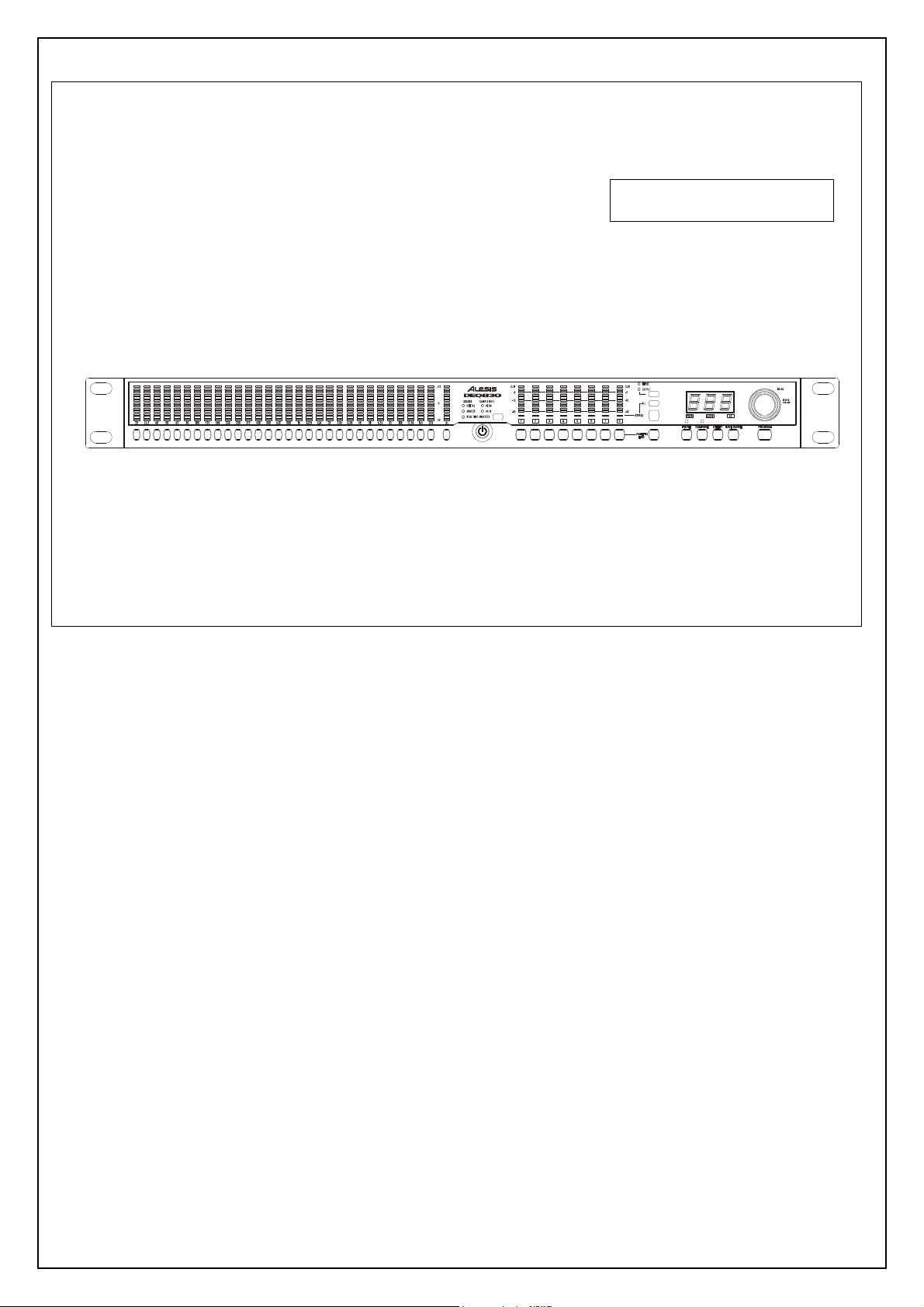
Description of the Front Panel
In this section we give you an overview of the front panel’s
features. Not all features are labeled, so you may want to reference
the diagram of the DEQ830 on page 18 as you read this section.
Band Select
There are 31 buttons side-by-side on the left half of the
DEQ830’s front panel. The first 30 are the [BAND SELECT]
buttons. Above each of the [BAND SELECT] buttons is a
number like "25" or "8k." These stand for the audio frequencies,
measured in Hertz (Hz), which are selected for editing by the
[BAND SELECT] buttons below them. The 31 st button is the
[CHANNEL LEVEL] button, which is explained in the next
paragraph.
Channel Level
The [CHANNEL LEVEL] button is used to set the level of the
currently selected channel or Link Group. This setting is post-EQ
and pre-Master Level.
Real Time Analyzer (RTA)
This button will put the DEQ830 into Real Time Analyzer

mode, in which the unit serves as a visual aid for analyzing the
audio signal. In this mode, the Band Gain LEDs "dance to the
music," displaying the relative strengths of the various frequency
ranges passing through the DEQ830.
Channel Select
To the right of the [POWER] button, you’ll see the
[CHANNEL SELECT] buttons. These eight buttons are used
for selecting a channel for which the EQ settings will be displayed
on the 30 Band Gain LEDs. The [CHANNEL SELECT]
buttons are also used when you are creating Link Groups.
Monitor Select (INPUT/OUTPUT)
This button, located immediately above the [BYPASS] and [ALL]
buttons, toggles between INPUT and OUTPUT to determine
whether the Channel Meters are displaying the input or output
levels. The green LEDs above this button indicate which
monitoring method is currently selected.
Bypass
When you press this button, a red LED will light immediately
above the currently selected channel. This means the DEQ830 is
in Bypass mode for that channel. As long as this LED is lit,
incoming audio will pass through that channel without being
affected by its EQ settings. Also, if you’re on a linked channel
when you press the [BYPASS] button, all of the linked channels
will bypass at the same time. Bypass mode is useful for comparing
the "equalized" signal with the original signal so you can decide if
you like the edit you made. Press the button again to get out of
Bypass mode and hear the effect.
Bypass All (ALL)
This button is located just above the [BYPASS] button. It will
toggle the Bypass status of all eight channels at once. The first
press of the [ALL] button will cause any un-bypassed channels to
enter Bypass mode, after which all eight channels will change their
Bypass status together. When you press this button, the red LED
below each channel meter will light. Press it again to return all
eight channels to their effected state.
Link (PUSH TO LINK)
This button is used to link channels together so that their EQ
settings are “mirrored.” Any edits you make to a band on the
original channel will also happen to that same band on all linked
channels. This is useful for quickly setting up a program without
having to make independent adjustments for each channel.
Store
Once you have made a program edit you would like to keep, press
this button to enter Store mode. From there you can use the
[VALUE] encoder to select one of the 100 memory locations to
become the new home for the edited program.
Compare
This button will help you if you are editing a program and would
like to hear how the program sounded before you edited it.
Pressing this button will temporarily recall the original program,
and pressing it a second time will restore the edited program. The
green LED above this button lights to indicate that the Band Gain
LEDs are now showing the EQ curve as it appeared before your
edits.
Utility
If you press [UTILITY] while you are in Program mode, you will
enter Utility mode, which lets you edit the Master Level, MIDI
Settings, the internal clock rate and other global parameters. If you
press this button at startup as the DEQ830’s splash screen is
displayed, you will enter Lock mode. This mode allows you to lock
the front panel buttons.
Save Curve
Press [SAVE CURVE] to save a channel’s EQ curve to the
DEQ830’s curve bank so that it can be retrieved at a later time.
We’ve provided 100 locations (00-99) in which to save curves.
Curves 00-49 contain factory presets, and curves 50-99 are blank.
Any of the 100 curves may be modified and saved.
Program
If you want to cancel any action in progress and return to
Program mode, just press the [PROGRAM] button.
Value Encoder (VALUE)
To the far right side, you’ll see the [VALUE] encoder, which is
used to edit the gain amount of the frequency you have selected
with the [BAND SELECT] buttons. (It is also possible to select
and edit several frequencies at once; more about this later.) The
[VALUE] encoder is also used for all sorts of data entry, such as
selecting programs and curves, changing global parameter values
and so forth. Changes made with the [VALUE] encoder are
reflected in the Numerical LED Display to the left of the knob.
Numerical LED Display
The three-digit LED display you see to the left of the [VALUE]
encoder is always showing either a value or an abbreviated name.
To help you know at a glance what sort of information the display
is giving you, there are three green LEDs immediately below the
Numerical LED Display:
PROG If this LED is lit, this means the value in the
display is a program number. You will see this
when the unit is in Program mode or Store
mode.
CURVE When lit, this LED indicates that the number
in the display is telling you which curve has
been chosen.
dB This LED tells you that the value in the
display pertains to a gain change.
The only time that none of these LEDs will be lit is when the
DEQ830 is in Utility mode.
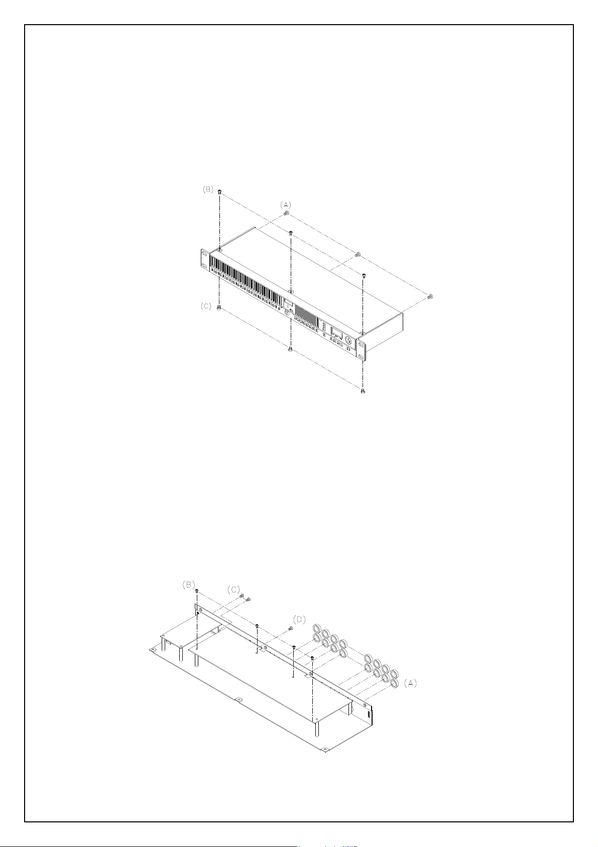
DISASSEMBLY PROCEDURES
BOTTOM CHASSIS.
1. REMOVAL OF TOP COVER / FRONT PANEL (Fig1)
(A) TAKE OUT THE 3PC SCREWS FROM WHICH
THE REAR PANEL.
(B) TAKE OUT THE 3PC SCREWS FROM WHICH
THE TOP PANEL.
(C) TAKE OUT THE 3PC SCREWS FROM WHICH
THE
Fig.1
2. REMOVAL OF MAIN P.C.B (Fig2)
(A) REMOVE THE 16 PCS NUT OF 1/4” CONNECTORS REAR PANEL.
(B) REMOVE THE 4 PCS SCREW FROM WHICH MAIN P.C.B.
(C) REMOVE THE 2 PCS SCREW FRON WHICH REAR PANEL.
(D) REMOVE CABLE CONNECTOR FROM.
(E) REMOVE THE SCREW FROM RCA SOCKET.
Fig.2
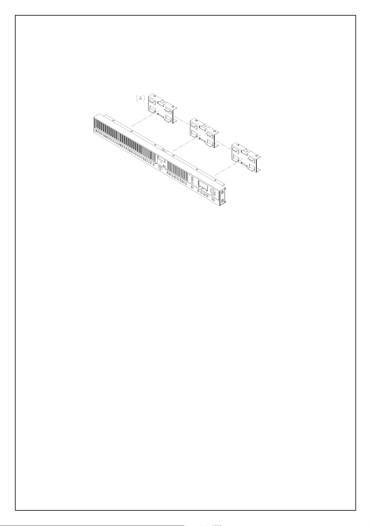
DISASSEMBLY PROCEDURES
3.REMOVAL OF FRONT PAREL P.C.B (Fig.3)
(A.) REMOVE THE 3PC OF SUB-PANEL.
Fig.3
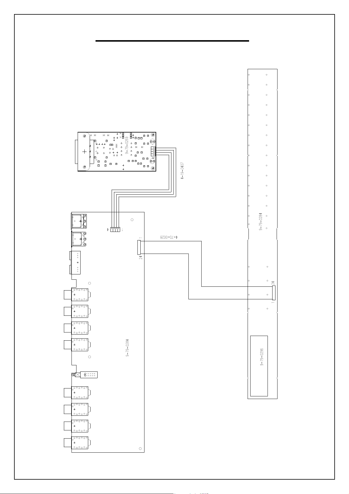
WIRING DIAGRAM
(US/EU/UK/AUS NZ)
P1
J1
P1
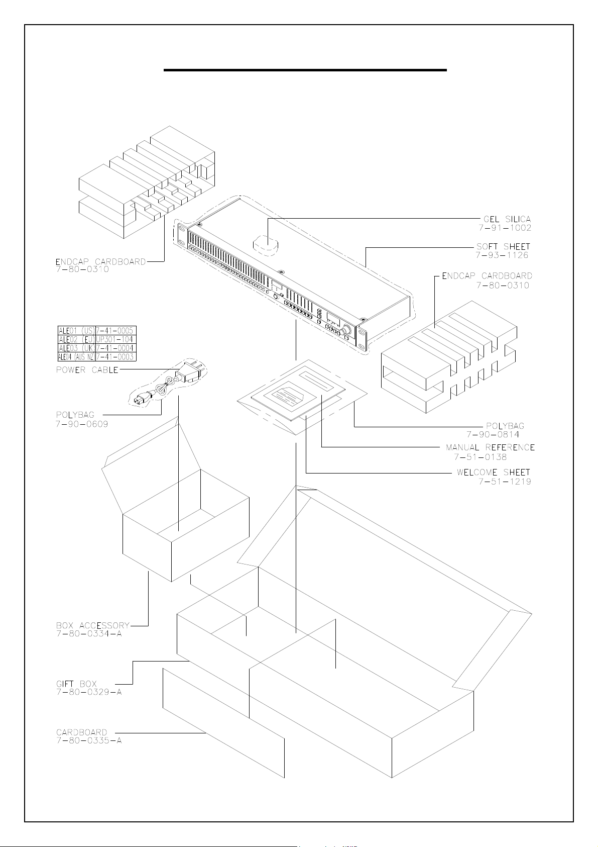
PACKING DIAGRAM
(US/EU/UK/AUS NZ)
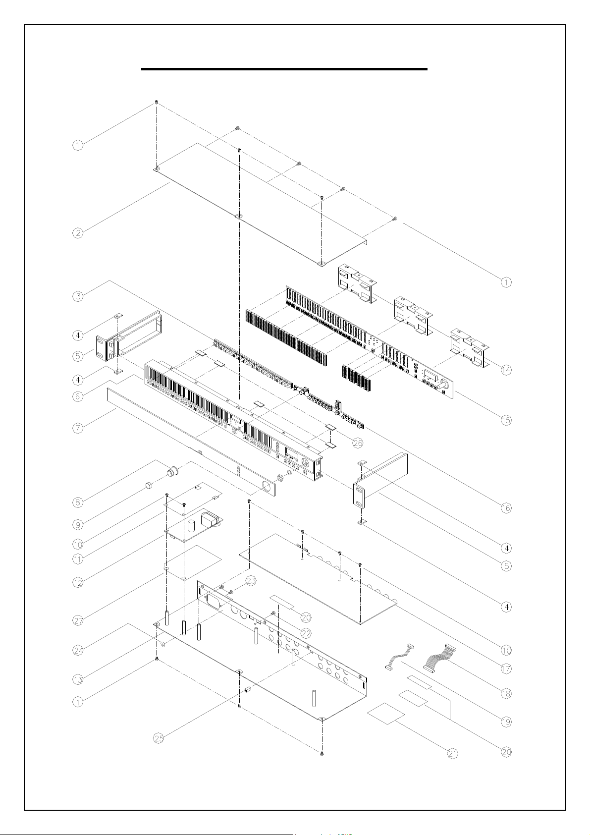
EXPLODE DIAGRAM
(US/EU/UK/AUS NZ)
SEQUENCIAL NO OF EXPLODE DIAGRAM WILL BE MARKED ON REF. COLUMM OF BOM LIST

DEQ830 BOM
LEVEL
1 7-50-0180 STICKER BARCODE S/N 1 20
1 LAP67YAH255 STICKER 1.4
1 LA67YH104 STICKER 1 24
1 9-03-0061 CLIP EMC GND FRONT PANEL 6 26
1 9-02-0012 RACK EAR 1-U 128mm SILVER 2 5
1 9-03-0139 SUBPANEL 3 14
1 9-03-0147-A CHASSIS TOP COVER 1 2
1 9-01-0059-A CHASSIS 1 13
1 9-10-0060-A BEZEL DISPLAY 2.5 THICK CLEAR 1 7
1 PDEQ830ALE01 PACKING ASSEMBLY 1
2 7-80-0310 ENDCAP CARDBOARD/PRESSBOARD 2
2 7-80-0335-A CARDBOARD 1
2 7-80-0334-A ACCESSARY BOX 1
2 7-80-0329-A GIFT BOX 1
2 7-80-0330-A BOX SHIPPING FREIGHT (5 UNITS PER) 0.1
2 7-51-0138-A MANUAL REFERENCE 1
2 7-90-0609 POLYBAG 0.14
2 7-93-1126 BAG FOAM 1
2 7-51-1219 SHEET "WELCOME TO ALESIS FAMILY" 5 x 8" 1
2 7-91-1002 GEL SILICA 5G PACKET 1
1 7-07-0056-A INSULATOR SHEET 1 11
1 9-15-1099 CAP SWITCH 5 x 5mm 1 25
1 9-15-0323-A KNOB VALUE 1 8
1 9-03-0148-A PANEL FRONT 1 6
1 9-24-0002-A GASKET 4 4
1 9-30-0023 KEYPAD RUBBER BAND-SELECT 1 3
1 9-30-0025-A KEYPAD RUBBER CHAN SELECT 1 16
1 9-32-0021-A KNOB SLEEVE RUBBER 1 9
1 SC0306RICI SCREW M3x6mm 6 10
1 SC0308RBNI SCREW M3X8mm PPB PHIL-SLOT 1 22
1 SC0410RACI SCREW M4x10mm 2 23
1 SC3506AICI SCREW M3.5X6mm 10 1
1 4-19-0407 CABLE 4-PIN 1 19
1 4-70-0028 CABLE 24-PIN 1 18
1 7-41-0005 POWER UL/CSA(SJT) 1
1 7-52-0040 STICKER ETL/FCC/CE/C-TICK & CAUTION 1 21
1 7-07-0061-A INSULATOR POWER SUPPLY FORMEX 1 27
1 9-79-0283 ASSY FRONT PANEL ME4
2 0-15-0101 RES 100OHM 1/10W 5% 0805 1 R36
2 0-15-0102 RES 1K OHM 1/10W 5% 0805 1 R37
2 0-15-0820 RES 82 OHM 1/10W 5% 0805 6 R38~43
2 0-17-0101 RES CHIP ARRAY 4 X 100 OHM 1/16W 5% 4 R1,2,19,22
2 0-17-0102 RES CHIP ARRAY 4 X 1K OHM 1/16W 5% 18 R3~6,11,14~18,20,21,27~29,32,34,35
2 0-17-0560 RES CHIP ARRAY 4 X 56 OHM 1/16W 5% 12 R7~10,12,13,23~26,30,31
2 1-56-0103 CAP 0.01UF 10 C1~8,10,13
2 1-56-0104 CAP 0.1UF 1 C18
2 1-56-0474 CAP 0.47UF 5 C11,12,14~16
2 1-60-3222 CAP 22UF ELEC 16V 1 C17
2 2-51-4401 TRANS NPN 2N4401 43 Q17~59
2 2-54-0064 TRANS PNP 2N4403 16 Q1~16
2 2-62-0595 IC 74HC595 8 U2~6,8,9,11
2 2-69-2456 IC EEPROM SERAIL 256K-BIT 1 U10
2 3-02-0048 LED BLUE 6 D512~517
2 3-20-0009 LED GREEN 99
P/N DESCRIPTION QTY REF
15
D7,20,33,46,59,72,85,98,111,124,137,150,163,176,189,202,
215,228,241,254,267,280,293,306,319,332,345,358,371,384
,397,404~407,412~417,420,425~430,433,438~443,446,451~
456,459,464~469,472,477~482,485,490~495,498,503~508,5
11,520~526,528

2 3-20-0010 LED YELLOW 404
C9,14,21,22,78,79,113,114,122,123,131,132,141,142,150,1
D1~6,8~19,21~32,34~45,47~58,60~71,73~84,86~97,99~110
,112~123,125~136,138~149,151~162,164~175,177~188,190
~201,203~214,216~227,229~240,242~253,255~266,268~27
9,281~292,294~305,307~318,320~331,333~344,346~357,35
9~370,372~383,385~396,398~403,409~411,419,422~424,43
2,435~437,445,448~450,458,461~463,471,474~476,484,487
~489,497,500~502,510
2 3-20-0011 LED RED 16
D408,418,421,431,434,444,447,457,460,470,473,483,486,49
6,499,509
2 4-20-1002 10PIN CONNECTOR 2 CN1,CN2
2 4-20-0242 HEADER DIL 24-PIN 1 J1
2 6-02-0055 SWITCH TACT 50 S1~17,26~49,SS17~25
2 7-01-0040 RESONATOR 18MHz 1 M1
2 9-40-0283 FUNCTION PCB 1
2 9-15-0295 FRAME LED 6-COLUMNS x 13 LEDS 5
2 9-15-0373-A FRAME LED 2 COLUMN CHANNEL METER 4
2 9-15-0372-A FRAME LED 1- COLUMN x 13 LEDS 1
2 9-61-0090 IC89C51rd+iB 1 U1
1 9-79-0284 ASSY REAR PANEL ME4
17
2 0-15-0101 RES 100 OHM 1/10W 5% 1 R224
2 0-15-0103 RES 10K OHM 1/10W 5% 7 R41,59,263~266,268
2 0-15-0113 RES 11K OHM 1/10W 5% 16 R3,4,43,44,76,77,84,85,98,99,106,107,124,125,132,133
2 0-15-0133 RES 13K OHM 1/10W 5% 16 R15,16,26,27,144,145,166~169,190,191,200,201,222,223
2 0-15-0163 RES 16K OHM 1/10W 5% 16 R1,2,45,46,74,75,86,87,96,97,108,109,122,123,134,135
2 0-15-0182 RES 1.8K OHM 1/10W 5% 16 R5,10,39,40,80,81,88,89,94,95,102,103,128,129,136,137
2 0-15-0221 RES 220 OHM 1/10W 5% 3 R34,37,38
2 0-15-0331 RES 330 OHM 1/10W 5% 65
2 0-15-0392 RES 3.9K OHM 1/10W 5% 32
2 0-15-0512 RES 5.1K OHM 1/10W 5% 16
R28~33,35,47~52,60,61,63,66,67,90~93,138~143,159,160,1
75,176,192~199,215,216,225~228,245~262,267
R20,56,58,64,68,73,110,115,116,121,151,156,179,184,207,
212,229~244
R11,12,24,25,146,147,164,165,170,171,188,189,202,203,22
0,221
2 0-15-0622 RES 6.2K OHM 1/10W 5% 16 R13,14,17,23,148,161~163,172~174,187,204,217~219
R6~9,18,19,21,22,36,42,53~55,57,62,65,69~72,78,79,82,83,
2 0-15-0912 RES 9.1K OHM 1/10W 5% 64
100,101,104,105,111~114,117~120,126,127,130,131,149,15
0,152~155,157,158,177,178,180~183,185,186,205,206,208~
211,213,214
2 1-08-0222 CAP 22UF ELEC 16V 37
C3,8,32,33,35,40,47,49,50,52~57,61,62,68,69,82,83,89,90,9
7,98,104,105,152,154~161,165
2 1-08-0228 CAP 2200UF ELEC 16V 1 C41
C1,2,4~7,10,20,23~26,58,59,64,65,70,71,76,77,86,87,92~95
2 1-55-0561 CAP 560PF NPO 48
,100,101,106,107,115~117,119~121,124~126,128~130,143,
144,145,147~149
C11~13,15~19,27~31,34,36~39,42~46,48,51,60,63,66,67,72
2 1-56-0103 CAP 0.01UF 63
~75,80,81,84,85,88,91,96,99,102,103,108~112,118,127,133
~140,146,162,163,166,167
2 1-56-0151 CAP 150PF 16
2 2-11-2940 REG VOLTAGE LM2940C 3 U7,9,42
2 2-11-7905 REG VOLTAGE LM7905 1 U5
2 2-24-0138 IC 6N138 1 U12
2 2-27-0051 ASIC OPTO-REC AL1402 1 U39
2 2-27-0056 ASIC OPTOGEN AL1401A 1 U8
2 2-51-4401 TRANS NPN 2N4401 1 Q1
2 2-62-0000 IC 74HC00 2 U10,40
2 2-71-0084 IC TL084 12 U1~3,6,13,18,20,28,31~33,37
2 2-73-4053 IC CD4053 8 U14,15,21,24,27,29,34,35
2 2-75-1101 IC AL1101 4 U16,19,23,25
2 2-75-1201 IC AL1201 4 U4,30,36,38
2-77-0095 IC DSP 1KS/AL3102
2
4-00-0002 JACK DIN 5-PIN MIDI PCB MOUNT
2
4-02-0902 JACK 1/4" STEREO DUAL STACKED
2
4-11-0001 CON FIBER-OPTIC
2
4-14-0242 HEADER DIL 24-PIN
2
4-15-0204 HEADERSIL 4-PIN
2
U11,17,22,26,41
5
J10,11
2
J1~8
8
J9
1
J12
1
J13
1

5-02-0009 HEATSTNK
2
6-02-0014 SWITCH
2
9-40-0284 I/O PCB
2
7-13-0036-A HEATSINK ALUM 23.5mm x 16mm
2
5-04-0061-A INSULATOR 4.1mm x 18mm PLASTIC
2
SC0308RBZI SCREW
2
SC0308RIZI SCREW
2
5-01-0029 WASHER
2
9-79-0296 SENSOR PCB ASSY ME4
1
2 3-04-0014 LED DISP 7-SEG
2 6-00-0009 ENCODER 15-DETENT
2 5-04-0063-A LCD FRAME
(U5,7)
2
S1
1
1
1
1
2
2
2
1
D527
1
S50
1
1 9-79-BB01 ASSY BB01 POWER SUPPLY
JW5206T JUMP WIRE
2
NUT0130IZI NUT
2
SC0308RIZI SCREW
2
5-04-0007 WASHER
2
0-00-0221 RES 220 OHM 1/8W 5%
2
0-00-0689 RES 6.8 OHM 1/8W 5%
2
0-01-2213 RES 221K OHM 1/8W 5%
2
0-05-1104 RES 100K OHM 1W 5%
2
1-02-0104 CAP 0.1UF
2
1-02-5103 CAP 0.01UF
2
1-08-0474 CAP 47UF ELEC 16V
2
1-08-1000 CAP 1000UF ELEC 16V
2
1-09-0221 CAP 220UF ELEC 25V
2
1-13-4472 CAP 47UF ELEC400V
2
1-14-0104 CAP 0.1UF X2-CAP +/20% 250VAC
2
1-15-0103 ELECT 0.01UF/250VAC
2
1-15-2102 CAP 1000PF Y-CAP 250VAC
2
2-01-0120 DIODE MUR120
2
2-01-5822 DIODE 1N5822
2
2-02-0600 DIODE MUR160
2
2-02-4751 DIODE 1N4751
2
2-03-0105 RECTIFIER BRIDGE DB 105 600V 1A
2
2-05-0223 TRANS OFF-LINE PWM SWITCH
2
2-24-8104 IC OPTO-ISOLATOR TCDT1124
2
2-99-0021 DIODE BAV21
2
4-09-0010 CON PWR IEC 10A 250V
2
4-15-0204 HEADER SIL 4-PIN
2
5-05-1001 CLIP FUSE HOLDER 5 X 12mm
2
7-04-0012 FUSE 2A 250V 5X20mm F UL-LISTED
2
2 7-13-0035 HEATSINK 1
7-20-0064 INDUCTOR 100uH
2
7-20-0065 INDUCTOR 22uH
2
7-30-0025 CHOKE COMMON MODE 10mH
2
7-40-0038 TRANSFORMER HI-FREQ SWITCHING FLYBACK
2
2 9-07-0031 SHIELD EMI/IEC BB 1
2 9-40-BB01 PCB POWER SUPPLY 10W - REV B 1
2 7-53-0231-A STICKER FUSE RATING T1AL 250V 1
2 5-04-0062-A INSULATOR 19mm x 20mm PLASTIC 1
2 5-01-0029 WASHER 1
2 5-01-0035 WASHER 1
2 7-07-0023 INSULATOR PPLY PAD 1
12
J3
1
(Q2)
1
(Q2)
1
(Q2)
1
R1
1
R2
1
R3,4
2
R5
1
C1
1
C6
1
C5
1
C7,9
2
C2,4,10,12
4
C11
1
C3,8
2
C14,15
2
C13
1
D2,6
2
D3
1
D4
1
D5
1
D7
1
Q2
1
Q1
1
D1
1
J2
1
J1
1
F1
1
lnstall with F1
1
(Q2)
L1,4
2
L2
1
L3
1
T1
1

ME4 QC Test Procedures
Purpose: Explains test procedures for ME4 (DEQ-230D) for quality assurance
of sub-assembly electronic functionality and audio fidelity, and final
assembly functionality.
NOTE! These procedures DO NOT contain tests for safety/EMC compliance, or
structural, assembly, or packaging quality.
Original Document Type: Word 2000
Current Revision: 1.00 FINAL APPROVED FOR MASS PRODUCTION.
Revision History:
Peter Maresh
Peter Maresh
03/31/2003 1.00 Changed analog tests to work at -10dBV nom.
Changed analog test label in diagnostics menu.
Moved to version 1.00
Peter Maresh
Questions or Comments Contact
Peter Maresh
Design Engineer, Alesis Studio Electronics, Los Angeles
pmaresh@alesis.com
Taiho Yamada
ME4 Project Manager, Alesis Studio Electronics, Los Angeles
tyamada@alesis.com
10/25/2002 0.01 Initial Revision. Copied from ME3 Final QC.
Updated for ME4.
02/24/2003 0.02 Completed Revision

Contents
1) QC Test Overview...................................................... 3
1a) Diagnostic Menus..................................................... 4
DIAG................................................................... 4
EEPROM................................................................. 4
COL.................................................................... 4
ROW.................................................................... 4
ALL.................................................................... 4
MIDI................................................................... 4
A...................................................................... 4
DIG A.................................................................. 4
RESET.................................................................. 4
DONE................................................................... 4
2) Rear Panel Sub Assembly Test - Digital................................ 5
Items Required......................................................... 5
Assembly............................................................... 5
Power Test............................................................. 6
Digital and MIDI Test.................................................. 7
3) Rear Panel Sub Assembly Test - Analog................................ 10
Items Required........................................................ 10
Assembly.............................................................. 10
Power Test............................................................ 11
Audio Fidelity Test................................................... 12
4) Front Panel Sub Assembly Test........................................ 14
Items Required........................................................ 14
Assembly.............................................................. 14
Power Test............................................................ 14
Front Panel Test...................................................... 15
5) Assembly QC.......................................................... 27
Before the cover is screwed on........................................ 27
After the cover has been screwed on................................... 27
6) Final Assembly QC.................................................... 28
Items Required........................................................ 28
Assembly.............................................................. 28
Power Test............................................................ 28
System Test........................................................... 28
7) Reset................................................................ 41
Items Required........................................................ 41
Reset................................................................. 41

1) QC Test Overview
QC tests are performed at two primary stages, sub-assembly level, and final
assembly level. Although several of the procedures are repeated during
both stages, the sub-assembly level tests are designed to test all
functionality of the electronic sub-assemblies, while the final assembly
tests are designed to catch assembly errors. Between the sub-assembly and
final assembly tests, the unit should be inspected for mechanical assembly
quality. After the tests, the unit is Reset before being packaged.
Note that these tests are for the unit assembly. These tests do not
include packaging and shipping QC.
The structure of the tests are as follows:
Electronic Sub-Assemblies QC
Rear Panel – Digital
Test Power for operation
Test MIDI for electrical operation
Test Digital Input for electrical operation
Test Digital Output for electrical operation
Rear Panel - Analog
Test Audio Fidelity for electrical operation
Front Panel
Test Buttons for electrical operation
Test LED display for electrical operation
Test EEPROM for electrical operation
Assembly QC
Specifics of this QC are to be supplied by manufacturer.
Final Assembly QC
Test LED display for appearance
Test Switches for mechanical connectivity
Test Audio for Sub-Assembly connectivity
Test Power for Sub-Assembly connectivity
Reset System
System is Reset for final packaging.
The unit should be inspected before the top panel is closed for
correct assembly. All screws, sub-panel assembly, cabling
should be inspected for completion and correctness.
Inspection for appearance and mechanical completion after the top
panel is closed for correct final assembly. All external
screws, nuts, washers, plastic finish, metal finish, and
silkscreen should be inspected for completion, quality and
correctness. There should be no scratches and the colors and
text should be verified against the latest design for both the
front and back of the unit.
Test Digital In to Analog Out

1a) Diagnostic Menus
When entering diagnostic mode, pressing PROGRAM will advance to the next
test. The test order is as follows:
DIAG -> EEPROM -> COL -> ROW -> ALL -> MIDI -> A. ->
DIAG
Message
Informs user “Prepare for tests.”.
EEPROM
Eeprom Test
When entering EEPROM test, EEPROM test is run automatically. Unit displays
EEPROM FAIL or EEPROM PASS.
COL
LED Test
Turning the VALUE encoder clockwise rotates through LED columns.
ROW
LED Test
Turning the VALUE encoder clockwise rotates through LED rows.
ALL
LED Test
When entering ALL test, unit turns all LEDs on.
MIDI
MIDI Test
When entering MIDI test, MIDI test is run automatically. Unit displays
MIDI FAIL or MIDI PASS. Requires MIDI loopback cable to PASS.
A.
Audio Fidelity Test
When entering AUDIO test, unit configures dsp for bypass to run audio
tests. This uses an abbreviated title, “A,” to reduce noise caused by the
led matrix scanning.
DIG A.
Digital Audio Test
When entering DIG AUDIO test, digital audio test is run automatically.
Unit displays DIG PASS or DIG FAIL. Requires ADAT Optical loopback cable
RESET
EEPROM Reset
Allows user to reset EEPROM. Push encoder to RESET eeprom. Unit displays
0 to 99 in the 7 segment display, and is finished when the display reaches
“99”.
DONE
Message
Informs user “Done with tests.”.
DIG A. ->RESET -> DONE
PASS. to

2) Rear Panel Sub Assembly Test - Digital
Items Required
1 ME4 Rear Panel (DUT)
1 Known Good ME4 Front Panel Sub-Assembly (Front Panel)
1 Known Good BB01 Power Supply with internal 4-pin power cable
1 IEC power cable
Assembly
1) Connect 24 pin DIL cable from the Front Panel J6 to the DUT J12. Be
2) Connect the 4 pin clip-lock power cable from the BB01 Power Supply to
3) Connect the 5-pin DIN Male to Male MIDI Cable from the MIDI IN jack
4) Sub Assembly is ready for testing. Continue with Power Test.
This front panel should have been reset as described in Section 7
“RESET.”
1 ADAT Optical cable
1 24 pin DIL cable for Rear Panel to Front Panel connection.
1 5-pin DIN Male to Male standard MIDI cable
sure that the Pin 1 stripe on the cable is oriented correctly on both
sub-assemblies.
the DUT J13.
to the MIDI OUT jack.

Re ar Panel Sub Assembly Test – DIGITAL CON’T
Power Test
1) Before applying power, visually inspect the DUT for major assembly
2) Plug the IEC Power Cable into a power source and BB01.
3) Unplug the IEC Power Cable to the BB01 Power Supply. Continue with
problems.
Verify that U9 has a metal heat-sink that has been properly
screwed tightly to the metal tab with heat conducting gel.
Verify that U7, U5 has been installed correctly and that the
metal tab has been screwed to the HEAT SINK plane and is making
a good connection to the plane.
Verify all Electrolytic capacitors for correct orientation.
C35, C55, C56, C40, C41, C165
C5, C13, C10, C65, C66, C64, C101, C102, C100, C86, C85, C87
C52, C50, C47, C49, C54, C53, C57, C152, C157, C156, C154,
C155, C159, C160, C161
Problems with this inspection indicate that the DUT has FAILED.
Failure of this inspection indicate that the DUT cannot
continue further testing.
Verify that the front panel LEDs show normal power up message,
“DEQ830” on the left side.
Verify that the LEDs do not flicker and are of a consistent
brightness.
Problems with this inspection indicates that the rear panel is
not supplying the correct voltage to the Front Panel. Double
check that the 24 pin DIL cable has been installed correctly.
If this is not the problem, then the DUT has FAILED.
Failure of this test indicates that this sub-assembly cannot
continue further testing. Quickly check the ICs on the Front
Panel. If any are hot, or if there is any other indication
that the Front Panel may have been damaged (burning smell,
etc.), follow QC procedures to check the Front Panel, because
the faulty DUT power supply may have damaged the Known Good
Front Panel.
Audio Fidelity Test if DUT has not failed.

Rear Panel Sub Assembly Test – DIGITAL CON’T
Digital and MIDI Test
1) Press the UTILITY and CHANNEL 7 buttons on the Known Good ME4 Front
2) Plug the IEC Power Cable into a power source and BB01.
3) When in Factory Test Mode, pressing PROGRAM will go to next test.
4) Press PROGRAM until unit displays “MIDI.”
Panel Sub-Assembly and hold these buttons during Step 2. When started
in this manner, the unit will enter Factory Test Mode. Please Note
Section 1b on the Diagnostic Mode.
Verify that the front panel LEDs show normal power up message,
“DEQ830” on the left side..
After this message “DIAG: <version>” should display on the left
side. Verify that the version is the correct, shipping version
number for the ME4.
Problems with this inspection indicates that the unit has not
entered Factory Test Mode. Unplug the unit and repeat steps 1
and 2.
Problems with the correct version number indicate that the
Known Good ME4 Front Panel has the incorrect software in it,
and that it should be updated to the most recent software.
Failure of this test indicates that this sub-assembly cannot
continue further testing.
Press PROGRAM.
Verify that the front panel LEDs shows first test message
“EEPROM” for 1 second.
Verify that the front panel LEDs shows first test message
“EEPROM PASS”.
Problems with this inspection indicates that the unit is having
trouble recognizing the PROGRAM button, or that the EEPROM has
failed.
Failure of this test indicates that there is something wrong
with the ME4 Known Good Front Panel.
Verify that the front panel LEDs shows test messages:
EEPROM -> COL -> ROW -> ALL -> SWITCH
STOP here.

Rear Panel Sub Assembly Test – DIGITAL CON’T
5) Press PROGRAM. This runs the MIDI test.
6) Press PROGRAM once to advance to the audio (“A.”) test.
7) Connect one end of the ADAT Optical cable from DUT Optical OUT to DUT
Optical IN.
8) Press PROGRAM once to continue to the DIG AUDIO test. The analog
audio test will be performed later.
Verify that the front panel LEDs shows test “MIDI” for 1
second.
Verify that display shows “MIDI PASS”.
Problems with this inspection indicate that there is a MIDI
electrical or cabling problem. Try adjusting or replacing the
MIDI Cable, unplug the IEC Cable and repeat steps 1 through 5.
If the error message still shows after adjusting the cable,
then the DUT has FAILED.
Failure of this test indicates that this sub-assembly cannot
continue further testing.
Verify that the source indicator in the middle of the front
panel shows the audio switching from “ANALOG” to “DIGITAL”, and
that the “DIGITAL” indicator stays lit solid.
Problems with this inspection indicate that there is a optical
audio problem. Try adjusting or replacing the ADAT Optical
Cable, unplug the IEC Cable and repeat steps 1 through 6.
Also, verify that the Known Good Front Panel has been properly
RESET as described in Section 7 “RESET”. If after reseting the
Front Panel and adjusting the loopback cable, the unit does not
switch to “DIGITAL” then there is a problem with ADAT Optical
and the DUT has FAILED.
Failure of this test indicates that this sub-assembly cannot
continue further testing.
Verify that the front panel LEDs shows test messages:
MIDI -> A. -> DIG A.
Stop here.
Verify that the front panel LEDs shows test “DIG A.” for 1
second.
Verify that display shows “DIG PASS”.
Problems with this inspection indicate that there is a ADAT
Optical electrical or cabling problem. Try adjusting or
replacing the ADAT Optical Cable, unplug the IEC Cable and
repeat steps 1 through 6. If the error message still shows
after adjusting the cable, then the DUT has FAILED.

9) Unplug the IEC Power Cable to the BB01 Power Supply. Then unplug all
other cabling to the DUT. This is the end of the Rear Panel SubAssembly Analog test. Proceed to the Rear Panel Sub-Assembly Digital
test.
Failure of this test indicates that this sub-assembly cannot
continue further testing.
 Loading...