How it Works
Log In / Sign Up
Buy Points
How it Works
FAQ
Contact Us
Questions and Suggestions
Users
Alcatel
Loading...
P
PREMIUM REFLEXES OFFICE
PREMIUM REFLEXES OMNIPCX 4400
PREMIUM RELFEXES
PRENIUM R30
PRENIUM R31
PROFESSIONNEL 2521
Pulsemix
3
PWTB
PWTH
Q
Quality Monitor version 2.4
QuickFlip
4
R
Revvl
ROC3205
S
S210
S211C
S215A
SCRIBE EASY
Scribe HD
SD
Shine Lite
SIGMA 110
Sigma 260
2
SIGMA 260 VOICE
Sillage 1000
Sillage 2000
Slim 300 Voice
Slim 300 Voice Duo
SM-02
6
SM03
Smart 903
Smart 916
Smart 985
Smartband 2
Smart Tab
SMILE
SNAP
SONET-SDH MDAs
Sonic LTE
Sparq
2
SPEDDTOUCH 510 1
SPEDDTOUCH 570
SPEDDTOUCH 591S
SPEDDTOUCH 600
SPEDDTOUCH DSL ROUTERS
2
SPEDDTOUCH HOME
SPEDDTOUCH PRO
2
SPEDDTOUCH PRO WITH FIREWALL
2
SPEEDTOUCH 110G
2
SPEEDTOUCH 120G
2
SPEEDTOUCH 121G
2
SPEEDTOUCH 180
2
SPEEDTOUCH 190
2
Speedtouch 2030
SPEEDTOUCH 350
3
SPEED TOUCH 350I
SPEEDTOUCH 500
SPEEDTOUCH 510
7
SPEEDTOUCH 510I
2
SPEEDTOUCH 510V4
2
SPEEDTOUCH 510 V5
4
SPEEDTOUCH 516
4
SPEED TOUCH 530
3
SPEEDTOUCH 536
3
SPEEDTOUCH 545
SPEEDTOUCH 546
4
SPEEDTOUCH 570
2
SPEEDTOUCH 576
4
SPEEDTOUCH 580
5
SPEEDTOUCH 585
4
SPEEDTOUCH 5X6
SPEEDTOUCH 605
2
SPEEDTOUCH 605S
3
SPEEDTOUCH 608
2
SPEEDTOUCH 608 1
SPEEDTOUCH 608WL
2
SPEEDTOUCH 610
SPEEDTOUCH 610 1
2
SPEEDTOUCH 620
SPEEDTOUCH 620 1
SPEEDTOUCH 710
SPEEDTOUCH 716
SPEEDTOUCH 716 V5
2
Speedtouch 780WL
SPEEDTOUCH BUS
SPEEDTOUCH HOME
Speed Touch Home Asymmetric
SPEEDTOUCH OFFICE
SPEED TOUCH PRO
3
SPEED TOUCH USB
SPEEDTOUCH USB 330
SPEEDTOUCH USB-MANTA
STAR
2
Streak
SX5e
T
T06
T10
T16
T20
2
T22
T26
Loading...
Loading...
Nothing found
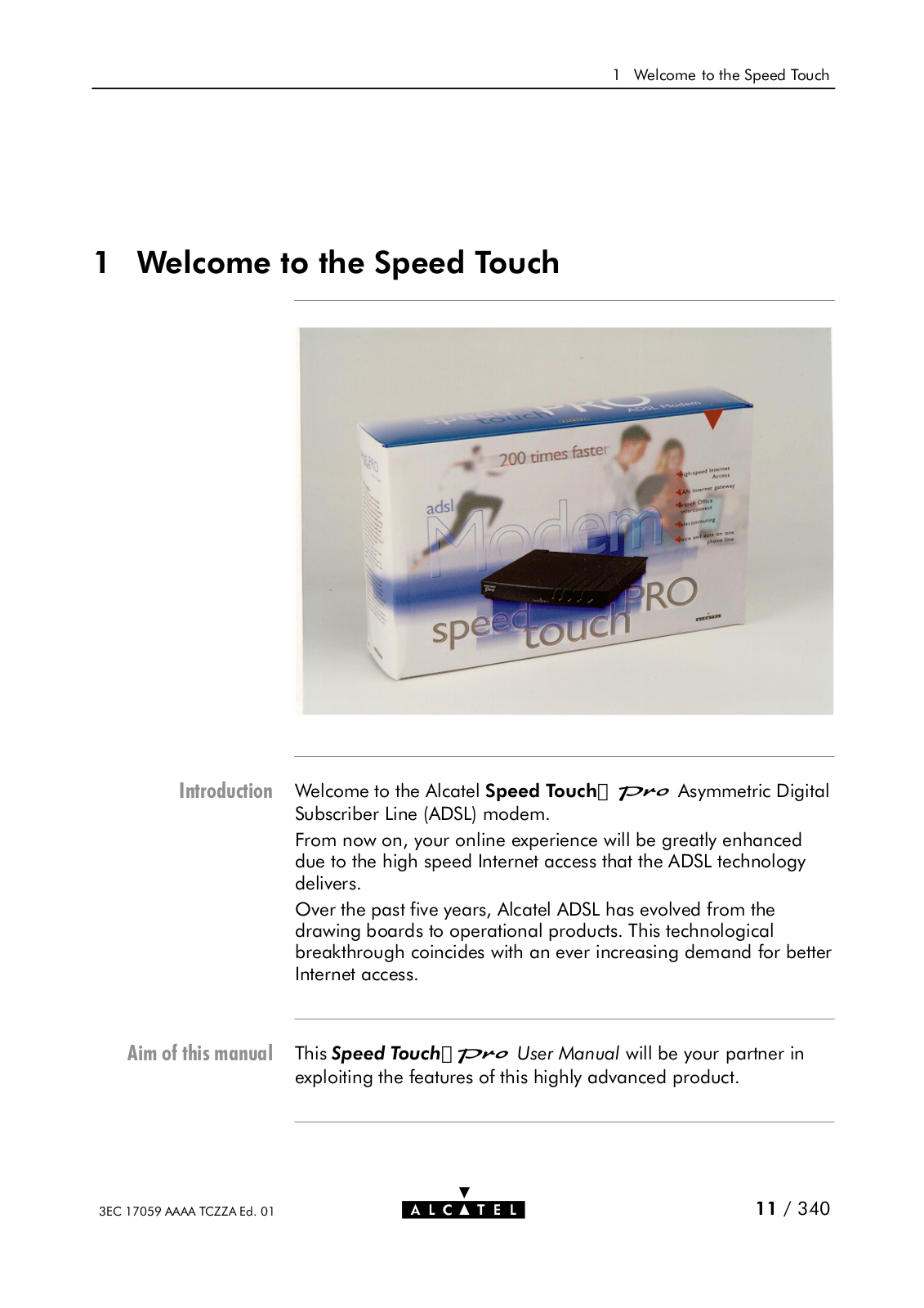
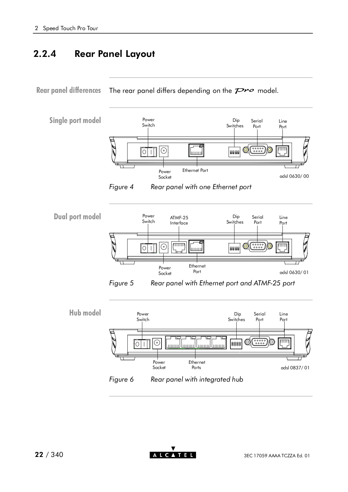
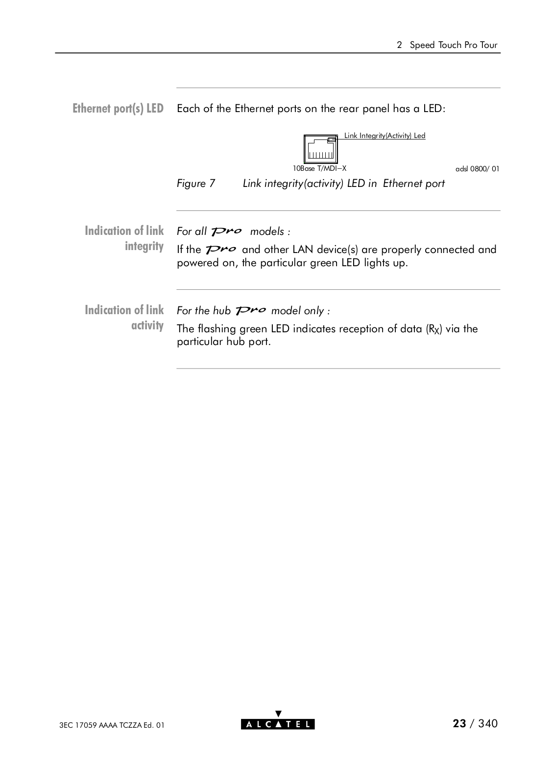
SPEED TOUCH PRO
User Manual
238 pgs
2.88 Mb
0
User Manual
340 pgs
9.92 Mb
0
User Manual [es]
10 pgs
259.5 Kb
0
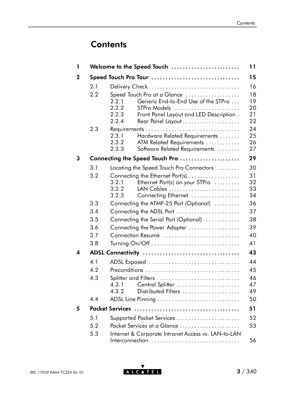
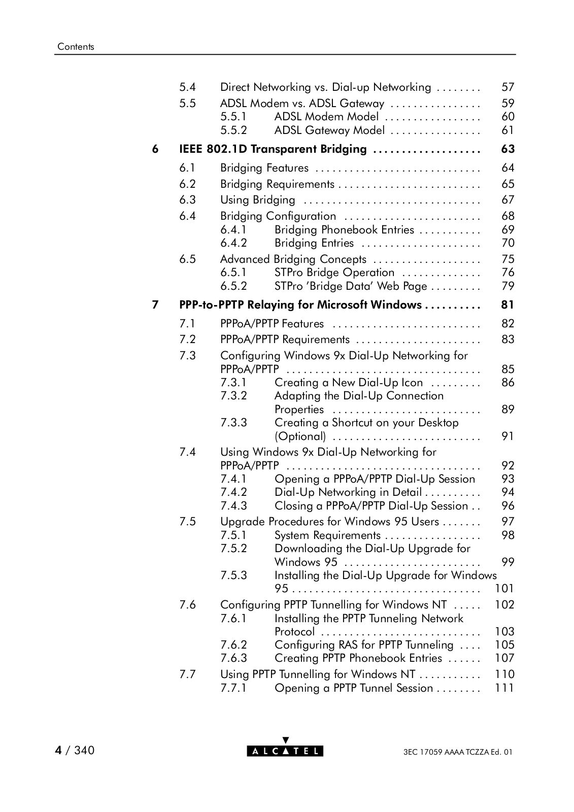
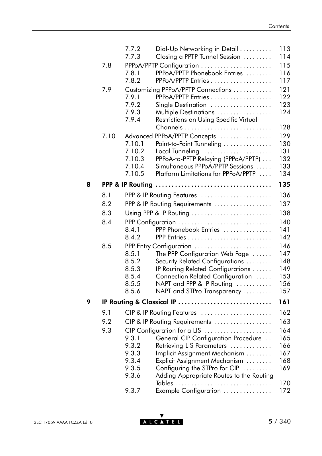
Table of contents
Loading...
Alcatel SPEED TOUCH PRO User Manual
...
Alcatel User Manual
Download
Specifications and Main Features
Frequently Asked Questions
User Manual
Download
Loading...
+
310
hidden pages
Unhide
You need points to download manuals.
1 point = 1 manual.
You can buy points or you can get point for every manual you upload.
Buy points
Upload your manuals
 Loading...