

Page 1

SPEED TOUCH
PRO
WITH FIREWALL
User's Guide
3EC 36231 ABAA TCZZA Ed. 01
Page 2

Status
Released
2 / 288
Change Note
Short Title
BD F aa 36170
CD-UG STPro 3.4.2
All rights reserved. Passing on and copying of this
document, use and communication of its contents
not permitted without written authorization from Alcatel.
3EC 36231 ABAA TCZZA Ed. 01
Page 3

Contents
1 Speed Touch Quick Guide 11. . . . . . . . . . . . . . . . . . . . . . . . . . . . . . . . . . . . . . . . . . . .
1.1 Get Acquainted with your Speed Touch 12. . . . . . . . . . . . . . . . . . . . . . . . . . . .
1.2 Speed Touch Installation 15. . . . . . . . . . . . . . . . . . . . . . . . . . . . . . . . . . . . . . . .
1.2.1 What you Need 16. . . . . . . . . . . . . . . . . . . . . . . . . . . . . . . . . . . . . .
1.2.2 STPro Wiring 17. . . . . . . . . . . . . . . . . . . . . . . . . . . . . . . . . . . . . . . . .
1.2.3 Check your Service Provider's Offering 19. . . . . . . . . . . . . . . . . .
1.2.4 Select an STPro Packet Service 20. . . . . . . . . . . . . . . . . . . . . . . . . .
1.2.5 Configure your STPro (If Necessary) 21. . . . . . . . . . . . . . . . . . . . .
1.2.6 Surf the Internet 22. . . . . . . . . . . . . . . . . . . . . . . . . . . . . . . . . . . . . .
1.2.7 Detailed STPro Information 23. . . . . . . . . . . . . . . . . . . . . . . . . . . .
2 Wiring Guide - Ethernet and ATMF25.6 27. . . . . . . . . . . . . . . . . . . . . . . . . . . . .
2.1 LAN Cables 28. . . . . . . . . . . . . . . . . . . . . . . . . . . . . . . . . . . . . . . . . . . . . . . . . . .
2.2 Connecting Ethernet 29. . . . . . . . . . . . . . . . . . . . . . . . . . . . . . . . . . . . . . . . . . . .
2.2.1 Ethernet Port on the single Ethernet port Model 30. . . . . . . . . . .
2.2.2 Ethernet Ports on the Ethernet Hub Model 31. . . . . . . . . . . . . . . .
2.2.3 Single PC Ethernet Wiring 32. . . . . . . . . . . . . . . . . . . . . . . . . . . . .
2.2.4 LAN Ethernet Wiring 33. . . . . . . . . . . . . . . . . . . . . . . . . . . . . . . . . .
2.3 Connecting the ATMF25.6 Port (Optional) 34. . . . . . . . . . . . . . . . . . . . . . . .
2.4 Ethernet vs. ATMF25.6 Connectivity 35. . . . . . . . . . . . . . . . . . . . . . . . . . . . . .
Contents
3 Wiring Guide - DSL, Power and Console 37. . . . . . . . . . . . . . . . . . . . . . . . . . . . .
3.1 Locating Ports 38. . . . . . . . . . . . . . . . . . . . . . . . . . . . . . . . . . . . . . . . . . . . . . . . .
3.2 Connecting the DSL Port 39. . . . . . . . . . . . . . . . . . . . . . . . . . . . . . . . . . . . . . . .
3.3 Connecting the Power Adapter 40. . . . . . . . . . . . . . . . . . . . . . . . . . . . . . . . . . .
3.4 Connecting the Serial Port (Optional) 41. . . . . . . . . . . . . . . . . . . . . . . . . . . . .
4 Wiring Guide - Resumé 43. . . . . . . . . . . . . . . . . . . . . . . . . . . . . . . . . . . . . . . . . . . . .
5 Configuration and Use - Packet Services 47. . . . . . . . . . . . . . . . . . . . . . . . . . . . .
5.1 Supported Packet Services 48. . . . . . . . . . . . . . . . . . . . . . . . . . . . . . . . . . . . . . .
5.2 Packet Services at a Glance 49. . . . . . . . . . . . . . . . . . . . . . . . . . . . . . . . . . . . .
5.3 Selection Criteria 52. . . . . . . . . . . . . . . . . . . . . . . . . . . . . . . . . . . . . . . . . . . . . .
6 Configuration and Use - Transparent Bridging 53. . . . . . . . . . . . . . . . . . . . . . .
6.1 Preparatory Steps 54. . . . . . . . . . . . . . . . . . . . . . . . . . . . . . . . . . . . . . . . . . . . . .
6.2 Using Bridging 55. . . . . . . . . . . . . . . . . . . . . . . . . . . . . . . . . . . . . . . . . . . . . . . .
6.3 Bridging Configuration 56. . . . . . . . . . . . . . . . . . . . . . . . . . . . . . . . . . . . . . . . .
6.4 Bridge Data 59. . . . . . . . . . . . . . . . . . . . . . . . . . . . . . . . . . . . . . . . . . . . . . . . . . .
3EC 36231 ABAA TCZZA Ed. 01
3 / 288
Page 4

Contents
7 Configuration and Use - Routed Ethernet 61. . . . . . . . . . . . . . . . . . . . . . . . . . . .
7.1 Preparatory Steps 62. . . . . . . . . . . . . . . . . . . . . . . . . . . . . . . . . . . . . . . . . . . . . .
7.2 Using Routed Ethernet 63. . . . . . . . . . . . . . . . . . . . . . . . . . . . . . . . . . . . . . . . . .
7.3 Routed Ethernet Configuration 64. . . . . . . . . . . . . . . . . . . . . . . . . . . . . . . . . . .
8 Configuration and Use - Bridged PPPoE 67. . . . . . . . . . . . . . . . . . . . . . . . . . . . . .
8.1 Preparatory Steps 68. . . . . . . . . . . . . . . . . . . . . . . . . . . . . . . . . . . . . . . . . . . . . .
8.2 Using Bridged PPPoE 69. . . . . . . . . . . . . . . . . . . . . . . . . . . . . . . . . . . . . . . . . . .
8.3 Bridged PPPoE Configuration 70. . . . . . . . . . . . . . . . . . . . . . . . . . . . . . . . . . . .
9 Configuration and Use - Routed PPPoE 71. . . . . . . . . . . . . . . . . . . . . . . . . . . . . . .
9.1 Preparatory Steps 72. . . . . . . . . . . . . . . . . . . . . . . . . . . . . . . . . . . . . . . . . . . . . .
9.2 Using Routed PPPoE 73. . . . . . . . . . . . . . . . . . . . . . . . . . . . . . . . . . . . . . . . . . . .
9.3 Routed PPPoE Configuration 75. . . . . . . . . . . . . . . . . . . . . . . . . . . . . . . . . . . . .
9.4 Detailed Configuration 77. . . . . . . . . . . . . . . . . . . . . . . . . . . . . . . . . . . . . . . . .
9.4.1 'PPPoE' Configurations 78. . . . . . . . . . . . . . . . . . . . . . . . . . . . . . . .
9.4.2 'Routing' Configurations 79. . . . . . . . . . . . . . . . . . . . . . . . . . . . . . .
9.4.3 'Other' Configurations 80. . . . . . . . . . . . . . . . . . . . . . . . . . . . . . . .
9.4.4 'Stats' During a Routed PPPoE Session 81. . . . . . . . . . . . . . . . . . .
10 Configuration and Use - Relayed PPPoA 83. . . . . . . . . . . . . . . . . . . . . . . . . . . . . .
10.1 Preparatory Steps 84. . . . . . . . . . . . . . . . . . . . . . . . . . . . . . . . . . . . . . . . . . . . . .
10.2 Using Relayed PPPoA 85. . . . . . . . . . . . . . . . . . . . . . . . . . . . . . . . . . . . . . . . . . .
10.2.1 Preparing the PC for PPTP Tunneling 86. . . . . . . . . . . . . . . . . . . .
10.2.2 Using PPTP towards your STPro 87. . . . . . . . . . . . . . . . . . . . . . . . .
10.3 Example : MS Windows 98 DialUp Networking 88. . . . . . . . . . . . . . . . . . . .
10.3.1 Create a New DialUp Networking Icon 89. . . . . . . . . . . . . . . . .
10.3.2 Open a DialUp Session 92. . . . . . . . . . . . . . . . . . . . . . . . . . . . . . .
10.3.3 Close a DialUp Session in Use 94. . . . . . . . . . . . . . . . . . . . . . . . .
10.4 Relayed PPPoA Configuration 95. . . . . . . . . . . . . . . . . . . . . . . . . . . . . . . . . . . .
11 Configuration and Use - Routed PPPoA 99. . . . . . . . . . . . . . . . . . . . . . . . . . . . . .
11.1 Preparatory Steps 100. . . . . . . . . . . . . . . . . . . . . . . . . . . . . . . . . . . . . . . . . . . . . .
11.2 Using Routed PPPoA 101. . . . . . . . . . . . . . . . . . . . . . . . . . . . . . . . . . . . . . . . . . . .
11.3 Routed PPPoA Configuration 104. . . . . . . . . . . . . . . . . . . . . . . . . . . . . . . . . . . . .
11.4 Detailed Configuration 108. . . . . . . . . . . . . . . . . . . . . . . . . . . . . . . . . . . . . . . . .
11.4.1 'Routing' Configurations 109. . . . . . . . . . . . . . . . . . . . . . . . . . . . . . .
11.4.2 'Other' Configurations 113. . . . . . . . . . . . . . . . . . . . . . . . . . . . . . . .
11.4.3 'Stats' During a Routed PPPoA Session 117. . . . . . . . . . . . . . . . . . .
12 Configuration and Use - CIP & IP Routing 119. . . . . . . . . . . . . . . . . . . . . . . . . . . .
12.1 Preparatory Steps 120. . . . . . . . . . . . . . . . . . . . . . . . . . . . . . . . . . . . . . . . . . . . . .
12.2 CIP Configuration for a LIS 121. . . . . . . . . . . . . . . . . . . . . . . . . . . . . . . . . . . . . .
12.2.1 General CIP Configuration Procedure 122. . . . . . . . . . . . . . . . . . .
4 / 288
3EC 36231 ABAA TCZZA Ed. 01
Page 5

12.2.2 Retrieving LIS Parameters 123. . . . . . . . . . . . . . . . . . . . . . . . . . . . . .
12.2.3 Implicit Assignment Mechanism 124. . . . . . . . . . . . . . . . . . . . . . . .
12.2.4 Explicit Assignment Mechanism 125. . . . . . . . . . . . . . . . . . . . . . . . .
12.2.5 Configuring the STPro for CIP 126. . . . . . . . . . . . . . . . . . . . . . . . . .
12.2.6 Adding Appropriate Routes to the Routing Tables 127. . . . . . . . . .
12.2.7 Example Configuration 129. . . . . . . . . . . . . . . . . . . . . . . . . . . . . . . .
12.3 Using CIP & IP Routing 131. . . . . . . . . . . . . . . . . . . . . . . . . . . . . . . . . . . . . . . . .
12.4 CIP Configuration 132. . . . . . . . . . . . . . . . . . . . . . . . . . . . . . . . . . . . . . . . . . . . . .
13 Networking - ATM 139. . . . . . . . . . . . . . . . . . . . . . . . . . . . . . . . . . . . . . . . . . . . . . . . . .
13.1 The ATM Packet Switching Technology 140. . . . . . . . . . . . . . . . . . . . . . . . . . . .
13.1.1 ATM Parameters 141. . . . . . . . . . . . . . . . . . . . . . . . . . . . . . . . . . . . . .
13.1.2 ATM and the STPro 142. . . . . . . . . . . . . . . . . . . . . . . . . . . . . . . . . . .
13.1.3 ATM and Interfaces 143. . . . . . . . . . . . . . . . . . . . . . . . . . . . . . . . . . .
13.2 ATMF25.6 Port Configuration 145. . . . . . . . . . . . . . . . . . . . . . . . . . . . . . . . . . .
13.3 The Speed Touch Phonebook 146. . . . . . . . . . . . . . . . . . . . . . . . . . . . . . . . . . . .
13.3.1 The STPro 'Phonebook' Page 147. . . . . . . . . . . . . . . . . . . . . . . . . . .
13.3.2 Using the Phonebook 151. . . . . . . . . . . . . . . . . . . . . . . . . . . . . . . . .
13.3.3 AutoPVC and the Phonebook 153. . . . . . . . . . . . . . . . . . . . . . . . . .
Contents
14 Networking Services - IP 155. . . . . . . . . . . . . . . . . . . . . . . . . . . . . . . . . . . . . . . . . . . .
14.1 Speed Touch and IP 156. . . . . . . . . . . . . . . . . . . . . . . . . . . . . . . . . . . . . . . . . . . .
14.2 Packet Services and IP 158. . . . . . . . . . . . . . . . . . . . . . . . . . . . . . . . . . . . . . . . . .
14.2.1 Transparent Bridging 159. . . . . . . . . . . . . . . . . . . . . . . . . . . . . . . . . .
14.2.2 Relayed PPPoA 160. . . . . . . . . . . . . . . . . . . . . . . . . . . . . . . . . . . . . . .
14.2.3 Routed Packet Services 161. . . . . . . . . . . . . . . . . . . . . . . . . . . . . . . .
14.3 Speed Touch Addresses 163. . . . . . . . . . . . . . . . . . . . . . . . . . . . . . . . . . . . . . . . .
14.3.1 STPro IP Address Types 164. . . . . . . . . . . . . . . . . . . . . . . . . . . . . . . .
14.3.2 Static IP Address Configuration 166. . . . . . . . . . . . . . . . . . . . . . . . .
14.4 Speed Touch DHCP 169. . . . . . . . . . . . . . . . . . . . . . . . . . . . . . . . . . . . . . . . . . . .
14.4.1 STPro DHCP Pages 170. . . . . . . . . . . . . . . . . . . . . . . . . . . . . . . . . . .
14.4.2 The STPro DHCP Server 171. . . . . . . . . . . . . . . . . . . . . . . . . . . . . . .
14.4.3 The STPro DHCP Client 176. . . . . . . . . . . . . . . . . . . . . . . . . . . . . . . .
14.5 Speed Touch Routing 179. . . . . . . . . . . . . . . . . . . . . . . . . . . . . . . . . . . . . . . . . . .
14.5.1 The STPro IP Router 180. . . . . . . . . . . . . . . . . . . . . . . . . . . . . . . . . . .
14.5.2 Configuring the STPro IP Routing Table 183. . . . . . . . . . . . . . . . . .
15 Networking Services - DNS 187. . . . . . . . . . . . . . . . . . . . . . . . . . . . . . . . . . . . . . . . . .
15.1 Speed Touch DNS Resolving 188. . . . . . . . . . . . . . . . . . . . . . . . . . . . . . . . . . . . .
15.2 Configuring the Speed Touch DNS Server 190. . . . . . . . . . . . . . . . . . . . . . . . .
16 Network Security - NAT & PAT 195. . . . . . . . . . . . . . . . . . . . . . . . . . . . . . . . . . . . . . .
16.1 Speed Touch and NA(P)T 196. . . . . . . . . . . . . . . . . . . . . . . . . . . . . . . . . . . . . . . .
16.2 Packet Services and NA(P)T 197. . . . . . . . . . . . . . . . . . . . . . . . . . . . . . . . . . . . . .
16.3 The Speed Touch 'NAT' Page 201. . . . . . . . . . . . . . . . . . . . . . . . . . . . . . . . . . . .
3EC 36231 ABAA TCZZA Ed. 01
5 / 288
Page 6

Contents
16.4 NA(P)T Configuration Example 205. . . . . . . . . . . . . . . . . . . . . . . . . . . . . . . . . . .
17 Network Security - Firewalling 207. . . . . . . . . . . . . . . . . . . . . . . . . . . . . . . . . . . . . .
17.1 Operation of the Firewall 208. . . . . . . . . . . . . . . . . . . . . . . . . . . . . . . . . . . . . . .
17.2 Firewall Model 209. . . . . . . . . . . . . . . . . . . . . . . . . . . . . . . . . . . . . . . . . . . . . . . .
17.3 Firewall Actions 211. . . . . . . . . . . . . . . . . . . . . . . . . . . . . . . . . . . . . . . . . . . . . . . .
17.4 Firewall Criteria 212. . . . . . . . . . . . . . . . . . . . . . . . . . . . . . . . . . . . . . . . . . . . . . .
17.5 Firewalling and NAPT 214. . . . . . . . . . . . . . . . . . . . . . . . . . . . . . . . . . . . . . . . . .
17.6 Firewall Configuration 215. . . . . . . . . . . . . . . . . . . . . . . . . . . . . . . . . . . . . . . . . .
17.7 Firewall Configuration Examples 216. . . . . . . . . . . . . . . . . . . . . . . . . . . . . . . . .
18 Maintenance - Speed Touch Software 221. . . . . . . . . . . . . . . . . . . . . . . . . . . . . . . .
18.1 Software Upload from the local LAN 222. . . . . . . . . . . . . . . . . . . . . . . . . . . . . .
18.2 Software Download from the DSL WAN 227. . . . . . . . . . . . . . . . . . . . . . . . . . .
19 Maintenance - Speed Touch Password 229. . . . . . . . . . . . . . . . . . . . . . . . . . . . . . .
20 Maintenance - Speed Touch ToDefaults 231. . . . . . . . . . . . . . . . . . . . . . . . . . . . . .
20.1 PingofLife 232. . . . . . . . . . . . . . . . . . . . . . . . . . . . . . . . . . . . . . . . . . . . . . . . . . .
20.2 Speed Touch Reset 235. . . . . . . . . . . . . . . . . . . . . . . . . . . . . . . . . . . . . . . . . . . . .
20.2.1 BrowsetoDefaults 236. . . . . . . . . . . . . . . . . . . . . . . . . . . . . . . . . . .
20.2.2 PingtoDefaults 237. . . . . . . . . . . . . . . . . . . . . . . . . . . . . . . . . . . . . .
20.2.3 SwitchtoDefaults 238. . . . . . . . . . . . . . . . . . . . . . . . . . . . . . . . . . . .
21 Maintenance - Speed Touch Web Interface 239. . . . . . . . . . . . . . . . . . . . . . . . . . .
21.1 Web Interface Preconditions 240. . . . . . . . . . . . . . . . . . . . . . . . . . . . . . . . . . . . .
21.1.1 Disabling Proxy Servers 241. . . . . . . . . . . . . . . . . . . . . . . . . . . . . . . .
21.1.2 Disabling Proxying for Local IP Addresses 242. . . . . . . . . . . . . . . .
21.2 Browsing to the Speed Touch Pages 243. . . . . . . . . . . . . . . . . . . . . . . . . . . . . . .
21.3 Speed Touch Page Structure 244. . . . . . . . . . . . . . . . . . . . . . . . . . . . . . . . . . . . .
22 Maintenance - Speed Touch CLI 247. . . . . . . . . . . . . . . . . . . . . . . . . . . . . . . . . . . . .
22.1 CLI via the Speed Touch Pages 248. . . . . . . . . . . . . . . . . . . . . . . . . . . . . . . . . . .
22.2 Native CLI Access 251. . . . . . . . . . . . . . . . . . . . . . . . . . . . . . . . . . . . . . . . . . . . . .
22.2.1 CLI through a Telnet Session 252. . . . . . . . . . . . . . . . . . . . . . . . . . .
22.2.2 CLI via Serial Access 254. . . . . . . . . . . . . . . . . . . . . . . . . . . . . . . . . .
22.2.3 CLI Command Basics 255. . . . . . . . . . . . . . . . . . . . . . . . . . . . . . . . .
Abbreviations 259. . . . . . . . . . . . . . . . . . . . . . . . . . . . . . . . . . . . . . . . . . . . . . . . . . . . . . . . . . . .
AppendixA Speed Touch Troubleshooting 263. . . . . . . . . . . . . . . . . . . . . . . . . . . .
AppendixB Speed Touch Specifications 265. . . . . . . . . . . . . . . . . . . . . . . . . . . . . . .
AppendixC Speed Touch Default Assignments 277. . . . . . . . . . . . . . . . . . . . . . . .
AppendixD Safety and Agency Regulatory Notices 281. . . . . . . . . . . . . . . . . . . .
6 / 288
3EC 36231 ABAA TCZZA Ed. 01
Page 7
Alcatel Speed Touch Pro with Firewall
Introduction
The Alcatel Speed TouchPro with Firewall DSL router provides highspeed access to
the Internet and Corporate networks for small office and fastidious home users and
highspeed inter office LANtoLAN connections.
For optimal Local Area Network (LAN) performance the Alcatel Speed TouchPro with
Firewall includes a comprehensive set of features, as there are a DHCP server, DNS server,
NAT&PAT, CIDR and VLSM to name a few. On top, a programmable firewall allows you to
shield your local network from the Wide Area Network (WAN) and to protect your resources
from intruders.
3EC 36231 ABAA TCZZA Ed. 01
7 / 288
Page 8

Three STPro router
y
variants
Three variants of Alcatel's Speed TouchPro with Firewall DSL
routers exist:
Two Asymmetric Digital Subscriber Line (ADSL) variants:
A ADSL/POTS variant connecting to an analog POTS(*)
line
A ADSL/ISDN variant connecting to a digital ISDN(**) line
One Singlepair High Speed Digital Subscriber Line (SHDSL)
variant:
The SHDSL variant connecting to a dedicated SHDSL
twowire line.
(*) Plain Old Telephone Service (POTS)
(**) Integrated Services Digital Network (ISDN)
Terminolog
Safety instructions
CAUTION
WARNING
For readability, the Alcatel Speed TouchPro with Firewall will
be referred to as STPro in this User's Guide.
Prior to connecting the Alcatel Speed TouchPro with Firewall,
read the Safety Instructions in appendix D.
The following words and symbols mark special messages
throughout this document:
WARNING: indicates that failure to follow the directions could
cause bodily harm or loss of life.
CAUTION: indicates that failure to follow the directions could
result in damage to equipment or loss of information.
8 / 288
3EC 36231 ABAA TCZZA Ed. 01
Page 9

Trademarks
The following trademarks are used in this document:
Speed Touch is a trademark of the Alcatel Company
Netscape and Netscape Navigator are registered
trademarks of Netscape Communications Corporation
Windows and Internet Explorer are trademarks of
Microsoft Corporation
Apple and MacOS are registered trademarks of Apple
Computer Inc.
UNIX is a registered trademark of UNIX System
Laboratories, Inc.
Ethernet is a trademark of Xerox Corporation.
Other products may be trademarks or registered trademarks of
their respective manufacturers.
Service Provider
PC, workstation,
terminal, ...
Disclaimer
For readability, the term Service Provider (SP) will be used to
designate all organizations which provide either DSL connectivity,
Internet access or Corporate access.
For readability, PC will refer to all involved computer devices
which are able to interact with the STPro, i.e. Personal
Computer (PC), Macintosh computer, workstation, (remote)
terminal, etc.
All examples throughout this User's Guide refer to :
Net 10" IP addresses for local network configurations
VPI 0 or VPI 8 to identify the Virtual Path (VP) on the DSL line.
However, your SP might prefer other values.
3EC 36231 ABAA TCZZA Ed. 01
9 / 288
Page 10

User's Guide updates
Due to the continuous evolution of the Alcatel DSL technology,
existing products are regularly upgraded. Alcatel documentation
changes accordingly.
For more information on the newest technological changes and
documents, please consult the Alcatel web site at following
Uniform Resource Locator (URL):
http://www.alcatel.com
http://www.alcateldsl.com
10 / 288
3EC 36231 ABAA TCZZA Ed. 01
Page 11

1 Speed Touch Quick Guide
1 Speed Touch Quick Guide
Aim of this Quick Guide
In this chapter
Use this chapter to quickly connect your STPro to the Internet.
Topic See
Get Acquainted with your STPro 1.1
STPro Installation 1.2
3EC 36231 ABAA TCZZA Ed. 01
11 / 288
Page 12

k
1 Speed Touch Quick Guide
1.1 Get Acquainted with your Speed Touch
Delivery chec
Check your STPro package for the following items:
The Alcatel Speed TouchPro with Firewall
1 Power supply adapter with 2m (6.56ft.) connecting cable
2m Ethernet/ATMF straightthrough cable (RJ45/RJ45)
2m DSL cable (RJ11/RJ11, RJ14/RJ14)
This User's Guide, either in hard copy format or on CDrom.
Damaged or missing
Other materials
12 / 288
items
In the event of damaged or missing items, contact your local
product dealer for further instructions.
Your STPro shipping carton may also include release notes, safety
and conformity declarations and other materials.
3EC 36231 ABAA TCZZA Ed. 01
Page 13

1 Speed Touch Quick Guide
The STPro
ADSL/POTS, ADSL/ISDN
and SHDSL
The STPro is presented in a slim line box:
For a detailed information and a LED description, refer to
appendix B.
Three STPro variants exist:
Two Asymmetric Digital Subscriber Line (ADSL) STPro variants:
An ADSL/POTS STPro connecting to an analog POTS(*)
line
An ADSL/ISDN STPro connecting to a digital ISDN(**)
line
STPro models
One Singlepair High Speed Digital Subscriber Line (SHDSL)
STPro variant:
The SHDSL STPro connecting to a dedicated SHDSL
2wire line.
(*) Plain Old Telephone Service (POTS)
(**) Integrated Services Digital Network (ISDN)
Three STPro models can be identified:
The single 10BaseT Ethernet port STPro model (ADSL
variants only)
The dual port STPro model with both 10BaseT Ethernet port
and ATM Forum 25.6 Mbps (ATMF25.6) port (ADSL variants
only)
The integrated10BaseT four port Ethernet hub STPro model
(both available in the ADSL and SHDSL variants).
To determine your model, refer to appendix B.
3EC 36231 ABAA TCZZA Ed. 01
13 / 288
Page 14
1 Speed Touch Quick Guide
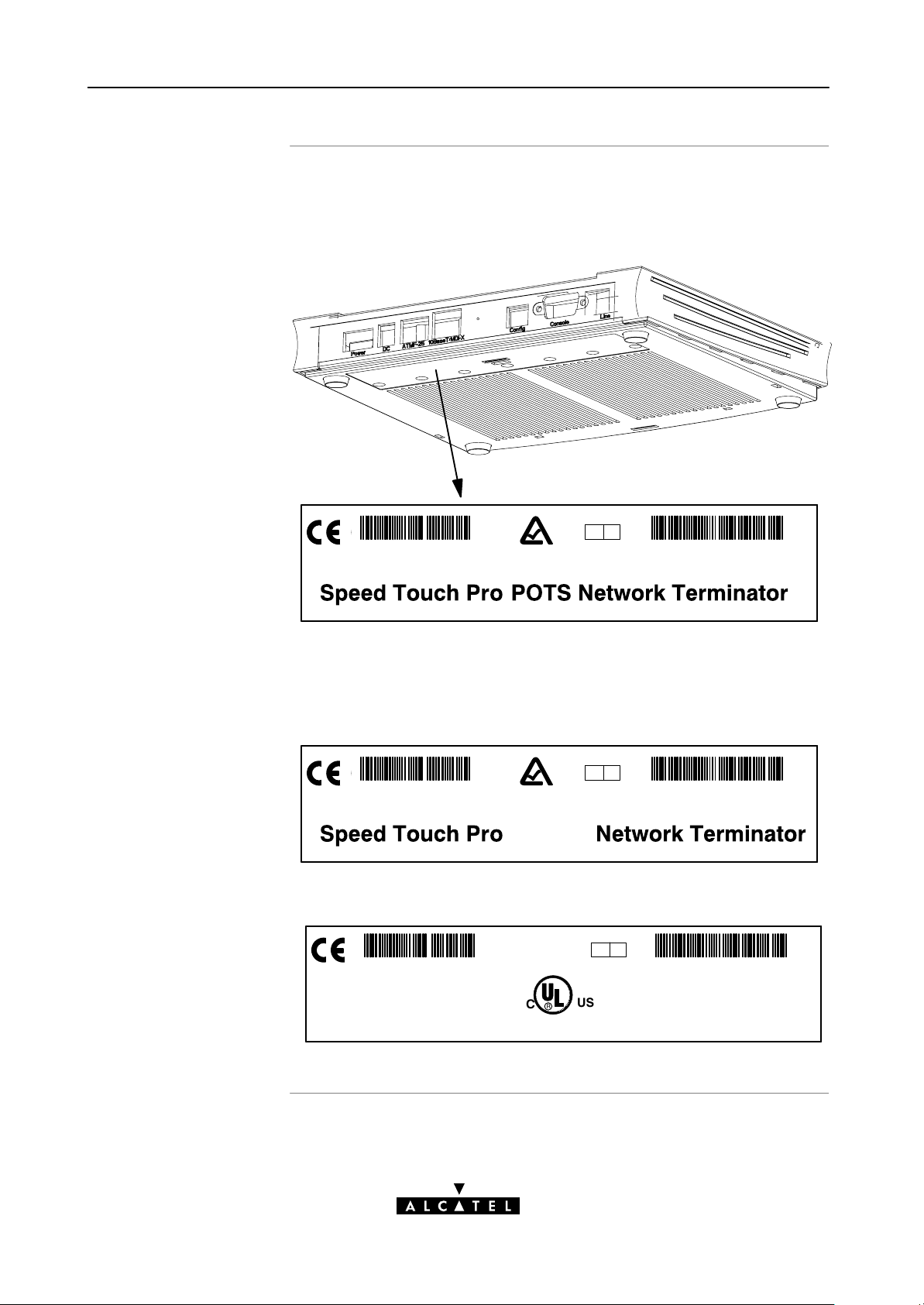
Identify your variant
Use only the STPro variant which is appropriate for the DSL
service delivered to your local premisses.
Therefore, firstly identify your STPro via the marking label on the
bottom:
Q A
CPYYWWNNNNN
MODEL NUMBER:
AA013EC 18704BC
In the figure above, an example is provided of the marking label
for a ADSL/POTS STPro variant.
For the SHDSL STPro variant the marking label is similar to the
example below:
Q A
CPYYWWNNNNN
MODEL NUMBER:
AA013EC 18704BC
SHDSL
The NorthAmerican market uses exclusively ADSL/POTS or SHDSL
variants. The marking label is similar to the example below:
Speed Touch Pro NT Tested to Comply with
FC
FCC rules Part 15 and Part 68
FOR HOME OR OFFICE USE
C
FCC ID: 6VUBEL–35680–DL–N
Made in: Country
REN:<0.1
CP992300XXX
Q A
R
LISTED
US
PART BY ONE OR MORE OF THE FOLLOWING U.S. PATENTS:
C
I . T . E . E168438
PART OF A SYSTEM THAT IS COVERED IN WHOLE OR IN
MODEL NUMBER:
3EC 18204BC
5,636,253.5,633,817.5,657,355.5,903,612.5,867,528
5,951,660.6,044,151.6,072,810.6,088,386.6,105,084
AA01
14 / 288
3EC 36231 ABAA TCZZA Ed. 01
Page 15

1.2 Speed Touch Installation
1 Speed Touch Quick Guide
Aim of this section
In this section
Execution of the steps in this section will bring you on the Internet
in no time.
Topic See
What you Need 1.2.1
STPro Wiring 1.2.2
Check your SP's Service Offerings 1.2.3
Select an STPro Packet Service 1.2.4
Configure your STPro (If Necessary) 1.2.5
Surf the Internet 1.2.6
Detailed STPro Information 1.2.7
3EC 36231 ABAA TCZZA Ed. 01
15 / 288
Page 16

1 Speed Touch Quick Guide
1.2.1 What you Need
DSL service
Ethernet port(s)
Depending on the STPro variant you purchased, the following DSL
service must be available at your local premisses:
ADSL service must be enabled on your telephone line.
As both telephone and ADSL service are simultaneously
available from the same copper pair, you need a central
splitter or distributed filters for decoupling ADSL and
telephone signals.
SHDSL service must be enabled on a dedicated singlepair
copper line.
Contact your SP for more information.
To use the Ethernet port(s) you need at least:
One PC with an Ethernet 10BaseT PCNetwork Interface
Card (NIC) installed
For local networking, a 10BaseT hub (if needed) and the
necessary connection cables.
To use the (optional) ATMF25.6 port you need:
A PC with an ATMF25.6 PCNIC installed
Accessing the STPro
For ATM networking, a workgroup ATM switch.
For local configuration via HTTP/HTML, you need:
A TCP/IP protocol suite
A Web browser.
For native Command Line Interface (CLI) access you need:
A serial cable
An ASCII terminal (VT100) or a PC with ASCII terminal
emulation.
16 / 288
3EC 36231 ABAA TCZZA Ed. 01
Page 17

1.2.2 STPro Wiring
1 Speed Touch Quick Guide
You must wire
Ethernet port(s)
(10BaseT)
Optional ATMF25.6
port (ATMF25)
DSL port (Line)
The Ethernet Port(s) (10BaseT)
The Optional ATMF25.6 Port (ATMF25)
The DSL Port (Line)
The Power Port (DC).
Use the included LAN cable to wire your PC's Ethernet port to
STPro's Ethernet interface.
Refer to section 2.2 for more information.
Use the included LAN cable to wire your PC's ATMF25.6 port to
the STPro's ATMF25.6 port.
Refer to section 2.3 for more information.
Use the included DSL cable to wire the STPro's Line port to your
DSL wall outlet.
Power port (DC)
Refer to section 3.2 for more information.
Firstly check whether the included mains adapter suits the local
power specifications. If you are not sure of the regional power
conditions, check the adapter's specifications in section B.5 and
contact your local power company.
Plug the adapter's coaxial jack into the STPro's receptacle marked
'DC'.
Refer to section 3.3 for more information.
3EC 36231 ABAA TCZZA Ed. 01
17 / 288
Page 18
1 Speed Touch Quick Guide
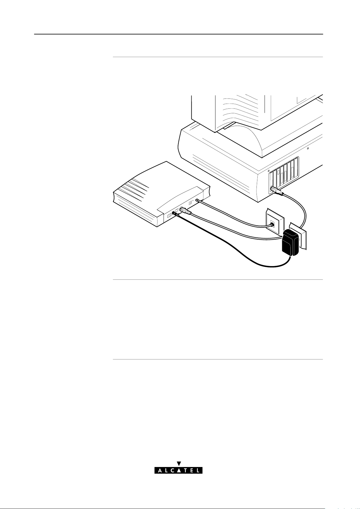
Check your wiring
Once all connections are made the result should look similar as
below:
Turn on your STPro
Once all previous steps are completed, turn on your STPro.
The AST520 is ready for service as soon as the startup
procedures are completed, the Power On Self Test (POST) is
passed and both Power/Alarm and Line Sync LEDs on the front
panel are constantly lit green.
Refer to section B.2 for more information.
18 / 288
3EC 36231 ABAA TCZZA Ed. 01
Page 19

1 Speed Touch Quick Guide
1.2.3 Check your Service Provider's Offering
Service Offering
The SP provides at least the following information:
The VPI/VCI of the Virtual Channel (VC) to use on the DSL
line
The Connection Service supported on this VC
The Encapsulation Method (if different from the Connection
Service's default encapsulation).
Example:
VPI/VCI = 0/35
Connection Service = ETHoA (RFC1483/Br)
Encapsulation Method : ETHoA default, i.e. LLC/SNAP
Your STPro supports multiple simultaneous VCs on the DSL line. If
your SP exploits this capability, he will provide this information per
VC.
Default STPro VPI/VCI
settings
The VPI/VCI value of the default configured VCs are listed in
Appendix C.
In the event that the provided VPI/VCI differ with the STPro
defaults, you can change VC settings via the STPro pages.
See section 13.3 for more information.
3EC 36231 ABAA TCZZA Ed. 01
19 / 288
Page 20

1 Speed Touch Quick Guide
gg
1.2.4 Select an STPro Packet Service
Connection service
As soon as you know the Connection Service on a VC, you can
attach a Packet Service to it.
Following combinations are possible:
Connection Service Protocol(s) Packet Service
ETHoA RFC1483 Bridging Transparent Bridging
Routed Ethernet
Bridged PPPoE (*)
Routed PPPoE
PPPoA RFC2364 Relayed PPPoA (**)
Routed PPPoA
PPPtoDHCP Spoofing
IPoA RFC1483 Routing
RFC1577/RFC2225 CIP
(*) A PPPoE Client application must be installed on your PC.
(**) A PPTP DialUp application must be installed on your PC.
CIP & IP Routing
Selection criteria
For more information on the criteria to prefer one Packet Service
over the other, see chapter 5.
20 / 288
3EC 36231 ABAA TCZZA Ed. 01
Page 21

1.2.5 Configure your STPro (If Necessary)
1 Speed Touch Quick Guide
STPro access
STPro configuration
In most cases your STPro provides instant Internet connectivity as
it features well chosen defaults
In exceptional cases additional or advanced configurations are
desired, the STPro offers various access methods:
Its web interface (See chapter 21)
A Telnet CLI session (See subsection 22.2.1)
A Serial CLI session (See subsection 22.2.2).
Configure the STPro via its web interface.
Most STPro topics have a dedicated page, e.g. for Bridging, PPP,
CIP, NAT, DHCP, etc.
Context related Help pages provide detailed information.
For profound configurations use the Command Line Interface
(CLI).
3EC 36231 ABAA TCZZA Ed. 01
21 / 288
Page 22

1 Speed Touch Quick Guide
1.2.6 Surf the Internet
Finishing setup
Access methods
Alwayson access
Dialin access
After wiring (and optionally configuring) the STPro you are ready
to surf the Internet.
Depending on the selected packet service(s), there is:
AlwaysOn Access
DialIn Access.
With Transparent Bridging, Routed Ethernet and CIP & IP Routing,
no connection procedure is needed. Turn on the STPro and you
are online.
Note: Although no access procedure is needed, some SPs require
authentication before granting accesss to their resources.
A main feature of the STPro is support for traditional Dialin
connectivity to a Remote Access Server (RAS) via its Bridged PPPoE,
Routed PPPoE, Relayed PPPoA and Routed PPPoA packet services.
Manually establish a connection via the STPro pages or via
Operating System (OS) dependent dialin applications.
Most dialin procedures require a user name and password for
identification and authentication.
22 / 288
3EC 36231 ABAA TCZZA Ed. 01
Page 23

1.2.7 Detailed STPro Information
1 Speed Touch Quick Guide
The STPro is more than
just" a DSL router
Use the following parts to explore STPro's advanced features:
Alcatel Speed Touch Quick Guide
Alcatel Speed Touch Wiring Guide
Ethernet and ATMF25.6 2
DSL, Power and Console 3
Resumé 4
Alcatel Speed Touch Configuration and Use
Packet Services 5
Transparent Bridging 6
Routed Ethernet 7
Bridged PPPoE 8
Routed PPPoE 9
1
Relayed PPPoA 10
Routed PPPoA 11
CIP & IP Routing 12
Alcatel Speed Touch Networking
ATM 13
IP 14
DNS 15
3EC 36231 ABAA TCZZA Ed. 01
23 / 288
Page 24

1 Speed Touch Quick Guide
Alcatel Speed Touch Network Security
NAT & PAT 16
Firewalling 17
Alcatel Speed Touch Maintenance
Alcatel Speed Touch Software 18
Alcatel Speed Touch Password 19
Alcatel Speed Touch ToDefaults 20
Alcatel Speed Touch Web Interface 21
Alcatel Speed Touch CLI 22
Alcatel Speed Touch Appendices
Abbreviations
Alcatel Speed Touch Troubleshooting A
Alcatel Speed Touch Specifications B
Alcatel Speed Touch Default Assignments C
Alcatel Speed Touch Safety and Regulatory Notices D
24 / 288
3EC 36231 ABAA TCZZA Ed. 01
Page 25

Alcatel
Speed Touch
with Firewall
Wiring Guide
3EC 36231 ABAA TCZZA Ed. 01
25 / 288
Page 26

26 / 288
3EC 36231 ABAA TCZZA Ed. 01
Page 27

2 Wiring Guide - Ethernet and ATMF25.6
2 Wiring Guide - Ethernet and ATMF25.6
In this chapter
Topic See
LAN Cables 2.1
Connecting Ethernet 2.2
Connecting ATMF25.6 (Optional) 2.3
Ethernet vs. ATMF25.6 Connectivity 2.4
3EC 36231 ABAA TCZZA Ed. 01
27 / 288
Page 28

2 Wiring Guide - Ethernet and ATMF25.6
2.1 LAN Cables
Included LAN cable
Using LAN cables
LAN cable types vs.
port types
In your STPro package, a full wired straightthrough RJ45/RJ45
cable, further referred to as LAN cable is included.
You can use LAN cables other than the one provided in the box,
e.g. crossover LAN cables. However, make sure that these have
the correct layout.
See section B.6 for more information on how to identify
straightthrough and crossover LAN cables.
Note: As the included LAN cable is fully wired, it can also be used for
connecting the STPro's ATMF25.6 port.
Determine the LAN cable type from the following table:
Speed Touch Other equipment Type of LAN cable Symbol
MDIX MDIX Crossover
MDI Straightthrough
Equipment and ports
ATMNetwork ATMNetwork Crossover
ATMEnd Straightthrough
PC Ethernet ports are always of type MDI; ATM PCNIC ports are
always of type ATMEnd.
Ethernet hub ports are of type MDIX; ATM switch ports are of type
ATMNetwork.
Note: You may use the (switchable) uplink" or cascade" MDI port which is
sometimes present on Ethernet hubs. However, make sure to use the correct
cable type.
28 / 288
3EC 36231 ABAA TCZZA Ed. 01
Page 29

2.2 Connecting Ethernet
2 Wiring Guide - Ethernet and ATMF25.6
In this section
Topic See
Ethernet Port(s) on your STPro 2.2.1
Single PC Ethernet Wiring 2.2.3
LAN Ethernet Wiring 2.2.3
3EC 36231 ABAA TCZZA Ed. 01
29 / 288
Page 30
2 Wiring Guide - Ethernet and ATMF25.6
Activity
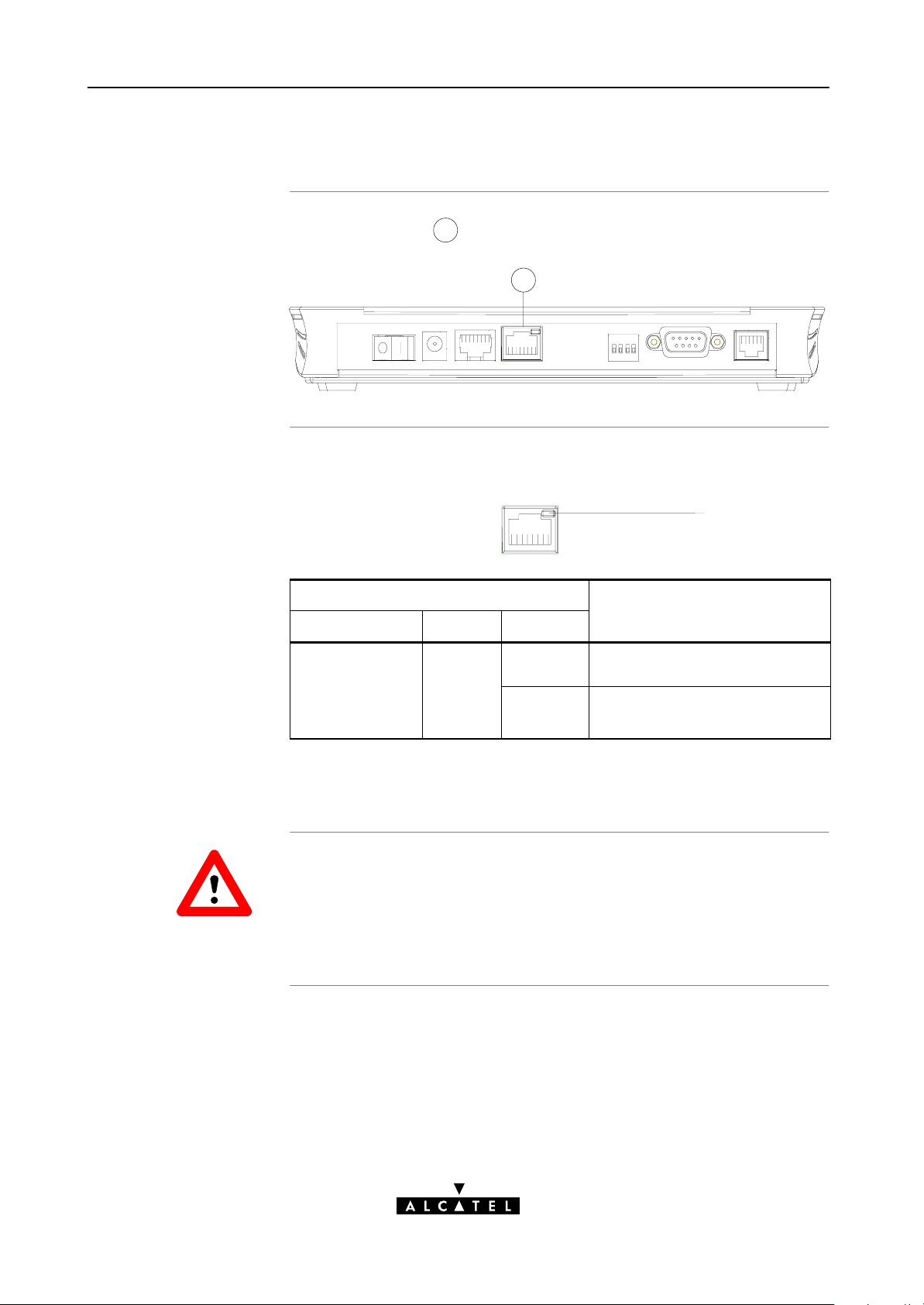
2.2.1 Ethernet Port on the single Ethernet port Model
Ethernet interface
Ethernet port LED
The Ethernet port
1
of the STPro is a 10BaseT Half Duplex
Ethernet interface of type MDIX:
1
The Ethernet port on the rear panel has a LED:
Link Integrity LED
10Base T/MDI-X
Indicator
Name Color State
Integrity
Green Off No connection on this Ethernet
Description
port.
CAUTION
On Ethernet link up.
No activity on this Ethernet port.
If the STPro and other LAN device(s) are properly connected and
powered on, the green LED lights up.
10BaseT Half Duplex Interfacing
Make sure the 10BaseT port(s) of your PC(s) are configured for
either Auto Negotiation or Half Duplex.
Never configure the 10BaseT Ports for FullDuplex !
30 / 288
3EC 36231 ABAA TCZZA Ed. 01
Page 31

2 Wiring Guide - Ethernet and ATMF25.6
Activity
2.2.2 Ethernet Ports on the Ethernet Hub Model
Ethernet interfaces
Ethernet port(s) LED
Each Ethernet port
1
of the STPro is a 10BaseT Half Duplex
Ethernet interface of type MDIX:
1 1 1 1
Each Ethernet port on the rear panel has a LED:
Link Integrity/Activity LED
10Base T/MDI-X
Indicator
Name Color State
Integrity
Green Off No connection on this Ethernet
Description
port.
CAUTION
On Ethernet link up.
No activity on this Ethernet port.
Flashing Data is flowing from/to this
Ethernet port.
If the STPro and other LAN device(s) are properly connected and
powered on, the particular green LED lights up.
10BaseT Half Duplex Interfacing
Make sure the 10BaseT port(s) of your PC(s) are configured for
either Auto Negotiation or Half Duplex.
Never configure the 10BaseT Ports for FullDuplex !
3EC 36231 ABAA TCZZA Ed. 01
31 / 288
Page 32

2 Wiring Guide - Ethernet and ATMF25.6
2.2.3 Single PC Ethernet Wiring
Single PC configuration
Procedure
In this configuration the STPro is connected to a single PC. Your
LAN" consists of only one PC and the STPro.
Proceed as indicated in the following figure to connect your STPro
to a single PC:
MDI
10 BaseT
MDIX
32 / 288
3EC 36231 ABAA TCZZA Ed. 01
Page 33

2.2.4 LAN Ethernet Wiring
2 Wiring Guide - Ethernet and ATMF25.6
Procedure
Proceed as indicated in the following figure to make the
connections for a LAN (STPro hub specific connections are shaded
gray):
MDI
MDI
MDI
MDI
MDI
MDI
Hub
MDIX
10 BaseT
MDIX
CAUTION
MDI vs. MDIX hub
ports and the STPro
3EC 36231 ABAA TCZZA Ed. 01
Cascading Repeating Hubs
You may cascade up to four repeating hubs in your LAN
(limitations of Repeating Ethernet V2.0/IEEE802.3 hubs). In case
more hubs need to be cascaded, you must use switching hubs.
In the above figure an MDIX port on the hub connects to the
STPro. Therefore, a crossover LAN cable is used.
Note: In case the hub's uplink" port is used to wire the STPro you can use the
included straightthrough LAN cable.
33 / 288
Page 34

2 Wiring Guide - Ethernet and ATMF25.6
2.3 Connecting the ATMF25.6 Port (Optional)
Check your STPro
model
ATMF25.6 port
Procedure
This connection procedure applies solely to the dual port STPro
model.
The ATMF25.6 port on the single Ethernet port STPro model is an
ATM Forum 25.6 Mbit/s compliant interface of type ATM Network
Equipment"; the PCNIC's ATMF25.6 port is of type ATM End
Equipment".
Proceed as indicated in the following figure to connect the STPro
ATMF25.6 port to your PC's ATMF25.6 PCNIC using the
included straightthrough LAN cable:
34 / 288
ATM
ATMF
3EC 36231 ABAA TCZZA Ed. 01
Page 35

2 Wiring Guide - Ethernet and ATMF25.6
2.4 Ethernet vs. ATMF25.6 Connectivity
Ethernet port(s)
ATMF25.6 port
Concurrent use of both
ports
Due to its inherent support for networking, Ethernet will be your
natural choice for creating a small LAN.
The (optional) ATMF25.6 port provides excellent protocol
transparency and native ATM application support.
The dual port STPro model is designed for the concurrent use of
both Ethernet and ATMF25.6 ports. Networking configurations
remain equally valid if the ports are used simultaneously.
There is no performance penalty on this simultaneous use except
for the sharing of the upstream and downstream DSL bandwidth.
3EC 36231 ABAA TCZZA Ed. 01
35 / 288
Page 36

2 Wiring Guide - Ethernet and ATMF25.6
36 / 288
3EC 36231 ABAA TCZZA Ed. 01
Page 37

3 Wiring Guide - DSL, Power and Console
3 Wiring Guide - DSL, Power and Console
In this chapter
Topic See
Locating Ports 3.1
Connecting the DSL Port 3.2
Connecting the Power Adapter 3.3
Connecting the Serial Port (Optional) 3.4
3EC 36231 ABAA TCZZA Ed. 01
37 / 288
Page 38
3 Wiring Guide - DSL, Power and Console
3.1 Locating Ports
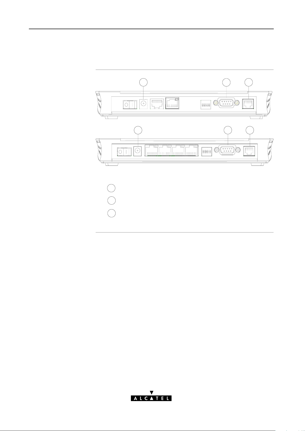
Port description
4
4
Following ports are used:
: DSL line port, marked LINE"
3
: Power socket, market DC"
4
: Serial port, marked Console".
5
5
5
3
3
38 / 288
3EC 36231 ABAA TCZZA Ed. 01
Page 39

3.2 Connecting the DSL Port
3 Wiring Guide - DSL, Power and Console
ADSL vs. SHDSL
Procedure
In the case of:
ADSL Service
A central splitter, or distributed filters for decoupling ADSL
and POTS or ISDN signals must be installed on your
telephone line or telephone wall outlets. In some cases
crossover adapters might be required.
SHDSL Service
As SHDSL service is delivered on dedicated wall outlets, no
splitters or filters are needed. In some cases crossover
adapters might be required.
Proceed as indicated in the following figure to connect the STPro
to the DSL line using the included black DSL cable:
Line
DSL Cable
3EC 36231 ABAA TCZZA Ed. 01
39 / 288
Page 40

3 Wiring Guide - DSL, Power and Console
3.3 Connecting the Power Adapter
Introduction
Power adapter types
Procedure
The STPro is delivered with a modular external power adapter
converting the AC mains to 9VDC/1A unregulated output voltage.
Check if the power adapter included in the STPro package is
compatible with your local electrical power specifications.
See section B.5 for connector layout and output specifications.
If you are not sure of the specifications of your local mains power,
contact your local product dealer for more information.
Proceed as follows to connect the power supply adapter :
40 / 288
DC
3EC 36231 ABAA TCZZA Ed. 01
Page 41

3 Wiring Guide - DSL, Power and Console
3.4 Connecting the Serial Port (Optional)
Serial access
Requirements for using
the serial access
Procedure
Like most routers, the STPro carries a serial port on its back
panel, featuring access from a remote host via a modem
connection or local access from a terminal.
For access via the serial port, you must have the following:
A serial cable
An ASCII terminal (VT100) or a workstation/PC with ASCII
terminal emulation or emulation application for local
configuration via the CLI
or
A POTS or ISDN modem for remote configuration of the
STPro via the CLI.
Proceed as follows to connect the STPro serial port:
Step Action
1 Locate the serial port on the STPro back panel.
See appendix B for more information.
2 Connect the serial cable to the STPro serial port.
3 Connect the other end of the serial cable to the serial
interface of the (emulated) ASCII terminal or modem.
3EC 36231 ABAA TCZZA Ed. 01
41 / 288
Page 42

3 Wiring Guide - DSL, Power and Console
42 / 288
3EC 36231 ABAA TCZZA Ed. 01
Page 43

4 Wiring Guide - Resumé
4 Wiring Guide - Resumé
After wiring
The following illustrations show some of the wiring configurations
possible for the STPro once all of the connections have been
made:
3EC 36231 ABAA TCZZA Ed. 01
43 / 288
Page 44

4 Wiring Guide - Resumé
44 / 288
3EC 36231 ABAA TCZZA Ed. 01
Page 45

Alcatel
Speed Touch
with Firewall
Configuration and Use
3EC 36231 ABAA TCZZA Ed. 01
45 / 288
Page 46

46 / 288
3EC 36231 ABAA TCZZA Ed. 01
Page 47

5 Configuration and Use - Packet Services
5 Configuration and Use - Packet Services
In this chapter
Topic See
Supported Packet Services 5.1
Packet Services at a Glance 5.2
Selection Criteria 5.3
3EC 36231 ABAA TCZZA Ed. 01
47 / 288
Page 48

5 Configuration and Use - Packet Services
5.1 Supported Packet Services
What is a packet
service ?
Eight packet services
Multiprotocol
Packet services are the core functions of the STPro. They provide
that frames or packets get forwarded from the LAN side towards
the DSL line and vice versa.
Transparent Bridging
Routed Ethernet
Bridged PPPoE
Routed PPPoE
Relayed PPPoA
Routed PPPoA
Classical IP & IP Routing
ATM cell switching (*).
(*) Requires the ATMF25.6 port.
All examples in this User's Guide are based on the Internet
Protocol (IP) suite.
Examples in this User's
Guide
However, the STPro DSL router is a true multiprotocol device: it
can easily handle most other popular protocol suites
This User's Guide presents typical configurations but as an
experienced user you are free to experiment and find an optimal
configuration.
48 / 288
3EC 36231 ABAA TCZZA Ed. 01
Page 49

5 Configuration and Use - Packet Services
5.2 Packet Services at a Glance
Access methods
The STPro supports two access methods:
Direct access
Once initial configuration is done, continuous and immediate
access is available via the DSL line.
For direct access use either of:
Transparent Bridging
Routed Ethernet
CIP & IP Routing.
Dialin access
In this mode access must be explicitly established, e.g. by
dialing" into a Remote Access Server (RAS).
For dialin access use either of:
Bridged PPPoE
Routed PPPoE
Relayed PPPoA
Routed PPPoA.
Forwarding methods
As their names imply the packet services can be differentiated in
two groups:
Forwarding packet services:
Transparent Bridging
Bridged PPPoE
Relayed PPPoA.
These packet services forward frames unmodified.
Routing packet services:
Routed Ethernet
Routed PPPoE
Routed PPPoA
CIP & IP Routing.
These packet services, combined with NA(P)T allow to share a
single IP address amongst multiple users on the LAN.
3EC 36231 ABAA TCZZA Ed. 01
49 / 288
Page 50

A
5 Configuration and Use - Packet Services
Transparent Bridging
Routed Ethernet
PPPoE
The STPro IEEE802.1D Transparent Bridging packet service (further
referred to as Bridging) offers complete protocol transparency and
has inherent configuration simplicity. Yet it provides excellent
forwarding performance.
The STPro RFC1483 Routed Ethernet packet service (also referred
to as MAC Encapsulated Routing (MER)) relies on standard IP
Routing for its forwarding. However, prior to output IP packets on
the DSL line they are wrapped in Ethernet frames.
By doing so there is no apparent difference for the remote access
server between frames sourced by a bridge and those sourced by
the STPro MER entity.
PPPoE is one of two popular mechanisms to get in touch with the
SP.
Bridged PPPoE
By installing a PPPoE client application (provided by your SP.)
on your PC(s) and by using the STPro's bridge, connectivity
can be established.
PPPo
Routed PPPoE
PPPoE SP access can equally be accomplished by the
embedded PPPoE client of the STPro.
The other method to get in touch with the SP over the DSL line is
PPPoA.
Relayed PPPoA
Similar to Bridged PPPoE this requires installation of a PPTP
dialin application (*) on your PC(s).
Routed PPPoA
PPPoA SP access can equally be accomplished by the
embedded PPPoA dialin client of the STPro.
(*) Most popular OSs have a PPTP dialin application installed, e.g. Microsoft
DialUp Networking or support PPTP Tunneling software to be installed.
50 / 288
3EC 36231 ABAA TCZZA Ed. 01
Page 51

5 Configuration and Use - Packet Services
CIP & IP Routing
Packet services resumé
The STPro IP router can also be combined with Classical IP (CIP).
Classical IP is a mature technique for creating classical IP networks
on top of ATM technology. It is widely supported by most, if not all
remote access routers.
Although not the original aim of Classical IP it is mostly used for
connecting routers over wide area pointtopoint links.
All STPro's packet services can be summarized as follows:
Port Packet
Service
10BaseT Bridging n 1 per user Multiprotocol
Ethernet
Routed Ethernet n 1 (via NAPT) IP Suite
Bridged PPPoE n 1 per user Multiprotocol (*)
Routed PPPoE n 1 (via NAPT) IP Suite
Relayed PPPoA 1 1 per user Multiprotocol (*)
Routed PPPoA n 1 (via NAPT) IP Suite
CIP n 1 (via NAPT) IP Suite
User/VC IP Address Protocol
Detailed packet service
use description
ATMF25.6
(optional)
(*) The supported protocol(s) depend on the provisioning by the session client
application, e.g. IP, IPX and NETBEUI for Microsoft's DialUp Networking
application for Relayed PPPoA.
ATM Cell Switching
The functionality of ATM Cell switching depends on the
capabilities, offered by the drivers included with the ATMF25.6
PCNIC.
For more information on the configuration and use of all of the
STPro packet services, see for:
Transparent Bridging: chapter 6
Routed Ethernet: chapter 7
Bridged PPPoE: chapter 8
Routed PPPoE: chapter 9
Relayed PPPoA: chapter 10
Routed PPPoA: chapter 11
CIP & IP Routing: chapter 12.
3EC 36231 ABAA TCZZA Ed. 01
51 / 288
Page 52

5 Configuration and Use - Packet Services
5.3 Selection Criteria
In this section
Selection criteria
Simultaneous use of
packet services
Selection Criteria
Simultaneous Use of Packet Services.
The criteria below can help you to select the most appropriate
packet service for your application:
The configuration required by your SP
The application protocol you wish to use (within the
boundaries of the remote end)
The access method: an AlwaysOn" connection or a
connection that is established when needed, i.e. DialIn"
Connectivity to a single or multiple remote networks
Security features such as identification, authentication,
encryption, NA(P)T and Firewalling
DSL modem vs DSL gateway model.
All packet services can be active at the same time without any
restriction. The STPro can manage any combination of the packet
services simultaneously up to a maximum number of 12
configured virtual connections.
52 / 288
Note: For Transparent Bridging (including Bridged PPPoE) the maximum
number of configured Bridging ports is four.
3EC 36231 ABAA TCZZA Ed. 01
Page 53

6 Configuration and Use - Transparent Bridging
6 Configuration and Use - Transparent Bridging
Introduction
See also
In this chapter
Transparent Bridging is the packet service of your choice as it:
Is platform and OS independent
Is true multiprotocol
Has no performance limitations in the Alcatel implementation
Has almost no constraints on the number of attached users.
Routed Ethernet packet service in chapter 7.
Topic See
Preparatory Steps 6.1
Using Bridging 6.2
Bridging Configuration 6.3
Bridge Data 6.4
3EC 36231 ABAA TCZZA Ed. 01
53 / 288
Page 54

6 Configuration and Use - Transparent Bridging
6.1 Preparatory Steps
Needed information
Multiple destinations
PC(s)
VPI/VCI value of the VC(s) to use on the DSL line
ETHoA (RFC1483/Bridged) connection service must be
supported on these VCs
Encapsulation method (LLC/SNAP)
The PC's IP configuration: static or dynamic (DHCP).
Note: The RFC1483 is updated by RFC2684. The STPro fully complies with the
relevant sections in both RFCs.
You can attach up to four connections (VCs ) to the bridge.
To conserve DSL upstream bandwidth do not attach more
connections than needed.
Bridging does not impose specific requirements to your PC's
protocol layers. However, make sure that these are properly
installed and configured.
In all subsequent examples, TCP/IP will be used.
54 / 288
TCP/IP
CAUTION
For TCP/IP, your SP will assign either static IP parameters or will
ask to enable DHCP (per PC).
Transparent Bridging and DHCP
If the SP requires you to use DHCP on your local PC(s), you must
disable the STPro DHCP server.
This is to avoid conflicts between two DHCP servers.
See section 14.4 for more information.
3EC 36231 ABAA TCZZA Ed. 01
Page 55

6.2 Using Bridging
6 Configuration and Use - Transparent Bridging
Bridging configuration
Using Bridging
There are no default Bridging entries.
Therefore, configure an appropriate entry as follows:
1. If needed, add an ETHoA phonebook entry with the correct
VPI/VCI on the 'Phonebook' page.
2. On the 'Bridge' page, select this phonebook entry from the
'Address' popdown list.
3. For this entry, select the correct encapsulation method from
the 'Encapsulation' popdown list.
4. Click
See section 6.3 for more information.
Make sure your STPro is turned on first.
Turn on your PC(s), start your Web browser and you are on the
Internet or have Corporate Intranet access.
Although the access method of the bridge is 'Alwayson', the
remote organization might ask for a user name and password.
.
3EC 36231 ABAA TCZZA Ed. 01
55 / 288
Page 56

6 Configuration and Use - Transparent Bridging
6.3 Bridging Configuration
Introduction
In this section
The 'Bridge' page
This section describes the use of the STPro 'Bridge' page.
The 'Bridge' Page
The 'Bridging Ports' Table
'Bridging Ports' Table Components
The 'Aging' Box
Adding Entries
Deleting Entries.
Click in the left pane of the STPro pages to pop up the
'Bridging' page (See section 21.2 for more information):
56 / 288
3EC 36231 ABAA TCZZA Ed. 01
Page 57
6 Configuration and Use - Transparent Bridging
The 'Bridging Ports'
table
'Bridging Ports' table
components
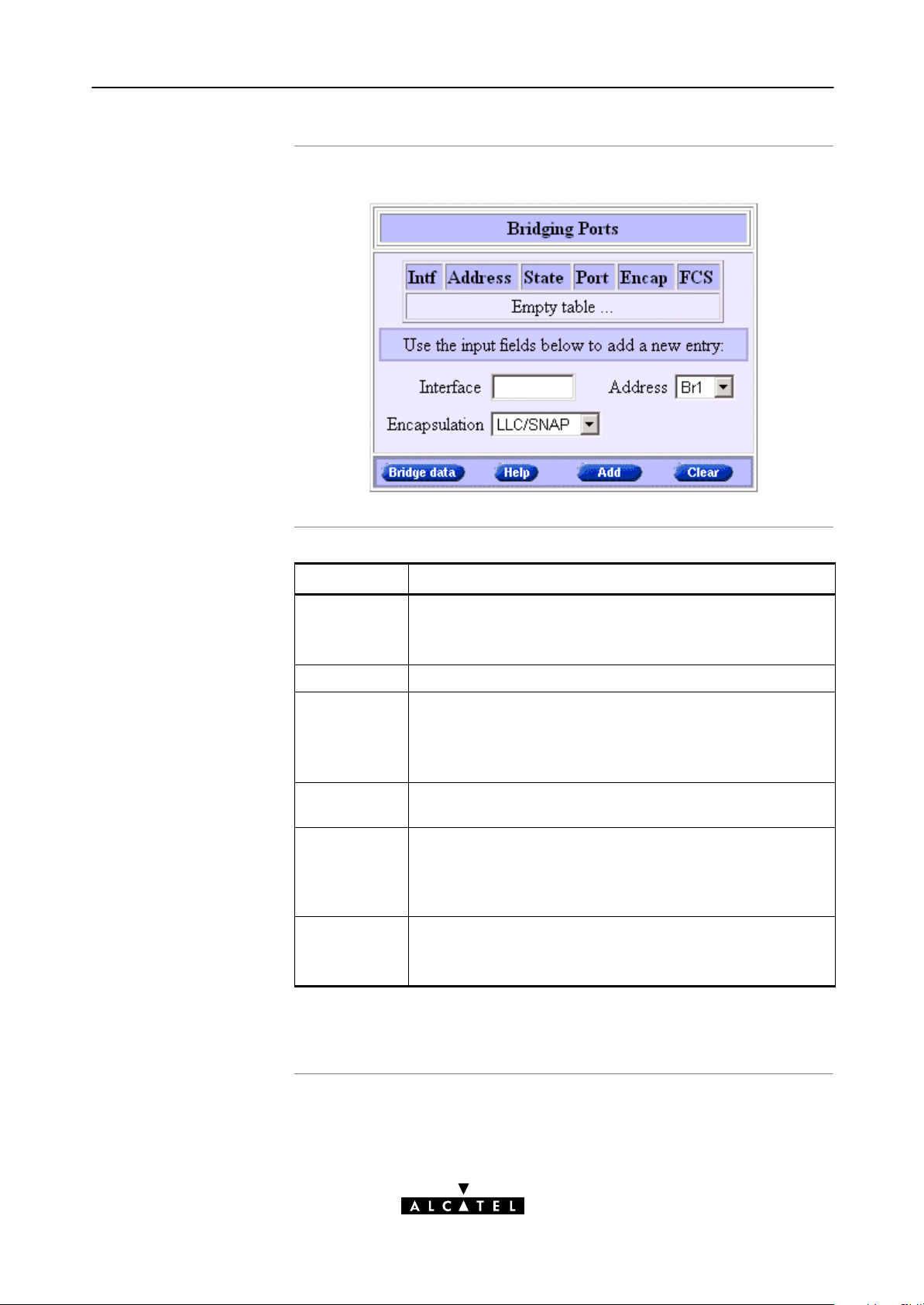
The following figure shows the 'Bridging Ports' table:
Field Description
Intf
Indicates the interface name for the Bridging entry.
Interface
Address Indicates the phonebook entry used by the Bridging entry.
State
Port Indicates the name of the Bridge port on the WAN side:
Encap
Encapsulation
FCS Indicates whether the last four bytes of the Ethernet frames
(*) Ethernet frames are also referred to as Medium Access Control (MAC)
frames or IEEE802.3 frames.
Note: In most cases, the interface name will be the same as
the phonebook entry name.
Indicates the state of the Bridging entry.
Note: Unless the interface is created via the CLI, Bridging
entries are always in state connected, i.e. attached to a
Bridge port.
wan0, wan1, wan2, ...
Indicates the applied encapsulation method for Ethernet
frames(*) on the VC.
The STPro supports both the LLC/SNAP method (default) and
the VCMUX method.
are preserved or not. By default the FCS is set to NO.
Note: You can set the FCS to YES via the CLI.
3EC 36231 ABAA TCZZA Ed. 01
57 / 288
Page 58

x
6 Configuration and Use - Transparent Bridging
The 'Aging' bo
Adding entries
The following figure shows the 'Aging' box:
It indicates the aging timer of the bridge internal database.
If the aging time of a MAC entry has expired this entry will be
removed from the database.
Only in exceptional cases the default value of 300 seconds (5
minutes) needs to be modified. The allowed range is from 10
seconds to 12 days.
Proceed as follows:
1. Browse to the 'Bridge' page.
Deleting entries
2. If needed, click .
3. Select the phonebook entry from the 'Address' popdown list.
Note: In case the presented phonebook entries do not suite your desired
configuration, you must firstly create a correct phonebook entry. See
section 13.3 for more information.
4. Select the encapsulation method for the Bridging port from
the 'Encapsulation' popdown list (per default set to
LLC/SNAP).
5. Optionally, enter a name for the Bridge interface in the
'Interface' field.
6. Click and to finish the procedure.
On the 'Bridge' page, click next to the Bridging entry you
want to delete. As a result your selection is highlighted.
Click
and .
58 / 288
3EC 36231 ABAA TCZZA Ed. 01
Page 59

6.4 Bridge Data
6 Configuration and Use - Transparent Bridging
Introduction
The 'Bridge Data' page
Transparent Bridging completely relies on its filtering database for
its frame forwarding through the bridge. This filtering database is
accessible via the 'Bridge' page and allows you to overview all
current MAC entries.
Click on the 'Bridge' page to pop up the 'Bridge Data'
page:
Available 'Bridge
Data' tables
3EC 36231 ABAA TCZZA Ed. 01
All MAC entries are spread over 3 tables:
The 'static MAC addresses' table
The 'permanent MAC addresses' table
The 'dynamic MAC addresses' table.
59 / 288
Page 60

6 Configuration and Use - Transparent Bridging
Static MAC addresses
Permanent MAC
addresses
This table lists the MAC addresses you have added to the filtering
database via the CLI. These MAC addresses will never be aged by
the bridge.
In principle, no static MAC addresses are to be configured.
These are the MAC addresses that must always be resident inside
the bridge, as stipulated in the IEEE802.1D standard:
The STPro's own Ethernet MAC address:
e.g. 00-80-9F-01-02-03
The Broadcast MAC address:
FF-FF-FF-FF-FF-FF
The bridge group MAC address:
01-80-C2-00-00-00
The 16 reserved MAC addresses of IEEE802.1D:
From 01-80-C2-00-00-01
up to 01-80-C2-00-00-0F
The all LANs bridge management group MAC address:
01-80-C2-00-00-10
Dynamic MAC
addresses
This table lists all MAC entries added by the learning process of
the Bridge.
If the aging time of a MAC entry has expired, i.e. its age equals
the time indicated in the 'Aging' box, this entry will be removed
from the list.
60 / 288
3EC 36231 ABAA TCZZA Ed. 01
Page 61

7 Configuration and Use - Routed Ethernet
7 Configuration and Use - Routed Ethernet
Introduction
In this chapter
Routed Ethernet(*) is the packet service of your choice as it:
Is instantly replaceable with an IEEE Transparent Bridge
Provides Alwayson type of connections and is
autoconfigurable if DHCP is enabled
Allows multiple users to share a single IP address if NA(P)T is
enabled
Allows your local network to be shielded from the Internet via
STPro's programmable Firewall.
(*) Is also referred to as MAC Encapsulated Routing (MER).
Topic See
Preparatory Steps 7.1
Using Routed Ethernet 7.2
Routed Ethernet Configuration 7.3
3EC 36231 ABAA TCZZA Ed. 01
61 / 288
Page 62

7 Configuration and Use - Routed Ethernet
7.1 Preparatory Steps
Needed information
Multiple destinations
PC(s)
VPI/VCI value of the VC(s) to use on the DSL line
ETHoA (RFC1483/Bridged) connection service must be
supported on this VC
Encapsulation method (LLC/SNAP)
Whether IP configuration is static or dynamic (DHCP).
The STPro can manage up to 12 Routed Ethernet connections
simultaneously.
Note: Check with your SP or corporate whether multiple endtoend connectivity
is enabled.
In order to use the Routed Ethernet mode of the STPro, the OS on
your PC(s) must support TCP/IP.
See chapter 14 for more information on IP.
62 / 288
3EC 36231 ABAA TCZZA Ed. 01
Page 63

7.2 Using Routed Ethernet
7 Configuration and Use - Routed Ethernet
Routed Ethernet
configuration
Using Routed Ethernet
There are no default Routed Ethernet entries.
Therefore, configure an appropriate entry as follows:
1. If needed, add an ETHoA phonebook entry with the correct
VPI/VCI on the 'Phonebook' page.
2. On the 'MER' page, select this phonebook entry from the
'Address' popdown list.
3. For this entry, select the correct encapsulation method from
the 'Encapsulation' popdown list.
4. DHCP is per default on (). If needed, uncheck it and enter IP
information manually.
5. Click
See section 7.3 for more information.
Make sure your STPro is turned on first.
Turn on your PC(s), start your Web browser and you are on the
Internet or have Corporate Intranet access.
.
Although the access method of Routed Ethernet is 'Alwayson' the
remote organization might ask for a username and password.
3EC 36231 ABAA TCZZA Ed. 01
63 / 288
Page 64

7 Configuration and Use - Routed Ethernet
7.3 Routed Ethernet Configuration
Introduction
In this section
The 'MER' page
This section describes the use of the STPro 'MER' page.
The 'MER' Page
The 'MER Settings' Table
'MER Settings' Table Components
Adding Entries
Deleting Entries.
Click in the left pane of the STPro pages to pop up the
'MER' page (See section 21.2 for more information):
64 / 288
3EC 36231 ABAA TCZZA Ed. 01
Page 65
7 Configuration and Use - Routed Ethernet
The 'MER Settings'
table
'MER Settings' table
components
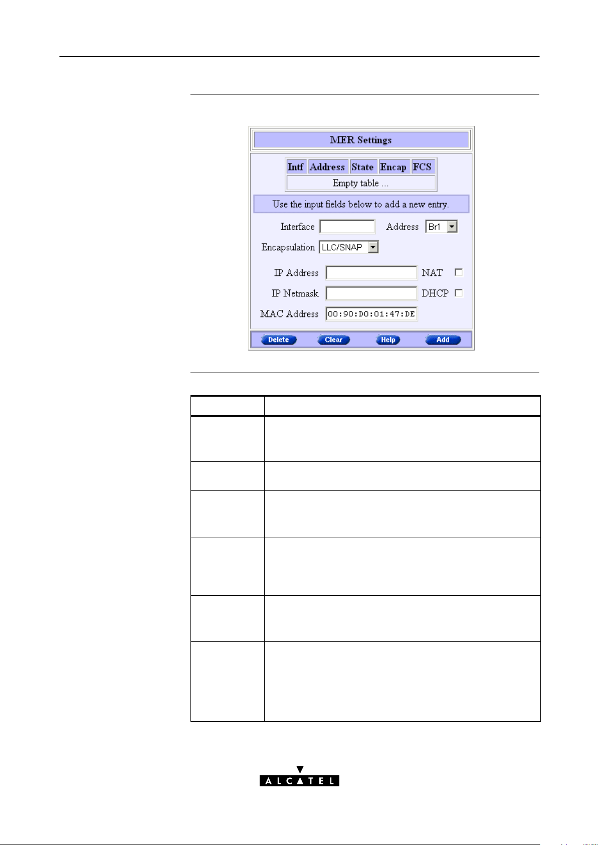
The following figure shows the 'MER Settings' table:
Field Description
Intf
Indicates the interface name for the Routed Ethernet entry.
Interface
Address Indicates the phonebook entry used by the Routed Ethernet
State
Encap
Encapsulation
FCS Indicates whether the last four bytes of the Ethernet frames
IP Address
IP Netmask
Note: In most cases, the interface name will be the same as
the phonebook entry name.
entry.
Indicates the state of the Routed Ethernet interface.
Note: Unless the interface is created via the CLI, Routed
Ethernet entries are always in state connected.
Indicates the applied encapsulation method for Ethernet
frames(*) on the VC.
The STPro supports both the LLC/SNAP method (default) and
the VCMUX method.
are preserved or not. By default the FCS is set to NO.
Note: You can set the FCS to YES via the CLI.
Indicates the negotiated IP address and netmask used by the
Routed Ethernet entry.
In case DHCP is checked () this IP address is dynamically
assigned by the remote DHCP server. If DHCP is unchecked,
you must enter a static IP address for the local side of the
Routed Ethernet connection.
3EC 36231 ABAA TCZZA Ed. 01
65 / 288
Page 66

7 Configuration and Use - Routed Ethernet
Field Description
MAC Address Indicates the MAC address for the Routed Ethernet entry.
NAT Indicates whether NA(P)T is used () or not on the IP address
DHCP Indicates whether DHCP is used () or not for the Routed
(*) Ethernet frames are also referred to as Medium Access Control (MAC)
frames or IEEE802.3 frames.
Note: In case no MAC address is entered manually, the
source MAC address of the Ethernet frames is the STPro
Ethernet MAC address.
of the Routed Ethernet entry.
Ethernet entry.
Adding entries
Proceed as follows:
1. Browse to the 'MER' page.
2. If needed, click
.
3. Select the phonebook entry from the 'Address' popdown list.
Note: In case the presented phonebook entries do not suite your desired
configuration, you must firstly create a correct phonebook entry. See
section 13.3 for more information.
4. Select the encapsulation method for the Bridging port from
the 'Encapsulation' popdown list (per default set to
LLC/SNAP).
5. Optionally, enter the appropriate configuration in one, or
more of the following fields:
The 'Interface' field
The 'IP Address' and 'IP Netmask' fields
The 'MAC Address' field.
6. Optionally, check one or more of the following checkboxes:
The 'NAT' checkbox
The 'DHCP' checkbox.
Deleting entries
66 / 288
7. Click
and to finish the procedure.
On the 'MER' page, click next to the entry you want to delete.
As a result your selection is highlighted.
Click
and .
3EC 36231 ABAA TCZZA Ed. 01
Page 67

8 Configuration and Use - Bridged PPPoE
8 Configuration and Use - Bridged PPPoE
Introduction
See also
In this chapter
The STPro transparent bridge can be used in combination with a
PPP over Ethernet (PPPoE) client installed on your PC.
The resulting Bridged PPPoE packet service provides similar dialin
experience as found on pointtopoint connections.
Routed PPPoE packet service in chapter 9.
Topic See
Preparatory Steps 8.1
Using Bridged PPPoE 8.2
Bridged PPPoE Configuration 8.3
3EC 36231 ABAA TCZZA Ed. 01
67 / 288
Page 68

8 Configuration and Use - Bridged PPPoE
8.1 Preparatory Steps
Needed information
Multiple destinations
PC(s)
VPI/VCI value of the VC(s) to use on the DSL line
ETHoA (RFC1483/Bridged) connection service must be
supported on this VC
Encapsulation method (LLC/SNAP)
Remote access server must be a PPPoE server
PPPoE client to be installed
User name and password for your user account.
Up to four simultaneous Bridged PPPoE sessions can be active.
Note: Per active Bridged PPPoE session a dedicated Bridging entry must be
made available on the STPro. See section 8.3 for more information.
To use Bridged PPPoE, a PPPoE client must be installed on your PC.
The SP will provide the PPPoE client software. Contact him for
more information.
68 / 288
3EC 36231 ABAA TCZZA Ed. 01
Page 69

8.2 Using Bridged PPPoE
8 Configuration and Use - Bridged PPPoE
Creating and using a
PPPoE session instance
Via the PPPoE client, you will be able to create PPPoE session
icons, representing all the connection parameters, just like
creating DialUp icons with Microsoft's DialUp Networking
application.
All you need is your username and password for your account;
although sometimes also a Service Name and/or Access
Concentrator is required.
Check with your SP which Service Name and/or Access
Concentrator to choose, if any.
For further details on how to fill in these parameters and use
additional functionality, consult the User's Guide of your PPPoE
client or follow the instructions of your SP.
3EC 36231 ABAA TCZZA Ed. 01
69 / 288
Page 70

8 Configuration and Use - Bridged PPPoE
8.3 Bridged PPPoE Configuration
Introduction
Bridging configuration
As the Bridged PPPoE packet service implies nothing more than
using the STPro Transparent Bridging packet service, no specific
configuration for Bridged PPPoE is required on the STPro.
However, you may need to configure the Transparent Bridging
packet service of the STPro in order to meet the requirements of
your SP regarding VC(s) and encapsulation.
There are no default Bridging entries.
Therefore, configure an appropriate entry as follows:
1. If needed, add an ETHoA phonebook entry with the correct
VPI/VCI on the 'Phonebook' page.
2. On the 'Bridge' page, select this phonebook entry from the
'Address' popdown list.
3. For this entry, select the correct encapsulation method (per
default set to LLC/SNAP).
4. Click
.
See section 6.3 for more information.
70 / 288
3EC 36231 ABAA TCZZA Ed. 01
Page 71

9 Configuration and Use - Routed PPPoE
9 Configuration and Use - Routed PPPoE
Introduction
In this chapter
Routed PPPoE(*) is the packet service of your choice as it:
Provides the dialin access method over a virtual Ethernet
segment
Requires no PPPoE client on the PC(s), avoiding special
installation procedures
Allows multiple users to share a single IP address if NA(P)T is
enabled
Allows your local network to be shielded from the Internet via
STPro's programmable Firewall.
(*) Routed PPPoE is also referred to as Embedded PPPoE.
Topic See
Preparatory Steps 9.1
Using Routed PPPoE 9.2
Routed PPPoE Configuration 9.3
3EC 36231 ABAA TCZZA Ed. 01
Detailed Configuration 9.3
71 / 288
Page 72

9 Configuration and Use - Routed PPPoE
9.1 Preparatory Steps
Needed information
Multiple destinations
PC(s)
VPI/VCI value of the VC(s) to use on the DSL line
ETHoA (RFC1483/Bridged) connection service must be
supported on this VC
Encapsulation method (LLC/SNAP)
Remote access server must be a PPPoE server
Username and password for your user account.
The STPro can manage up to 12 Routed PPPoE connections
simultaneously.
Note: Check with your SP or corporate whether multiple endtoend connectivity
is enabled.
In order to use the Routed PPPoE mode of the STPro, the OS on
your PC(s) must support TCP/IP.
See chapter 14 for more information on IP.
72 / 288
3EC 36231 ABAA TCZZA Ed. 01
Page 73
9.2 Using Routed PPPoE
9 Configuration and Use - Routed PPPoE
Routed PPPoE
configuration
Opening dialin PPPoE
sessions
There are no default Routed PPPoE entries.
Therefore, configure the appropriate as follows:
1. If needed, add an ETHoA phonebook entry with the correct
VPI/VCI on the 'Phonebook' page.
2. On the 'PPP' page, select this phonebook entry from the
'Address' popdown list.
3. For this entry, select PPPoE in the 'Protocol' field.
4. Select the correct encapsulation method from the
'Encapsulation' popdown list.
5. Optionally, enter username and password.
6. Click
7. Optionally perform detailed configurations.
See section 9.3 for more information.
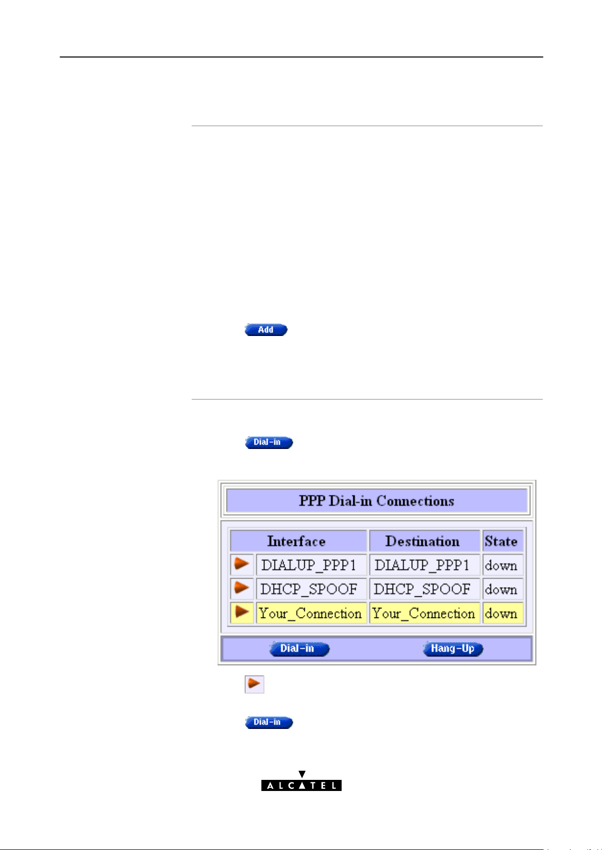
Proceed as follows (See section 21.2 for more information):
1. Click
.
on the STPro pages.
2. On the 'Dialin' page the following table is shown:
3. Click next to the PPPoE entry you want to connect with. As
a result your selection is highlighted (See example above).
4. Click
.
3EC 36231 ABAA TCZZA Ed. 01
73 / 288
Page 74

9 Configuration and Use - Routed PPPoE
5. If applicable an 'Authentication' table pops up:
Enter your username and password in the appropriate fields.
If you want the STPro to remember your credentials, check
'Save password' ().
During the session
Closing dialin PPPoE
sessions
6. Click
7. After identification and authentication the 'PPP connections'
page reappears.
While the STPro tries to open the session 'trying' will
appear in the 'State' field. Once the session is active the field
displays 'up'. From then you are online and you can start
your application or browse the Internet.
During the time the session is up, you can overview some
important connection statistics on the 'PPP' page.
See section 9.4.4 for more information.
Proceed as follows:
1. Browse to the 'Dialin' page.
2. Active PPPoE sessions are indicated via up in the 'State' field.
.
74 / 288
Click
close the session for. As a result your selection is highlighted.
3. Click
The session state of the PPPoE entry will change to down, i.e.
it becomes idle.
next to the active PPPoE entry in the list you want to
.
3EC 36231 ABAA TCZZA Ed. 01
Page 75

9 Configuration and Use - Routed PPPoE
9.3 Routed PPPoE Configuration
Introduction
Note
The 'PPP' page and
description
This section describes the use of the STPro 'PPP' page for Routed
PPPoE.
Most, if not all configurations for Routed PPPoE connections are
identical to the configuration of Routed PPPoA connections.
Therefore most configurational aspects in this section will be
referred to the configuration sections of chapter 11.
Click in the left pane of the STPro pages to pop up the
'PPP' page (See section 21.2 for more information):
3EC 36231 ABAA TCZZA Ed. 01
See section 11.3 for a description of all fields of the 'PPP
Configuration' table.
75 / 288
Page 76

9 Configuration and Use - Routed PPPoE
Adding entries
Proceed as follows:
1. Browse to the 'PPP' page.
2. If needed, click
.
3. Select the PPPoE protocol from the 'Protocol' popdown list.
4. Select the phonebook entry from the 'Address' popdown list.
You must use a ETHoA or any type" phonebook entry for
Routed PPPoE connections.
Note: In case the presented phonebook entries do not suite your desired
configuration, you must firstly create a correct phonebook entry. See
section 13.3 for more information.
5. Select the encapsulation method for the Routed PPPoE entry
from the 'Encapsulation' popdown list.
6. Optionally, enter username and password for the Routed
PPPoE entry.
Note: In case you do not enter this information it is asked each time you
open the Routed PPPoE session.
7. Optionally, enter the appropriate configurations in the
'Detailed Configuration' table.
Detailed configuration
Deleting entries
See section 9.4 for more information.
8. Click
and to finish the procedure.
Prior to using the PPPoE entry you may need to enter additional
configurations for the connection.
See section 9.4 for more information.
On the 'PPP' page, click next to the PPPoE connection you
want to delete. As a result your selection is highlighted.
Click
and .
76 / 288
3EC 36231 ABAA TCZZA Ed. 01
Page 77

9.4 Detailed Configuration
9 Configuration and Use - Routed PPPoE
Introduction
The 'Detailed
Configuration' table
Additional configuration of the Routed PPPoE entry may be needed
in the 'Detailed Configuration' table.
This section describes the various PPPoE connection configurations
the STPro offers for assuring endtoend connectivity.
On the 'PPP' page a 'Detailed Configuration' table can be found.
The contents of this table are always related to the highlighted
entry in the 'PPP Configuration' table.
The 'Detailed Configuration' table contains three or four tabs.
Three tabs, 'PPPoE', 'Routing' and 'Other' allow you to overview
or configure connection related settings for the Routed PPPoE
entry. The fourth tab 'Stats' appears only if a session is running on
the selected Routed PPPoE entry.
After configuration of these detailed Routed PPPoE entry aspects,
press
and to apply and save your changes.
Interaction with the
STPro IP router
In this section
Most of the configurations described in this section, influence the
IP router in the STPro.
See chapter 14 for more information on IP routing aspects.
Topic See
'PPPoE' Configurations 9.4.1
'Routing' Configurations 9.4.2
'Other' Configurations 9.4.3
'Stats' During a Routed PPPoE Session 9.4.4
3EC 36231 ABAA TCZZA Ed. 01
77 / 288
Page 78

9 Configuration and Use - Routed PPPoE
9.4.1 'PPPoE' Configurations
The 'PPPoE' tab
PPPoE Service and
Access Concentrator
The STPro Routed PPPoE embedded session client allows to
configure your PPPoE session for connecting for a dedicated
Service via an Access Concentrator.
If applicable, both Service name and Access Concentrator will be
provided by the SP.
For more information, contact your SP.
78 / 288
3EC 36231 ABAA TCZZA Ed. 01
Page 79

9.4.2 'Routing' Configurations
The 'Routing' tab
9 Configuration and Use - Routed PPPoE
Configurable items
The 'Routing' tab allows you to configure the IP routing aspects of
the selected Routed PPPoE entry.
Following routing aspects are configurable:
Connection sharing
This field allows you to configure which LAN members,
besides the PC that opened the Routed PPPoE session, can use
the connection.
Destination networks / Specific network
These fields allow you to configure which destination can be
reached over the particular Routed PPPoE entry.
Address translation (NA(P)T)
Checking this checkbox allows you to share the single Routed
PPPoE entry with multiple simultaneous users on your LAN.
For more information on these routing aspects, see subsection
11.4.1.
3EC 36231 ABAA TCZZA Ed. 01
79 / 288
Page 80

9 Configuration and Use - Routed PPPoE
9.4.3 'Other' Configurations
The 'Other' tab
Configurable items
The 'Other' tab allows you to configure the connection related
aspects of the selected Routed PPPoE entry.
Following connection aspects are configurable:
Mode
This field allows you to configure how the Routed PPPoE
session is opened.
Idle time limit
For 'Dialondemand' this checkbox allows you to specify the
time after which a running but unused PPPoE session is
closed.
Local IP / Remote IP
IP addresses are negotiated between the two PPP peers of the
Routed PPPoE session. The 'Local IP' and 'Remote IP' fields
influence this negotiation.
Primary DNS / Secondary DNS
These fields allow - optionally - to enter the IP address(es)
of the primary (and optionally the secondary) DNS server(s).
LCP echo
This checkbox allows to turn on/off LCP echo request/replies.
80 / 288
PAP
This checkbox allows to switch between Challenge Handshake
Authentication Protocol (CHAP) or Password Authentication
Protocol (PAP), and forced PAP only.
For more information on these aspects, see subsection 11.4.2.
3EC 36231 ABAA TCZZA Ed. 01
Page 81

9 Configuration and Use - Routed PPPoE
9.4.4 'Stats' During a Routed PPPoE Session
The 'Stats' tab
Configurable items
During a Routed PPPoE session a fourth tab 'Stats' is available:
The 'Stats' tab allows to overview some session statistics while a
session is running on the selected Routed PPPoE entry.
Following session statistics are available:
IP Address
The IP address at the local peer of the current PPP link. This
address can be dynamically assigned by the RAS or statically
configured on the 'Other' tab fields.
Bytes received / Bytes sent
The number of bytes received and sent since the Routed PPPoE
session came up.
Bytes dropped
The number of bytes dropped, i.e. discarded due to failure
since the Routed PPPoE session came up.
3EC 36231 ABAA TCZZA Ed. 01
81 / 288
Page 82

9 Configuration and Use - Routed PPPoE
82 / 288
3EC 36231 ABAA TCZZA Ed. 01
Page 83

10 Configuration and Use - Relayed PPPoA
10 Configuration and Use - Relayed PPPoA
Introduction
See also
Topics
Relayed PPPoA(*) is the packet service of your choice as it:
Provides standard Dialin PPP behavior
Supports security via identification, authentication and
encryption
Has multiprotocol support depending on the PPTP
implementation, e.g. for MS Windows: TCP/IP, IPX/SPX and
NETBEUI
Offers complete TCP/IP protocol transparency; no NA(P)T is
required
Supports concurrent access to multiple remote destinations.
(*) Relayed PPP over ATM (PPPoA) is also referred to as PPPoAtoPPTP Relaying
or PPPoA/PPTP.
Routed PPPoA packet service in chapter 11.
Topic See
3EC 36231 ABAA TCZZA Ed. 01
Preparatory Steps 10.1
Using Relayed PPPoA 10.2
Example : MS Windows 98 DialUp Networking 10.3
Relayed PPPoA Configuration 10.4
83 / 288
Page 84

10 Configuration and Use - Relayed PPPoA
10.1 Preparatory Steps
Needed information
Multiple destination
PC(s)
VPI/VCI value of the VC(s) to use on the DSL line
PPPoA (RFC2364) connection service must be supported on
this VC
Encapsulation method (VCMUX)
Remote access server must be a PPP(oA) server
Username and password for your user account.
The STPro can manage up to 12 Relayed PPPoA connections
simultaneously.
Note: Check with your SP or corporate whether multiple endtoend connectivity
is enabled.
Your PC must support PointtoPoint Protocol (PPP) and
PointtoPoint Tunnelling Protocol (PPTP).
Note: All Microsoft Windows and Mac platforms support PPP and PPTP.
TCP/IP
A PPTP DialUp application must be installed on your PC.
Note: All Microsoft Windows and Mac platforms have a PPTP DialUp
application installed per default.
Before you can establish PPTP tunnels, you must configure:
A local IP address in each PC which initiates a PPTP tunnel
A local IP address in the STPro which terminates the PPTP
tunnel(s).
See chapter 14 for more information on IP.
84 / 288
3EC 36231 ABAA TCZZA Ed. 01
Page 85

10.2 Using Relayed PPPoA
10 Configuration and Use - Relayed PPPoA
Introduction
In this section
Before you can open a PPTP tunnel towards the STPro, firstly you
must initially configure a PPTP dialup connection on your PC.
Once this PPTP dialup connection is configured you can use it to
open a Relayed PPPoA connection to the remote side of the DSL
line.
Because the configuration and use of such a connection follows
similar patterns for all popular OSs, this section will describe the
procedures in global.
In section 10.3 an example is provided how to create and use a
PPTP DialUp icon in MS Windows 98.
Topic See
Preparing the PC for PPTP Tunneling 10.2.1
Using PPTP towards the STPro 10.2.2
3EC 36231 ABAA TCZZA Ed. 01
85 / 288
Page 86

10 Configuration and Use - Relayed PPPoA
10.2.1 Preparing the PC for PPTP Tunneling
Creating a PPTP
connection icon
PPTP connection
parameters
Most, if not all OSs provide a Graphical User Interface (GUI)
guided procedure for the initial creation of a PPTP connection
icon.
The result of such creation is in most cases an icon, or entry in a
folder or a table called 'RAS', 'DialUp Networking', 'PPTP', 'Call
sessions', etc.
During the initial configuration of your PPTP connection icon, you
must provide the following parameters:
A name for the PPTP connection icon
The VPN server's IP address, or DNS hostname, i.e. the
STPro's IP address, or DNS hostname
Optionally, you can complete this entry with the following string
information:
The VC's PPPoA phonebook name - configured on your
STPro - to be used for this connection
Note: Only in case multiple PPPoA or any phonebook entries are directed
towards different destinations, you must add the appropriate phonebook
name to the dialstring. This allows the STPro to open the session to the
correct specific destination. In case all PPPoA and/or any phonebook
entries are directed towards the same destination, it is better not to add a
phonebook name to the dialstring.
86 / 288
A PPTP profile name - configured via the STPro's CLI - to
be used for this connection.
3EC 36231 ABAA TCZZA Ed. 01
Page 87

10 Configuration and Use - Relayed PPPoA
10.2.2 Using PPTP towards your STPro
PPPoA configuration
Opening a session
Per default, following PPPoA phonebook entries are available for
Relayed PPPoA connections:
RELAY_PPP1 (PPPoA on 8.48)
RELAY_PPP2 (PPPoA on 8.49)
RELAY_PPP3 (PPPoA on 8.50)
RELAY_PPP4 (PPPoA on 8.51)
DIALUP_PPP3 (PPPoA on 8.66)
In case these PPPoA phonebook entries do not meet your
requirements, you can configure a new one.
See section 13.3 for more information.
Depending on your OS, you can open a session by either double
clicking the PPTP session icon or selecting it from a RAS table and
clicking 'DialUp' or 'Connect'.
Credentials
Before you can actually browse the Internet or contact the remote
side's resources, you must supply the following credentials:
A username
An associated password.
Note: Most, if not all OSs allow the credentials to be saved.
3EC 36231 ABAA TCZZA Ed. 01
87 / 288
Page 88

10 Configuration and Use - Relayed PPPoA
10.3 Example : MS Windows 98 DialUp Networking
In this section
The following overview summarizes the necessary steps to setup a
Microsoft Windows 98 PC for the use of Relayed PPPoA:
Step Action See
1 Configure a Private IP address on your PC
2 Create a new DialUp Networking icon 10.3.1
5 Open a DialUp Session 10.3.2
6 Surf the Internet.
7 Close a DialUp Session in Use 10.3.3
88 / 288
3EC 36231 ABAA TCZZA Ed. 01
Page 89

10 Configuration and Use - Relayed PPPoA
10.3.1 Create a New DialUp Networking Icon
Procedure
Proceed as follows:
Step Action and Description
1
Doubleclick the 'My Computer' icon on your desktop.
Doubleclick the 'DialUp Networking' icon.
2
Doubleclick the 'Make New Connection' icon to activate the 'Make
3
New Connection' wizard.
If you use the DialUp Networking application for the first time, the
4
'Welcome to DialUp Networking' window appears.
In that case, click
The 'Make New Connection' window pops up:
3EC 36231 ABAA TCZZA Ed. 01
89 / 288
Page 90

10 Configuration and Use - Relayed PPPoA
Step Action and Description
In the first input field of the 'Make New Connection' window, type a
5
name, e.g. an alias for the organization you are connecting to.
Note: This name will appear below the DialUp icon at the end of
this procedure.
In the 'Select a device' popdown list of the 'Make New Connection'
6
window, you must select the 'Microsoft VPN Adapter' for PPTP
tunneling.
7
Click to pop up the VPN server window:
8
Enter the DNS hostname or IP address of the Virtual Private
Network (VPN) server.
Note: VPN server" is another word for PPTP server which is in this
case your STPro.
The default IP address for the STPro is 10.0.0.138.
Its default hostname is SpeedTouch".
Optionally, you can add the phonebook name to specify which VC is
to be used for the connection. Optionally this phonebook name can
be followed by a PPTP profile.
A window pops up confirming that you have successfully installed a
9
new DialUp connection.
Click to finish the procedure.
90 / 288
3EC 36231 ABAA TCZZA Ed. 01
Page 91

10 Configuration and Use - Relayed PPPoA
Result
Creating multiple
DialUp icons for
multiple destinations
A new icon with the name of the connection you have just created
will be added to your 'DialUp Networking' folder:
Per destination you can create a unique icon. To do so, repeat the
steps starting with step 3 of the previous procedure.
3EC 36231 ABAA TCZZA Ed. 01
91 / 288
Page 92

10 Configuration and Use - Relayed PPPoA
10.3.2 Open a DialUp Session
Procedure
Proceed as follows:
Step
Action and Description
Doubleclick the appropriate DialUp icon in the 'DialUp
1
Networking' folder or doubleclick its shortcut on your desktop.
The 'Connect To' window pops up:
2
Fill in your user name and password, according your user account at
the SP or Corporate.
Note: If you want the current DialUp connection to remember your
credentials for future use, check the 'Save Password' box (). Make
sure though that you have logged in when you boot your PC.
3
Click
The 'Connecting To Corporate' window appears shortly before being
minimized in the system tray:
Start your application now, e.g. a Web browser.
4
92 / 288
3EC 36231 ABAA TCZZA Ed. 01
Page 93

w
10 Configuration and Use - Relayed PPPoA
While you are
connected
The 'Connected To'
windo
Once the DialUp connection is established, you can find the
MSDUN icon showing two PCs connected to each other in the
system tray:
The MSDUN icon symbolizes activity on the Relayed PPPoA
connection by flashing PC(s):
A flashing Front" PC symbolizes upstream (T
) link activity
X
(from your local PC towards the STPro)
A flashing Behind" PC symbolizes downstream (R
) link
X
activity (from the STPro towards your PC).
You can check the status of the connection by doubleclicking the
MSDUN icon
in the system tray.
A 'Connected To' window will pop up, showing the status of the
connection:
3EC 36231 ABAA TCZZA Ed. 01
93 / 288
Page 94

10 Configuration and Use - Relayed PPPoA
10.3.3 Close a DialUp Session in Use
Procedure
Proceed as follows:
Step Action and Description
1
If the DialUp connection is minimized, click the MSDUN icon in
the system tray:
The 'Connected To' window pops up:
2
Click to close the session.
Result
The PPTP tunnel to the STPro will no longer exist. The Relayed
PPPoA entry on the STPro is made available again for other users.
94 / 288
3EC 36231 ABAA TCZZA Ed. 01
Page 95

10 Configuration and Use - Relayed PPPoA
10.4 Relayed PPPoA Configuration
Introduction
In this section
The 'PPTP' page
This section describes the use of the STPro 'PPTP' page.
The 'PPTP' Page
The 'Active PPTP Connections' Table
'Active PPTP Connections' Table Components
Advanced Configuration
Tunneling from behind an IP Router.
Click in the left pane of the STPro pages to pop up the
'PPTP' page (See section 21.2 for more information):
3EC 36231 ABAA TCZZA Ed. 01
95 / 288
Page 96
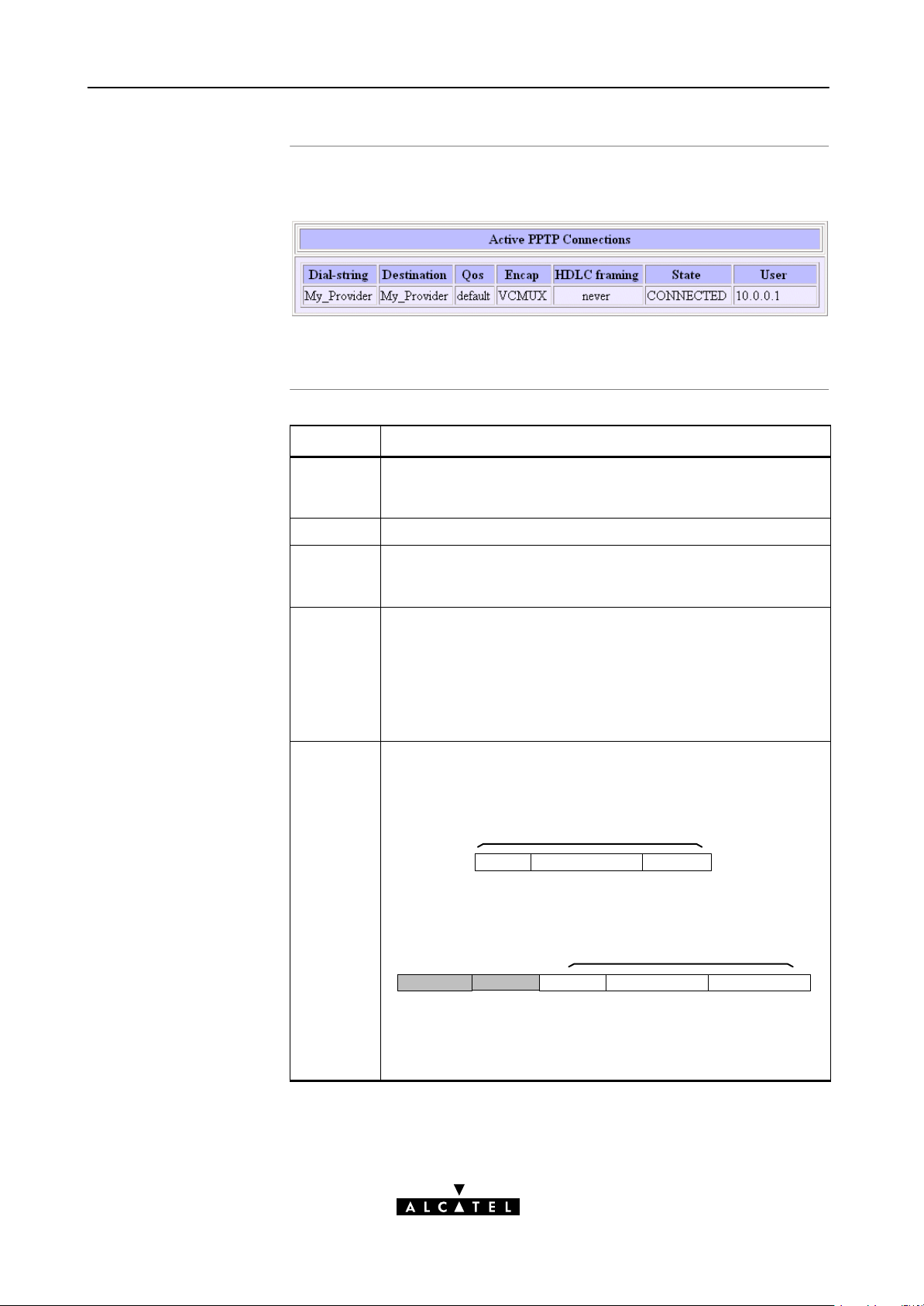
10 Configuration and Use - Relayed PPPoA
The 'Active PPTP
Connections' table
'Active PPTP
Connections' table
components
The following figure shows the 'Active PPTP Connections' table:
In the example one active Relayed PPPoA connection is up.
Field Description
Dialstring In your DialUp application you are able to specify which PPPoA
entry (and PPTP profile) is to be used by adding the appropriate
dialstring. This dialstring is indicated here, if applied.
Destination Indicates the PPPoA phonebook entry name in use.
Qos Indicates the Quality of Service (QoS) applicable for the Relayed
PPPoA connection. In most cases the Qos column will indicate
default. Via the CLI you can configure a specific QoS profile(*).
Encap Indicates the applied encapsulation method for PPP frames in the
VC.
HDLC
Framing
The STPro supports both the VCMUX method (default) and the
LLC/NLPID method.
The encapsulation method for a Relayed PPPoA connection can
be configured via the CLI.
The PPP frames arriving via a PPTP tunnel, and the PPP frames
encapsulated on ATM connections, differ in format.
The PPP format on AAL5 follows RFC 1661 PointtoPoint
Protocol (PPP)":
PPP Frame
P_ID Information Padding
Whereas the PPP format within a tunnel follows PointtoPoint
Tunneling Protocol (PPTP)":
PPP Frame
Address Control P_ID Information Padding
(FF) (03)
The latter format has two additional bytes in front of the frame
(FF03) inherited from another encapsulation i.e. RFC 1662 PPP
in HDLClike framing".
96 / 288
3EC 36231 ABAA TCZZA Ed. 01
Page 97

Field Description
10 Configuration and Use - Relayed PPPoA
HDLC
Framing
(continued)
In order to cope with these PPP frame differences, the STPro
adapts to the different formats on a 'per connection' base.
Additionally, the STPro offers the following PPP/AAL5 format
configuration options via the CLI if interoperability problems
should arise:
Value Description
Never
Always
Keep
Note: This configuration possibility applies only to the upstream
direction ! In the downstream direction, the STPro will always
make sure that FF03 is in front of the frame prior to put it in a
PPTP tunnel.
The STPro will make sure that FF03
will never be found in front of a PPP
frame encapsulated on a AAL5/ATM
connection, independent of the actual
format of the PPP frame in the tunnel.
This setting is default, and follows
RFC2364.
The STPro will make sure that FF03 is
always in front of a PPP frame
encapsulated on an AAL5/ATM
connection. Although not supported by
RFC2364, some equipment may rely
on this format.
The STPro will not change the PPP
frame arriving via a tunnel.
Advanced
configuration
State
User
Indicates that the Relayed PPPoA connection is up
("CONNECTED").
As soon as a PC initiates a PPTP tunnel towards the STPro, its IP
address is indicated in the 'User' field.
You can instruct the STPro to use a specific PPPoA phonebook
entry by adding its phonebook name next to the STPro's IP
address or DNS hostname in the DialUp application on your PC.
The phonebook name string can optionally be followed by a PPTP
profile name, configured via the CLI. This PPTP profile allows you
to specify:
Encapsulation method (default = VCMUX)
HDLC framing (default = never)
QoS (default = default).
3EC 36231 ABAA TCZZA Ed. 01
97 / 288
Page 98

y
10 Configuration and Use - Relayed PPPoA
Tunneling from behind
an IP router
STPro
The STPro allows local tunneling from behind an IP router:
172.16.0.2
IP Router Local PPTP tunnels
Ethernet LAN
172.16.0.3
10.0.0.138 10.0.0.1
IP Network 10
172.16.0.1
IP Network 172.16
This requires settings in both STPro and PCs.
You must add a default route for the STPro via the 'Routing' page
(See section 14.5 for more information).
In the example of the figure above the route to be added has the
following parameters:
Destination: 0.0.0.0/0
Source: Any
Gateway: 10.0.0.1
PCs
Verify connectivit
For each PC, you must add a route to its internal routing table.
This route must point to the STPro.
In the example of the figure above the route to be added to each
PC's routing table has the following parameters:
Destination: 10.0.0.138
Gateway: 172.16.0.1
You can verify connectivity from behind the IP router by applying a
ping to the STPro.
98 / 288
3EC 36231 ABAA TCZZA Ed. 01
Page 99

11 Configuration and Use - Routed PPPoA
11 Configuration and Use - Routed PPPoA
Introduction
In this chapter
Routed PPPoA(*) is the packet service of your choice as it:
Has an authenticated session concept: it supports
identification, authentication and autoconfiguration
Requires no session client on the PC(s), avoiding special
installation procedures
Allows multiple users to share a single IP address if NA(P)T is
enabled
Allows your local network to be shielded from the Internet via
STPro's programmable Firewall.
(*) Routed PPPoA is also referred to as PPP & IP Routing.
Topic See
Preparatory Steps 11.1
Using Routed PPPoA 11.2
Routed PPPoA Configuration 11.3
3EC 36231 ABAA TCZZA Ed. 01
Detailed Configuration 11.4
99 / 288
Page 100

11 Configuration and Use - Routed PPPoA
11.1 Preparatory Steps
Needed information
Multiple destinations
PC(s)
VPI/VCI value of the VC(s) to use on the DSL line
PPPoA (RFC2364) connection service must be supported on
this VC
Encapsulation method (VCMUX)
Remote access server must be a PPP(oA) server
Username and password for your user account.
The STPro can manage up to 12 Routed PPPoA connections
simultaneously.
Note: Check with your SP or corporate whether multiple endtoend connectivity
is enabled.
In order to use the Routed PPPoA mode of the STPro, the OS on
your PC(s) must support TCP/IP.
See chapter 14 for more information on IP.
100 / 288
3EC 36231 ABAA TCZZA Ed. 01
 Loading...