

Page 1

Alcatel™ DSL Router Family
Command Line Interface Guide
P/N 3EC 16963 AAAA-TCZZA
Page 2

October 1999
Copyright
Alcatel provides this publication “as is” without warranty of any kind, either expressed or implied, including, but
not limited to, the implied warranties of merchantability or fitness for a particul ar purpos e.
All rights reserved. No part of this book may be reproduced in any form or by any means without written
permission from Alcatel .
Changes are periodically made to the information in this book. They will be incorporated in subs equent editions.
Alcatel may make improvements and/or changes in the product described in this publication at any time.
© Copyright 1996-1999 Alcatel
Trademarks
Alcatel is a trademark of Alcatel.
All other trademarks and registered trademarks mentioned in this manual are the sole property of their respective
companies.
2 Alcatel™ DSL Router Family Command Line Interface
Page 3

Preface
About This Guide
Command Line Interface
The
for the family of DSL routers. It provides the steps and information needed to configure the router software and
troubleshoot problems using the Command Line Interface. Configuration of network connections, bridging,
routing, and security features are essentially the same for all DSL routers, unless otherwise noted. The guide also
provides detailed information about the system’s bridging, routing, addressing, and security oper ations.
This guide is intended for small and home office users, remote office users, and other networking professionals
who are installing and maintaining bridged and routed networks.
How This Guide is Organized
This guide is intended to help you configure and manage the router using the Command Line Interface. The guide
assumes that you have read the information about the router and installed the hardware using the
Start Guide
. The guide is divided into eight parts:
guide contains information on the syntax and use of the Command Line Interface
Internet Quick
Introduction.
Advanced Topics.
operations, PAP/CHAP security negotiation, bandwidth management, protocol conformance, and the file system.
Planning for Router Configurat ion.
Interface including worksheets for collecting required information.
Configuring Router Software.
Configuring Special Features.
NAT, Management Security, Software Options Keys, Encryption, IP Filtering, and L2TP Tunneling.
Command Line Interface Reference.
is entered.
Managing the Router.
how to upgrade the system software, boot code, backup and restore configuration files, FLASH memory recovery
procedures, and batch file command execution.
Troubleshooting.
Describes the features of the Command Line Interface.
Contains additional information on topics such as interoperability, routing and bridging
Provides information unique to configuration using the Command Line
Describes how to configure the router using the Command Line Interface.
Describes how to configure features such as Bridging Filtering, RI P, DH CP,
Describes the syntax of each command and the results when the comman d
Describes SNMP management capabilities, TFTP client and s erver , TE LNET s upport and
Describes diagnostic tools used for identifying and correcting hardware and software problems.
Page 4

References
User Guide.
installation and software configuration using the Windows-based Configuration Manager.
Quick Start Guide.
Contains an overview of the router’s software and hardware features and details on hardware
Describes the configuration process involved in setting up a specific router model.
Typographic Conventions
The following conventions are used in this guide:
Item Type Face Examples
Book titles, command
reference parameters,
reference to a specific
section/chapter in this
guide, emphasis in text.
Keywords in command
reference instructions
Examples showing you what
to type and what is
displayed on the terminal.
Italics Refer to Chapter 1.
Features
system name <
Bold
Mono-spaced font
save
remote listIpRoute hq
Advanced
name>
File names Upper case Copy file CFGMGR.EXE
4 Preface
Page 5

Table of Contents
Preface 3
About This Guide 3
How This Guide is Organized 3
References 4
Typographic Conventions 4
Table of Contents 5
Introduction 9
Chapter 1. Advanced Topics 11
Interoperability 11
Routing 11
Bridging 12
Bridging and Routing Operation 12
Bridging and Routing Configuration Settings 13
Point-To-Point Pr otocol (PPP ) 14
PAP/CHAP Security Authentication 14
General Security Authentication 15
Security Configuration Settings 16
Authentication Process 16
Protocol Conformance 17
Protocol Standards 17
IP Routing 17
IPX Routing 17
Encapsulation Options 17
PPP 18
PPPLLC 18
RFC 1483 or RFC 1490 18
MAC Encapsulated Routing: RFC 1483MER (ATM) or RFC 1490MER (Frame Relay) 19
FRF8 19
rawIP 19
System Files 20
Bridge Filtering 20
Unique System Passwords 22
Chapter 2. Planning for Router Configuration 23
Important Terminology 23
Essential Configuration Information 24
PPP Link Protocol (over AT M or Frame Relay) 25
RFC 1483/RFC 1490 Link Protocols 30
MAC Encapsulated Routing: RFC 1483MER/RFC 1490MER Link Protocols 35
FRF8 Link Protocol 37
Dual-Ethernet Router Configuration 39
Chapter 3. Configuring Router Software 40
Configuration Tables 41
Configuring PPP with IP Routing 42
Configuring PPP with IPX Routing 43
Configuring PPP with Bridging 44
Configuring RFC 1483 / RFC 1490 with IP Routing 45
Configuring RFC 1483 / RFC 1490 with IPX Routing 46
Configuring RFC 1483 / RFC 1490 with Bridging 47
Table of Contents 5
Page 6

Configuring MAC Encapsulated Routing: RFC 1483MER / RFC 1490MER with IP Routing 48
Configuring FRF8 with IP Rout ing 49
Configuring Mixed Network Protocols 50
Configuring a Dual-Ethernet Router for IP Routing 51
Verify the Router Configuration 52
Test IP Routing 52
Test Bridging to a Remote Destination 52
Test IPX Routing 53
Sample Configurations 54
Sample Configuration 1: PPP with IP and IPX 54
Sample Confi guration 2: RFC 1483 with IP and Bridging 62
Sample Configuration 3: Configuring a Dual-Ethernet Router for IP Routing 68
Chapter 4. Configuring Special Features 69
Bridge Filtering and IP Firewall 69
General Information 69
Configure Bridge Filtering 69
Enable/Disable Internet Firewall Filtering 70
IP (RIP) Protocol Controls 71
Dynamic Host Configuration Protocol (DHCP) 72
General Information 72
Manipulating Subnetwor ks and Explici t Clien t Leases 73
Setting Option Values 75
BootP 77
Defining Option Types 79
Configuring BootP/DHCP Relays 80
Other Information 80
Network Address Translation (NAT) 80
General NAT Rules 80
Masquerading 81
Classic NAT 84
Client Configuration 85
Management Security 87
Disable Telnet and SNMP 87
Restore Telnet and SNMP 87
Validation of Telnet and SNMP Clients 87
Restrict Remote Access 88
Changing the SNMP Community Name 88
Disable WAN Management 88
System Log 89
Software Option Ke ys 89
Encryption 89
PPP DES (RFC 1969) Encryption 90
Diffie-Hellman Encryption 92
IP Filtering 93
Filters and Interfaces 93
Configuring Filters with Network Address Translation Enabled 94
Filter Actions 95
IP Filter Commands 95
Special Notes 95
L2TP Tunneling — Virtual Dial-Up 96
Introduction 96
L2TP Concepts 96
Configuration 99
6 Table of Contents
Page 7

Sample Configurations 101
Chapter 5. Command Line Interface Reference 109
Command Line Interface Conventions 109
Command Input 109
Command Output 109
Command Or ganization 109
? or HELP 110
System-Level Commands 111
Frame Statistics 113
Router Configuration Com mands 120
Target Router System Configuration Commands (SYSTEM) 121
Target Router Ethernet LAN Bridging and Routing (ETH) 134
Remote Router Access Configuration (REMOTE) 143
Asymmetric Digital Subscriber Line Commands (ADSL) 166
Asynchronous Transfer Mode Commands (ATM) 168
DMT Command 171
Dual-Ethernet Router Commands (ETH) 172
High-Speed Digital Subscriber Line Commands (HDSL) 176
ISDN Digital Subscriber Line (IDSL) 179
Symmetric Digital Subscriber Line Commands (SDSL) 181
Dynamic Host Configuration Protocol Commands (DHCP) 185
L2TP — Virtual Dial-Up Configu ration (L2TP) 196
Bridge Filtering Commands (FILTER BR) 204
Save Configuration Commands (SAVE) 206
Erase Configuration Commands (ERASE) 208
File System Commands 210
Chapter 6. Managing the Router 215
Simple Network Management Protocol (SNMP) 215
Telnet Remote Access 216
Client TFTP Facility 216
TFTP Server 216
BootP Server 217
Boot Code 217
Manual Boot Menu 217
Identifying Fatal Boot Failures 221
Software Kernel Upgrades 221
Booting an d Upgrading from the LAN 221
Upgrading from the WAN Line 223
Backup and Restore Configuration Files 224
Backup Configuration Files (Recommended Procedure) 224
Restore Configuration Files 224
FLASH Memory Recovery Procedures 225
Recovering Kernels for Routers with Configuration Switches 225
Recovering Kernels for Routers with a Reset Button 226
Recovering Passwords and IP Addresses 227
Routers with Configuration Switches 227
Routers with a Reset Button 2 28
Batch File Command Execution 228
Chapter 7. Troubleshooting 231
Diagnostic Tools 231
Using LEDs 231
Table of Contents 7
Page 8

History Log 232
Ping Command 233
Investigating Hardware Installation Problems 234
Check the LEDs to Solve Common Hardware Problems 234
Problems with the Terminal Window Display 234
Problems with the Factory Configuration 234
Investigating Software Configuration Problems 235
Problems Connecting to the Router 235
Problems with the Login Password 235
Problems Accessing the Remote Network 236
Problems Accessing the Router via Telnet 238
Problems Downloading Software 238
System Messages 238
Time-Stamped Messages 239
History Log 241
How to Obtain Technical Support 241
Appendix A. Network Information Worksheets 243
Configuring PPP with IP Routing 244
Configuring PPP with IPX Routing 245
Configuring PPP with Bridging 246
Configuring RFC 1483 / RFC 1490 with IP Routing 247
Configuring RFC 1483 / RFC 1490 with IPX Routing 248
Configuring RFC 1483 / RFC 1490 with Bridging 249
Configuring RFC 1483MER / RFC 1490MER with IP Routing 250
Configuring FRF8 with IP Rout ing 251
Configuring a Dual-Ethernet Router for IP Routing 252
Appendix B. Configuring IPX Routing 253
IPX Routing Concepts 253
Configure IPX Routing 253
Step 1: Collect Your Network Information for the Target (Local) Router 254
Step 2: Review your Settings 255
Appendix C. Access the
Command Line Interface 257
Connect the PC to the Console Port of the Router 257
Access the Command Line Interface 257
Terminal Window under Configuration Manager 257
Terminal Session under Windows (HyperTerminal) 258
Terminal Session for a Non-Windows Platform (Macintosh or UNIX) 258
Telnet Session 258
Index 259
8 Table of Contents
Page 9

Introduction
This guide provides steps and information needed to con figur e the DSL or Dual-Ethernet router software using the
Command Line Interface
The Command Line Interface covers the following basic configuration topics:
• Set names, passwords, PVC numbers, and link and network parameters
• Configure specific details within a protocol, such as IP or IPX addresses and IP protocol controls
• Activate bridging and routing protocols
• Enable the Internet firewall filter with IP routing
The Command Line Interface also provides the following advanced features:
• Manage the router’s file system
• Set bridging filters
• Configure the type of DSL technology specific to your router (e.g., ADSL, SDSL)
• Configure the Dual-Ethernet router
• Issue online status commands
1
.
• Monitor error messages
• Set RIP options
• Configure DHCP
• Configure NAT
• Configure Telnet/SNMP security
• Configure host mapping
• Configure IP multicast
• Create and execute script files
• Configure encryption
• Configure IP filtering
• Configure L2TP tunneling
• Enable software options keys
1. The Microsoft® Windows™-based
to-use, point-and-click GUI interface) provides another way to configure the router’s software. Please refer to
Access the Command Line Interface
Start as your primary configuration tool.
Configuration Manager or Quick Start
section in this guide if you intend to use Configuration Manager or Quick
program (featuring an easy-
Page 10

10 Introduction
Page 11

Chapter 1. Advanced Topics
This chapter provides information on advanced topics useful to network administrators.
Interoperability
The router uses industry-wide standards to ensure compatibility with routers and equipment from other vendors.
To interoperate, the router supports standard protocols on the physical level, data link level for frame type or
encapsulation method, and network level. For two systems to communicate directly, they must use the same
protocol at each level. Most protocols do not support negotiable options, except for PPP.
The physical protocol level includes hardware and electrical signaling characteristics. This support is provided by
the router Ethernet and modem hardware interfaces.
The data-link protocol level defines the transmission of data packets between two systems over the LAN or WAN
physical link.
The frame type or encapsulation method defines a way to run multiple network-level protocols over a single LAN
or WAN link. The router supports the following WAN encapsulations:
• PPP (VC multiplexing)
• PPP (LLC multiplexing)
• RFC 1483 (for ATM)
• RFC 1483 with MAC encapsulated routing (for ATM)
• FRF8 (for ATM)
• RFC 1490 (for Frame Relay)
• RFC 1490 with MAC encapsulated routing (for Frame Relay)
Routing
The network protocol provides a way to route user data from source to destination over different LAN and WAN
links. Routing relies on routing address tables to determine the best path for each packet to take.
The routing tables can be seeded; i.e., addresses for remote destinations are placed in the table along with path
details and the associated costs (path latency).
The routing tables are also built dynamically; i.e., the location of remote stations, hosts, and networks are updated
from broadcast packet information.
Routing helps to increase network capacity by localizing traffic on LAN segments. It also provides security by
isolating traffic on segmented LANs. Routing extends the reach of networks beyond the limits of each LAN
segment.
Numerous network protocols have evolved, and within each protocol are associated protocols for routing, error
handling, network management, etc. The following chart displays the networking and associated protocols
supported by the router.
Chapter 1. Advanced Topics 11
Page 12

Network Protocol Associated Protocols Description
Internet Protocol
(IP)
Internet Packet
Exchange (IPX)
a Used only during a networ k boot
b IPX-RIP is a different protocol from IP-RIP and it includes time delays
Most of the router’s operation on each protocol level is transparent to the user. Some functions are influenced by
configuration parameters, and these are described in greater detail in the following sections.
Routing Information Protocol (RIP) Maintains a map of the network
Address-Resolution Protocol (ARP) Maps IP addresses to datalink
addresses
Reverse Address Resolution Protocol (RARP)
Internetwork Control Message Protocol
(ICMP)
Simple Network Management Protocol
(SNMP)
Routing Information Protocol (RIP)
Service Advertising Protocol (SAP) Distributes information about service
a
b
Maps data-link addresses to IP
addresses
Diagnostic and error reporting/
recovery
Network management
Maintains a map of the network
names and addresses
Bridging
Bridging connects two or more LANs so that all devices share the same logical LAN segment and network
number. The MAC layer header contains source and destination addresses used to transfer frames.
An address table is dynamically built and updated with the location of devices when the frames are received.
Transparent bridging allows locally connected devices to send frames to all devices as if they were local.
Bridging allows frames to be sent to all destinations regardless of the network protocols used. It allows protocols
that cannot be routed (such as NETBIOS) to be forwarded and allows optimizing internetwork capacity by
localizing traffic on LAN segments. A bridge extends the physical reach of networks beyond the limits of each
LAN segment. Bridging can increase network security with filtering.
The router bridging support includes the IEEE 802.1D standard for LAN-to-LAN bridging and the Spanning Tree
Protocol for interoperability with other vendors’ bridge/routers. Bridging is provided over PPP as well as adjacent
LAN ports. Most of the r outer’s bridging operation is t rans parent . S ome f unct ion s are influenced by configuration
parameters, which are described in greater detail in the following sections.
Bridging and Routing Operation
The router can operate as a bridge, a router, or as both (sometimes called a brouter).
12 Chapter 1. Advanced Topics
Page 13

• The router will operate as a router for network protocols that are enabled for routing (IP or IPX).
• The router will operate as a bridge for protocols that are not supported for routing.
• Routing takes precedence over bridging; i.e., when routing is active, the router uses the packet’s protocol
address information to route the packet.
• If the protocol is not supported, the router will use the MAC address information to forward the packet.
Operation of the router is influenced by routing and bridging controls and filters set during router configuration as
well as automatic spoofing and filtering performed by the router. For example, general IP or IPX routing, and
routing or bridging from specific remote routers are controls set during the configuration process.
Spoofing and filtering, which minimize the number of packets that flow across the WAN, are performed
automatically by the router. For example, RIP routing packets and certain NetBEUI packets are spoofed even if
only bridg ing is enabled.
Bridging and Routing Configuration Settings
The router can be configured to perform general routing and bridging while allowing you to set specific controls.
One remote router is designated as the outbound default bridging destination. All outbound bridging traffic with
an unknown destination is sent to the default bridging destination. Bridging from specific remote routers can be
controlled by enabling or disabling bridging from individual remote routers.
Routing is performed to all remote routers entered into the remote router database. All routing can be enabled or
disabled with a system-wide control.
The following charts describe the operational characteristics of the router, based on configuration settings.
IP/IPX Routing On Bridging to/from Remote Router Off
Data packets carried IP (TCP, UDP), IPX
Operational
characteristics
Typical usage When only IP/IPX traffic is to be routed and all other traffic is to be
Basic IP, IPX connectivity
ignored. For IP, used for Internet access.
Note:
This is the most easily controlled configuration.
Chapter 1. Advanced Topics 13
Page 14

IP/IPX Routing On Bridging to/from Remote Router On
Data packets carried IP/IPX routed; all other packets bridged.
Operational
characteristics
T ypical usage When only IP/IPX traffic is to be routed b ut some non-r outed proto col is
IP/IPX routing and allows other protocols, such as NetBEUI (that can’t
be routed) , to be bridged.
required. Used for client/server configurations.
IP/IPX Routing Off Bridging to/from Remote Router On
Data packets carried All packets bridged.
Operational
characteristics
Typical usage Peer-to-peer bridging and when the remote end supports only bridging.
Allows protocols, such as NetBEUI (that can’t be routed) to be bridged.
Point-To-Point Protocol (PPP)
PPP is an industry standard WAN protocol for transporting multi-protocol datagrams over point-to-point
connections. PPP defines a set of protocols, such as security and network protocols, that can be negotiated over
the connection. PPP includes the following protocols:
• Link Control Protocol (LCP) to negotiate PPP; i.e., establish, configure and test the datalink connection.
• Network Control Protocols (NCPs), such as:
TCP/IP routing Internet Protocol Control Protocol (IPCP)
IPX routing Control Protocol (IPXCP)
Bridge Control Protocol (BN CP)
• Security Protocols including PAP and CHAP
A more detailed description of the router’s implementation of some of these protocols appears the following
section. A list of PPP protocol conformance is included later in this section.
PAP/CHAP Security Authentication
Password Authentication Protocol (PAP) and Challenge Handshake Authentication Protocol (CHAP) under PPP
are supported by the router. However, security authentication may or may not be needed depending on the
requirements of the remote end.
The nature of the connection in a DSL environment (traffic occurs on a dedicated line/virtual circuit) does not
require authentication unless that is specifically required by the remote end, the ISP, or the NSP. When
authentication is not required, security can be disabled with the command
remote disauthen
.
14 Chapter 1. Advanced Topics
Page 15
General Security Authentication
Security authentication may be required by the remote end. The following information describes how
authentication occurs.
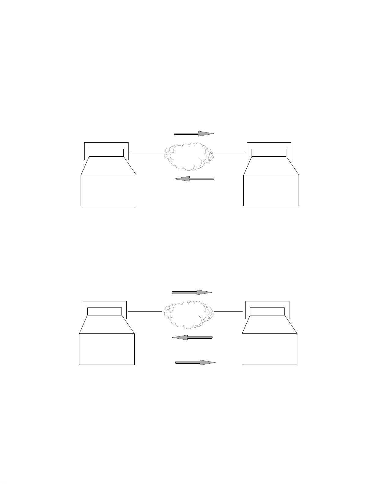
PAP provides verification of passwords between routers using a two-way handshake. One router (peer) sends the
system name and password to the other router. Then the other router (known as the authenticator) checks the
peer’s password against the configured remote router’s password and returns acknowledgment.
PAP Authentication
New York
System Name=New York
System Password=xyz
Remote Router Database
Remote=Chicago
Password=abc
1
...New York & xyz.......
2
.....Accepted/Rejected.......
Chicago
System Name=Chicago
System Password=abc
Remote Router Database
Remote=New York
Password=xyz
CHAP is more secure than PAP because unencrypted passwords are not sent across the network. CHAP uses a
three-way handshake. One router (known as the authenticator) challenges the other router (known as the peer) by
generating a random number and sending it along with the system name. The peer then applies a one-way hash
algorithm to the random number and returns this encrypted information along with the system name.
The authenticator then runs the same algorithm and compares the result with the expected value. This authentication method depends up on a password or secret known only to both ends.
CHAP Authentication
New York
CHALLENGE
...New York & random number.......
1
Chicago
Hashes random
number and
secret ‘abc’
System Name=New York
System Password=xyz
Remote Router Database
Remote=Chicago
Password=abc
Performs same
hash with number
and secret ‘abc’
and compares
results
.....Chicago & encrypted secret.......
.....Accepted/Rejected.......
2
3
System Name=Chicago
System Password=abc
Remote Router Database
Remote=New York
Password=xyz
Chapter 1. Advanced Topics 15
Page 16

Security Configuration Settings
The router has one default system password used to access any remote router. This “system authentication
password” is utilized by remote sites to authenticate the local site. The router also allows you to assign a unique
“system override password” used only when you are connecting to a specific remote router for authentication by
that remote site. Each remote router entered in the remote router database has a password used when the remote
site attempts to gain access to the local router. This “remote authentication password” is utilized by the router to
authenticate the remote site.
Each remote router entered in the remote router database also has a minimum s ecurity level, k no wn as the “remote
authentication protocol,” that must be negotiated before the remote router gains access to the local router. In
addition, a system-wide control, “system authentication protocol,” is available for overriding the minimum
security level in the entire remote router database.
Authentication Process
The authentication process occurs regardless of whether a remote router connects to the local router or vice versa,
and even if the remote end does not request authentication. It is a
authenticate the other using the protocol of its choice (provided the other end supports it).
During link negotiation (LCP), each side of the link negotiates which protocol to use for authentication during the
connection. If both the system and the remote router have PAP authentication, then they negotiate PAP
authentication.
bi-directional process
, where each end can
Otherwise, the router
the remote end does not accept either PAP or CHAP, the link is dropped; i.e., the router will not communicate
without a minimum security level. On the other hand, the router will accept any authentication scheme required by
the remote node, including no authentication at all.
During the authentication phase, each side of the link can request authentication using the method they negotiated
during LCP.
For CHAP, the router issues a CHAP challenge request to the remote side. The challenge includes the system
name and random number. The remote end, using a hash algorithm associated with CHAP, transforms the name
and number into a response value. When the remote end returns the challenge response, the router can validate the
response challenge value using the entry in the remote router database. If the response is invalid, the call is
disconnected. If the other end negotiated CHAP, the remote end can, similarly, request authentication from the
local router. The router uses its system name and password to respond to CHAP challenge.
For PAP, when a PAP login request is received from the remote end, the router checks the remote router PAP
security using the remote router database. If the remote router is not in the remote router database or the remote
router password is invalid, the call is disconnected. If the remote router and password are valid, the local router
acknowledges the PAP login request.
If PAP was negotiated by the remote end for the remote-side authentication, the router will issue PAP login
requests
router, or if the remote end returned a successful CHAP challenge response. For security reasons, the router will
never
If PAP was negotiated by the remote end for the local side of the authentication process and the minimum security
level is CHAP, as configured in the remote router database, the link will be dropped for a security violation.
only
if it knows the identity of the remote end. The identity is known if the call was initiated from th e
identify itself using PAP without first knowing the identity of the remote router.
always
requests CHAP authentication first; if CHAP is refused, PAP will be negotiated. If
16 Chapter 1. Advanced Topics
Page 17

Protocol Conformance
Protocol Standards
The router conforms to RFCs designed to address performance, authentication, and multi-protocol encapsulation.
The following RFCs are supported:
• RFC 1058 Routing Informat ion Protocol (RIP)
• RFC 1144 Compressing TCP/IP headers (Van Jacobson)
• RFC 1220 Bridging Control Protocol (BNCP)
• RFC 1332 IP Control Protocol (IPCP)
• RFC 1334 Password Authentication Protocol and Challenge Handshake Authentication Protocol (PAP/
CHAP)
• RFC 1483 Multiprotocol Encapsulation over ATM Adaptation Layer 5
• RFC 1490 Multiprotocol Interconnect over Frame Relay
• RFC 1552 Novell IPX Control Protocol (IPXCP)
• RFC 1577 Classical IP and ARP over ATM
• RFC 1661 Point-to-P oi nt Protocol (PPP)
• RFC 1723 RIP Version 2
• RFC 1962 PPP Compression Control Protocol (CCP)
• RFC 1973 PPP in Frame Relay
• RFC 1974 Stac LZS compression protocol
• RFC 1990 Multi-Link Prot ocol (MLP)
• RFC 2131 and 2132 Dynamic Host Configuration Protocol (DHCP)
IP Routing
IP routing support, in conformance with RFC 791, provides the ability to process TCP/IP frames at the network
layer for routing. IP routing support includes the Routing Interface Protocol (RIP), in conformance with RFC
1058 (RIP v.1) and RFC 1723 (RIP v.2).
IPX Routing
IPX routing conforms to the Novell® NetWare™ IPX Router Development Guide, Version 1.10.
Encapsulation Options
This section describes in technical terms the format of each packet associated with a particular encapsulation
option supported by th e router.
The encapsulation type for each remote entry is defined using the
remote setProtocol
command.
Chapter 1. Advanced Topics 17
Page 18

PPP
Each packet begins with a one- or two-byte protocol ID. Typical IDs are:
0xc021—LCP
0x8021—IPCP
0x0021—IP
0x002d— Van Jacobson compressed TCP/IP
0x002f—Van Jacobson uncompressed TCP/IP
0x8031—Bridge NCP
0x0031—Bridge Frame
The command for this encapsulation option is:
Note:
With PPP over ATM, the address and control fields (i.e., FF03) are never present; this also is the case for
LCP packets.
remote setProtocol PPP
remoteName
<
>
PPPLLC
This protocol (LLC-multiplexed) allows PPP traffic to be carried simultaneously with other traffic on a single
virtual circuit (as opposed to the PPP method of encapsulation—VC multiplexin g—which dedicates a virtual
circuit to PPP traffic only).
Each PPP packet is prepended with the sequence 0xFEFE03CF. Thus, an LLC packet has the format:
0xFEFE03CF 0xC021.
The command for this encapsulation option is:
remote setProtocol PPPLLC
remoteName
<
>
RFC 1483 or RFC 1490
Bridging
User data packets are prepended by the sequence 0xAAAA0300 0x80c20007 0x0000 followed by the
Ethernet frame containing the packet.
802.1D Spanning Tree packets are prepended with the header 0xAAAA0300 0x80C2000E.
Routing
IP packets are prepended with the header 0xAAAA0300 0x00000800.
IPX packets are prepended with the header 0xAAAA0300 0x00008137.
The commands for this encapsulation option are:
remote setProtocol RFC1483
remote setProtocol FR
18 Chapter 1. Advanced Topics
<
remoteName
<
remoteName
> (for ATM)
> (for Frame Relay - RFC 1490)
Page 19

MAC Encapsulated Routing: RFC 1483MER (ATM) or RFC 1490MER (Frame Relay)
MER encapsulation allows IP packets to be carried as bridged frames, but does not prevent bridged frames from
being sent as well, in their normal encapsulation format: RFC 1483 (ATM) or RFC 1490 (Frame Relay).
If IP routing is enabled, then IP packets are prepended with the sequence 0xAAAA0300 0x80c20007 0x0000 and
sent as bridged frames. If IP routing is not enabled, then the packets appear as bridged frames.
The commands for this encapsulation option are:
remote setProtocol RFC1483MER
remote setProtocol MER
(for Frame Relay)
remoteName
<
> (for ATM)
FRF8
IP packets have prepended to them the following sequence: 0x03CC.
The command for this encapsulation option is:
Note:
This protocol allows sending ATM over Frame Relay.
remote setprotocol FRF8
remoteName
<
>
rawIP
IP packets do not have any protocol headers prepended to them; they appear as IP packets on the wire. Only IP
packets can be transported since there is no possible method to distinguish other types of packets (bridged frames
or IPX).
The command for this encapsulation option is:
remote setProtocol rawIP
remoteName
<
>
Chapter 1. Advanced Topics 19
Page 20

System Files
The router’s file system is a DOS-compatible file system, whose contents are as follows: :
SYSTEM.CNF:
DOD Remote Router Database
SYS System Settings: name, message, authentication method, and passwords
ETH Ethernet LAN configuration settings
DHCP.DAT:
FILTER.DAT:
KERNEL.F2K:
ETH.DEF:
ASIC.AIC:
ATM.DAT:
I2TP Tunnening Database
ATOM.DAT
SDSL.DAT
DMT.DAT
IPSEC.DAT
These are configuration files containing:
DHCP files.
Bridge filters.
Router system software (KERNEL.F P 1 for IDSL routers).
File used by the manufacturer to set a default Ethernet configuration.
Firmware for the xDSL modem or ATM interface.
ATM configuration file.
IKE.DAT
AUTOEXEC.BAT - Autoexec file of commands to run on next reboot.
AUTOEXEC.OLD - Autoexec file that has run already
Note:
Users should not delete any of these files, unless advised by Tech Support.
Any file contained within the system may be retrieved or replaced using the TFTP protocol. Specifically,
configuration files and the operating system upgrades can be updated. Only one copy for the router software is
allowed in the router’s FLASH memory.
Refer to
copying configuration files, and restoring router software to FLASH memory.
Chapter 6. Managing the Router on page 215
for details on software upgrades, booting router software,
Bridge Filtering
You can control the flow of packets across the router using bridge filtering. Bridge filtering lets you “deny”or
“allow” packets to cross the network based on position and hexadecimal content within the packet. This featu re
lets you restrict or forward messages with a specified address, protocol, or data content. Common uses are to
prevent access to remote networks, control unauthorized access to the local network, and limit unnecessary traffic.
20 Chapter 1. Advanced Topics
Page 21

For example, it might be necessary to restrict remote access for specific users on the local network. In this case,
bridging filters are defined using the local MAC address for each user to be restricted. Each bridging filter is
specified as a “deny” filter based on the MAC address and position of the address within the packet. Deny
filtering mode is then enabled to initiate bridge filtering. No packet with one of the MAC addresses can be bridged
across the router until the deny filtering mode is disabled.
Similarly, protocol filtering can be used to prevent a specific protocol from being bridged. In this case, the
protocol ID field in a packet is used to deny or allow a packet. You can also restrict, for example, the bridging of
specific broadcast packets.
Chapter 1. Advanced Topics 21
Page 22

Unique System Passwords
As described in
override password for a remote router with the command
password” is used instead of the general system password
allows you to set a unique CHAP or PAP authentication password for authentication of the local site by the remote
only
site
A common use is to set a password assigned to you by Internet Service Providers (ISPs). Similarly, the system
name of the local router can be overridden for connecting to a specific remote with the command
setoursysname
when the router connects to that remote site.
Security Configuration Settings on page 16
.
of this chapter, you can specify a unique system
remote SetOurPasswd
only
for connecting to a specific remote router. This
. This “system override
remote
22 Chapter 1. Advanced Topics
Page 23
Chapter 2. Planning for Router Configuration
This chapter describes the terminology and the information that you need to obtain before configuring the router.
The information needed to configure the router is contingent on the chosen Link Protocol. It is therefore important
to know which Link Protocol you are using (this is determined by your Network Service Provider) so that you can
refer to the configuration sections that apply to your setup.
When you configure the router using the Command Line Interface, the planning is sim ilar to the process des cribed
for Configuration Manager with very few exceptions.
Important Terminology
You should familiarize yourself with the following terminology as it will be u sed thro ughout this chapter.
Target router.
Remote routers.
Remote router database.
routers to which the target router may connect
Remote router entry.
Router that you are configuring. Also referred to as
All the routers to which the target (local) router may connect.
Database which resides in the target router and contains information about the remote
.
Entry about a remote router in the target router database. A remote router entry defines:
• Connection parameters
• Security features
• Route addressing and bridging functions
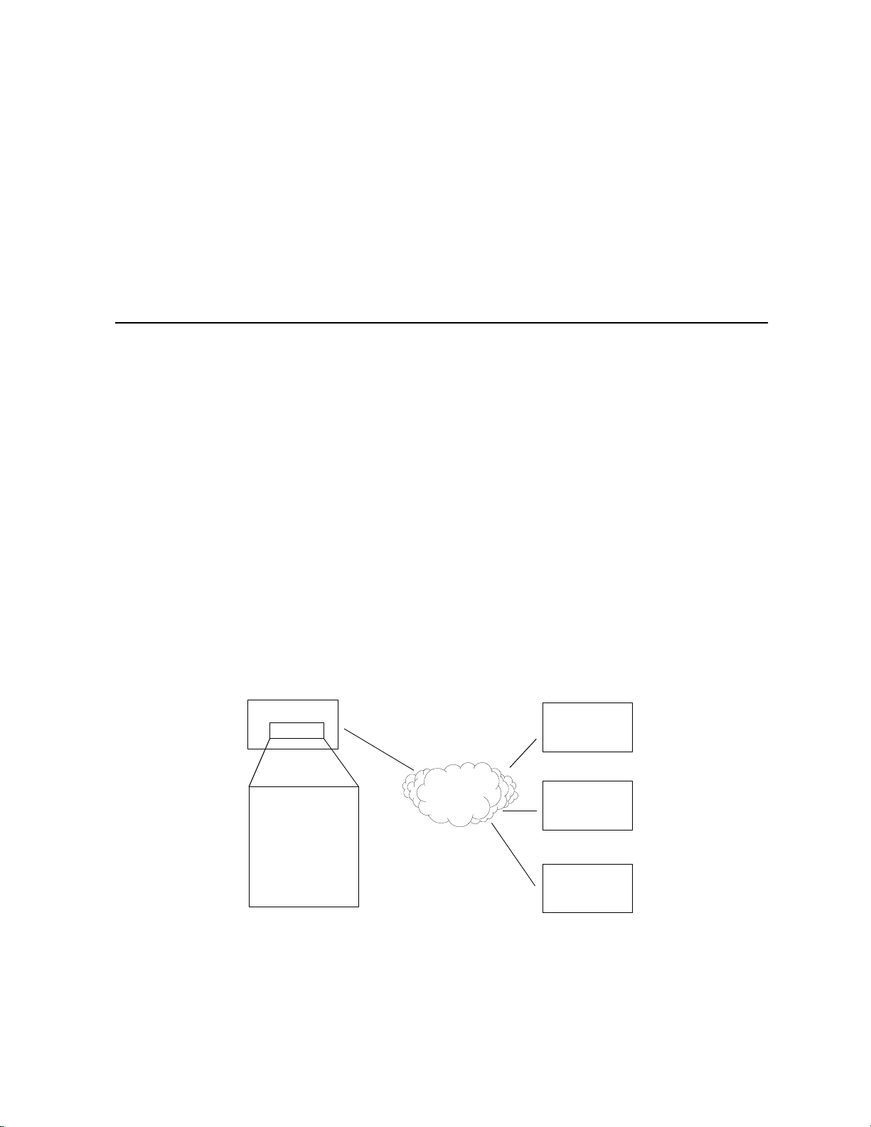
The following diagram illustrates these key words and concepts.
Configuration Process for Router A
TARGET ROUTER
Router A
Target Router:
System Settings
DSL/ATM
local
router
REMOTE ROUTERS
Router B
Router C
.
Remote Router Database
Remote Router B
Remote Router C
Remote Router D
Router D
Chapter 2. Planning for Router Configuration 23
Page 24

Essential Configuration Information
This section describes the configuration information associated with each Link Protocol/Network Protocol
combination and also provides configuration information for the Dual-Ethernet router.
If you are using Link and Network Protocols:
1. Determine which Link Protocol/Network Protocol association you are using from your Network Service
Provider (NSP).
2. Select (click) one of the following Link/Network information that applies to your situation:
PPP Link Protocol with:
• IP Routing Network Protocol, on page 25
• IPX Routing Network Protocol, on page 27
• Bridging Network Protocol, on page 29
RFC 1483 or RFC 1490 Link Protocol with:
• IP Routing Network Protocol, on page 30
• IPX Routing Network Protocol, on page 32
• Bridging Network Protocol, on page 34
MAC Encapsulated Routing: RFC 1483MER or RFC 1490MER Link Protocol with:
• IP Routing Network Protocol, on page 35
FRF8 Link Protocol with:
• IP Routing Network Protocol, on page 37
3. Collect the information applicable to your Link/Network Protocol associatio n. Thi s information will be used
later in conjunction with the
Network protocol. These configuration tables provide step-by-step instructions for a basic configuration for
each Link/Network protocol.
Note:
Use the blank Network Information Worksheets in Appendix A to collect your network information.
If you are using a Dual-Ethernet Router:
Select (click) one of the two following configurations that applies to your situ ation:
Configuring the Dual-Ethernet Router as a Bridge, on page 39
Configuring the Dual-Ethernet Router for IP Routing, on page 39
Configuration Tables
for easy configuration of your router based on your Link/
24 Chapter 2. Planning for Router Configuration
Page 25

PPP Link Protocol (over ATM or Frame Relay)
The PPP Link Protocol is an encapsulation method that can be used over ATM (for ATM routers) or Frame Relay
(for Frame-Relay routers)
Combined with the IP, IPX, or Bridging Network Protocols, PPP over ATM and PPP over Frame Relay share the
same configuration characteristics, except for the connection iden tifiers : VPI/VCI numb ers are us ed f or ATM, an d
a DLCI number is used for Frame Relay.
Select the Network Protocol that applies to your situation: IP or IPX or Bridging. Collect th e information
described in the appropriate section. This data wi ll be later used to conf ig ure yo ur rou ter using the Co mmand Line
Interface commands (see
IP Routing Network Protocol
System Names and Authentication Passwords
!!!!
For the Target Router
Configuration Tables, on page 41).
This information is defined by the user. You must
target router. They are used by a remote router to authenticate the target router.
For the Remote Site(s)
This information is obtained from the Network Service Provider. For each remote site, you
site name and its authentication password. They are used by the target router to authenticate the remote
end. The name and password are used in both PAP and CHAP authentication. Refer to the diagram under
General Security Authentication, on page 15
Note 1:
Configuration 1: PPP with IP and IPX, on page 54
Note 2:
remote disauthen
VPI and VCI Numbers (for ATM routers)
!!!!
Your router may have been preconfigured with VPI/VCI numbers. If not, you will have to obtain these
numbers from your Network Service Provider and then configure them.
If you are connecting to multiple remote sites, you will need to obtain additional VPI and VCI n umb ers
from your Network Service Provider and/or Network Access Provider. These numbers identify the
remote destination and must, therefore, be unique for each remote.
A sample configuration containing names and passwords is provided in the section
If the ISP does not support the authentication of the ISP system by the caller, use the command
remoteName
<
> to disable the authentication.
choose a name and authentication password for the
to see how this information is used.
Chapter 3.
must
Sample
have the
DLCI (for Frame Relay routers)
!!!!
The DLCI number applies to Frame Relay routers only. Your Network Service Provider or your
Network Access Provider will provide you with a Data Link Connection Identifier (DLCI). The DLCI is
an address identifying your connection.
Chapter 2. Planning for Router Configuration 25
Page 26

DNS Internet Account Information (optional)
!!!!
This information is obtained from your Network Service Provider. Consult with you Network Service
Provider to find out if you need to enter the following information:
• DNS server address
• DNS second server address
• DNS domain name
IP Routing Addresses
!!!!
For the Ethernet Interface
This information is defined by the user or your Network Administrator.
Ethernet IP Address (local LAN)
An Ethernet LAN IP address and subnet mask are required for the router’s local Ethernet LAN
connection
Note:
exchange routing information. This feature is not normally used, except in special circumstances.
For the WAN Interface
This information is defined by the Network Service Provider
Source (Target/Local) WAN Port Address
If Network Address Translation (NAT) is enabled, you must specify a source WAN IP address for the
WAN connection to the remote router if IP address negotiation under PPP does not provide one. Check
with your system administrator for details on whether the router must communicate in numbered or
unnumbered mode and which addresses are required.
Remote WAN Address
You may need to specify a remote WAN IP address for the WAN connection to the remote router
depending on IP address negotiation under PPP. Check with your system administrator for details on
whether the router must communicate in numbered or unnumbered mode and which addresses are
required.
TCP/IP Remote Routes
An IP route includes an IP address, subnet mask, and metric (a number representing the perceived cost in
reaching the remote network or station).
.
An Ethernet route is usually defined when there are multiple routers on the Ethernet that cannot
.
TCP/IP Default Route
A
to other specific routes. You will need to define the default route to a remote router or, in special
circumstances, define an Ethernet gateway. There can be only one default route specified.
26 Chapter 2. Planning for Router Configuration
should be designated in the routing table for all traffic that cannot be directed
Page 27

IPX Routing Network Protocol
System Names and Authentication Passwords
!!!!
For the Target Router
This information is defined by the user. You
target router. They are used by a remote router to authenticate the target router.
For the Remote Site(s)
This information is obtained from the Network Service Provider. For each remote site, you
site name and its authentication password. They are used by this target router to authenticate the remote
end. The name and password are used in both PAP and CHAP authentication. Refer to the diagrams
General Security Authentication, on page 15
under
Note 1:
Configurations, on page 54
Note 2:
remote disauthen
VPI and VCI Numbers
!!!!
Your router may have been preconfigured with VPI/VCI numbers. If not, you will have to obtain these
numbers from your Network Service Provider and then configure them.
If you are connecting to multiple remote sites, you will need to obtain additional VPI and VCI n umb ers
from your Network Service Provider and/or Network Access Provider. These numbers identify the
remote destination and must, therefore, be unique for each remote.
A sample configuration containing names and passwords is provided in the section
.
If the ISP does not support the authentication of the ISP system by the caller, use the command
remoteName
<
> to disable the authentication.
must
choose a name and authentication password for the
to see how this information is used.
must
Sample
have the
DLCI (for Frame-Relay Routers)
!!!!
The DLCI number applies to Frame-Relay routers only. Your Network Service Provider or your
Network Access Provider will provide you with a Data Link Connection Identifier (DLCI). The DLCI is
an address identifying your connection.
IPX Routing Entries
!!!!
These numbers are defined by the Network Administrator. You will need to obtain the following
information (most likely from your network administrator) for IPX Routing.
Note: IPX routes
allow the servers and clients to exchange packets. A path to a file server will be based on the Internal
Network Number of the server. A path to a client will be based on the External Network Number
(Ethernet) of the client.
define a
path
to a specific destination. They are primarily needed by the routers to
Chapter 2. Planning for Router Configuration 27
Page 28

Internal Network Number
It is a logical network number that identifies an individual Novell server. It is needed to specify a route to
the services (i.e., file services, print services) that Novell offers. It must be a unique number.
External Network (a.k.a. IPX Network Number)
It refers to a physical LAN/wire network segment to which servers, routers, and PCs are connected
(Ethernet cable-to-router segment). It must be a unique number.
WAN Network Number
Important
between the two routers. Note that only those two routers need to have the WAN Network Number
configured.
Service Advertisement Protocol (SAP)
SAP entries should reflect primary logon servers for the clients on the local LAN. Only the servers on the
remote side of the link have to be entered. Local servers do not need to be entered.
Frame Type
With local servers on your LAN, make sure to select the proper frame type for the IPX network number.
To determine this, consult with your network administrator. When you have only NetWare clients on
your LAN, keep the default (802.2) selected as most clients can support any typ e. The fr ame type cho ices
are:
: This number is part of the routing information. It is only used to identify the WAN segment
802.2
802.3
DIX
becoming obsolete.
Note:
Appendix B provides step-by-step information on how to configure IPX routing.
Default recommended by Novell
Other most common type
For DEC, Intel, Xerox; this setting is also referred to as “Ethernet II”, and it is rapidly
28 Chapter 2. Planning for Router Configuration
Page 29

Bridging Network Protocol
System Names and Authentication Passwords
!!!!
For the Target Router
This information is defined by the user. You
target router. They are used by a remote router to authenticate the target router.
For the Remote Site(s)
!!!!
This information is obtained from the Network Service Provider. For each remote site, you
site name and its authentication password. They are used by the target router to authenticate the remote
end. The name and password are used in both PAP and CHAP authentication. Please refer to the diagram
General Security Authentication, on page 15
under
Note 1:
Configuration 1: PPP with IP and IPX, on page 54.
Note 2:
remote disauthen
VPI and VCI Numbers
!!!!
Your router may have been preconfigured with VPI/VCI numbers. If not, you will have to obtain these
numbers from your Network Service Provider and then configure them.
If you are connecting to multiple remote sites, you will need to obtain additional VPI and VCI n umb ers
from your Network Service Provider and/or Network Access Provider. These numbers identify the
remote destination and must, therefore, be unique for each remote.
A sample configuration containing Names and Passwords is provided in the section Sample
If the ISP does not support the authentication of the ISP system by the caller, use the command
remoteName
<
> to disable the authentication.
must
choose a name and authentication password for the
to see how this information is used.
must
have the
DLCI (for Frame-Relay Routers)
!!!!
The DLCI number applies to Frame-Relay routers only. Your Network Service Provider or your
Network Access Provider will provide you with a Data Link Connection Identifier (DLCI). The DLCI is
an address identifying your connection.
DNS Internet Account Information (optional)
!!!!
This information is obtained from the Network Service Provider. Consult with you Network Ser vice
Provider to find out if you need to enter the following information:
• DNS server address
• DNS second server address
• DNS domain name
Note:
If you intend to connect to the Internet only, enter this information using the Internet Quick Start
configurator.
Chapter 2. Planning for Router Configuration 29
Page 30

RFC 1483/RFC 1490 Link Protocols
The Link Protocol RFC 1483 is a multiprotocol encapsulation method over ATM and is used by ATM routers.
RFC 1490 is a multiprotocol encapsulation method over Frame-Relay and is used by Frame-Relay routers.
RFC 1483 and RFC 1490 com bi ned with th e IP, IP X , or Bri d gi ng Net w or k P rotocols share the same configuration
characteristics, except for the connection identifiers: VPI/VCI numbers are used for RFC 1483 and a DLCI
number is used for RFC 1490.
Obtain the information as described in the appropriate section. This data will be used later to configure your router
using the Command Line Interface (see
IP Routing Network Protocol
VPI and VCI Numbers (for RFC 1483)
!!!!
The VPI and VCI number s apply to ATM routers only. Your router may ha ve been preconfigured with
VPI/VCI numbers. If not, you will have to obtain these numbers from your Network Service Provider
and then configure them.
If you are connecting to multiple remote sites, you will need to obtain additional VPI and VCI n umb ers
from your Network Service Provider and/or Network Access Provider. These numbers identify the
remote destination and must, therefore, be unique for each remote.
Configuration Tables, on page 41).
DLCI (for RFC 1490)
!!!!
The DLCI number applies to Frame-Relay routers only. Your Network Service Provider or your
Network Access Provider will provide you with a Data Link Connection Identifier (DLCI). The DLCI is
an address identifying your connection.
DNS Internet Account Information (optional)
!!!!
This information is obtained from the Network Service Provider. Consult with you Network Service
Provider to find out if you need to enter the following information:
• DNS server address
• DNS second server address
• DNS domain name
IP Routing Entries
!!!!
For the Ethernet Interface
This information is defined by the user or the Network Administrator.
Ethernet IP Address (Local LAN)
An Ethernet LAN IP address and subnet mask are required for the router’s local Ethernet LAN
connection.
30 Chapter 2. Planning for Router Configuration
Page 31

TCP/IP Ethernet Routes
You normally do not need to define an Ethernet IP route. An Ethernet IP route consists of an IP
address, a mask, a metric, and a gateway. An Ethernet route is usually defined when there are multiple
routers on the Ethernet that cannot exchange routing information.
For the WAN Interface
This information is obtained from the Network Administrator.
Source (Target/Local) WAN Port Address
If Network Address Translation (NAT) is enabled, you must
WAN connection to the remote router. Check with your system adminis tr ator f or d e tails.
specify a source WAN IP address for the
If NAT is not
the remote router. Check with your system administrator for details.
TCP/IP Remote Route
An IP route includes an IP address, subnet mask, and metric (a number representing the perceived cost
in reaching the remote network or station).
TCP/IP Default Route
A
cannot be directed to other specific routes. You will need to define the default route to a remote router
or, in special circumstances, define an Ethernet gateway. There can be only one default route specified.
enabled, you may need to specify a source WAN IP address for the WAN connection to
s
default route should be designated in the routing table for all traffic that
Chapter 2. Planning for Router Configuration 31
Page 32

IPX Routing Network Protocol
VPI and VCI Numbers (for RFC 1483)
!!!!
The VPI and VCI number s apply to ATM routers only. Your router may ha ve been preconfigured with
VPI/VCI numbers. If not, you will have to obtain these numbers from your Network Service Provider
and then configure them.
If you are connecting to multiple remote sites, you will need to obtain additional VPI and VCI n umb ers
from your Network Service Provider and/or Network Access Provider. These numbers identify the
remote destination and must, therefore, be unique for each remote.
DLCI (for RFC 1490)
!!!!
The DLCI number applies to Frame Relay routers only. Your Network Service Provider or your
Network Access Provider will provide you with a Data Link Connection Identifier (DLCI). The DLCI is
an address identifying your connection.
IPX Routing Entries
!!!!
The user or the Network Administrator defines this information.
Note: IPX routes
allow the servers and clients to exchange packets. A path to a file server will be based on the Internal
Network Number of the server. A path to a client will be based on the External Network Number
(Ethernet) of the client.
Internal Network Number
This is a logical network number that identifies an individual Novell server. It is needed to specify a
route to the services (i.e., file services, print services) that Novell offers. It must be a unique number.
External Network (a.k.a. IPX Network Number)
This number refers to a physical LAN/wire network segment to which servers, routers, and PCs are
connected (Ethernet cable-to-router segment). It must be a unique number.
WAN Network Number
Important:
between the two routers.
Note:
Only the two routers need to have the WAN Network Number configured.
Service Advertisement Protocol (SAP)
SAP entries should reflect primary logon servers for the clients on the local LAN. Only the servers on the
remote side of the link have to be entered. Local servers do not need to be entered.
define a
This number is part of the routing information. It is only used to identify the WAN segment
path
to a specific destination. They are primarily needed by the routers to
32 Chapter 2. Planning for Router Configuration
Page 33

Frame Type
With local servers on your LAN, make sure to select the proper frame type for the IPX network number.
To determine this, consult with your network administrator. When you have only NetWare clients on
your LAN, keep the default (802.2) selected as most clients can support any type.
The frame type choices are:
802.2
802.3
DIX
becoming obsolete.
Default recommended by Novell
Other most common type
For DEC, Intel, Xerox; this setting is also referred to as “Ethernet II”, and it is rapidly
Chapter 2. Planning for Router Configuration 33
Page 34

Bridging Network Protocol
VPI and VCI Numbers (with RFC 1483)
!!!!
The VPI and VCI number s apply to ATM routers only. Your router may ha ve been preconfigured with
VPI/VCI numbers. If not, you will have to obtain these numbers from your Network Service Provider
and then configure them.
If you are connecting to multiple remote sites, you will need to obtain additional VPI and VCI n umb ers
from your Network Service Provider and/or Network Access Provider. These numbers identify the
remote destination and must, therefore, be unique for each remote.
DLCI (with RFC 1490)
!!!!
The DLCI number applies to Frame-Relay routers only. Your Network Service Provider or your
Network Access Provider will provide you with a Data Link Connection Identifier (DLCI). The DLCI is
an address identifying your connection.
DNS Internet Account Information (optional)
!!!!
This information is obtained from the Network Service Provider. Consult with your Network S ervice
Provider to find out if you need to enter the following information:
• DNS server address
• DNS second server address
• DNS domain name
34 Chapter 2. Planning for Router Configuration
Page 35

MAC Encapsulated Routing: RFC 1483MER/RFC 1490MER Link Protocols
MAC Encapsulated Routing (MER) allows IP packets to be carried as bridged frames (bridged format). The Link
Protocol RFC 1483 with MER (referred to as RFC 1483MER) is a multiprotocol encapsulation method over ATM
used by ATM routers. RFC 1490 with MER (referred to as RFC 1490MER) is a multip roto col encapsulation
method over Frame Relay used by Frame-Relay routers.
RFC 1483MER and RFC 1490MER combined with the IP, IPX, or Bridging Network Protocols share the same
configuration characteristics, except for the connection identifiers: VPI/VCI numbers are used for RFC 1483MER
and a DLCI number is used for RFC 1490.
Obtain the information as described in the appropriate section. This data will be later used to con figure you r ro uter
using the Command Line Interface (see
IP Routing Network Protocol
VPI and VCI Numbers (for RFC 1483MER)
!!!!
The VPI and VCI number s apply to ATM routers only. Your router may ha ve been preconfigured with
VPI/VCI numbers. If not, you will have to obtain these numbers from your Network Service Provider
and then configure them.
Configuration Tables, on page 41).
If you are connecting to multiple remote sites, you will need to obtain additional VPI and VCI n umb ers
from your Network Service Provider and/or Network Access Provider. These numbers identify the
remote destination and must, therefore, be unique for each remote.
DLCI (for RFC 1490MER)
!!!!
The DLCI number applies to Frame Relay routers only. Your Network Service Provider or your
Network Access Provider will provide you with a DLCI (Data Link Connection Identifier). The DLCI is
an address identifying your connection.
DNS Internet Account Information (optional)
!!!!
This information is obtained from the Network Service Provider. Consult with your Network S ervice
Provider to find out if you need to enter the following information:
• DNS server address
• DNS second server address
• DNS domain name
Note:
If you intend to only connect to the Internet, enter this information using the Internet Quick Start
configurator.
Chapter 2. Planning for Router Configuration 35
Page 36

IP Routing Entries
!!!!
For the Ethernet Interface
This information is defined by the user or the Network Administrator.
Ethernet IP Address (Local LAN)
An Ethernet LAN IP address and subnet mask are required for the router’s local Ethernet LAN
connection.
TCP/IP Ethernet Routes
You normally do not need to define an Ethernet IP route. An Ethernet IP route consists of an IP address,
a mask, a metric, and a gateway. An Ethernet route is usually defined when there are multiple routers on
the Ethernet that cannot exchange routing information between them.
For the ATM WAN Interface
This information is obtained from the Network Administrator or the Network Servi ce Prov ider.
Source (Target/Local) WAN Port Address and Mask
You must
not Network Address Translation is enabled). The Source WAN Address is the address of the local ro uter
on the remote network. The mask is the mask used on the remote network. Check with your system
administrator for details.
TCP/IP Remote Routes
If you are using RFC 1483MER or RFC 1490MER, the IP route includes an IP address, subnet mask,
metric (a number representing the perceived cost in reaching the remote network or station), and a
gateway
your system administrator for details.
specify a Source WAN IP address for the WAN connection to the remote router (whether or
. The gateway address that you enter is the address of a router on the remote LAN. Check with
TCP/IP Default Route
A
to other specific routes. You will need to define the default route to a remote router or, in DLCI ( special
circumstances, define an Ethernet gateway. There can be only one default route specified.
should be designated in the routing table for all traffic that cannot be directed
36 Chapter 2. Planning for Router Configuration
Page 37

FRF8 Link Protocol
The FRF8 Link Protocol is an encapsulation method that allows an ATM router to interoperate with a
Frame- Relay network.
FRF8 is only used in conjunction with the IP Network Protocol. Obtain the information described below. This
data will be used later to configure your router using the Command Line Interface (see
page 41).
IP Routing Network Protocol
VPI and VCI Numbers
!!!!
Your router may have been preconfigured with VPI/VCI numbers. If not, you will have to obtain these
numbers from your Network Service Provider and then configure them.
If you are connecting to multiple remote sites, you will need to obtain additional VPI and VCI n umb ers
from your Network Service Provider and/or Network Access Provider. These numbers identify the
remote destination and must, therefore, be unique for each remote.
DNS Internet Account Information (optional)
!!!!
The following information is obtained from the Network Service Provider. Con sult with your NSP to
find out if you need to enter the following information:
Configuration Tables, on
• DNS server address
• DNS second server address
• DNS domain name
Note:
If you intend to connect only to the Internet, enter this information using the Internet Quick Start
configurator.
IP Routing Entries
!!!!
For the Ethernet Interface
This information is defined by the user or the Network Administrator.
Ethernet IP Address (Local LAN)
An Ethernet LAN IP address and subnet mask are required for the router’s local Ethernet LAN
connection.
TCP/IP Ethernet Routes
You normally do not need to define an Ethernet IP route. An Ethernet IP route consists of an IP address,
a mask, a metric, and a gateway. An Ethernet route is usually defined when there are multiple routers on
the Ethernet that cannot exchange routing information.
Chapter 2. Planning for Router Configuration 37
Page 38

For the ATM WAN Interface
This information is obtained from the Network Administrator or the Network Servi ce Prov ider.
Source (Target/Local) WAN Port Address and Mask
You must
not Network Address Translation is enabled. The Source WAN address is the address of the local router
on the remote network. The mask is the mask used on the remote network. Check with your system
administrator for details.
TCP/IP Remote Routes
If you are using FRF8, the IP route includes an IP address, subnet mask, metric (a number representing
the perceived cost in reaching the remote network or station). Check with your system administrator for
details.
A
to other specific routes.
You will need to define the default route to a remote router or, in special circumstances, define an
Ethernet gateway. There can be only one default route specified.
specify a Source WAN IP address for the WAN connection to the remote router (whether or
TCP/IP Default Route
should be designated in the routing table for all traffic that cannot be directed
38 Chapter 2. Planning for Router Configuration
Page 39

Dual-Ethernet Router Configuration
General Information on Dual Ethernet router
To configure the Dual-Ethernet router, access the router using the Command Line Interface (CLI). The CLI
can be accessed from a Telnet or a console session (using the console cable) connected to the router’s default
IP address of 192.169.254.254. You can also configure the router using the Web browser GUI. Refer to the
Dual-Ethernet Router Quick Start Guide
The Dual-Ethernet router has two interfaces:
ETH/0—refers to the router’s hub with four 10Base-T connectors
ETH/1—refers to the single 10Base-T connector
Bridging is enabled by default when the router boots up. IP and IPX routing are disabled.
The router’s default IP address is 192.168.254.254.
DHCP is enabled by default and the router’s DHCP server issues IP addresses to any PC request. The DHCP
default IP pool is 192.168.254. 2 through 192.168.254.20.
To connect to the router, use the router’s default IP address using a Telnet session, for example, and any
10Base-T port on the router.
.
Warning:
You cannot boot from the ETH/1 interface.
Configuring the Dual-Ethernet Router as a Bridge
This router is configured by default as a bridge and no configuration steps are needed. The user needs only
establish a connection to the remote location (to the Internet Service Provider, for example).
Bridging is enabled by default when the router boots up. IP and IPX routing are disabled.
Configuring the Dual-Ethernet Router for IP Routing
eth
The
Ethernet Router Commands (ETH), on page 172,
The last argument of each ETH command determines which interface is being configured (0 for ETH/0, 1 for
ETH/1).
Each interface (ETH/0 and ETH/1) must be set. A minimum of one route must be defined to have a working
configuration. This is generally a default route on the ETH/1 interface where all traffic otherwise specified is
automatically forwarded. This default route is: 0.0.0.0 255.255.255.255 1.
The Gateway address is the IP address supplied by your Internet Service Provider or Network Administrator.
You can customize your router by using the scripting feature, which loads batch files of preset configuration
commands into the router (refer to the
commands are used to configure the Dual-Ethernet router for IP routing. Refer to the section
for usage and syntax information.
Batch File Command Execution, on page 228
section).
Dual-
A Dual-Ethernet router sample configuration with IP Routing is provided in the
Configuring a Dual-Ethernet Router for IP Routing, on page 68
Chapter 2. Planning for Router Configuration 39
section.
Sample Configuration 3:
Page 40

Chapter 3. Configu ri n g Rout e r So ftw a re
This chapter covers configuration tables and verifying the router configuration. It also provides sample
configurations.
Configuration commands are outlined for each
The information needed to configure the router is contingent on the chosen Link Protocol. It is therefore
important to know which Link Protocol you are using (this is determined by your Network Service Provider)
to be able to refer to the configuration sections that apply to your setup.
A configuration table for the Dual-Ethernet Router (with IP routing enabled) is also provided.
The section on verifying the router configuration describes how to test IP, IPX, or Bridging.
In
this chapter, you will find two sample configurations with diagrams, commands , and list outputs.
Note 1:
to Chapter 5. Command Line Interface Reference on page 109
Note 2:
you have installed the router hardware, connected to the router with a terminal-emulation session (or ASCII
terminal), and powered the unit on. This chapter assumes that you have successfully installed the router
hardware as described in the
If you intend to use the Command Line Interface through Configuration Manager, it is assumed that you have
installed the Configuration Manager software and can access the terminal window (refer to the
Guide
Note 3:
remote routers. The worksheets list the commands associated with setting the features.
For usage conventions and a complete description of the commands mentioned in this chapter, refer
To configure the router software, the Command Line Interface is available to you at all times after
Quick Start Guide
).
Worksheets are provided in Appendix A so that you can enter details about your target router and
Link Protocol/Network Protocol
.
.
supported by the router.
Quick Start
To configure the target router, you need to fill out one chart for the target router and one remote router chart
each
for
If you are setting up both ends of the network, you will need a
for configuring the router on the other end of the link.
Important:
changes to take effect:
Ethernet LAN:
Bridging:
Remote Router:
add remote routers
remote router to be entered into the remote router database.
mirror image
If you change any the of the following settings, you must use the commands
Ethernet IP or IPX address, TCP/IP routing, IPX routing
Bridging, Filters
TCP/IP route addresses, IPX routes, IPX SAPs and bridging control, and enable, disable, or
of the information listed below
reboot
and
save
for the
40 Chapter 3. Configuring Router Software
Page 41

Configuration Tables
The following tables give you step-by-step instructions for standard configurations of the following Network
Protocol/Link Protocol associations, as well as a configuration table for a Dual-Ethernet Router:
• PPP Link Protocol with IP Routing Network Protocol
• PPP Link Protocol with IPX Routing Ne t work Protocol
• PPP Link Protocol with Bridging Network Protocol
• RFC 1483/RFC 1490 Link Protocols with IP Routing Network Protocol
• RFC 1483/RFC 1490 Link Protocols with IPX Routing Network Protocol
• RFC 1483/RFC 1490 Link Protocols with Bridging Network Protocol
• RFC 1483MER/RFC 1490MER Link Protocols with IP Network Protocol
• FRF8 Link Protocol with IP Routing Network Protocol
• Mixed Network Protocols (combinations of two or three network protocols)
• Dual-Ethernet Router with IP routing
Note:
Blank Network Configuration Worksheets are available in Appendix A.
Using the tables:
1. Find the configuration table that fits yo ur par ticular Network Protocol/Link Protocol ass ociat ion. These tables
are designed to provide easy step-by-step instructions.
2. Use the blank Network Configuration Worksheets provided in Appendix A to enter the commands in the
order that they are given in the
3. You may want to refer to the sample configurations at the end of this chapter.
Commands
column of the configuration tables.
Chapter 3. Configuring Router Software 41
Page 42

Configuring PPP with IP Routing
This table outlines configuration commands for the PPP Link Protocol with the IP R outing Network Protocol.
PPP with IP Routing
Steps Settings Commands
System Settings
System Name Required
System Message Optional
Authentication Password Required
Ethernet IP Address As required
DHCP Settings Already enabled; additional
settings may be required
Change Login Optional
Remote Routers
New Entry Enter: Remote Name
Link Protocol/PVC
(for ATM routers)
Link Protocol/DLCI
(for Frame Relay routers)
Security
c
a
b
Remote’s Password
Select: PPP
Enter: VPI/VCI numbers
Select: PPP
Enter: DLCI number
Choose security level
Enter: password
Bridging On/Off Must be off
TCP/IP Route Address Enter: Explicit or default
route
If NAT is enabled: To enable NAT, use:
You may need to enter a
Source WAN Port Address
If NAT is not enabled: You may need to enter a
Source WAN Port Address
system name <
system msg <
system passwd <
eth ip addr <
name
message
password
ipaddr
>
>
ipnetmask
> <
>
>
[<
dhcp set valueoption domainname
domainname
<
dhcp set valueoption domainnameserver
system admin <
remote add <
remote setProtocol PPP <
remote setPVC <
remoteName>
<
remote setProtocol PPP <
remote setDLCI <
remote setAuthen <
remote setOurPasswd <
remote disBridge <
remote addIproute <
remoteName
<
remote setIpTranslate
remote setSrcIpAddr <
remoteName
<
remote setSrcIpAddr <
remoteName
<
>
password
remoteName
>
>
remoteName
vpi number
>*<
remoteName
number
> <
protocol> <remoteName
password
remoteName
ipnet
> <
>
remoteName
<
on
ipaddr
>
ipaddr> <mask
>
vci number
remoteName
> <
remoteName
>
ipnetmask
mask
> <
port#
<
ipaddr
>
>
> <
>
>
>
>
>]
>
hop
>
>
>
>
s
IP and IPX Routing
TCP/IP Routing
(Internet Firewall )
Must be enabled
(optional)
IPX Routing Must be disabled
Store
Reboot
a Enter this information if you are using PPP in an ATM environment.
b Enter this information if you are using PPP in a Frame Relay environmen t.
c If the ISP does not support the authentication of the ISP system by the caller, use the command
remoteName
<
> to disable the authentication.
eth ip enable
eth firewall <
eth ipx disable
save
reboot
on | off
>
remote disauthen
42 Chapter 3. Configuring Router Software
Page 43

Configuring PPP with IPX Routing
This table outlines configuration commands for the PPP Link Protocol with the IPX Routi ng Network Protocol.
Note:
Appendix B provides step-by-step information on how to configure IPX routing.
PPP with IPX Routing
Steps Settings Commands
System Settings
System Name Required
System Message Optional
Authentication Password Required
Ethernet IP Address As required
Settings DHCP Already enabled; addit.
settings may be required
Change Login Optional
Ethernet IPX Network # Enter: IPX network #
Frame Type
(default: 802.2)
Remote Routers
New Entry Enter: Remote Name
Link Protocol/PVC
a
(for ATM routers)
Link Protocol/DLCI
(for Frame Relay routers)
Security
c
b
Remote’s Password
Select: PPP
Enter: VPI/VCI numbers
Select: PPP
Enter: DLCI number
Choose security level
Enter: password
Bridging On/Off Must be off
IPX Routes
Enter appropriate info
Add
IPX SAPs
Enter appropriate info
Add
WAN Network # Enter appropriate info
system name <
system msg <
system passwd <
eth ip addr <
dhcp set valueoption domainname
name
message
password
ipaddr
>
>
ipnetmask
> <
>
port#
>[<
>]
<domainname>
dhcp set valueoption domainnameserver <
ipxnet
remoteName
>
socket
> <
password
>
[<
type
>
vpi number
PPP
number
protocol
password
remoteName
<ipxNet
servicename
type
> <
ipxNet
>
port#
>]
>
remoteName
>*<
vci number
remoteName
<
remoteName
> <
remoteName
> <
> <
>
> <
hops
> <
remoteName
> <
>
>
>
>
remoteName
metric
> <
> <
ticks
> <
ipxNet
remoteName
system admin <
eth ipx addr <
eth ipx frame <
remote add <
remote setProtocol PPP <
remote setPVC <
<
remoteName
remote setProtocol
remote setDLCI <
remote setAuthen <
remote setPassw d <
remote disBridge <
remote addIpxroute
remoteName>
<
remote addIpxsap <
ipxNode
<
remote setIpxaddr <
ipaddr
>
>
>
>
>
>
>
IP and IPX Routing
TCP/IP Routing Must be disabled
IPX Routing Must be enabled
Store
Reboot
a Enter this i nformation if you are using PPP in an ATM environment.
b Enter this information if you are usin g PP P in a Fram- Relay environment.
eth ip disable
eth ipx enable
save
reboot
c If the ISP does not support the authentication of the ISP system by the caller, use the command:
remote disauthen
remoteName
<
> to disable the authentication .
Chapter 3. Configuring Router Software 43
Page 44

Configuring PPP with Bridging
This table outlines configuration commands for the PPP Link Protocol with the Bridging Network Protocol.
PPP with Bridging
Steps Settings Commands
System Settings
System Name Required
System Message Optional
Authorization Password Required
DHCP Settings Already enabled; additional
settings may be required
Change Login Optional
Remote Routers
New Entry Enter: Remote Name
Link Protocol/PVC
a
(for ATM routers)
Link Protocol/DLCI
(for Frame Relay routers)
Security
c
Remote’s Password
Select: PPP
Enter: VPI/VCI
b
Select: PPP
Enter: DLCI number
Choose security level
Enter: Password
Bridging On/Off Must be ON
IP and IPX Routing
IP Routing Must be disabled
IPX Routing Must be enabled
Store
Reboot
system name <
system msg <
system passwd <
dhcp set valueoption domainname <
dhcp set valueoption domainnameserver <
system admin <
remote add <
remote setProtocol PPP <
remote setPVC
remote setProtocol PPP <
remote setDLC I <
remote setAuthen <
remote setOurPasswd <
remote enaBridge <
name
>
message
>
password
password
remoteName
vpi number
<
number
protocol
remoteName
>
>
>
remoteName
>*<
vci number
remoteName
remoteName
> <
> <
password
domainname
> <
remoteName
remoteName
remoteName
> <
>
eth ip disable
eth ipx disable
save
reboot
ipaddr
>
>
>
>
>
>
>
>
a Enter this information if you are using PPP in an ATM environment.
b Enter this information if you are using PPP in a Frame-Relay environment.
c If the ISP does not support the authentication of the ISP system by the caller, use the command
<
remoteName
>
to disable the authentication.
remote disauthen
44 Chapter 3. Configuring Router Software
Page 45

Configuring RFC 1483 / RFC 1490 with IP Routing
This table outlines configuration commands for the RFC 1483 and the RFC 1490 Lin k Protocols with the IP
Routing Network Protocol.
RFC 1483 / RFC 1490 with IP Routing
Steps Settings Commands
System Settings
System Message Optional
Ethernet IP Address As required
DHCP Settings Already enabled;
additional settings may
be required
Change Login Optional
New Entry Enter: Remote Name
a
Link Protocol/PVC
(for ATM routers)
Select: RFC 1483
Enter: VPI/VCI
Numbers
b
Link Protocol/DLCI
(for Frame Relay
routers)
Select: FR
Enter: DLCI number
Bridging On/Off Must be OFF
TCP/IP Route
Address
Enter: Explicit or default
route with remote
gateway
If Address T ranslation
To enable NAT, use:
(NAT) is enabled:
system msg <
eth ip addr <
message
ipaddr
>
ipnetmask
> <
dhcp set valueoption domainname <
dhcp set valueoption domainnameserver <
system admin <
password
>
Remote Routers
remote add <
remoteName
>
remote se tProtocol RFC1483 <
>
>
vpi number
remoteName
number
> <
remoteName
> <
ipnet
ipnetmask
>*<
remoteName
remote se tPVC <
remoteName
<
remote se tProtocol FR <
remote setDLCI <
remote disBridge <
remote addiproute <
<
remoteName
remote se tIpTranslate on <
port#
> [<
domainname
remoteName
vci number>
>
remoteName
>
> <
hops
>]
>
ipaddr>
>
>
>
>
TCP/IP Route
Addresses
If NAT is off:
TCP/IP Route
Addresses
Enter: Source WAN Port
Address
You may still need to
enter a Source WAN
Port Address
remote se tSrcIpAddr <
remote se tSrcIpAddr <
ipaddr
ipaddr
> <
> <
mask
mask
remoteName
> <
remoteName
> <
>
>
IP and IPX Routing
TCP/IP Routing
(Internet Firewall )
Must be enabled
(Optional)
IPX Routing Must be disabled
Store
Reboot
a Enter this information i f you are using RFC 1483 in an ATM environment.
Enter this information if you are using RFC 1490 in a Frame-Relay environment
b
eth ip enable
eth firewall <on | off >
eth ipx disable
save
reboot
.
Chapter 3. Configuring Router Software 45
Page 46

Configuring RFC 1483 / RFC 1490 with IPX Routing
This table outlines configuration commands for the RFC 1 483 and RFC 1490 Link Protocols with the IPX
Routing Network Protocol.
Note:
Appendix B provides step-by-step information on how to configure IPX routing.
RFC 1483 / RFC 1490 with IPX Routing
Steps Settings Commands
System Settings
System Message Optional
Ethernet IP Address As required
DHCP Settings Already enabled;
additional settings m ay be
required
Ethernet IPX Network #
Enter: IPX Network # Frame
Type (default is 802.2)
Change Login Optional
Remote Routers
New Entry Enter: Remote Name
Link Protocol/PVC
(for ATM routers)
Link Protocol/DLCI
a
(for Frame Relay routers)
Select: RFC 1483
Enter: VPI/VCI Numbers
Select: FR
Enter: DLCI number
Bridging on/off Must be off
IPX Routes
Enter appropriate info
Add
IPX SAPs
Enter appropriate info
Add
WAN Network Number Enter appropriate info
eth ip addr <
dhcp set valueoption domainna me <
dhcp set valueoption domainna me se rve r <
eth ipx addr <
eth ipx frame <
ipaddr
ipxnet
type
system admin <
remote add <
remoteName
remote setProtocol RFC1483 <
remote setPVC <
<
remoteName
vpi number
>
remote setProtocol FR <
remote setDLCI <
remote disBridge <
remote addIpxroute <
ipnetmask
> <
>
[<
port#
> [<
>]
>
password
>
>
remoteName
>* <
vci number
remoteName
number
remoteName
remoteName
> <
>
ipxNet> <metric> <ticks>
port#
domainname
>
<remoteName>
remote addIpxsap <
ipxNode
<
> <
socket
remote setIpxaddr <
servicename
type
> <
ipxNet
> <
> <
ipxNet
> <
hop
> <
s
remoteName
>]
>
>
ipaddr
>
>
>
>
remoteName>
>
IP and IPX Routing
TCP/IP Routing
(Internet Firewall)
Must be disabled
(optional)
IPX Routing Must be enabled
Store
Reboot
a Enter this information i f you are using RFC 1490 in a Frame Relay environment.
eth ip disable
eth firewall
<on | off >
eth ipx enable
save
reboot
46 Chapter 3. Configuring Router Software
Page 47

Configuring RFC 1483 / RFC 1490 with Bridging
This table outlines configuration commands for the RFC 1 483 and RFC 1490 Link Protocols with the Bridging
Network Protocol.
RFC 1483 / RFC 1490 with Bridging
Steps Settings Commands
System Settings
System Message Optional
DHCP Settings Already enabled;
additional settings may be
required
Change Login Optional
New Entry Enter: Remote Name
Link Protocol/PVC
(for ATM routers)
Link Protocol/DLCI
(for Frame Relay
routers)
Bridging On/Off Must be on
IP Routing Must be disabled
IPX Routing Must b e disabled
Store
Reboot
Enter this information if you are using RFC 1490 in a Frame-Relay environment
a
Select: RFC 1483
Enter: VPI/VCI Numbers
a
Select: FR
Enter: DLCI number
IP and IPX Routing
system msg <
dhcp set valueoption domainname <
dhcp set valueoption domainnameserver <
system admin <
Remote Routers
remote a dd <
remote setProtocol RFC1483 <
remote setPVC <
remoteName
<
remote setProtocol FR <
remote setDLCI <
remote enaBridge <
eth ip disable
eth ipx disab l e
save
reboot
message
remoteName
>
>
password
vpi number
number
remoteName
.
>
>
remoteName
vci number
>*<
remoteName
remoteName
> <
>
domainname
ipaddr
>
>
>
>
>
>
Chapter 3. Configuring Router Software 47
Page 48

Configuring MAC Encapsulated Routing: RFC 1483MER / RFC 1490MER with IP Routing
This table outlines configuration commands for the RFC 1483MER and RFC 1490MER Link Protocols with the
IP Routing Network Protocol.
RFC 1483MER / RFC 1490 MER with IP Routing
Steps Settings Commands
System Settings
System Message Optiona l
Ethernet IP Address As required
DHCP Settings Already enabled;
additional settings may
be required
Change Login Optional
Remote Routers
New Entry Enter: Remote Name
a
Link Protocol/PVC
(for ATM routers)
Link Protocol/DLCI
(for Frame Relay
routers)
Bridging On/Off
TCP/IP Route
Address
Select: RFC 1483MER
Enter: VPI/VCI Numbers
b
Select: MER
Enter: DLCI number
Must be off
Enter: Explicit or default
route with remote
gateway
If NAT is enabled: To enable NAT, use:
If NAT is OFF: Enter: Source WAN Port
Address + mask of the
remote network
TCP/IP Route
Addresses
Enter a Source WAN Port
Address + mask of the
remote network’s mask
system msg <
eth ip addr <
dhcp set valueoption domainname <
message
ipnet
> <
>
ipnetmask
> [<
port#
>]
domainname
dhcp set valueoption domain nameserver <
system admin <
remote add <
remote setProtocol
remote setPVC <
remoteName
<
remote setProtocol MER <
remote setDLCI <
remote disBridge <
remote addiproute <
ipGateway
<
remote setIpTranslate on <
remote setSrcIpAddr <
remote setS rcIpAd dr <
password
remoteName
RFC1483MER
vpi number
>
number
remoteName
remoteName
> <
ipnet
ipaddr
ipaddr
>
>
remoteName
<
vci number
>*<
remoteName
remoteName
> <
>
>
>
ipnetmask><ipGateway
> <
>
remoteName
> <
> <
>
mask><remoteName
mask
remoteName
> <
ipaddr
>
>
>
>
>
>
>
IP and IPX Routing
TCP/IP Routing
(Internet Firewall)
Must be enabled
(optional)
IPX Routing Must be disabled
Store
Reboot
a Enter this information i f you are using RFC 1483 in an ATM environment.
Enter this information if you are using RFC 1490 in a Frame-Relay environment
b
eth ip enable
eth firewall <
eth ipx disable
save
reboot
on | off
.
>
48 Chapter 3. Configuring Router Software
Page 49

Configuring FRF8 with IP Routing
This table outlines configuration commands for the FRF8 Link Protocol with th e IP Routin g N etwork Protocol.
FRF8 with IP Routing
Steps Settings Commands
System Settings
System Message Optiona l
Ethernet IP Address As required
DHCP Settings Already enabled;
additional settings may
be required
Change Login Optional
Remote Routers
New Entry Enter: Remote Name
Link Protocol/PVC Select: FRF8
Enter: VPI/VCI Numbers
Bridging On/Off Must be off
TCP/IP Route
Address
If Address Translation
(NAT) is enabled:
If NAT is OFF: Enter: Source WAN Port
TCP/IP Route
Addresses
Enter: explicit or default
route
To enable NAT, use:
Address + mask of the
remote network
Enter a Source W AN Port
Address + mask of the
remote network
system msg <
eth ip addr <
dhcp set valueoption domainname <
dhcp set valueoption domain nameserver <
system admin <
remote add <
remote setProtocol FRF8 <
remote setPVC <
remoteName
<
remote disBridg e <
remote addIproute <
remoteName
<
remote setIpTranslate on <
remote setSrcIpAddr <
remote setSrcIpAddr <
message
ipaddr
remoteName
>
>
>
> <
password
vpi number
remoteName
ipnet
ipnetmask
>
>
remoteName
vci number
>*<
>
ipnetmask> <hops
> <
remoteName
ipaddr
> <
ipaddr
> <
<port#>
>
[
domainname
>
>
mask><remoteName
mask><remoteName
]
ipaddr
>
>
>
>
>
>
IP and IPX Routing
TCP/IP Routing
(Internet Firewall )
IPX Routing Must be disabled
Store
Reboot
Chapter 3. Configuring Router Software 49
Must be enabled
(Optional)
eth ip enable
eth firewall <
eth ipx disable
save
reboot
on | off
>
Page 50

Configuring Mixed Network Protocols
Several network protocols can be configured concurrently in the same router. The possible combinations are:
• Bridging + IP routing
• Bridging + IPX routing
• Bridging + IP routing + IPX routing
• IP routing + IPX routing
General configuration rules
• IP (and IPX) routing takes precedence over bridging.
• Each network protocol in the combination is individually configured as described in the preceding tables.
• When configuring multiple network protocols,
preceding individual configuration tables show them to be mutually exclusive).
Example
To configuren bridging + IP routing (both with Link Protocol RFC 1483), refer to the preceding
Bridging
Bridging and IP Routing settings. Since you are configuring both bridging and IP routing, make sure that these
two protocols are both enabled (even though the individual configuration tables you are referring to are showing
them to be mutually exclusive). Configure Bridging and then IP Routing. Remember that IP Routin g has
precedence over Bridging.
:
RFC 1483 with IP Routing
and
:
make sure that they are all enabled
tables. Follow the instructions described in the tables, except for the
(even though the
RFC 1483 with
50 Chapter 3. Configuring Router Software
Page 51

Configuring a Dual-Ethernet Router for IP Routing
This table outlines commands used to configure a Dual-Ethernet router for IP routing.
Dual-Ethernet Router with IP Routing
Steps Settings Commands
System Settings
System Name Optional
System Settings
Message Optional
Ethernet Settings
Routing/ Bridging
Controls
ETH/0 IP Address Define ETH/0 IP address for
ETH/1 IP Address Define ETH/1 IP address for
TCP/IP default route
address
DHCP Settings Define DHCP network for
Enable IP routing
Disable bridging
the hub side
the single 10Base-T side
ETH/0 sends all traffic to
ETH/1
DHCP Settings
Already enabled; additional settings may be required
ETH/1
Create an address pool for
ETH/1
DNS Domain Name
system name
system msg
eth ip enable
eth br disable
eth ip addr
eth ip addr
eth ip addroute
<hops> [<port#>
dhcp add | <
<min> <max> <type>
dhcp set addresses
dhcp set valueoption domainname <
<name>
<message>
<ipaddr> <ipnetmask> [<port#>
<ipaddr> <ipnetmask> [<port#>
<ipaddr> <ipnetmask> <gateway>
]
net> <mask> | <ipaddr>
<first ipaddr> <last ipaddr>
]
]
<code>
|
domainname
>
DNS Server
WINS Server Address
Chapter 3. Configuring Router Software 51
dhcp set valueoption domain nameserver
dhcp set valueoption winsserver
<ipaddr>
<ipaddr>
Page 52

Verify the Router Configuration
Test IP Routing
Test IP Routing over the Local Ethernet LAN (from PC)
•Use the TCP/IP
Ethernet LAN IP address.
• If you cannot contact the router, verify that the Ethernet IP address and subnet mask are correct and check the
cable connections.
• Make sure that you have saved and rebooted after setting the IP address.
• Check Network TCP/IP properties under Windows 95. If you are running Windows 3.1, check that you have
a TCP/IP driver installed.
ping
command or a similar method to contact the configured target router specifying the
Test IP Routing to a Remote Destination
• Using the TCP/IP
ping
the
• If remote or local WAN IP Addresses are required, verify that they are valid.
•Use the
specified a default route as well.
command, the router will connect to the remote router using the DSL line.
iproutes
ping
command, contact a remote router from a local LAN-connected PC. When you enter
command to check, first, the contents of the IP routing table and, second, that you have
Test Routing from a Remote Destination
• Have a remote router contact the target router using a similar method.
Test TCP/IP Routes
• Contact a station, subnetwork, or host located on the network beyond a remote router to verify the TCP/IP
route addresses entered in the remote router database.
• Verify that you configured the correct static IP routes.
•Use the
iproutes
command to check the contents of the IP routing table.
Test Bridging to a Remote Destination
Use any application from a local LAN-attached station that accesses a server or disk using a protocol that is being
bridged on the remote network beyond the remote router. If you cannot access the server:
• Verify that you have specified a default destination remote router.
• Make sure that you have enabled bridging to the remote router.
• Check that bridge filtering does not restrict access from the local station.
52 Chapter 3. Configuring Router Software
Page 53

Test IPX Routing
One way to test IPX routing is to check for access to servers on the remote LAN. Under Windows, use the
NetWare Connections
login
type
listed. When you attempt to access the server, the router will connect to the remote router using the DSL line.
If you cannot access the remote server:
• Check that the local Ethernet LAN IPX network number is correct.
• Verify that the WAN link network number is the same as the remote WAN link network number.
• Check cable connections and pinouts.
• Verify that the IPX routes and IPX SAPs you have specified are correct.
on the login drive (usually F:). Select the printer server and verify that the server you have defined is
selection provided with NetWare User Tools. Under DOS, use the command
pconsole
or
• List the contents of the routing and services tables using the
• Make sure that the security authentication method and password that you configured match the remote router.
ipxroutes
and
ipxsaps
commands, respectively.
Chapter 3. Configuring Router Software 53
Page 54

Sample Configurations
Sample Configuration 1: PPP with IP and IPX
This configuration example comprises:
• A scenario describing the configuration
• A diagram showing the configuration of the SOHO router
• Tables containing the configuration settings for this example
• Several
• Information about the names and passwords that are used in this configuration example (required for PPP)
Note:
in Appendix A. Also these samples and others are on the installation CD in the samples directory where the GUI
was installed.
list
command outputs that are used to check the information entered for this particular configuration
Blank Network Information Worksheets are available to fill in the information for your own configuration
Scenario:
In this configuration example of a hypothetical network, a small office/home office (SOHO) will access:
• The Internet through an Internet Service Provider (ISP); it uses PPP as the link protocol with IP routing
as the network protocol. Network Address Translation (NAT) is enabled to the ISP, because the ISP
assigned the SOHO only one IP address.
• A central site (HQ) through a Network Service Provider (NSP provides access to the DSL/ATM Wide
Area Network); it uses PPP as the Link Protocol with IP and IPX as its network protocols.
IP addresses are issued by the DHCP server. DHCP will be set up to issue DNS information to the SOHO LAN.
54 Chapter 3. Configuring Router Software
Page 55

Sample Configuration 1: Diagram for Target Router (SOHO)
Small Home Office SOHO (Target/Local Router)
IPX = 456
0,39
(HQ)
SOHO
0,38
(ISP)
PC/Client
192.168.254.2
255.255.255.0
Workstation/Server
192.168.254.3
255.255.255.0
Target Router
IP:192.168.254.254
255.255.255.0
PPP/IP
192.168.200.20
HQ
ISP
0.0.0.0
255.255.255.255
PPP/IP and IPX
2 Virtual
Circuits
DSL / ATM
Network
Remote Router
IP:172.16.0.1
255.255.255.0
IPX WAN = 789
IPX NET = 123
Network Service
Provider
(ISP)
DNS: 192.168.200.1
DNS Domain: myISP.com
PC/Client
Network Service Provider
(HQ)
Server
SERV312_FP,
1001
NT Server/WINS Server
172.16.0.2
255.255.255.0
Chapter 3. Configuring Router Software 55
Page 56

Sample Configuration 1: Tables for Target Router (SOHO)
SOHO System Settings
Configuration
Section
Name System Name
Message Message (optional)
Authentication
Password
Ethernet IP Address Ethernet IP Address and
Ethernet IPX
Network
DHCP Settings DNS Domain Name
Authentication Password
Subnet Mask
address)
Ethernet IPX Network
Number
DNS Server
WINS Server Address
Item Commands
(default IP
System Settings
system name SOHO
system msg Configured_Dec_1998
system password SOHOpasswd
eth ip addr 192.168.254.254 255.255.255.0
eth ipx addr 456
DHCP Settings
dhcp set valueoption domainname myISP.com
dhcp set valueoption domain nameserver
192.168.200.1
dhcp set valueoption winsserver 172.16.0.2
56 Chapter 3. Configuring Router Software
Page 57

SOHO Remote Router Database
Entry: HQ
Configuration
Section
New Entry Remote Router’s Name
Link Protocol Link Protocol
PVC VPI Number/VCI Number
Security Minimum Authentication
(PAP is the default)
Remote Router’s Password
Bridging Bridging on/off
(Bridging is off by default)
TCP/IP Route
Addresses
IPX Address Network #, Hop Count, Ticks
IPX SAPs SAPS: Server Name, Server
Note:
Fill in one worksheet for each remote router in the remote router database.
Remote Network’s IP
Addresses, Subne t Masks,
and Metric
Type, Network #, Node #,
Sockets, type, hops
WAN Network #
Item Commands
Remote Routers
remote add HQ
remote setProtocol PPP HQ
remote setPVC 0*39 HQ
remote setauthen PAP HQ
remote setpasswd HQ p asswd HQ
remote disbridge HQ
remote addiproute 172.16.0.0 255.255.255.0 1 HQ
remote addipxroute 1001 1 4 HQ
remote addipxsap SERV312_FP 4 1001 00-00-00-
00-00-01 451 3 1 HQ
remote setipxaddr 789 HQ
Chapter 3. Configuring Router Software 57
Page 58

SOHO Remote Router Database
Entry: ISP
Configuration
Section
New Entry Remote Router’s Name
Link Protocol Link Protocol
PVC VPI Number/VCI Number
Security Minimum Authentication
(PAP is the default)
Remote Router’s Password
Bridging Bridging on/off
(Bridging is off by default)
TCP/IP Route
Addresses
a This is needed only if the ISP does not assign an IP address automatically.
Note:
Fill in one worksheet for each remote router in the remote router database
Remote Network’s IP
Addresses, Subne t Masks, and
Metric
Network Address Translation
In Advanced:
Source WAN IP Address and
Subnet Mask
Item Commands
Remote Routers
remote add ISP
remote setProtocol PPP ISP
remote setPVC 0*38 ISP
remote setauthen PAP ISP
remote setpasswd ISPpasswd ISP
remote disbridge ISP
remote addiproute 0.0.0.0 255.255.255.255 1 ISP
(Default Route)
remote setiptranslate on ISP
remote setsrcipaddr 192. 168 .20 0.20 255.255.255 255
ISP
a
SOHO Routing controls
Configur ation
Section
TCP/IP Routing on/off
IPX Routing on/off
Internet Firewall on/off
(Firewall is on by default)
58 Chapter 3. Configuring Router Software
Item Commands
IP and IPX Routing
eth ip enable
eth ipx enable
eth ip firewall on
Page 59

Sample Configuration 1: Check the Configuration with the LIST Commands
Type the following
commands
to obtain a list of your configuration.
system list
GENERAL INFORMATION FOR <SOHO>
System started on.................... 12/1/1998 at 17:41
Authentication override.............. NONE
WAN to WAN Forwarding................. yes
BOOTP/DHCP Server address............ none
Telnet Port.......................... default (23)
SNMP Port.............................. default (161)
System message: configured Dec-1998
remote list
INFORMATION FOR <HQ>
Status............................... enabled
Protocol in use...................... PPP
Authentication....................... enabled
Authentication level required........ PAP
Connection Identifier (VPI*VCI)...... 0*39
IP address translation............... off
Compression Negotiation.............. off
Source IP address/subnet mask........ 0.0.0.0/0.0.0.0
Remote IP address/subnet mask........ 0.0.0.0/0.0.0.0
Send IP RIP to this dest............. no
Send IP default route if known..... no
Receive IP RIP from this dest........ no
Receive IP default route by RIP.... no
Keep this IP destination private..... yes
Total IP remote routes............... 1
172.16.0.0/255.255.255.0/1
IPX network number................... 00000789
Total IPX remote routes.............. 1
00001001/1/4
Total IPX SAPs....................... 1
SERV312_FP 00001001 00:00:00:00:00:01 0451 0003 1
Bridging enabled..................... no
Exchange spanning tree with dest... yes
INFORMATION FOR <ISP>
Status............................... enabled
Protocol in use...................... PPP
Authentication....................... enabled
Authentication level required........ PAP
Connection Identifier (VPI*VCI)...... 0*38
IP address translation............... on
Compression Negotiation.............. off
Source IP address/subnet mask........ 192.168.200.20/255.255.255.255
Remote IP address/subnet mask........ 0.0.0.0/0.0.0.0
Send IP RIP to this dest............. no
Send IP default route if known..... no
Receive IP RIP from this dest........ no
Receive IP default route by RIP.... no
Keep this IP destination private..... yes
Total IP remote routes............... 1
0.0.0.0/255.255.255.255/1
Chapter 3. Configuring Router Software 59
Page 60

IPX network number................... 00000000
Total IPX remote routes.............. 0
Total IPX SAPs....................... 0
Bridging enabled..................... no
Exchange spanning tree with dest... yes
dhcp list
bootp server ................. none
bootp file ................... n/a
DOMAINNAMESERVER (6) ......... 192.168.200.1
DOMAINNAME (15) .............. myISP.com
WINSSERVER (44) .............. 172.16.0.2
Subnet 192.168.254.0, disabled - other DHCP servers detected
When DHCP servers are active . stop
Mask ......................... 255.255.255.0
first ip address ............. 192.168.254.2
last ip address .............. 192.168.254.20
lease ........................ default
bootp ........................ not allowed
bootp server ................. none
bootp file ................... n/a
eth list
ETHERNET INFORMATION FOR <ETHERNET/0>
Hardware MAC address................. 00:20:6F:02:A1:BF
Bridging enabled..................... no
IP Routing enabled................... yes
Firewall filter enabled ........... yes
Send IP RIP to the LAN............. rip-1 compatible
Advertise me as default router... yes
Process IP RIP packets received.... rip-1 compatible
Receive default route by RIP..... yes
RIP Multicast address................ default
IP address/subnet mask............... 192.168.254.254/255.255.255.0
IP static default gateway............ none
IPX Routing enabled.................. yes
External network number............ 00000456
Frame type......................... 802.2
60 Chapter 3. Configuring Router Software
Page 61

Information About Names and Passwords for Sample Configuration 1
In this configuration example, the PPP Link Protocol requires using systems names and passwords.
System Passwords
!!!!
SOHO
has a system password “SOHOpasswd,” which is used when SOHO communicates with HQ for
authentication by that site and at any time when HQ challenges SOHO.
HQ
has a system password “HQpasswd,” which is, likewise, used when HQ communicates with site
SOHO for authentication by SOHO and at any time SOHO challenges HQ.
ISP
has a system password “ISPpasswd” used for the same purpose.
Remote Passwords
!!!!
Each router has a remote router’s password for each remote router defined in its Remote Router
Database. The router will use the remote password to authenticate the remote router when the remote
router communicates with or is challenged by the local site.
For example, SOHO has remote router entries for HQ and ISP; defined in each table entry is the
respective remote router’s password.
The following table shows the names and passwords for each router that must be defined for
authentication to be performed correctly. (This assumes that all three systems use some form of
authentication protocol.)
Note:
If you experience trouble with pass word s, w e recom mend t hat yo u set t he remo te rout er s ecuri ty t o
disable authentication
System
Name
System
Password
Remote
Router
Database
to simplify the process.
Names & Passwords
Configured in
SOHO Router
SOHO HQ ISP
SOHOpasswd HQpasswd ISPpasswd
HQpasswd
ISPpasswd
Names &
Passwords
Configured in
HQ Router
SOHOpasswd SOHOpasswd
Names &
Passwords
Configured in
ISP Router
Chapter 3. Configuring Router Software 61
Page 62

Sample Configuration 2: RFC 1483 with IP and Bridging
This configuration example comprises:
• A scenario describing this configuration of the router SOHO
• A diagram showing the configuration information needed for this example
• Tables containing the configuration settings for this example
• Several
Note 1:
Note 2:
in Appendix A.
list
command outputs that are used to check the information entered for this particular configuration
Names and passwords are
Blank Network Information Worksheets are available to fill in the information for your own configuration
not
required w ith the RFC 14 83 Link Protocol.
Scenario:
In this configuration example of a hypothetical network, a small office/home office (SOHO) will access:
• The Internet through an Internet Service Provider (ISP); it uses RFC 1483 as the Link Protocol with I
routing as the network protocol. Network Address Translation (NAT) is enabled to the ISP, since the ISP
assigned SOHO only one IP address.
• A central site (HQ) through a Network Service Provider (NSP provides access to the DSL/ATM Wide
Area Network); it uses RFC 1483 as the link protocol with bridging and IP routing as its network
protocols.
IP addresses are issued by the DHCP server. DHCP will be set up to iss ue DNS information to the SOHO
LAN.
P
62 Chapter 3. Configuring Router Software
Page 63

Sample Configuration 2: Diagram for Target Router SOHO
Small Home Office SOHO (Target Router)
0,39
(HQ)
SOHO
0,38
(ISP)
PC/Client
192.168.254.2
255.255.255.0
Workstation/Server
192.168.254.3
255.255.255.0
Target Router
IP:192.168.254.254
255.255.255.0
RFC 1483 / IP
192.168.200.20
2 Virtual
Circuits
DSL / ATM
Network
ISP
Network Service
Provider
(ISP)
0.0.0.0
255.255.255.255
DNS: 192.168.200.1
DNS Domain: myISP.com
RFC 1483 / IP + Bridging
PC/Client
Bridging Application
Network Service Provider
(HQ)
HQ
Remote Router
IP:172.16.0.1
255.255.255.0
NT Server/WINS Server
172.16.0.2
255.255.255.0
Chapter 3. Configuring Router Software 63
Page 64

Sample Configuration 2 : Tables for Target Router (SOHO)
SOHO System Settings
Configuration Section Item Commands
System Settings
Message Message (optional)
Ethernet IP Address Ethernet IP Address and
Subnet Mask
(default IP address)
DHCP Settings DNS Domain Name
DNS Server
WINS Server address
system msg RFC1483_dec98
eth ip addr 192.168.254. 254 255.255. 255.0
dhcp set valueoption domainname myISP.com
dhcp set valueoption domainnameserver
192.168.200.1
dhcp set valueoption winsserver 172.16.0.2
SOHO Remote Router Database
Entry: HQ
Configuration Section Item Commands
Remote Routers
New Entry Remote Router’s Name
Link Protocol Link Protocol
PVC VPI Number/VCI Number
Bridging Bridging on/off
TCP/IP Route Addresses Remote Network’s IP
Addresses, Subnet Masks,
and Metric
remote a dd HQ
remote setProtocol RFC1483 HQ
remote setPVC 0*39 HQ
remote enabridge HQ
remote addiproute 172.16.0.0 255.255.255.0 1 HQ
64 Chapter 3. Configuring Router Software
Page 65

SOHO Remote Router Database
Entry: ISP
Configuration
Section
New Entry Remote Router’s Name
Link Protocol Link Protocol
PVC VPI Number/VCI Number
Bridging Bridging On/Off
(Bridging is Off by default)
TCP/IP Route
Addresses
Remote Network’s IP
Addresses, Subnet Masks,
and Metric
Network Address
Translation (NAT)
In Advanced:
Source WAN IP Address
and Subnet Mask
Item Commands
Remote Routers
SOHO Routing Controls
remote add ISP
remote setProtocol RFC1483 ISP
remote setPVC 0*38 ISP
remote disbridge ISP
remote addiproute 0.0.0.0 255.255.255.255 1 ISP
remote setiptranslate on ISP
remote setsrcipaddr 192.168.200.20
255.255.255.255 ISP
Configuration Section Item Commands
IP and IPX Routing
IP and IPX Routing
TCP/IP Routingon/off
IPX Routing on/off
(IPX routing is off by default)
Internet Firewall on/off
(Firewall is on by default)
eth ip enable
eth ipx disable
eth ip firewall on
Chapter 3. Configuring Router Software 65
Page 66

Sample Configuration 2: Check the Configuration with the LIST Commands
system list
GENERAL INFORMATION FOR <SOHO>
System started on.................... 12/1/1998 at 17:48
Authentication override.............. NONE
WAN to WAN Forwarding.................. yes
BOOTP/DHCP Server address............ none
Telnet Port.......................... default (23)
SNMP Port.............................. default (161)
System message: ADSL RFC1483 sample
eth list
ETHERNET INFORMATION FOR <ETHERNET/0>
Hardware MAC address................. 00:20:6F:02:A1:BF
Bridging enabled..................... yes
IP Routing enabled................... yes
Firewall filter enabled ........... yes
Send IP RIP to the LAN............. rip-1 compatible
Advertise me as default router... yes
Process IP RIP packets received.... rip-1 compatible
Receive default route by RIP..... yes
RIP Multicast address................ default
IP address/subnet mask............... 192.168.254.254/255.255.255.0
IP static default gateway.......... none
IPX Routing enabled.................. no
External network number............ 00000000
Frame type.......................... 802.2
remote list
INFORMATION FOR <HQ>
Status............................... enabled
Protocol in use...................... RFC1483 (SNAP)
Connection Identifier (VPI*VCI)...... 0*39
IP address translation............... off
Compression Negotiation.............. off
Source IP address/subnet mask........ 0.0.0.0/0.0.0.0
Remote IP address/subnet mask........ 0.0.0.0/0.0.0.0
Send IP RIP to this dest............. no
Send IP default route if known..... no
Receive IP RIP from this dest........ no
Receive IP default route by RIP.... no
Keep this IP destination private..... yes
Total IP remote routes............... 1
172.16.0.0/255.255.255.0/1
IPX network number................... 00000000
Total IPX remote routes.............. 0
Total IPX SAPs....................... 0
Bridging enabled..................... yes
Exchange spanning tree with dest... yes
INFORMATION FOR <ISP>
Status............................... enabled
Protocol in use...................... RFC1483 (SNAP)
Connection Identifier (VPI*VCI)...... 0*38
IP address translation............... on
66 Chapter 3. Configuring Router Software
Page 67

Compression Negotiation.............. off
Source IP address/subnet mask........ 192.168.200.20/255.255.255.255
Remote IP address/subnet mask........ 0.0.0.0/0.0.0.0
Send IP RIP to this dest............. no
Send IP default route if known..... no
Receive IP RIP from this dest......... .no
Receive IP default route by RIP.... no
Keep this IP destination private..... yes
Total IP remote routes............... 1
0.0.0.0/255.255.255.255/1
IPX network number................... 00000000
Total IPX remote routes.............. 0
Total IPX SAPs....................... 0
Bridging enabled..................... no
Exchange spanning tree with dest.... yes
dhcp list
bootp server ................. none
bootp file ................... n/a
DOMAINNAMESERVER (6) ......... 192.168.200.1
DOMAINNAME (15) .............. myISP.com
WINSSERVER (44) .............. 172.16.0.2
Subnet 192.168.254.0, disabled - other DHCP servers detected
When DHCP servers are active . stop
Mask ......................... 255.255.255.0
first ip address ............. 192.168.254.2
last ip address .............. 192.168.254.20
lease ........................ default
bootp ........................ not allowed
bootp server ................. none
bootp file .................... n/a
Chapter 3. Configuring Router Software 67
Page 68

Sample Configuration 3: Configuring a Dual-Ethernet Router for IP Routing
Scenario:
The following example provides a simple sample configuration for a Dual-Ethernet router (eth_router) with
IP routing enabled.
The router’s hub (ETH/0) belongs to the 192.168.254.0 subnet. The router’s ETH/1 belongs to the
192.168.253.0 subnet.
ETH/0 will route packets to ETH/1 at the address 192.168.253.254. DHCP is enabled for both subnets.
eth_router Configuration
Configuration
Section
Name System Name (optional)
Message Message (optional)
Routing/ Bridging
Controls
ETH/0 IP Address Define ETH/0 IP address for
ETH/1 IP Address Define ETH/1 IP address for
TCP/IP default route
address
DHCP Settings Define DHCP network for
Enable IP routing
Disable bridging
the hub side
the single 10Base-T side
ETH/0 sends all traffic to
ETH/1
ETH/1
Create an address pool for
ETH/1
DNS Domain Name
DNS Server
WINS Server Address
Item Commands
System Settings
Ethernet Settings
DHCP Settings
system name eth_rout e r
system msg Config ured_Jan_1999
eth ip enable
eth br disable
eth ip addr 192.168.254.254 255.255.255.0 0
eth ip addr 192.168.253.254 255.255.255.0 1
eth ip addroute 0.0.0.0 255.255.255.255
192.168.253.254 1 1
dhcp add 192.168.253.0 255.255.255.0
dhcp set addresses 192.168.253.2 192.168.253.20
dhcp set valueoption domainname myISP.com
dhcp set valueoption domain nameserver
192.168.200.1
dhcp set valueoption winsserver 172.16.0.2
68 Chapter 3. Configuring Router Software
Page 69

Chapter 4. Configuring Special Features
The features described in this chapter are advanced topics. They are primarily intended for experienced users and
network administrators to perform network management and more complex configurations.
• Bridge Filtering and IP firewall
• IP protoco l controls (RIP)
• Dynamic Host Configuration Protocol (DHCP)
• Network Address Translation (NAT )
• Management security
• Software options keys
• Encryption
• IP filtering
• L2TP tunneling
Bridge Filtering and IP Firewall
General Information
You can control the flow of packets across the router using bridge filtering. Bridge filtering lets you “deny” or
“allow” packets to cross the network based on position and hexadecimal content within the packet. This enables
you to restrict or forward messages with a specified address, protocol, or data content. Common uses are to
prevent access to remote networks, control unauthorized access to the local network, and limit unnecessary traffic.
For example, it might be necessary to restrict remote access for specific users on the local network. In this case,
bridging filters are defined using the local MAC address for each user to be restricted. Each bridging filter is
specified as a "deny" filter based on the MAC address and position of the address within the packet. “deny”
filtering mode is then enabled to initiate bridge filtering. Every packet with one of the MAC addresses would not
be bridged across the router until “deny” filtering mode was disabled.
Similarly, protocol filtering can be used to prevent a specific protocol from being bridged. In this case, the
protocol id field in a packet is used to deny or allow a packet. You can also restrict, for example, the bridging of
specific broadcast packets.
Configure Bridge Filtering
Bridge filtering allows you to control the packets transfer red acro ss the ro uter. Th is feature can b e used to enh a nce
security or improve performance. Filtering will occur based on matched patterns within the packet at a specified
offset. Two filtering modes are available:
• “Deny” mode will discard any packet matched to the “deny” filters in the filter database and let all other
packets pass.
• “Allow” mode will only pass the packets that match the “allow” filters in the filter database and discar d all
others.
Chapter 4. Configuring Special Features 69
Page 70

Up to 40 “allow” filters or 40 “deny” filters can be activated from the filter database.
Enter the filters, including the pattern, offset, and filter mode, into a filter database. If you intend to restrict
specific stations or subnetworks from bridging, then add the filters with a “deny” designation. Then enable
filtering for “deny”. If you wish to allow only specific stations or subnetworks to bridge, then add the filters with
an “allow” designation and enable filtering for “allow”. Add each filter with the following command:
pos
filter br add
data
[
][
]deny|allow
pos
where [
data and offset number can be used to identify an address, protocol id, or data content. After you have entered all
the filters, verify your entries with the following command:
filter br list
If you have entered an incorrect filter, delete the filter using the
with the filter list, save the filtering database with the
filtering database. Then enable bridging filtering with the following command:
filter br use
Test the filtering configuration by accessing a remote destination identified in the filter .
]
is the byte offset within a packet (number from 0-127) to a [
filter br del
save filter
none|deny|allow
command. You must reboot the router to load the
data
(a hex number up to 6 bytes). This
]
command. When you are satisfied
Enable/Disab le Int e rnet Firewall Filtering
The router supports IP Internet Firewall Filtering to prevent unauthorized access to your system and network
resources from the Internet. This filter discards packets received from the WAN that have a source IP address
recognized as a local LAN address. You can set Internet Firewall Filtering using the command:
eth ip firewall
The Internet Firewall defaults to on during initial configuration and is active
is on.
on|off|list
only
when Ethernet LAN IP routing
As described earlier, Ethernet LAN IP routing is controlled by the commands:
eth ip enable
eth ip disable
Therefore, at initial configuration, you need only enable IP routing to activate the Internet Firewall Filter. If you
do not wish the router to perform IP Internet Firewall Filtering while doing IP routing, you must turn off the
firewall filter.
70 Chapter 4. Configuring Special Features
Remember to save and reboot
if you alter IP routing status.
Page 71

IP (RIP) Protocol Controls
You can configure the router to send and receive RIP packet information, respectively, to and from the remote
router. This means that the local site will “learn” all about the routes beyond the remote router and the remote
router will “learn” all about the local site’s routes. You may not want this to occur in some cases. For example, if
you are connecting to a site outside your company, such as the Internet, you may want to keep knowledge about
your local site’s routes private.
The default is to not send or receive IP RIP packets. If RIP packets are not allowed to flow on the WAN link, you
must
use the
the local site’s existence. The default is to keep the local site’s existence private.
If you wish to allow sending or receiving RIP packets or default routes or to advertise the local site’s existence,
use the following command:
remote addiproute
command to configure static routes for this WAN link. You can also advertise
is:
option>
on|off
[
remote setipoptions <
where <
Note:
option>
rxrip Receive IP RIP packets from the remote destination
rxrip1 Receive and process RIP-1 packets only
rxrip2 Receive and process RIP-2 packet only
rxdef Receive the remote site’s default route
txrip Send IP RIP packets to the remote destination
txrip1 Send RIP-1 packets only
txrip2 Send RIP-2 packets only
txdef Send the local site’s default route
private Keep the local site’s existence private
RIP can be set on the LAN interface as well. See the eth ip options commands for more information.
RIP can be set on the LAN interface as well. See the
remoteName>
] <
eth ip
options commands for more information.
Chapter 4. Configuring Special Features 71
Page 72

Dynamic Host Configuration Protocol (DHCP)
This section describes how to configure DHCP using the Command Line Interface. Configuring DHCP can be a
complex process; this section is therefore intended for network managers. Please refer to Chapter 5 for a complete
list and explanation of the DHCP commands.
General Information
The router supports DHCP and acts as the DHCP server. DHCP is a service that allocates IP addresses
automatically
address.
to any DHCP client (any device attached to your network such as your PC) requesting an IP
DHCP is used to acquire IP addresses and
practical level, acquiring these initialization parameters with DHCP translat es into avoiding the more involved
router/PC manual initialization process (reconfiguration of router and/or PC addresses to be in the same network).
To configure DHCP for a network, the network administrator defines a range of valid IP addresses to be used in
the subnetwork as well as options and other parameters. Once DHCP is configured for the network, each DHCP
client (your PC, for example) can easily request an IP address from the pool of valid IP addresses. The DHCP
client will learn part or all of the network parameters automatically. IP addresses and options assig ned to a client
are collectively called the “lease”. The lease is only valid for a certain period of time and is automatically renewed
by the client. Note that the
some common options.
Before becoming active, the router’s DHCP server attempts to locate other active DHCP servers on the network
such as Windows NT servers. If one is detected, the router’s DHCP server disables itself.
DHCP administration and configuration is divided into the following parts:
• Manipulating subnetworks and explicit client leases
• Setting option values
• BootP
• Defining option types
• Configuring BootP/DHCP relays
• Other information
Note 1:
The TCP/IP stack has to be installed on the PCs for DHCP to work.
Quick Start
options
(such as the subnet mask, DNS, gateway) automatically. On the
configurator does a basic configuration of the DHCP server by asking for
Note 2:
Note 3:
72 Chapter 4. Configuring Special Features
In Windows, DHCP is enabled by selecting it on your PC (under
TCP/IP
To save the DHCP configuration or changes to FLASH memory in the router, make sure to use the
command
in the
dhcp save
Configuration
.
tab page).
Settings, Control Panel, Network,
and
Page 73

Manipulating Subnetworks and Explicit Client Leases
Enabling/Disabling a subnetwork or a Client Lease
To enable/disable a subnetwork or a client lease, use the commands:
net
net
> <
> <
ipaddr
ipaddr
>
>
dhcp enable
dhcp disable
Example:
To enable the subnetwork 192.168.254.0 if that subnetwork exists, type:
dhcp enable 192.168.254.0
To enable the client lease 192.168.254.17 if that client lease exists, enter:
dhcp enable 192.168.254.17
To disable the client lease 192.168.254.18 if that client lease exists, type:
dhcp disable 192.168.254.18
To check the results of these commands, use:
dhcp list
If the client lease does not exist, it must be explicitly created.
all
all
| <
| <
Adding Subnetworks and Client Leases
Adding a Subnetwork
!!!!
The following commands are used to add/delete subnetworks. Only
addresses may be defined for a subnet.
To add a subnetwork, use:
net
net
> <
>
mask
>
dhcp add <
To remove a subnetwork, use:
dhcp del <
Note:
All client leases associated with this subnetwork are automatically deleted.
Example 1:
The following command will create a subnetwork 192.168.254.0 with a subnet mask of 255.255.255.0:
dhcp add 192.168.254.0 255.255.255.0
Example 2:
The following command will delete the subnetwork 192.168.254.0
associated with that subnetwork:
dhcp del 192.168.254.0
one
subnetwork with
and
will delete
one
all
client leases
pool of IP
Chapter 4. Configuring Special Features 73
Page 74

Adding Explicit or Dynamic Client Leases
!!!!
Client leases may either be created dynamically or explicitly. Usually client leases are created
dynamically when PCs boot and ask for IP addresses.
Explicit client leases
To add an explicit client lease, a subnetwork
subnetwork) before the client lease may be added. Use the command:
dhcp add <
To remove a client lease, use:
dhcp del <
Note:
of IP addresses.
Example 1:
To explicitly add the client lease 192.168.254.31, type:
dhcp add 192.168.254.31
Example 2:
To delete the client lease 192.168.254.31, type:
d
hcp del 192.168.254.31
Dynamic Client Leases
Dynamic client leases are created from the pool of IP addresses associated with that subnetwork.
To set or change the pool, use:
dhcp set addresses <
To clear the values from the pool, use:
dhcp clear addresses <
Note:
ipaddr
>
ipaddr
>
An administrator
Any client leases that currently exist will not be affected.
may
create a client lease that is part of a subnet but
first ip addr
net
>
last ip addr
> <
must
already exist (use
>
dhcp add <
net
mask
> <
does not fall within the pool
>
to add the
To remove a client lease that was dynamically created, use:
dhcp del <
Caution:
ipaddr
If <
>
ipaddr
> is a subnet, you will delete the entire subnet.
Setting the L ease Time
Concepts
!!!!
The information given by the DHCP server (router) to your PC is leased for a specific amount of time.
The client lease has already been selected. The DHCP server will select the lease time based on the
option defined for the client lease as described by this algorithm:
1. If the client lease option is a specific number or is infinite, then the server uses the specified lease
time associated with this client lease.
2. If the client lease option is “default”, then the server goes up one level (to the subnetwork) and uses
the lease time explicitly specified for the subnetwork.
74 Chapter 4. Configuring Special Features
Page 75

3. If the client
(global) and uses the lease time defined at the global level (server).
4. Lease time:
The minimum lease time is 1 hour.
The global default is 168 hours.
Commands
!!!!
The following commands are used by network administrators to control lease time.
To set the lease time explicitly for the client lease, use:
dhcp set lease <
To set the lease time explicitly for the subnetwork lease, use:
dhcp set lease <
To set the lease time explicitly for the global lease, use:
dhcp set lease <
Example 1:
To set the lease time to “default” for the client 192.168.254.17, type:
dhcp set lease 192.168.254.17 default
Example 2:
To set the subnetwork lease time to infinite for the subnet 192.168.254.0, type:
dhcp set lease 192.168.254.0 infinite
Example 3:
To set the global lease time to 2 hours, type:
dhcp set lease 2
and
subnetwork lease options are both “default”, then the server goes up one level
ipaddr
net
hours
> <
> <
hours
>
hours
>
>
Manually Changing Client Leases
Administrators will generally not need to change client leases manually. However, if the need arises to do so,
use the following two commands.
Warning
To change the client lease expiration time to a given value:
dhcp set expire <
Setting the expiration time to “default” will cause the server to compute the lease time using the algorithm as
described in Section C
To release the client lease so it becomes available for other assignments:
dhcp clear expire <
: The client will not be aware that the administrator has changed or released a client lease!
ipaddr
ipaddr
hours
> <
, Setting the lease time
>
>
.
Setting Option Values
Administrators will want to set the values for global options, for options specific to a subnetwork, or for options
specific to a client lease.
Note:
See RFC 2131/2132 for the description of various options.
Chapter 4. Configuring Special Features 75
Page 76

Concepts
The server returns values for options explicitly requested in the client request. It selects the values to return
based on the following algorithm:
1. If the value is defined for the client, then the server will return the requested value for an option.
2. If the value for the option has not been set for the client, then the server returns the value option if it has
been defined for the subnetwork.
3. If the value option does not exist for the client
returns the value option if it has been defined globally.
4. If the value option is not defined anywhere, the server will
to the client request.
Important:
•
•
•
•
When the server replies to a client:
It does not
It does not
It does not
has a value defined for t hat option .
It does not
option.
return any option values
support the definition of a “class” of clients.
return any non-default option values
return any non-default values on the clients subnet
not
requested by the client.
and
Commands for Global Option Values
To set the value for a global option, use:
dhcp set valueoption <
The code can be a number between 1 and 61 or a keyword.
To see the list of predefined and user-defined options, use:
dhcp list definedoptions
code
> <
value
>...
does not exist for the subnetwork, then the server
not
return any value for that option in its reply
unless
the client requests the option value
unless
the client requests the value for that
and
the server
To clear the value for a global option, use:
dhcp clear valueoption <
Example:
To set the global value for the domain name server option, enter:
dhcp set valueoption domainnameserver 192.168.254.2 192.168.254.3
code
>
Commands for Specific Option Values for a Subnetwork
To set the value for an option associated with a subnetwork, use:
net
dhcp set valueoption <
To clear the value for an option associated with a subnetwork, use:
dhcp clear valueoption <
Examples:
dhcp set valueoption 192.168.254.0 gateway 192.168.254.254
dhcp set valueoption 6 192.84.210.75 192.84.210.68
76 Chapter 4. Configuring Special Features
> <
net
code
> <
> <
code
value
>
>...
Page 77

Commands for Specific Option Values for a Client Lease
To set the value for an option associated with a specific client, use:
dhcp set valueoption
To clear the value for an option associated with a specific client, use:
dhcp clear valueoption <
Example:
dhcp set valueoption 192.168.254.251 winserver 192.168.254.7
<ipaddr
ipaddr
> <
code
> <
> <
code
value
>
>...
Commands for Listing and Checking Option Values
To list the values for global options as well as subnet and client lease information, use:
dhcp list
To list options that are set for that subnet/client lease as well as subnet/client lease information, use:
net
dhcp list
This command lists all available options (predefined and user-defined options):
dhcp list definedoptions
This command lists all available options starting with the string “name”.
dhcp list definedoptions name
To list the lease time use:
dhcp list lease
<
>|<
ipaddr
>
Example:
This command lists the subnet 192.168.254.0 including any options set specifically for that subnet:
dhcp list 192.168.254.0
BootP
Administrators may wish to specify that certain client leases
About BootP and DHCP
BootP and DHCP provide services that are very similar. However, as an older service, BootP offers only a
subset of the services provided by DHCP.
The main difference between BootP and DHCP is that the client lease expiration for a BootP client is always
infinite
.
Caution:
By default, the DHCP server will
BootP (at the subnetwork or lease level).
Remember that when BootP is enabled, the client assumes that the lease is infinite.
not
satisfy BootP requests unless the adm inistrator has explicitly enabled
and
certain subnetworks can satisfy BootP re quests.
Chapter 4. Configuring Special Features 77
Page 78

Enable/Disable BootP
To allow BootP request processing for a particular client/subnet, use the command:
net
dhcp bootp allow <
>|<
ipaddr
>
To disallow BootP request processing for a particular client/subnet, type:
net
dhcp bootp disallow
<
>|<
ipaddr
>
Use BootP to Speci fy the Boot Server
The following commands let the administrator specify the TFTP server (boot server) and boot file name. The
administrator will first configure the IP address of the TFTP serv er and file name (kern el) fr om which to bo ot.
This is particularly useful if the kernel in the router’s flash is corrupt or does not exist.
To set the IP address of the server and the file to boot from, use the commands:
net
dhcp bootp tftpserver [<
dhcp bootp file [<
net
>|<
>|<
ipaddr
ipaddr
>] <
To clear the IP address of the server and the file to boot from, use:
dhcp bootp tftpserver
[<net>|<
ipaddr
Example 1:
To set the global BootP server IP address to 192.168.254.7:
dhcp bootp tftpserver 192.168.254.7
Example 2:
tftpserver ipaddr
>] <
file name
>] 0.0.0.0
>
>
To set the subnet 192.168.254.0 server IP address to 192.168.254.8:
dhcp bootp tftpserver 192.168.254.0 192.168.254.8
Example 3:
To set the client 192.168.254.21 server IP address to 192.168.254.9
dhcp bootp tftpserver 192.168.254.21 192.168.254.9
Example 4:
To set the subnet 192.168.254.0 boot file to “kernel.100”:
dhcp bootp file 192.168.254.0 kernel.100
Example 5:
To clear the global BootP server IP address and file name:
dhcp bootp tftpserver 0.0.0.0
Example 6:
To clear the subnet 192.168.254.0 server IP address and file name:
dhcp bootp tftpserver 192.168.254.0 0.0.0.0
78 Chapter 4. Configuring Special Features
Page 79

Defining Option Types
Concepts
A DHCP option is a code, length, or value. An option also has a “type” (byte, word, long, longint, binary, IP
address, string).
The subnet mask, router gateway, domain name, domain name servers, NetBios name servers are all DHCP
options. Refer to RFC 1533 if you require more information.
Usually users will
1533 can be shown by typing
not
need to define their own option types. The list of predefined option types based on RFC
dhcp list definedoptions.
Commands
The following commands are available for adding/deleting option types:
dhcp add
To list option types that are currently defined, use:
dhcp list definedoptions...
To list the definitions for all known options, use:
dhcp list definedoptions
To get help information, use:
dhcp list definedoptions?
To list the definition for option 1, if option 1 is defined, type:|
dhcp list definedoptions 1
To list the definition for all options that are well-known AND have a name starting with “h”, type:
dhcp list definedoptions h
Example:
To define a new option with a code of 128, a minimum number of IP addresses of 1, a maximum number of
IP addresses of 4, of type “IP address”, type:
dhcp add 128 1 4 ipAddress
This information implies that:
code
<
> <
min
> <
max
> <
type
>
• Some DHCP client will know about the option with code 128.
• Option 128 allows IP addresses.
• The server can have a minimum of 1 IP address.
• The server can have up to 4 IP addresses.
• The administrator will still need to set the option value either globally, specific to a subnetwork, or
specific to a client for the option to have any meaning.
To delete the definition of the option with code 128, type:
dhcp del 128
Chapter 4. Configuring Special Features 79
Page 80

cannot
not
be
The values for this option that have been set globally, specific to a subnetwork, or specific to a client will
be removed. The administrator must remove those values explicitly. Well-known type option codes
changed or deleted.
Configuring BootP/DHCP Relays
BootP/DHCP Relays are used by system administrators when the DHCP configuration parameters are acquired
from a BootP/DHCP server other than the router’s DHCP server.
This feature allows configuration information to be centrally controlled. Enabling a BootP/DHCP Relay disables
DHCP on the router since (by definition) only one policy mechanism can be supported.
BootP/DHCP Relays are enabled and disabled using the command:
system bootpserver
Other Information
DHCP information is kept in the file DHCP.DAT, a self-contained file.
This file contains
• the option definitions
• the subnetworks that have been added
• the client lease information
• the option values that have been set
This file can be uploaded/downloaded from one router to another.
all
DHCP information including:
Network Address Translation (NAT)
The router supports classic NAT (one NAT IP address assigned to one PC IP address) and a NAT technique
known as masquerading (one single NAT IP address assigned to many PC IP addresses).
General NAT Rules
1. IP routi ng must be enabled.
2. NAT can be run on a per-remote-router basis.
3. Any number of PCs on the LAN may be going to the same or different remote routers at the same time. In
reality, the number of PCs on the LAN that can be supported is limited by how much memory the router
consumes maintaining table information
and
by how many connections are currently active.
4. Some operations will
not work
changed. Remember that the router is remapping both IP addresses and ports.
80 Chapter 4. Configuring Special Features
until the router examines their packets and figures out what information in the data needs to be
not
work. Specifically, services that place IP address/port information in the data
may
Page 81

5. When using NAT with a remote router, either the remote ISP
or the user
6. Any number of PCs on the LAN may have a connection to the same or different remote routers at the same
time. In reality, the number of PCs on the LAN that can be supported is limited by the amount of memory
consumed by the router to maintain table information
are currently active. Theoretically, up to 64,000 active connections per protocol type—TCP/UDP—can be
concurrently running, if the table space is available.
must
configure the IP address for NAT translation locally.
and
must
supply the IP address for NAT translation
by the number of connections the router “thinks”
Masquerading
With masquerading, multiple local (PC) IP addresses are mapped to a single global IP address. Many local ( PCs)
IP addresses are therefore hidden behind a single global IP address. The advantage of this type of NAT is that
users only need one global IP address, but the entire local LAN can still access the Internet. This NAT technique
requires not only remapping IP addresses but also TCP and UDP ports.
Each PC on the LAN side has an IP address and a mask. When the router connects to an ISP, the router appears to
be a “host” with one IP address and mask. The IP address that the router uses to communicate with the ISP is
obtained dynamically (with PPP/IPCP or DHCP) or is statically conf igur ed. When the PC connects to the ISP, the
IP address and port used by the PC are remapped to the IP address assigned to the router. This remapping is done
dynamically.
Client Configuration
Enable NAT
!!!!
To enable NAT, use the commands:
remote setIpTranslate on <
save
save
The
you are connected to this remote router.
Obtain an IP Address for NAT
!!!!
The IP address (the IP address “known” by the remote ISP) used for this type of NAT can be assigned in
two ways.
The ISP dynamically assigns the IP address. Use the commands:
remote setSrcIpAddr
save
The IP address is assigned locally. Use the commands:
remote setSrcIpAddr
save
Note:
command makes the above changes persistent across boots; these changes turn NAT on when
ww.xx.yy.zz
is the IP address that the user on the local LAN assigns.
remoteName
0.0.0.0 0.0.0.0 <
ww.xx.yy.zz
255.255.255.255 <
>
remoteName
>
remoteName
>
Chapter 4. Configuring Special Features 81
Page 82

Server Configuration
This section is intended for users and network administrators who wish to allow WAN access to a Web
server, FTP server, SMTP server, etc., on their local LAN, while using NAT.
NAT needs a way to identify which local PC [local IP address(es)] should receive these server requests.
The servers can be configured on a
Remote Commands
!!!!
The following two commands are used to enable/disable a local IP address (on your LAN) as the server
for a particular protocol for the remote router
per-remote-router
<remoteName
basis as well as
globally.
>.
remote addServer
last port
[<
remote delServer
last port
[<
where
first port:
last port:
for the server on your LAN.
first private port:
first port
first port
last port
first port
first private port
the server on your local LAN will receive the request.
This command is used to view all of the remote entries, including the changes.
remote list <
>[<
>[<
this is the first or only port as seen by the remote end.
if specified, this is used with <
maps to
+ 1 maps to
maps to
through
remoteName
ipaddr
<
first private port
ipaddr
<
first private port
if specified, this is a port remapping of the incoming request from the remote end.
first private port
first private port
last port
through
> |discard|me <
>]] <
> |discard|me <
>]] <
.
first private port
+
are the ports as seen by the remote end.
first private port
>
protocolid
remoteName
protocolid
remoteName
first port
+ 1.
last port
-
last port
+
> tcp|udp <
>
> tcp|udp <
>
> to specify a range of ports as seen by the remote end
first port
first port
-
first port
first port
are the equivalent ports through which
> ftp|telnet|smtp|snmp|http
> ftp|telnet|smtp|snmp|http
Remember to type
Example 1:
Assume that the local LAN network is 192.168.1.0 255.255.255.0. The following commands are typed to
enable a Telnet server on the local LAN with the IP address 192.168.1.3, and an FTP server with the IP
address 192.168.1.2.
remote addServer 192.168.1.3 tcp telnet router1
remote addServer 192.168.1.2 tcp ftp router1
When the local router receives a request from
local router will send the request to 192.168.1.3. If
router will send the request to 192.168.1.2.
Example 2:
Assume that the local LAN network is 192.168.1.0 255.255.255.0. When the port value of 0 (zero) is
used, it directs all ports of the specified protocol to the IP address specified.
remote addServer 192.168.1.4 tcp 0 router1
82 Chapter 4. Configuring Special Features
save
to make the changes persistent across boots.
router1
to communicate with the local Telnet server, the
router1
asks to talk to the local FTP server, the local
Page 83

Note: addserver
192.168.1 .4 will be ask ed to serve requests coming from
also has the same Telnet and FTP entries from the previous example, 192.168.1.3 will serve the Telnet
request, 192.168.1.2 will serve the FTP request, and 192.168.1.4 will serve any other request, including
HTTP, SMTP, etc.
Example 3:
remote addServer 192.168.1.10 tcp 9000 9000 telnet route-in
remote addServer 192.168.1.11 tcp 9001 9001 telnet route-in
In this example, an incoming request on TCP port 9000 will be sent to 192.168.1.10 with the port
changed from 9000 to the Telnet (port 23).
An incoming request on TCP port 9001 will be sent to 192.168.1.11 with the port changed from 9001 to
the telnet port.
“Failed to add server” error message
commands using specific port numbers take priority over the port 0 setting.
router1
to the local router. If the local router
The error message
for two reasons:
Port overlap:
enter:
remote addserver 192.168.1.10 tcp 9000 9000 telnet router1
Let us assume this command is accepted. Then you enter:
remote addserver 192.168.1.11 tcp 9000 9000 telnet router1
Let us assume this command gets an error. If the remote end send s a se rver requ est to port 90 00, it can not
know to which server, 192.168.1.10 or 192.168.1.11, to send the request, if both entries exist.
Not enough memory was available to create an entry.
because the amount of memory needed for a server entry is less than 30 bytes. Should this problem
occur, it may cause many related problems or failures.
System Commands
!!!!
The following two commands are used to globally enable/disable a local IP add ress (o n yo ur LAN) as the
server for that particular protocol.
system addServer
last port
[<
>[<
Failed to add server
One or more of the ports would be visible to the remote end overlap. For example, you
ipaddr
<
first private port
> discard|me <
>]]
is printed if a server entry could not be created. This can occur
This condition should not ordinarily occur
protocolid
> tcp|udp <
first port
> ftp|telnet|smtp|snmp|http
system delServer
port
where
first port:
last port:
the server on your LAN.
Chapter 4. Configuring Special Features 83
first private port
>[<
this is the first or only port as seen by the remote end.
if specified, it is used with <
ipaddr
<
> discard|me <
>]]
protocolid
first port
> tcp|udp <
> to specify a range of ports as seen by the remote end for
first port
> ftp|telnet|smtp|snmp|http [<
last
Page 84

first private port:
first port
first port
maps to
+ 1 maps to
if specified, this is a port remapping of the incoming request from the remote end.
first private port.
first private port
+ 1
last port
first port
first private port
your local LAN will receive the request.
Remember to type
Examples:
system addserver 192.168.1.5 tcp smtp
system addserver 192.168.1.6 tcp 0
system addserver 192.168.1.6 udp 0
The router sends a server request for SMTP to 192.168.1.5 when such a request comes from any remote
router running NAT. The router sends any other server request (tcp or udp) to 192.168.1.6.
Server Request Hierarchy
!!!!
When handling a request from a remote router (to which the local router has NAT enabled), the local
router selects a server based on the following priority algorithm:
maps to
through
first private port
last port
through
are the ports as seen by the remote end.
first private port
save
to make the changes persistent across boots.
last port
+
-
last port
+
first port
first port
-
are the equivalent ports the server on
remote addserver
1.
particular protocol/port.
system addserver
2.
port.
remote addserver
3.
that particular protocol (such as tcp/udp) and
system addserver
4.
protocol and
5. If an IP address is used for true NAT host remapping as well as for IP address/port translation, the IP
address of the local remapped host as the server is selected.
6. Router’s
IP address
— The local router selects a server for the remote router that handles that
— The local router selects a global server that handles that particular protocol/
port
any
with
with
port.
— The local router selects itself (the local router) as the server.
0 — The local router selects a server for the remote router that handles
any
port.
port
0 — The local router selects a global server that handles that particular
Classic NAT
With classic NAT, one PC IP address is translated to one NAT IP address. This NAT technique is primarily used
to make certain hosts on a private LAN globally visible and give them the ability to remap these IP addresses as
well.
84 Chapter 4. Configuring Special Features
Page 85

Client Configuration
Classic NAT requires that you first enable NAT Masquerading (as describe d in th e prev ious section); thus,
for the Classic and Masquerading forms of NAT, the clients are configured in the same way. Refer to the
Client Configuration, page 81
Host Remapping
Remote Commands
!!!!
Use the following two commands to enable or disable host remapping on a per-remote basis:
remote addHostMapping <
remoteName
<
>
section.
first private addr
second private addr
> <
first publ i c addr
> <
>
remote delHostMapping <
remoteName
<
Use the command
addresses to different remotes.
System Commands
!!!!
Use these commands to enable or disable host remapping systemwide:
system addHostMapping
system delHostMapping <
Use the command
address on all remotes.
IP Address Range
!!!!
The range of local LAN IP addresses to be remapped is defined by <
private addr
The range of public IP address es i s defined by <
automatically (from <
inclusive.
>
remote addHostMapping
system addHostMapping
> inclusive. These addresses are mapped one-to-one to the public addresses.
first private addr
first private addr
<
first private addr
first public addr
> to <
second private addr> <first pub li c a ddr
> <
whenever a host on the local LAN is known by different IP
second private addr> <first public addr
> <
second private addr
> <
whenever a host on the local LAN is known by the same IP
first public addr
first pub li c a ddr
>
>
first public addr
> <
first private addr
> only. The rest of the range is computed
> + number of addresses r emapped - 1)
>
<second
> to
Chapter 4. Configuring Special Features 85
Page 86

Multiple-Host Remapping Entries
!!!!
Users may enter as many host remapping entries as they wish.
Example:
remote addHostMapping 192.168.207.40 192.168.207.49 10.0.20.11
remoteName
remote addHostMapping 192.168.207.93 192.168.207.99 10.0.20.4
remoteName
remote addHostMapping 192.168.209.71 192.168.209.80 10.12.14.16
remoteName
The above entries create three mappings:
192.168.207.40 through 192.168.207.49 are mapped to 10.0.20.11 through 10.0.20.20
192.168.207.93 through 192.168.207.99 are mapped to 10.0.20.4 through 10.0.20.10
192.168.209.71 through 192.168.209.80 are mapped to 10.12.14.16 through 10.12.14.25
Range Overlap Rules
!!!!
remote addHostMapping,
With
remote addHostMapping
With
system addHostMa pping
With
system addHostMa pping
With
private IP address ranges cannot overlap for a remote router.
, public IP address ranges cannot overlap for a remote router.
, private IP address ranges cannot overlap for a system.
, public IP address ranges cannot overlap for a system.
If a private IP address range for a remote router and a private IP address range for the system overlap, the
private IP address range for the remote has precedence.
If a public IP address range for a remote and the public IP address range for the system overlap, the
public IP address range for the remote has precedence.
Private IP addresses and public IP addresses can be the same
For example, to enable IP/port translation to a remote router and make the IP addresses 10.1.1.7 through
10.1.1.10 globally visible, it is permissible to use either one of the following commands:
remote addHostMapping 10.1.1.7 10.1.1.10 10.1.1.7 remoteName
system addHostMapping 10.1.1.7 10.1.1.10 10.1.1.7
If the remapped host’s IP address (classic NAT, one-to-one IP address translation) and the masquerading
IP address (many-to-one IP address translation) are the same, then NAT masquerading has precedence
over classic NAT.
.
86 Chapter 4. Configuring Special Features
Page 87

Management Security
With the following security control features, the user can prevent the router from being remotely managed via
Telnet and/or SNMP. Disabling SNMP will stop the Configuration Manager from accessing the router, which in
some environments is desirable.
Disable Telnet and SNMP
To completely disable remote management, the following commands should be entered from the command line.
login admin
system telnetport disable
system snmpport disable
save
reboot
Restore Telnet and SNMP
To reestablish the Telnet and SNMP services, the default values should be restored with the commands:
system telnetport default
system snmpport default
Validation of Telnet and SNMP Clients
The following commands are used to validate Telnet, SNMP, or HTTP clients. They define a range of IP
addresses that are allowed to access the router via Telnet, SNMP, or HTTP. Only the IP addresses in the range
specified for Telnet, SNMP, or HTTP can access the router via Telnet, SNMP, or HTTP. This validation feature is
off
by default.
system addtelnetFilter <
system addSNMPFilter <
system addHTTPFilter <
where:
first ip addr
last ip addr
LAN Local Ethernet LAN
Example:
system addsnmpfilter 192.168.1.5 192.168.1.12
Multiple ranges can be specified for Telnet and SNMP clients. If no range is defined, then access to the router is
through the LAN or WAN.
Note 1:
These commands do
First IP address of the client range
Last IP address of the client range. May be omitted if the range contains only one IP address.
first ip addr
first ip addr
first ip ad dr
not
require a reboot and are effective immediately.
last ip addr
> [<
last ip addr
> [<
last ip addr
> [<
>] | LAN
>] | LAN
>] | LAN
Note 2:
Chapter 4. Configuring Special Features 87
The following commands are used to delete client ranges previously defined by the
addtelnetFilter, system addSNMPFilter,
system addHTTPFilter
and
commands:
system
Page 88

system deltelnetFilter <
first ip addr
last ip addr
> [<
>] | LAN
Note 3:
system delSNMPFi l ter <
system delHTTPFilter <
To list the range of allowed clients, use the command
write permission (login with password).
first ip addr
first ip addr
last ip addr
> [<
last ip addr
> [<
>] | LAN
>] | LAN
system list
when you are logged in with read and
Restrict Remote Access
To allow management via SNMP or Telnet, while making it more difficult for non-authorized persons to access
the router, you may redefine the Telnet and SNMP ports to a non well-known value. When Network Address
Translation (NAT) is used, this port redefinition feature also allows you to continue using the standard Telnet and
SNMP ports with another device on the LAN (provided the appropriate NAT server ports commands are issued),
while simultaneously managing the router (with non-standard ports). The following commands show how this is
done.
Example:
login admin
system telnetport 4321
system snmpport 3214
Changing the SNMP Community Name
Changing the SNMP community name from its default value of “public” to another string may further enhance
SNMP security. This string then acts like a password, but this password is sent in the clear o ver th e WAN/LAN, in
accordance with the SNMP specification.
Use the following commands to change the SNMP community name.
login admin
system community
save
reboot
snmp community name
<
-- (e.g.,
>
system community fred)
Disable WAN Management
You may wish to allow management of the router on the local LAN, but not over the WAN. If the router has been
configured to use NAT, you can define two servers that
Telnet requests, and thus WAN management of the router cannot occur. The following commands show how this
could be done.
Example:
login admin
system addServer 192.168.254.128 udp snmp - (no computer at 192.168.254.128)
system addServer 192.168.254.128 tcp telnet
save
reboot
do not
exist on the LAN side to handle WAN SNMP and
88 Chapter 4. Configuring Special Features
Page 89

System Log
system syslogport default|disabled|<port>
To manage the system log default when the port becomes disabled.
system addSyslogFilter <first ip address>[<last ip addr>]
When system log is filtered from the ip address: first or last.
system addSyslogFilter LAN
The Filter allows LAN access while using the filter.
Software Option Keys
This router has several optional software features that can be purchased as software option keys, when ordering
the router. These optional features are:
• DES encryption (for more information, refer to
• IP filters (for more information, refer to
• L2TP Tunneling (for more information, refer to
These options are usually ordered with the router.
To find out which software options are installed on your router, use the
vers
command follows:
Maximum users: unlimited
Options: SDSL, IP, ~IP FILTERING, IP TRANS, HOST MAPPING, DHCP, ~L2TP,
~ENCRYPT, BRIDGE, IPX
The features that are present in the firmware, but not are not enabled are preceded by a "~". These features can be
enabled a software key that can be purchased from your distributor.
To install a software options key that has been purchased separately, follow the instructions provided with that
key.
Encryption, page 89
IP Filtering, page 93
L2TP Tunneling — Virtual Dial-Up, page 96
)
)
)
vers
command. A sample output of the
Encryption
Note:
Encryption is a software option. The following section applies only for routers with this o pt ion.
For routers shipped with the following encryption options, two variants of encrypted data links over PPP have
been implemented:
• PPP DES (Data Encryption Standard) (RFC1969)
Chapter 4. Configuring Special Features 89
Page 90

• Diffie-Hellman
Encryption requires PPP.
Caution:
Canada.
PPP DES and Diffie-Hellman encryption options may not be exported outside the United States or
PPP DES (RFC 1969) Encryption
PPP DES (Data Encryption Standard) implementation uses a 56-bit key with fixed
are specified in each router. With RFC 1969 , users mu st man age th e key s. This implementation has been tested for
interoperability with other PPP DES vendors such as IBM and Network Express (part of Cabletron).
transmit
Configuration Notes
Simply add the encryption commands to your standard configuration. For PPP DES, the encryption
commands are:
key
key
> <
> <
remoteName
remoteName
system log
>
>
receive
command) to view error messages and p rog ress .
key and
sender Tx
key don't match.
remote setEncryption dese rx <
remote setEncryption dese tx <
Observe the following guidelines:
• PPP DES can only be configured using the Command Line Interface (CLI).
• The choice of keys should be carefully considered: they must have eight hexadecimal digits, and values
that are considered cryptographically weak should be avoided. Consult a security expert for advice.
• Use the console port or a Telnet port (use the
If you see “Unknown protocol” errors, the router
and
receive
keys that
• Different keys may be used with different remote destinations.
• For maximum security, as shown in the following configuration examples, Telnet and SNMP access
should be disabled, and PPP CHAP authentication should be used by both ends.
Sample Configuration
Refer to the section
(the remote router) are configured in the same manner as shown in Chapter 3, but the following encryption
commands are added. Don’t forget to save the configuration and reboot the router (
commands).
Remember that the
SOHO is the
Use this sample configuration with the additional encryption commands as a guideline to confi gur e your o wn
routers.
Enable Encryption on the Router HQ
!!!!
Sample:
login: *****
remote setEncryption dese rx 1111111111111111 SOHO
Sample Configurations 54
transmit
transmit
key (tx) of SOHO is the
key of HQ.
,
of this guide. The routers SOHO (the target router) and HQ
receive
save
key (rx) of HQ. Inversely, the
and
reboot
receive
key of
90 Chapter 4. Configuring Special Features
Page 91

remote setEncryption dese tx 2222222222222222 SOHO
save
reboot
Enable encryption for the router SOHO
!!!!
Sample:
remote setEncryption dese tx 1111111111111111 HQ
login: *****
remote setEncryption dese rx 2222222222222222 HQ
save
reboot
Chapter 4. Configuring Special Features 91
Page 92

Diffie-Hellman Encryption
With Diffie-Hellman encryption, each router has an encryption file that is associated with a public key providing
768-bit security. The predefined keys can be replaced by the user. The key files have a suffix of “num” by
convention (e.g., dh96.num).
Configuration Notes
Simply add the encryption command to your standard configuration. For Diffie-Hellman, the encryption
command is:
remote setEncryption
Observe the following guidelines:
• DESE_1_KEY specifies that the same key is used in both directions, whereas DESE_2_KEY specifies
that the keys are different. Having the same keys in both directions can significantly reduce time needed
to compute the DES keys from the Diffie-Hellman exchange.
• routers’
• Different keys and key files may be used with different remote destinations.
• For maximum security, as shown in these examples, Telnet and SNMP access should be disabled, and
PPP CHAP should be used. Use the console port to view error messages and progress.
receive
DESE_1_KEY|DESE_2_KEY [
key and
sender
Tx key don't match.
<fileName>]| <remoteName
>
Sample Configuration
The sample configuration is the same as the one provided in the preceding PPP DES encryption example, but
the Diffie-Hellman encryption comman d is us ed in stead of the PPP DES encryption commands.
Sample:
login admin
remote setEncryption DESE_1_KEY dh96.num SOHO
save
reboot
File Format for the Diffie-Hellman Number File
The file consists of 192 bytes, in binary format. There are two 96-byte numbers stored, with the most
significant byte in the first position. For example, the number 0x12345678 would appear as
000000...0012345678.
The first 96 bytes form the modulus. In the equation
and Hellman, the modulus should be prime, and
The second 96 bytes form the generator, or g in the above equation. The generator should be a primitive root
mod n.
The remaining pieces of the encryption key (x and y) are randomly generated at connection time and will
change every time the device connects.
Contact an encryption expert to obtain cryptographically sound generator and mod ulus pairs if you wish to
change the default values.
92 Chapter 4. Configuring Special Features
x' = g^x mod n, n
(n-1)/2
should also be prime.
is the modulus. According to Diffie
Page 93

Default Modulus
!!!!
00000000: c9 b4 ed 33 ba 7f 00 9e - ce e0 83 5d a5 4c 19 25
00000010: e0 2d 99 44 e8 8d cd 16 - 02 0e 6c 26 6d 15 7c 95
00000020: 82 9a 8c 2b 19 d0 56 da - 9b 5b a9 cd cf fb 45 2b
00000030: c9 6a 3c 26 e5 b8 1a 25 - 07 b8 07 22 ed 15 8a 56
00000040: 8b f4 30 f2 28 fc 6b f1 - bf a4 3e 87 f0 be d6 1c
00000050: 33 92 b9 5e d1 b7 20 8c - 92 02 cb e5 26 45 02 1d
Default Generator
!!!!
00000000: 90 f0 09 78 cc 23 79 a8 - 6c 23 a8 65 e0 dc 0f 6d
00000010: fb a7 26 e8 63 0a 21 67 - 5a f8 0f 59 84 09 5c da
00000020: ef af af fc d2 5f 83 e2 - a7 27 05 34 17 94 1a 4f
00000030: b2 87 76 97 e7 48 43 db - 62 29 70 9e 7f eb 2c 6e
00000040: 5d 25 1d a1 65 f0 b4 e6 - 47 4d 25 23 0b 20 b9 93
00000050: 27 f0 56 12 5a 97 f6 c5 - 31 b6 19 fc 67 22 93 f5
IP Filtering
Note:
Filtering is a software option. The following section applies only for rout ers with this option.
IP Filtering is a type of firewall used to control network traffic. The process involves filtering packets received
from one interface and deciding whether to route them to another interface or discard them.
When it is filtering packets, the router examines information such as the source and destination address co nt ained
in the IP packet, the type of connection, etc., and then screens (filters) the packets based on this information;
packets are either allowed to be forwarded from one interface to another interface or simply discarded.
IP filtering requires IP routing to be enabled. This type of filtering offers great flexibility and control of IP filters,
but configuration of this feature requires using a series of commands that may appear complex to a casual user.
Filters and Interfaces
Filters are commands used to screen IP packets: packets are simply matched against a series of filters. The result
is that packets are either allowed to come through the interface/link or they are dropped. If no filter “matches” the
incoming packet, the packet is accepted by default.
Filters operate at the interface level. Each interface has a series of IP filters associated with it and is defined by
three types of filters: Input filters, Output filters, and Forward filters. A list of filters is created for each interface.
The following illustrates the filter process.
Chapter 4. Configuring Special Features 93
Page 94

Input Phase
1 2
Input
Filter
Forward Phase
3
N
A
T
IP-ES
ICMP
Redirect
Forward
Filters
IP Routing
Table
Output Phase
4 5
N
Output
A
Filter
T
Forward filters on
the input interface
Routing
Table
Processing
Forward filters on
the output interface
In the following description of the Input, Forward, and Output phases, the reference numbers associated with
filtering steps match the numbers used in the above illustration.
Input Phase
When an IP packet comes in through an interface (i.e., the Input interface), the router tries to recognize the
packet. The router then examines the Input filters for this interface and, based on the first Input filter that
matches the IP packet, it decides how to handle the packet (forward or discard it).
If NAT translation is enabled for the Input interface, NAT translation is performed.
Forward Phase
At this stage, the router determines to which interface or link the packets will be sent out using its routing
table. It then applies the Forward filters based on the Input interface information. Next the router applies the
Forward filters based on the Output interface information.
Output Phase
If NAT translation is enabled for the Output interface, then NAT translation is performed. The router
examines the Output filters for this interface and, based on the first Output filter that matches the IP packet, it
decides how to handle the packet.
Configuring Filters with Network Address Translation Enabled
General NAT Information
Network Address Translation is an IP address con versi on feature that trans lates a PC’s local ( int ernal) addr ess
into a global (outside/Internet) IP address. NAT is needed when a PC (or several PCs) on a Local Area
Network wants to connect to the Internet or get to a remote network that uses global, registered addresses:
94 Chapter 4. Configuring Special Features
Page 95

NAT swaps the local IP address with a global IP address: the IP address and port information that the PC uses
are remapped (changed) to the IP address that was assigned to the router and a new port number is assigned.
Note:
The preceding section,
Filters and Interfaces
, describes how NAT “behaves” for each filtering phase.
Filter Actions
For an IP packet to be forwarded successfully, a filter at each implementation point (Input, Forward, and Output)
must
accept the IP packet.
If no filter at a particular point matches the incoming IP packet, it is assumed that the packet is accepted.
Each IP filter can initiate one of the following three possible actions:
Accept
When the packet is accepted at a filter interface (Input, Forward, or Output), the router lets it proceed for
further processing.
Drop
With Drop, the packet is discarded.
Reject
With Reject, an ICMP REJECT (Internet Control Management Protocol) is sent to reject the packet.
IP Filter Commands
The following two commands are used respectively to define IP filters on the Ethernet interface and on the remote
interface. For extensive information on the syntax of these two commands, refer to the
Reference
eth ip filter
remote ipfilter
chapter.
<command> <type> <action> <parameters> [<port#>]
<command> <type> <action> <parameters> <remoteName>
Command Line Interface
Special Notes
IP filters of Input type are checked
LANs that use ICMP redirect to dynamically learn IP routes. IP filters of Input type are checked
packet is sent to the router itself as a host.
Example:
The following commands will stop
packet to the telnet port. Hence, the router will not see the packet, and the packet will not be forwarded.
remote ipfilter insert input drop -p tcp -dp 23 internet
save
before
the IP packet is redirected by ICMP. This could adversely affect local
before
any
attempt by a host coming from the remote internet from sending an IP
the IP
Chapter 4. Configuring Special Features 95
Page 96

These commands will stop
the telnet port “through” the router to a different interface. The router itself could still receive the IP packet, hence
the remote host could Telnet to the router itself.
remote ipfilter insert forward drop -p tcp -dp 23 internet
save
any
attempt by a host coming from the remote internet from sending an IP packet to
L2TP Tunneling — Virtual Dial-Up
This section has four parts:
•The
•The
•
•The
Introduction
L2TP Concepts
Configuration
with the configuration of L2TP and PPP sessions.
Sample Configurations
client configuration example and a complete LNS and L2TP client configuration example.
provides a general overview of L2TP tunneli ng.
section explains LNS, L2TP client, LAC, dial user, tunnels, and sessions.
describes preliminary configuration steps and verification steps and lists commands associated
section provides two examples with step-by-step instructions: a simple L2TP
Introduction
L2TP (Layer 2 Tunneling Protocol) is used to forward a PPP link from a remote site to a corporate site across the
Internet, thus creating virtual paths called tunnels. Because tunneling involves encapsulating data, packets can be
transported across networks using different protocols. The advantages for tunneling the PPP protocol are listed
below:
• Different network protocols such as NetBEUI, IPX, and Appletalk can be transported through the Internet
using a tunnel. The protocol packets are encapsulated and routed across the network through the Internet.
• Tunnels provide a way to reduce costs and complexity associated with remote dial-up networking by using a
local ISP: users connect to the remote site by dialing into their local ISP and letting the Internet ha ndle th e
long-distance connections, thus avoiding long-distance phone charges.
• Tunneling PPP allows compression of data through the entire tunnel, which translates into greater throughput.
• By allowing encryption over the PPP link, L2TP contributes to more secure networks over the Internet.
• Remote users can access the company network, even if there is a company firewall (provided, of course, that
tunnels can come through the firewall).
Note:
This feature can interoperate with any vendor that supports L2TP - Draft II.
L2TP Concepts
This section defines the major L2TP concepts such as LNS, L2TP client, LAC, and Dial user. These concepts are
illustrated with L2TP client examples. Also described are tunnels and sessions’ creations and destr ucti ons.
96 Chapter 4. Configuring Special Features
Page 97

LNS, L2TP Client, LAC, and Dial User
An L2TP tunnel is created between an L2TP client and LNS. The L2TP client and LNS control the tunnel
using the L2TP protoco l.
Since routers are more often configured as L2TP clients or LNS than as LACs, this section, therefore,
emphasizes L2TP client- and LNS-related information.
LNS (L2TP Network Server)
!!!!
The LNS is the point where the call is actually managed and terminated (e.g., within a corporate
network).
L2TP Client
!!!!
With an L2TP client, the dial user and LAC are combined in the same hardware device. In this case, the
PPP session is between the LAC and the LNS.
As shown in the following illustration ( Figure 1), an L2TP client is used to tunnel a PPP session between
a small office (our router) and a corporate office through the Internet.
LAC (L2TP Access Concentrator)
!!!!
The LAC can be envisioned as the ph ys ical hard ware ( e.g., a ro uter) used for placing and receiving p hon e
calls.
Dial User
!!!!
A dial user is the remote system or router that is either placing the call to the LAC or receiving the call
from the LAC.
The dial user does not actually dial in to the LNS or receive a call from the LNS, since this is a virtual
connection.
The dial user is one end of a PPP session. The LNS is the other end of the PPP session.
L2TP Client Example
The tunnel uses UDP/IP traffic as the transport medium over IP. This implementation of L2TP as illustrated
below shows a tunnel from a remote user’s perspective.
Note:
There is one PPP session over ISDN and another PPP session over the tunnel.
Chapter 4. Configuring Special Features 97
Page 98

Figure 1
Remote User
PPP session running over the tunnel
PC
L2TP Client:
Dial User+LAC
(ISDN router)
Physical Link Physical Link
IP traffic to the Internet
PPP session
ISDN line
LNS and L2TP Client Relationship
Logical Link
TUNNEL
INTERNET
DSL/ATM traffic
Company
LNS Router
Company
LAN/server
The LNS acts as the supervising system. The L2TP client acts both as the dial user and the LAC.
One end of the tunnel terminates at the L2TP client. The other end of the tunnel terminates at the LNS.
One end of the PPP session going through the tunnel terminates at the L2TP client acting as the dial user; the
other end terminates at the LNS.
Tunnels
Tunnels are virtual paths that exist between an L2TP client and LNS.
An LNS can communicate simultaneously with more than one L2TP client.
An L2TP client can communicate simultaneously with more than one LNS.
Some L2TP implementations including the one discussed in this section allow the
an L2TP client and LNS simultaneously, if so configured.
Caution:
Verify that the IP address of the other end of the tunnel is correctly routed through the right, local
interface/remote and will not appear to be routed through the tunnel. An attempt to route the tunnel endpoint
within itself will fail.
same
router to act as
both
98 Chapter 4. Configuring Special Features
Page 99

Sessions
Sessions can be thought of as switched virtual circuit “calls” carried within a tunnel and can only exist within
tunnels. One session carries one “call”. This “call” is one PPP session. Multiple sessions can exist wit hin a
tunnel. The following briefly discusses how sessions are created and destroyed.
Session creation
!!!!
Traffic destined to a remote entry (located at the end of the tunnel) will initiate a tunnel session. When
the L2TP client wishes to establish a session to an LNS, the L2TP client assumes the role of a LAC and
sends control packets containing incoming call information to the LNS over the tunnel.
Session destruction
!!!!
A tunnel session will automatically time out after the data session stops. W hen instructed to destroy a
session, the L2TP client closes any PPP session associated with that session. The L2TP client may also
send control messages to the LNS indicating that the L2TP client wishes to end the PPP session.
When the LNS wants to hang up the call, it sends control messages destroying the session.
Configuration
Preliminary Steps to Configure a Tunnel
The following logical steps should be considered before configuring a tunnel:
1. Decide if the router will act as an L2TP Client or LNS.
2. Decide if one side or both sides of the connection can initiate a tunnel.
3. Create the L2TP Tunnel Entry with these characteristics:
• An L2TP client host name
• An LNS host name
• A Tunnel CHAP secret (both sides of the connection must use the same secret)
• The IP address of the other party must be provided to the initiating side of the tunnel
• Type of flow control (pacing, sequence numbers or not)
4. Create a remote entry for the PPP session. Associate the remote entry with the Tunnel.
Verification Steps
1. Verify that the IP address of the other end of the tunnel is correctly routed through the right, local
interface/remote and will not appear to be routed through the tunnel. An attempt to route the tunnel
endpoint within itself will fail.
2. Try to establish IP connectivity (using the
Chapter 4. Configuring Special Features 99
ping
or
tracert
commands).
Page 100

a. “Pin ging” from the L2TP client or LNS to the opposite tunnel endpoint will succeed (this tests the
tunnel pat h).
b. “Pinging” from a tunnel endpoint IP address to an IP address within the tunnel will probably fail due
to the existence of the IP firewall.
Configuration Commands
There are two categories of L2TP commands which are respectively associated with:
• Tunnels and the L2TP protocol
• The PPP session
Commands associated with tunnels and the L2TP Protocol
!!!!
These commands are used to configure L2TP tunnels. For additional information on the syntax of the
commands listed below, please refer to the L2TP commands section in the Command Line Interface
Reference chapter.
L2TP tunnel entry:
l2tp add
The remote tunnel host name:
l2tp set remoteName
TunnelName
<
>
<name> <TunnelName>
The local tunnel host name:
l2tp set ourTunnelName
<name> <TunnelName>
CHAP Secret:
l2tp set CHAPSecret
<secret> <TunnelName>
Tunnel Authentication:
l2tp set authen on|off
<TunnelName>
Type of L2TP support for tunnel:
A tunnel entry can be configured to act as a LAC, an LNS, both a LAC and LNS, or disabled.
l2tp set type all|lns|l2tpclient|disabled
<TunnelName>
Remote tunnel IP address:
l2tp set address
Note:
Verify that the IP address of the other end of the tunnel is correctly routed. It should not be routed
through the tunnel itself, but over a physical link.
<ipaddr> <TunnelName>
Our PPP system name and secret/password:
The following commands specify the router’s name and password/secret for authentication purposes on a
per-tunnel basis.
l2tp set ourSysName
l2tp set ourPassword
100 Chapter 4. Configuring Special Features
<name> <TunnelName>
<password> <TunnelName>
 Loading...