

Page 1
SpeedTouch™
600Series
Business DSL Routers
Orientation Guide
Release R4.2
600
SERIES
Page 2

Page 3

SpeedTouch™610
Business DSL Router
Orientation Guide
Release R4.2
Page 4

Status Released
Change Note PeckelbeenS
Short Title AppNote ST610 Orientation Guide R4.2 (en)
Copyright
© 2003 THOMSON. All rights reserved. Passing on, and copying of this document, use and
communication of its contents is not permitted without written authorization from
THOMSON. The content of this document is furnished for informational use only, may be
subject to change without notice, and should not be construed as a commitment by
THOMSON. THOMSON assumes no responsibility or liability for any errors or inaccuracies
that may appear in this document.
Page 5

Contents
1 SpeedTouch™610 Installation ...................................... 3
1.1 Get Acquainted with the SpeedTouch™610 .................................................... 4
1.2 SpeedTouch™610 Wiring................................................................................... 8
1.3 SpeedTouch™610 Configuration Setup.......................................................... 10
1.3.1 Configuration Setup for Microsoft Windows Operating Systems ...................................... 11
1.3.2 Configuration Setup for other Operating Systems................................................................. 17
1.4 Dr. SpeedTouch™ Installation ......................................................................... 20
2 SpeedTouch™610 Internet Connectivity.................. 23
2.1 Connect to the Internet via SpeedTouch™’s embedded PPP Client .......... 24
2.1.1 Internet Sessions via Windows XP’s UPnP .............................................................................. 25
2.1.2 Internet Sessions via the SpeedTouch™ Web Pages (all OSs)............................................26
3 The SpeedTouch™610 Web Interface....................... 27
3.1 General Principles................................................................................ ....... ....... 28
3.2 Quick Tasks Links .............................................................................................. 32
3.3 IP Router Tasks Links........................................................................................ 36
3.4 Connection Tasks Links................................................................ ..................... 42
3.5 LAN Services Tasks Links................................................................................. 47
E-SIT-CTC-20030306-0004 v2.0
3.6 System Config Tasks Links................................................................................ 51
3.7 Advanced Tasks Links........................................................................................ 55
3.8 SpeedTouch™ NAPT Manager........................................................................ 57
1
Page 6

4 SpeedTouch™610 Advanced Concepts..................... 61
4.1 Native Command Line Interface Access.........................................................62
4.2 Simple Network Management Protocol ............................. ............................ 64
4.3 Packet Firewalling....................................................................................... ....... 65
5 Troubleshooting ........................................................... 69
2
E-SIT-CTC-20030306-0004 v2.0
Page 7

1 SpeedTouch™610 Installation
1 SpeedTouch™610 Installation
Introduction Thank you for purchasing the SpeedTouch™610 Business DSL router!
Specially designed for Small/Medium Enterprises (SMEs) and Small Office/Home Office
(SOHO), the SpeedTouch™610 Business Digital Subscriber Line (DSL) router offers
plenty of capabilities. With an easy installation, embedded firewall, embedded IPSec
based IP Virtual Private Networking (VPN) and remote management tools, the SpeedTouch™610 is a highly secure device.
Beyond the small business market, the SpeedTouch™610 is the ideal solution for
connecting regional and branch offices back to corporate headquarters.
In this Orientation Guide This Orientation Guide will assist you in getting acquainted with the SpeedTouch™610
Business DSL router and its broad range of service capabilities.
UPnP The SpeedTouch™610 is a Universal Plug and Play (UPnP) certified product. This
feature enables your computer to discover and control UPnP devices on the network.
If you are running Microsoft Windows XP, you can add the Universal Plug and Play
(UPnP) component to your system.
Documentation and
software updates
When adding this component, you may need the Windows XP CD-ROM.
For more information see Windows XP Help.
The SpeedTouch™610 products continue to evolve as extra and new functionalities are
made available.
For more information on the latest technological innovations, software upgrades, and
documents, please visit the SpeedTouch™ web site at:
www.speedtouch.com
E-SIT-CTC-20030306-0004 v2.0
3
Page 8

1 SpeedTouch™610 Installation
1.1 Get Acquainted with the SpeedTouch™610
Delivery check Check your SpeedTouch™610 box for the following items:
• The SpeedTouch™610/610i/610s/610v
• One power adapter
• One Cat.5 straight-through Ethernet cable (RJ45/RJ45)
• One DSL cable (RJ11/RJ11, RJ14/RJ14)
• Optionally, one or more cable filter(s)
• The SpeedTouch™610 Quick Installation Guide (eight languages)
• The SpeedTouch™610 Orientation Guide (English only)
• The SpeedTouch™ Setup CD-ROM
In the event of damaged or missing items, contact your product dealer for further
instructions.
Other materials The SpeedTouch™610 box may also include other materials.
The Setup CD-ROM The Multi-OS SpeedTouch™ Setup CD-ROM includes:
• The SpeedTouch™ Setup wizard, Dr. SpeedTouch™ and NAPT Manager (for MS
Windows OSs only)
• SNMP MIBs
• Adobe Acrobat Reader installation software
• One or more configuration profile files
• The SpeedTouch™610 Quick Installation Guide (PDF format)
• The SpeedTouch™610 Orientation Guide (PDF format)
• SpeedTouch™ Application Notes (PDF format)
• Technical papers, white papers (PDF format)
Additional software, promotional items, and documentation may be available on the
CD-ROM.
4
E-SIT-CTC-20030306-0004 v2.0
Page 9
1 SpeedTouch™610 Installation
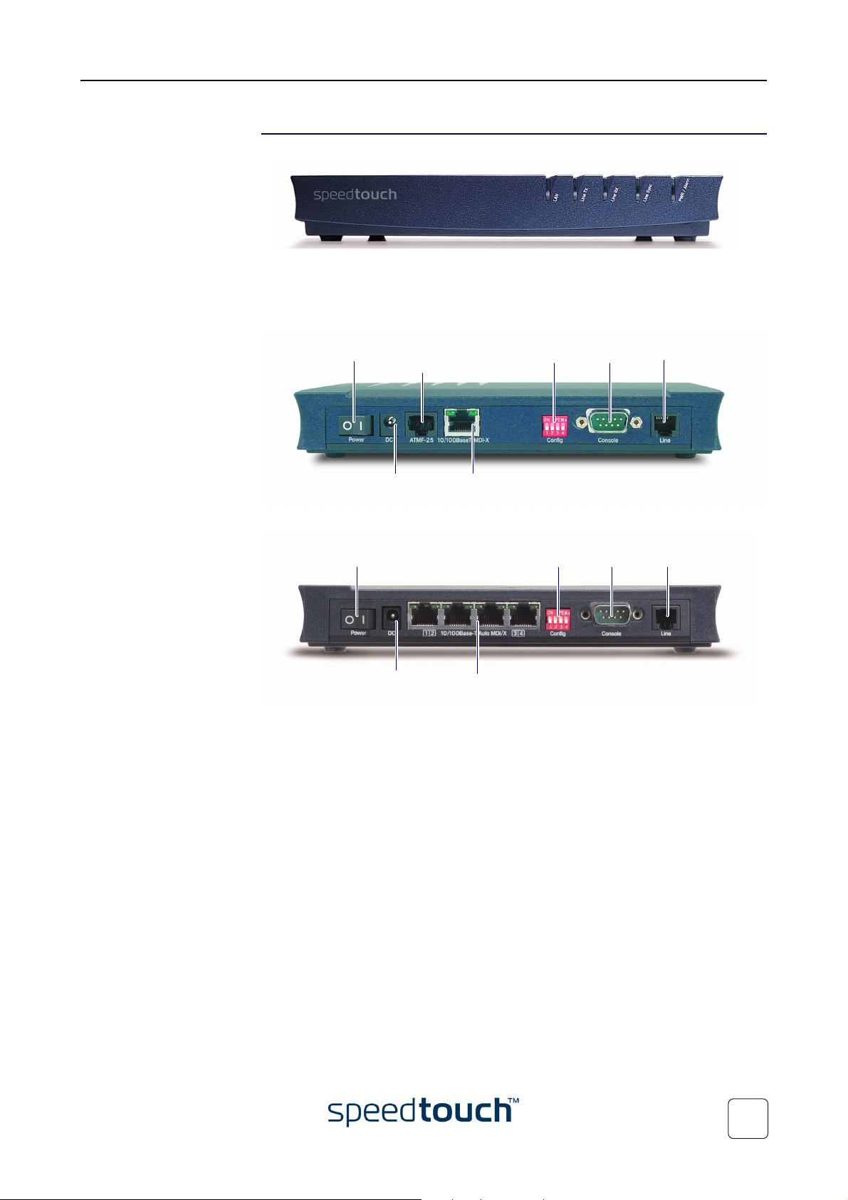
Front and back panel
layout
The SpeedTouch™610 is presented in a slim line housing:
Depending on the SpeedTouch™610 model you purchased, the device can be equipped
with:
• One single 10/100Base-T Half-/Full-duplex MDI-X Ethernet port (optionally with
one 25.6Mb/s ATM-Forum port):
Power Switch Serial Console DSL Line PortDip Switches
25.6Mb/s
ATM-Forum port
Power Socket 10/100Base-T
Ethernet port
• A four port 10/100Base-T Half-/Full-Duplex auto-MDI/MDI-X Ethernet switch:
Power Switch
Serial Console DSL Line PortDip Switches
Power Socket 10/100Base-T Ethernet
switch
E-SIT-CTC-20030306-0004 v2.0
5
Page 10
1 SpeedTouch™610 Installation
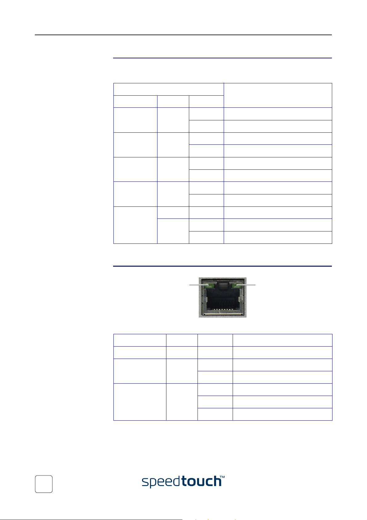
Front panel LEDs The SpeedTouch™610 is equipped with five LEDs on its front panel, indicating the state
of the device during normal operation:
Indicator Description
Name Color State
LAN Green Flashing Ethernet LAN activity
Off No Ethernet LAN activity
Line TX Green Flashing ATM cell transmission on DSL line
Off No transmission activity
Line RX Green Flashing ATM cell reception on DSL line
Off No reception activity
Line Sync Green Flashing Initialization of DSL line
On DSL line synchronized
PWR/Alarm Green On Power on, normal operation
Red Flashing Power on, DIP switch 4 up
On Power on, startup pending
Ethernet port(s) LEDs Each Ethernet port on the rear panel has two LEDs:
10MB/100MB LED
10/100Base -T
Indicator Description
Name Color State
10MB/100MB Green Off 10Base-T Ethernet connectivity
On 100Base-T Ethernet connectivity
Link Integrity/Activity LED
Integrity
Activity
Green Off No connection on this port
On Ethernet link up. No activity
Flashing Activity on this Ethernet port
6
E-SIT-CTC-20030306-0004 v2.0
Page 11

1 SpeedTouch™610 Installation
DSL variants Four DSL variants of the SpeedTouch™610 Business DSL routers exist:
• The SpeedTouch™610:
The ADSL/POTS variant connecting to an analog POTS(*) line.
• The SpeedTouch™610i:
The ADSL/ISDN variant connecting to a digital ISDN(**) line.
• The SpeedTouch™610s:
The SHDSL variant connecting to a dedicated SHDSL(***) line.
• The SpeedTouch™610v:
The SHDSL variant connecting to a dedicated VDSL(****) line.
Use only the SpeedTouch™610 variant which is appropriate for the DSL service delivered to your local premises.
Check at your Service Provider whether your SpeedTouch™610 variant meets the DSL
service requirements.
(*) Plain Old Telephone Service (POTS)
(**) Integrated Services Digital Network (ISDN)
(***) Symmetrical High speed Digital Subscriber Line (SHDSL)
(***) Very high speed Digital Subscriber Line (VDSL)
DSL Port
Service Port pinning
ADSL 3/4
2-wire SHDSL 3/4
VDSL 3/4
4-wire SHDSL 3/4
2/5
DSL service The appropriate DSL service must be available at your local premises:
• ADSL, SHDSL or VDSL service must be enabled on your phone line
• In case of ADSL, both POTS or ISDN and ADSL service are simultaneously avail-
able from the same copper pair. Therefore, you need a central splitter or distributed filters for decoupling ADSL and telephone signals
Always contact your Service Provider for splitter/filter installation!
Public telephone lines carry voltages that can cause electric shock. Only install splitter/
filters yourself if these are qualified for that purpose. Other splitter/filters may only be
installed by qualified service personnel.
E-SIT-CTC-20030306-0004 v2.0
7
Page 12

1 SpeedTouch™610 Installation
1.2 SpeedTouch™610 Wiring
Local network For Ethernet connectivity you need at least:
• A computer with installed Ethernet Network Interface Card (NIC)
• If needed, a hub or switch and the necessary connection cables
Ethernet Cables In the SpeedTouch™610 box, a full wired Cat.5 straight-through RJ45/RJ45 Ethernet
cable, further referred to as LAN cable is included.
You can use LAN cables other than the one provided in the box. However make sure to
use correct connection cables.
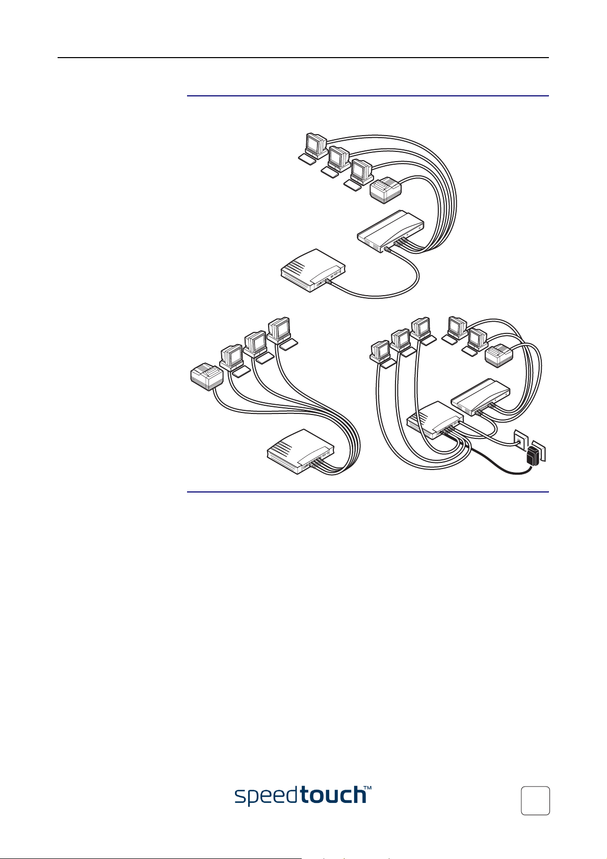
Wiring procedure Proceed as follows:
1 Use the included LAN cable to wire your computer's Ethernet port to (one of)
2 For local networking, repeat step 1 for each computer.
the SpeedTouch™610 Ethernet port(s).
Note If an additional hub or switch is used, please follow the installation
instructions supplied with the hub or switch.
3 Use the included DSL cable to wire the SpeedTouch™610's Line port to your
telephone wall outlet or distributed filter.
4 Plug the power adapter's coaxial jack into the SpeedTouch™610 DC inlet.
Note Always check first whether the included power adapter suits the local
power specifications.
More information on
Ethernet wiring
Single PC wiring Once all connections are made the result should look similar as below:
For more information, see the application note “The SpeedTouch™ and Ethernet
Connectivity”.
8
E-SIT-CTC-20030306-0004 v2.0
Page 13
1 SpeedTouch™610 Installation
LAN wiring Using the SpeedTouch™610 switch (if equipped) and/or an external hub you can
connect multiple PCs to your SpeedTouch™610:
Powering Once all previous steps are completed, you can turn the SpeedTouch™610 on (I) with
E-SIT-CTC-20030306-0004 v2.0
the power switch.
9
Page 14

1 SpeedTouch™610 Installation
1.3 SpeedTouch™610 Configuration Setup
Internet connectivity As soon as the SpeedTouch™610 is installed as described in “1.2 SpeedTouch™610
Wiring” on page 8 the SpeedTouch™610 can be prepared for Internet connectivity.
The configuration of your SpeedTouch™610 can be done semi-automatically via the
SpeedTouch™ Setup configuration files (available on the SpeedTouch™ Setup
CD-ROM), or manually via its web pages.
This section exclusively describes how to configure the SpeedTouch™610 via the Setup
configuration files. For advanced configurations via the SpeedTouch™610 web pages,
check “3 The SpeedTouch™610 Web Interface” on page 27.
What you need from
your SP
SpeedTouch™
configuration options
You must have a user account with an Internet Service Provider (ISP) for Internet
access. For this user account, it will provide you with:
• A user name (logon ID).
• A password.
Other information might be required, depending on the ISP’s specific requirements.
The method for configuring the SpeedTouch™610 via the Setup configuration files
depends on the Operating System (OS) of your computer system.
In case your computer system runs:
• A Microsoft Windows OS
The SpeedTouch™ Setup wizard, included on the SpeedTouch™ Setup CD-ROM,
will automatically guide you through the configuration of both the
SpeedTouch™610 and your PC for setting up the appropriate configuration.
Proceed with “1.3.1 Configuration Setup for Microsoft Windows Operating
Systems” on page 11.
• Another OS, e.g. Mac OS, Unix, Linux, etc.
The SpeedTouch™ Embedded Easy Setup wizard, accessible from the SpeedTouch™ web pages, will automatically guide you through the configuration of the
SpeedTouch™610.
10
If needed, additional configuration of your computer(s) must be done manually.
Proceed with “1.3.2 Configuration Setup for other Operating Systems” on
page 17.
E-SIT-CTC-20030306-0004 v2.0
Page 15

1 SpeedTouch™610 Installation
1.3.1 Configuration Setup for Microsoft Windows Operating Systems
Microsoft Windows One of the following operating systems must be installed on your PC(s):
• Windows 98
• Windows 98SE
• Windows ME
• Windows NT4.0 SP6
• Windows 2000
• Windows XP
TCP/IP Make sure that TCP/IP (*) is installed on your PC(s).
(*) Transmission Control Protocol (TCP) / Internet Protocol (IP)
The SpeedTouch™
Setup Wizard
The SpeedTouch™ Setup wizard procedure consists of two major parts:
• The detection procedure
• The configuration procedure
E-SIT-CTC-20030306-0004 v2.0
11
Page 16
1 SpeedTouch™610 Installation
The detection
procedure
The detection procedure proceeds as follows:
1 Insert the SpeedTouch™ Setup CD-ROM in your PC's CD-ROM drive. The
SpeedTouch™ CD Browser will start automatically.
Note If the SpeedTouch™ CD Browser window does not appear automati-
cally, open a Run window via Start > Run from the Start menu and
enter following path: D:\Menu.exe, where D is the drive letter of your
CD-ROM drive.
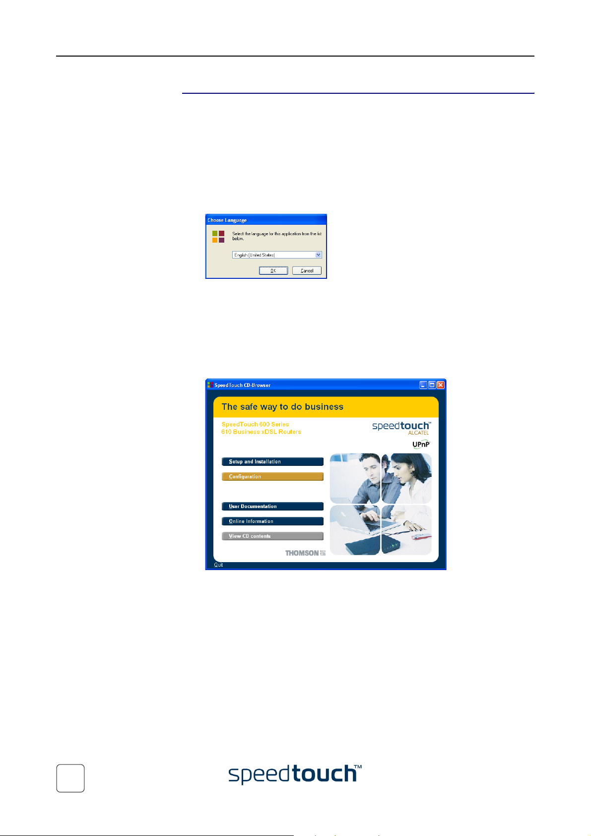
2 The Choose Language window prompts you to select a language:
Select the language of your choice and click OK.
Note The selected language will also be used as default language in the
SpeedTouch™ web pages.
See “ Language” on page 56 for more information on how to change
the web page language.
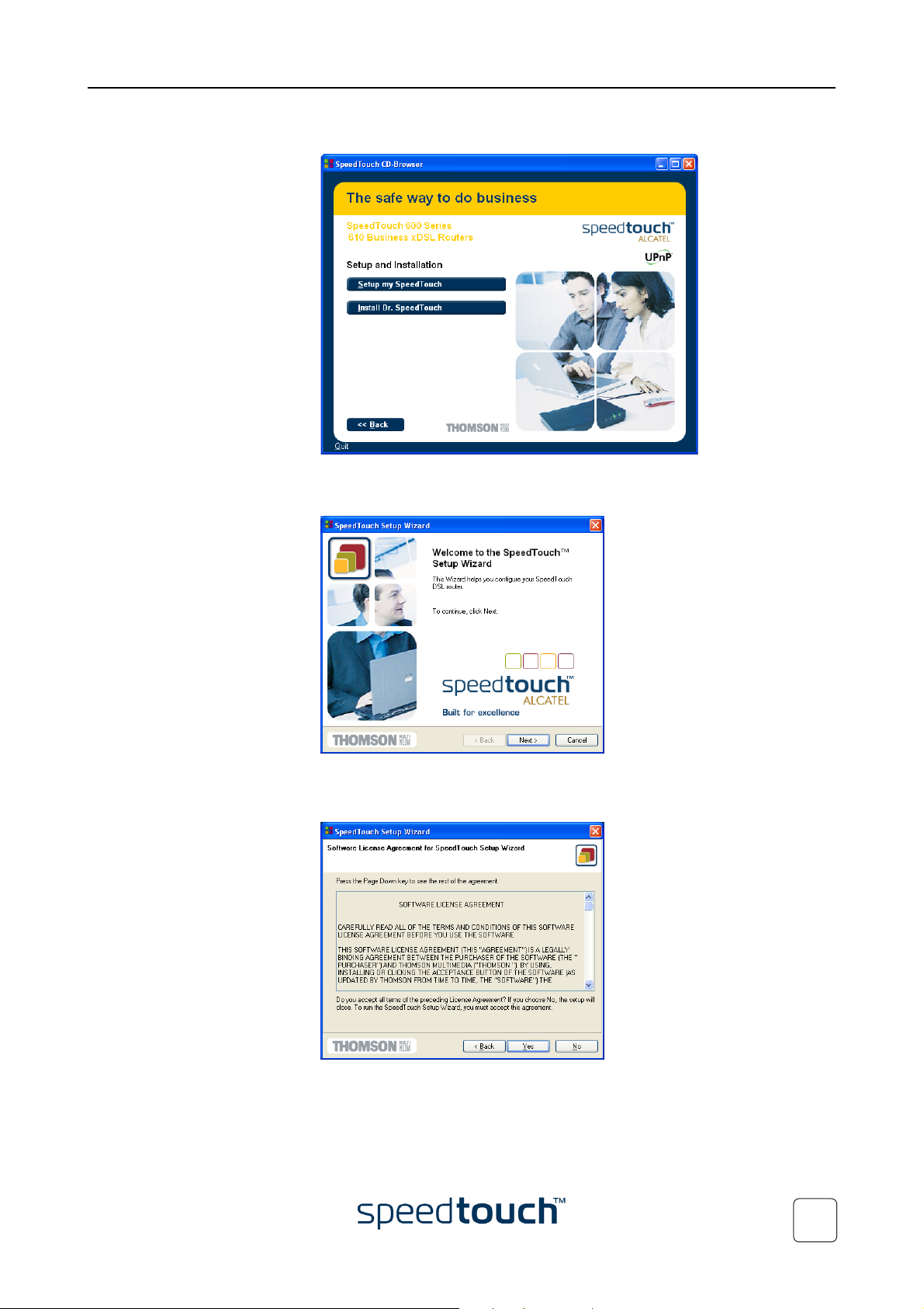
3 The SpeedTouch™ Menu appears:
12
Click Setup and Installation.
E-SIT-CTC-20030306-0004 v2.0
Page 17
1 SpeedTouch™610 Installation
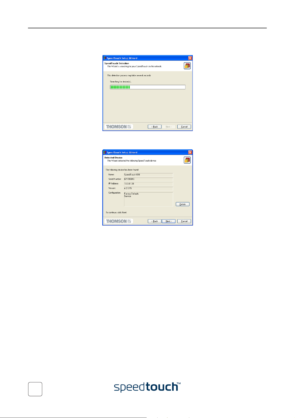
4 The Setup and Installation window appears:
To start the SpeedTouch™ Setup wizard, click Setup my SpeedTouch™.
5 The Welcome to the SpeedTouch™ Setup Wizard window appears:
E-SIT-CTC-20030306-0004 v2.0
Click Next to proceed.
6 The Software License Agreement window appears:
You must accept before continuing. Therefor click Yes to accept.
Note If you have already accepted this License Agreement in a previous
configuration setup, this window will not be shown.
13
Page 18
1 SpeedTouch™610 Installation
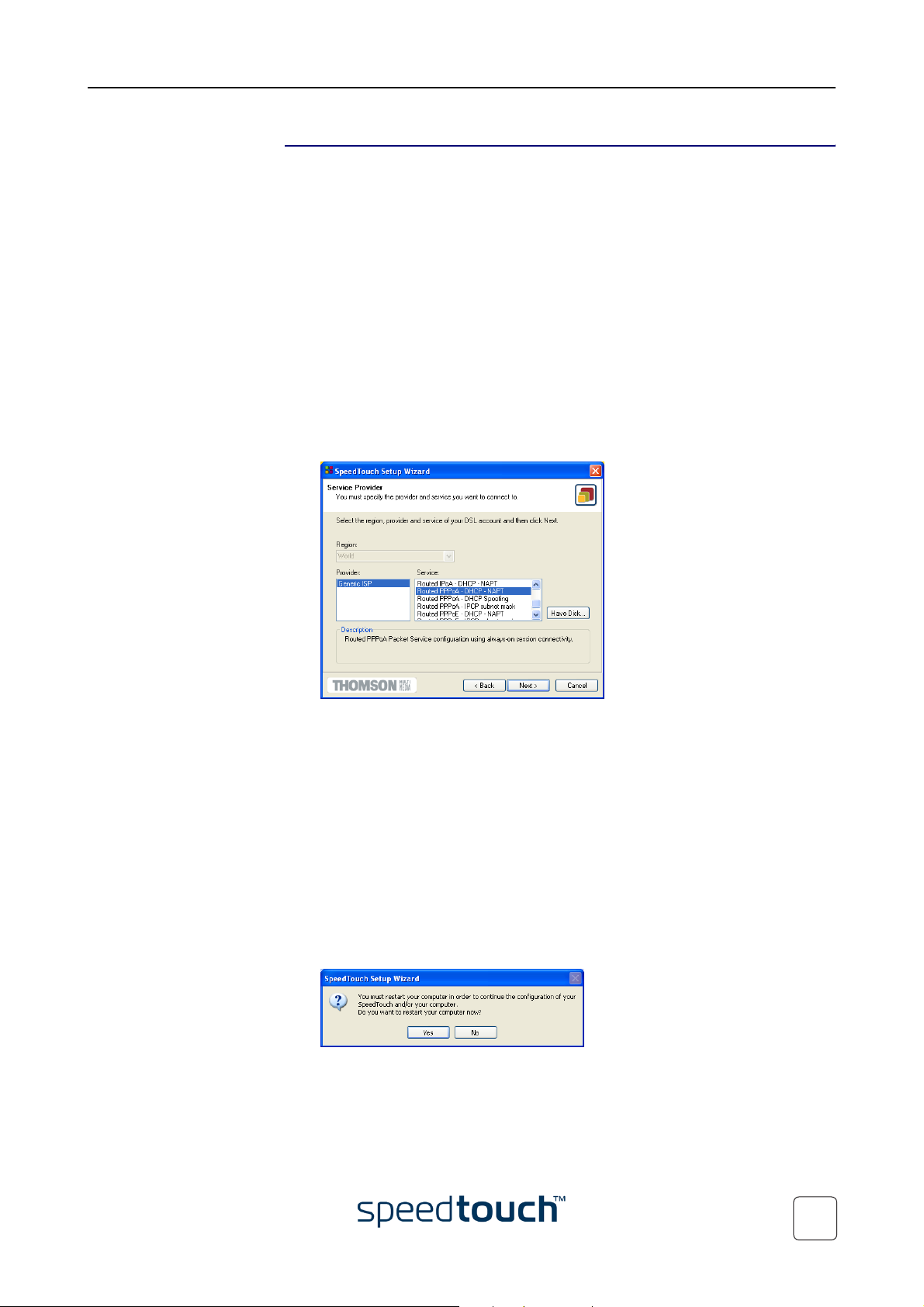
7 The Setup wizard will continue to search for the SpeedTouch™610 on the net-
work. The following window shows the detection progress:
8 The setup wizard should find your SpeedTouch™610 device on the local network.
This is indicated by following window:
In case more than one SpeedTouch™ device is found, a listing is provided from
which you can select your SpeedTouch™610.
Note If the wizard does not find a SpeedTouch™610 on the network, an
error window appears. In this case check:
• Whether the SpeedTouch™610 is turned on and fully initialized.
• Whether your PC is correctly connected to the Speed-
Touch™610.
• Whether no dedicated firewall device or a router is placed
between your PC and the SpeedTouch™610 and whether no
personal firewall software is running on your PC.
• Whether TCP/IP is correctly installed on your PC, and whether
your PC is configured with a valid IP address as DHCP client, or
via automatic IP configuration.
To repeat search for the SpeedTouch™610, click Back and proceed
with step 7 of this procedure.
9 To continue with the configuration of your SpeedTouch™610 and your PC, pro-
ceed with the configuration procedure described below.
14
E-SIT-CTC-20030306-0004 v2.0
Page 19
1 SpeedTouch™610 Installation
The configuration
procedure
The configuration procedure proceeds as follows:
1 As soon the wizard detected your SpeedTouch™610, some device details are
shown. In case multiple SpeedTouch™ devices reside on your local LAN, a listing
of devices is shown from which you can select the appropriate one.
Click Next to proceed.
Note If the SpeedTouch™610 has been configured before:
• It may be protected by a system password. Before you are able to
view the device details or continue with the configuration this
password has to be entered.
• You will be asked to choose between reconfiguring your Speed-
Touch™610 or changing your Local Area Network configuration.
Select the Reconfigure the SpeedTouch™ option and click Next.
2 The following window invites you to select the appropriate connection profile for
your Internet connectivity:
Select the connection profile and click Next to continue.
Note In case the Service Provider included a separate disk with a dedicated
connection profile, click Have Disk to browse to the location of the
appropriate connection profile file.
3 Subsequent screens will guide you through the configuration setup of both the
SpeedTouch™610 and/or your PC. Follow the instructions and enter the required
information where needed.
The needed information will depend on the selected connection profile and
should be provided by your Service Provider.
Click Next whenever requested.
4 After configuration, the SpeedTouch™610 will restart. In some cases your PC
must be restarted as well for the changes to take effect:
E-SIT-CTC-20030306-0004 v2.0
15
Page 20
1 SpeedTouch™610 Installation
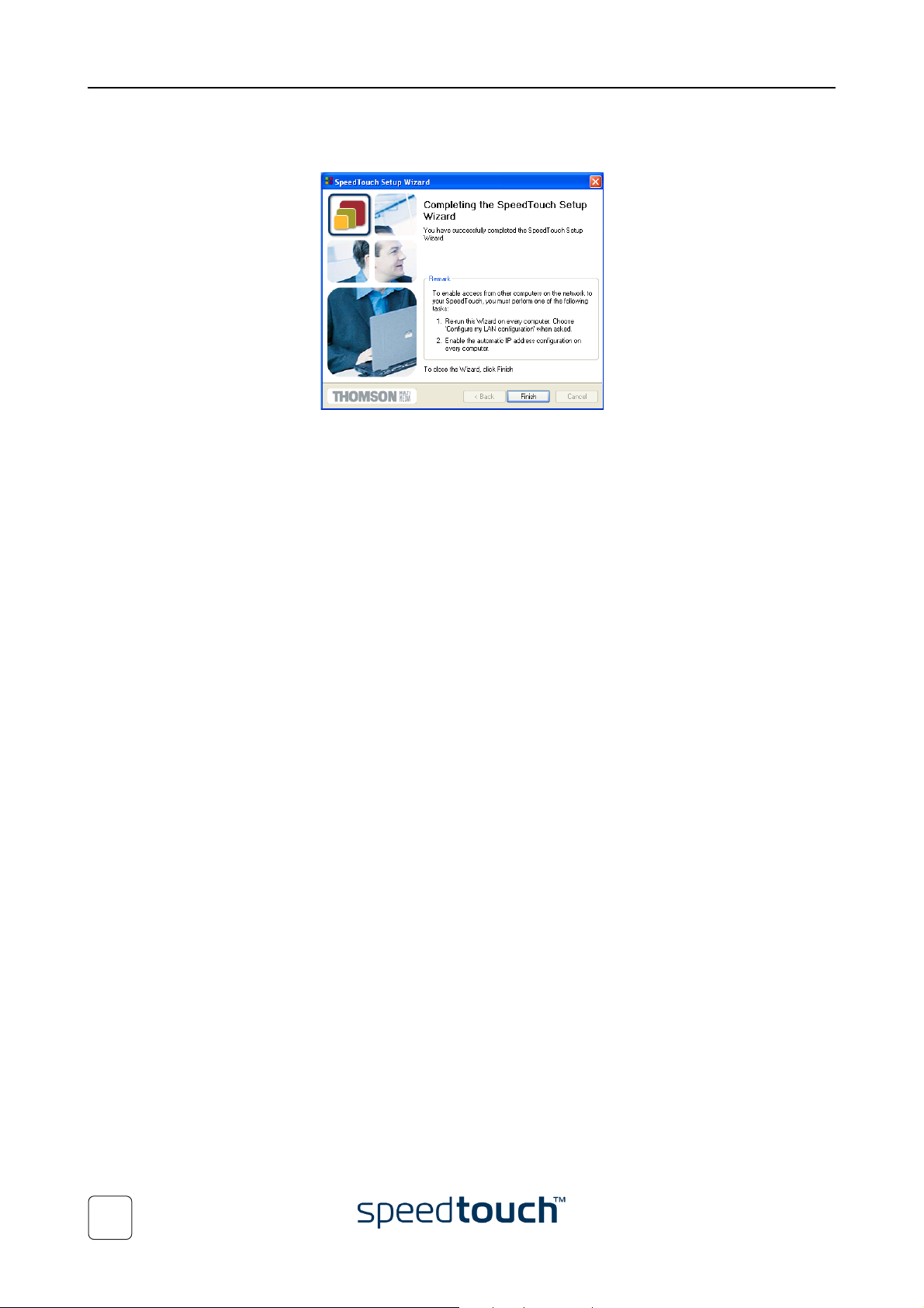
5 After restarting your PC, the SpeedTouch™ Setup wizard will appear again to
announce that the configuration has been successful:
Click Finish to close the wizard.
Most configuration profiles will enable SpeedTouch™610’s DHCP server - and a PC’s
Ethernet port is configured as DHCP client by default. Therefore, in most cases, no
additional configuration of your PCs must be done if you want to enable multiple PCs
on your local network for accessing the Internet via the SpeedTouch™610.
To make sure that all PCs are configured as expected (DHCP or fixed IP addresses) you
can re-run the SpeedTouch™ Setup wizard on every PC and select the Change the LAN
configuration option.
For fixed IP configurations, or other advanced settings, please follow the instructions
provided by your ISP or network administrator.
16
E-SIT-CTC-20030306-0004 v2.0
Page 21

1 SpeedTouch™610 Installation
1.3.2 Configuration Setup for other Operating Systems
Supported Operating
Systems
TCP/IP Ensure that your operating system has a valid TCP/IP configuration.
Procedure The configuration setup proceeds as follows:
As the SpeedTouch™610 is OS-independent, this configuration setup can be used by
any computer system.
Note The following procedure may equally be used on MS Windows OSs.
Configure your computer with a static Net10 private IP address, e.g. 10.0.0.1, 10.0.0.2,
etc. Ensure, however, that you do NOT use the 10.0.0.138 IP address as this is the
default IP address of the SpeedTouch™610.
To ensure that IP connectivity exists, you can ping the SpeedTouch™610.
1 Open a web browser and browse to the SpeedTouch™ IP address e.g. 10.0.0.138.
See “3 The SpeedTouch™610 Web Interface” on page 27 for more information.
Note If you can not access the SpeedTouch™610 web pages, it is recom-
mended to reset the device. See “5 Troubleshooting” on page 69.
2 As a result the SpeedTouch™ System Info web page appears.
Expand the Advanced Topics and click Easy Setup.
Note If the SpeedTouch™ is in factory defaults, the Easy Setup wizard will
appear automatically.
3 The Welcome to the SpeedTouch™ Setup Wizard window appears:
E-SIT-CTC-20030306-0004 v2.0
Click Next to continue.
17
Page 22
1 SpeedTouch™610 Installation
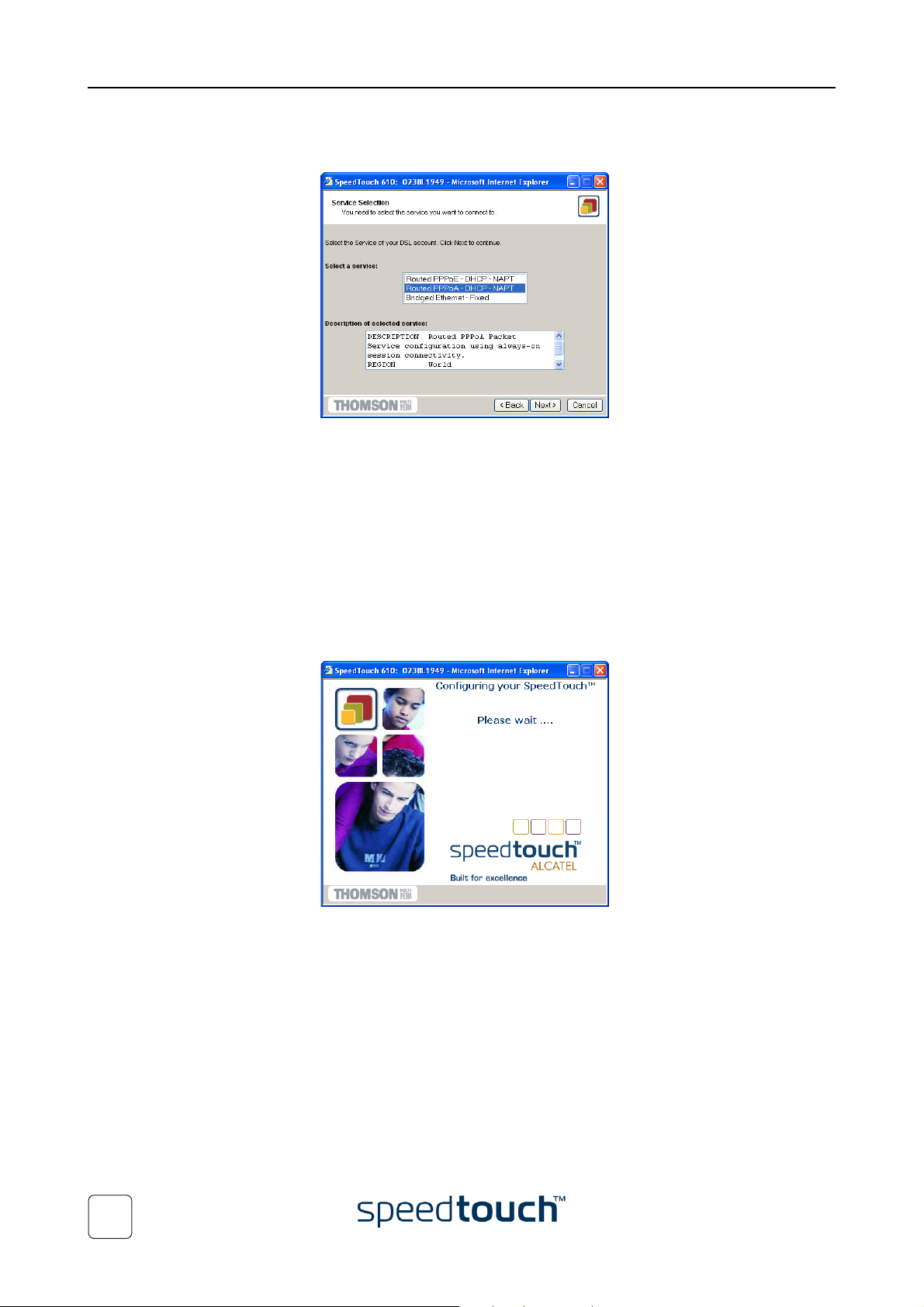
4 The following window invites you to select the appropriate connection profile for
your internet connectivity:
In the Service list, click the connection profile of your choice.
Note You can add services to the Services list by uploading templates.
See “ Templates” on page 56 for more information on uploading
templates.
5 Subsequent screens guide you through the configuration setup of both your
SpeedTouch™ and/or your PC. Follow the instructions and enter the required
information where needed.
The needed information will depend on the selected connection profile and
should be provided by your Service Provider.
Click Next whenever requested.
6 In a final step all configurations are applied to the SpeedTouch™610:
18
E-SIT-CTC-20030306-0004 v2.0
Page 23
1 SpeedTouch™610 Installation
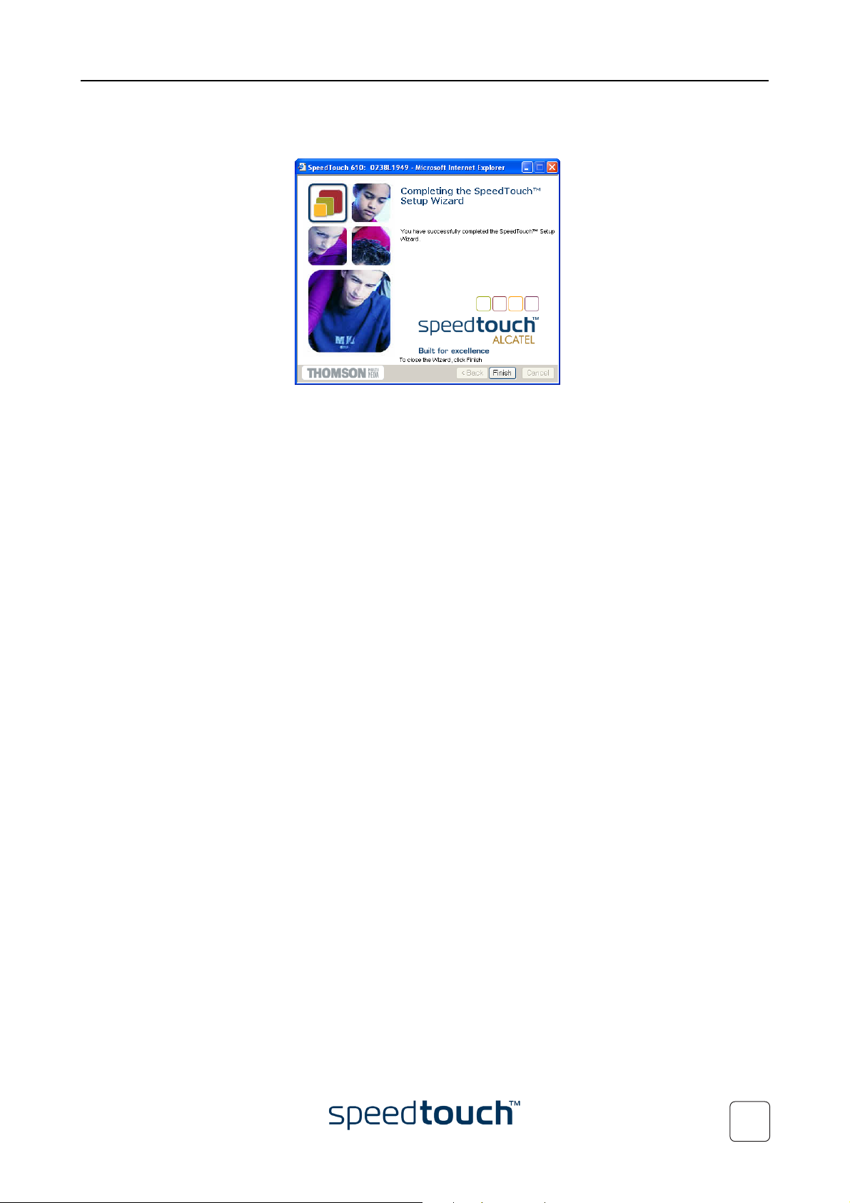
7 The SpeedTouch™ Setup Wizard appears again to announce that the configura-
tion has been successfully completed:
Click Finish to close the wizard.
8 After the configuration is applied on the SpeedTouch™ some additional configura-
tion of your computer system may be necessary.
Note The required settings for your computer should be provided by your
Service Provider, if applicable.
9 To check whether the new configuration was successful, you can browse to the
SpeedTouch™ and check its current status.
Note By running the Easy Setup wizard the SpeedTouch™’s IP configuration
may have been changed. To browse the SpeedTouch™ web pages,
make sure you use its new IP address, if applicable.
E-SIT-CTC-20030306-0004 v2.0
19
Page 24
1 SpeedTouch™610 Installation
1.4 Dr. SpeedTouch™ Installation
Introduction The Dr. SpeedTouch™ application allows you to diagnose and troubleshoot your
SpeedTouch™610.
With the Dr. SpeedTouch™ application you can do the following:
• View the status and performance of the SpeedTouch™ device
• Run a Diagnostics program to locate a connectivity problem
• Run a Troubleshooter to help you solve a connectivity problem.
Supported Operating
Systems
Installation procedure The installation procedure proceeds as follows:
Installing and using Dr. SpeedTouch™ is only supported for following Microsoft
Windows Operating Systems:
• Windows 98
• Windows 98SE
• Windows ME
• Windows NT4.0 SP6
• Windows 2000
• Windows XP
1 Insert the SpeedTouch™ Setup CD-ROM in your PC's CD-ROM drive. The
SpeedTouch™ CD Browser will start automatically. Choose your language and
browse to Setup and Installation > Install Dr. SpeedTouch™.
Note If the SpeedTouch™ CD Browser window does not appear automati-
cally, open a Run window via Start > Run from the Start menu and
enter the following path: D:\Menu.exe, where D stands for the drive
letter of your CD-ROM drive.
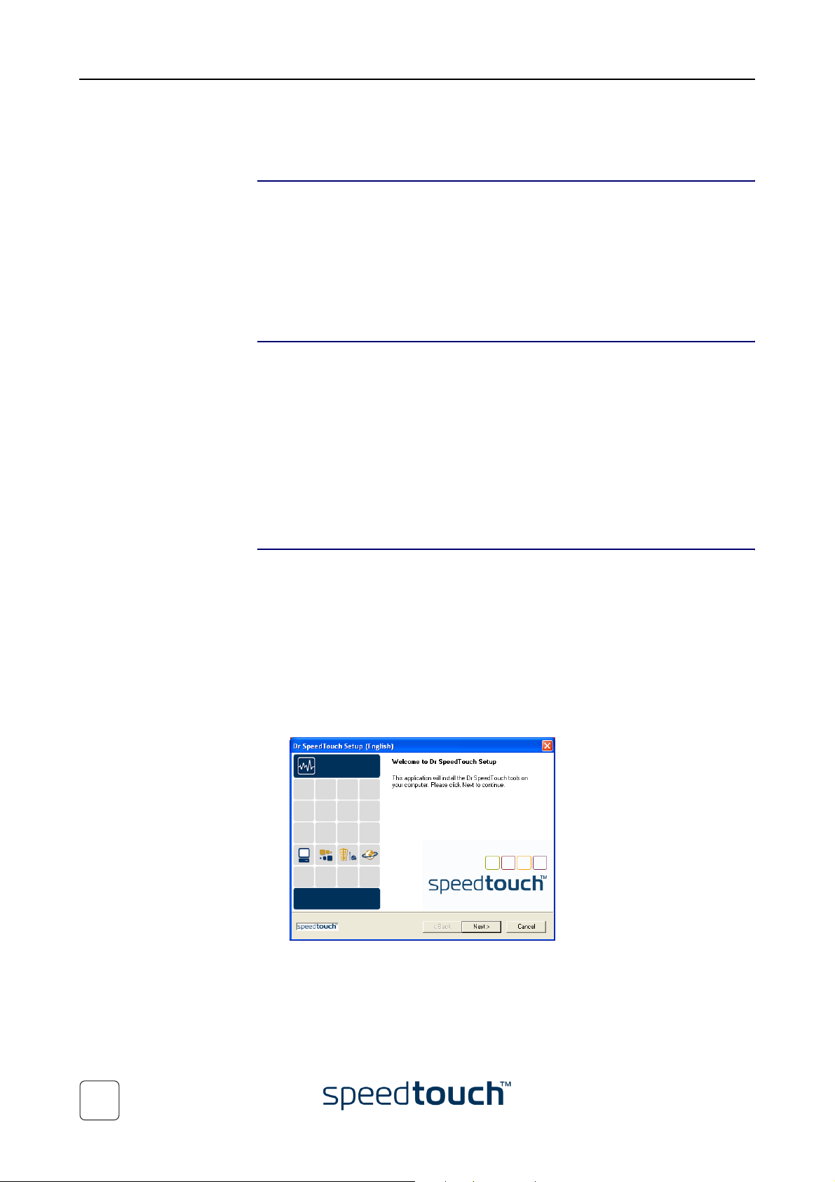
2 The Dr. SpeedTouch™ Setup wizard appears:
20
Click Next to continue.
3 Subsequent screens will guide you through the installation. Follow the provided
instructions and click next whenever requested.
4 After installation, Dr. SpeedTouch™ is started automatically.
E-SIT-CTC-20030306-0004 v2.0
Page 25

1 SpeedTouch™610 Installation
Using Dr. SpeedTouch™ By default Dr. SpeedTouch™ is started automatically at boot of your system and runs in
the background, i.e. minimized in the status area.
To pop up Dr. SpeedTouch™:
1 Double-click in the status area.
2 Dr. SpeedTouch™ searches your network for SpeedTouch™ devices. If more than
one device is found, a list of available devices will be provided. If this is the case,
select the SpeedTouch™ of your choice and click OK.
3 The Dr. SpeedTouch™ window appears:
Dr. SpeedTouch™
features
Dr. SpeedTouch™ allows you to:
• View SpeedTouch™610 device information and status:
• View activity between your computer, the SpeedTouch™610 and the Internet:
E-SIT-CTC-20030306-0004 v2.0
21
Page 26

1 SpeedTouch™610 Installation
• Monitor the downstream and upstream performance. of your DSL connection:
• Test and troubleshoot the connectivity of your computer and the Speed-
Touch™610 device to your ISP and the Internet via the Diagnostics wizard.
22
Note For more information on Dr. SpeedTouch™ please click Help in the applica-
tion or press F1 context sensitive help.
E-SIT-CTC-20030306-0004 v2.0
Page 27

2 SpeedTouch™610 Internet Connectivity
2 SpeedTouch™610 Internet Connectivity
Introduction This chapter provides information on how to access the Internet and how to configure
your SpeedTouch™ according to your preferences.
Surfing the Internet As soon as the SpeedTouch™610 and the computer(s) have been configured as outlined
in “1.3 SpeedTouch™610 Configuration Setup” on page 10, you can connect to the
Internet.
Connection Services and Packet Services
Direct Access In case the SpeedTouch™610 is configured for direct access (always-on or dial-on-
Dial-in access In case the SpeedTouch™610 is configured for dial-in access, you can manually start and
The SpeedTouch™610 supports various scenarios to establish end-to-end connectivity
with the BroadBand Remote Access Server (BBRAS) and the Internet.
For more information, see the application note “SpeedTouch™ Connection and Packet
Services”.
The scenario to use depends on the configuration profile/file you used to configure the
SpeedTouch™610 and the Service Provider's requirements.
demand) you can immediately surf the internet.
Note In some cases however, e.g. in case of Transparent Bridging, the remote
organization still might ask for a user name and password on an Internet
welcome page for authentication.
terminate the PPP session. On the following pages, we explain how to start/terminate a
PPP session via:
• UPnP.
See “2.1.1 Internet Sessions via Windows XP’s UPnP” on page 25
• The SpeedTouch™610 web pages.
See “2.1.2 Internet Sessions via the SpeedTouch™ Web Pages (all OSs)” on
page 26.
E-SIT-CTC-20030306-0004 v2.0
23
Page 28

2 SpeedTouch™610 Internet Connectivity
2.1 Connect to the Internet via SpeedTouch™’s embedded PPP Client
Introduction The SpeedTouch™ supports both two most popular connection methods: Routed PPP
over ATM (PPPoA) and PPP over Ethernet (PPPoE).
The connection method to use depends on the preferences of your ISP, hence the
connection profile you must apply to the SpeedTouch™ via the SpeedTouch™ Setup
wizard or its embedded Easy Setup wizard.
Note To use the embedded Routed PPPoA (PPPoE) dial-in client, the
SpeedTouch™ needs to be configured for Routed PPPoA (PPPoE) via the
SpeedTouch™ Setup wizard or the embedded Easy Setup wizard.
To use a host PPPoE dial-in client, the SpeedTouch™ needs to be configured
for Bridged Ethernet or Routed PPPoE (with PPPoE Relay) via the
SpeedTouch™ Setup wizard or embedded Easy Setup wizard.
24
E-SIT-CTC-20030306-0004 v2.0
Page 29

2 SpeedTouch™610 Internet Connectivity
2.1.1 Internet Sessions via Windows XP’s UPnP
Starting an Internet
session via Windows
XP’s UPnP
To connect to the internet via Windows XP’s Internet Connection icon proceed as
follows:
1 Click Control Panel on the Start menu.
2 The Control Panel window appears. Double-click Network Connections.
3 The Network Connections window appears:
Double-click the Internet Connection icon.
4 Your computer connects to the Internet.
Terminating an Internet
Session session via
Windows XP’s UPnP
To close an active Internet session:
1 Click Control Panel on the Start menu.
2 The Control Panel window appears. Double-click Network Connections.
3 The Network Connections window appears. Double-click the Internet Connec-
tion icon.
4 The Internet Connection Status window appears:
Click Disconnect to close the session.
5 Your computer terminates the connection.
E-SIT-CTC-20030306-0004 v2.0
25
Page 30

2 SpeedTouch™610 Internet Connectivity
2.1.2 Internet Sessions via the SpeedTouch™ Web Pages (all OSs)
Starting a PPP session To open a Routed PPP connection proceed as follows:
1 Open a web browser on your computer and browse to the SpeedTouch™610
web pages:
Terminating an active
PPP session
By default the SpeedTouch™610 offers you the System Information page.
2 In the Quick menu, click Connections to open the Connections page which
enables you to establish dial-in connections.
3 Click next to the connection entry you want to establish a connection with. As
a result the entry will be highlighted.
4 Enter your user name and password in the appropriate fields. If you want the
SpeedTouch™610 to remember your credentials, select Save this password.
5 Click Connect.
While the SpeedTouch™610 tries to start the session 'trying' appears in the State
column of the entry. Once the session is started successfully the field displays ‘up’.
From then on you are online and you can start your application or browse the
Internet.
To close an active Routed PPP connection:
1 Make sure you have access to the SpeedTouch™610 web pages.
2 On the Connections page, click next to the connection entry you want to close
the connection for.
3 Click Disconnect.
As a result the session state of the entry will change to ‘down’, i.e. it becomes idle.
26
E-SIT-CTC-20030306-0004 v2.0
Page 31

3 The SpeedTouch™610 Web Interface
3 The SpeedTouch™610 Web Interface
Introduction The SpeedTouch™610 comes with integrated local configuration capabilities.
The local configuration via the SpeedTouch™610 web interface, is based on the HTTP
server/web browser concept.
It allows configuration of your SpeedTouch™610 via a Web browser through HTML
pages from any local computer attached to the Ethernet interface(s).
Preconditions Prior to access the SpeedTouch™610 web pages make sure that either:
• Your Web browser is not using a proxy server.
• The SpeedTouch™610 IP address is not submitted to a proxy server.
For more information on how to disable your web browser's proxying, please consult
your web browser's user’s guide.
Use of the
SpeedTouch™ web
interface
In most cases the SpeedTouch™610 is correctly configured for your Internet connectivity via the appropriate configuration profile/file and no further configuration on the
web interface is needed.
Only for using the advanced SpeedTouch™610 features, access to the web pages is
required.
This chapter aims to give a brief overview of the SpeedTouch™610 web pages and their
respective functionality.
For more profound Information, see the relevant application notes.
E-SIT-CTC-20030306-0004 v2.0
27
Page 32

3 The SpeedTouch™610 Web Interface
3.1 General Principles
Access to the
SpeedTouch™610 web
interface
Access to the
SpeedTouch™610 web
interface via UPnP
To access the SpeedTouch™ web pages:
1 Start the web browser on your computer.
2 Browse to the SpeedTouch™610 at the SpeedTouch™610’s IP address (in most
cases 10.0.0.138).
3 If a system password was set, an authentication window will be displayed.
Enter user name and system password in the appropriate fields.
If your computer is Universal Plug and Play (UPnP) enabled, you can access the SpeedTouch™ web pages as follows:
1 Double-click My Network Places on your desktop.
2 The following window appears:
Double-click the SpeedTouch™610 icon.
3 If a system password was set, an authentication window will be displayed.
Enter user name and system password in the appropriate fields.
28
E-SIT-CTC-20030306-0004 v2.0
Page 33

3 The SpeedTouch™610 Web Interface
Result As a result the System Information page appears:
From now on the SpeedTouch™610 acts as a web server sending HTML pages/forms at
your request. You can fill out these pages/forms and submit them to the SpeedTouch™610. The latter scans the pages and performs the appropriate configurations.
Topic menu and links On the left of each of the SpeedTouch™610 web pages a topics menu is provided. This
menu navigates you via links through all configurational aspects of the SpeedTouch™610.
For your convenience the links are sorted in six expandable topics menus: Quick, IP
Router, Connections, LAN Services, System Config, and Advanced. Each of these offers
you a set of specific links, leading you to a configuration aspect of the SpeedTouch™610.
The following table lists all Quick Tasks Links:
Click ... To ...
Easy Setup Configure SpeedTouch™610.
System Information View the current configuration profile.
View current ADSL line status.
Connections Establish dial-in PPPoA and/or PPPoE connections.
Diagnostics View the SpeedTouch™610 diagnostics.
E-SIT-CTC-20030306-0004 v2.0
Syslog View/configure Syslog services.
29
Page 34

3 The SpeedTouch™610 Web Interface
The following table lists all IP Router Tasks Links:
Click ... To ...
IP Addresses View/configure the SpeedTouch™610 IP interfaces.
IP Routing View/configure the SpeedTouch™610 IP router.
RIP View/configure RIP services.
NAPT View/configure static NAPT services.
IPSEC Policy View/configure IPSec based VPN services.
IPSEC Certificates View/configure the certificate configuration.
The following table lists all Connection Tasks Links:
View/configure multi-NAT entries.
Define a Default local server for inbound connectivity.
Configure UPnP.
Click ... To ...
Phonebook View/configure connection service entries.
Routed Ethernet Configure Routed Ethernet.
Routed PPPoE Configure Routed PPPoE.
Routed PPPoA Configure Routed PPPoA.
Routed IPoA Configure Routed IPoA.
Classical IP Configure Routed Classical IPoA.
Bridged Ethernet Configure Bridged Ethernet (for Bridged PPPoE).
Relayed PPPoA View current Relayed PPPoA connections.
The following table lists all LAN Services Tasks Links:
Click ... To ...
DHCP View/configure DHCP services.
DNS View/configure DNS services.
SIP View/configure SIP services.
30
E-SIT-CTC-20030306-0004 v2.0
Page 35

3 The SpeedTouch™610 Web Interface
The following table lists all System Config Tasks Links:
Click ... To ...
System Password Set a system password.
Upgrade Manage software and configuration.
Add-On Manage software keys.
SNTP View/configure SNTP services.
Syslog View/configure Syslog services.
The following table lists all Advanced Tasks Links:
Click ... To ...
CLI Open the web based Command Line Interface.
Te m p l a t e s View/upload templates.
Language Configure the SpeedTouch™610 web page language.
Save All The Save All link on the tasks menu allows you to save the SpeedTouch™610 settings to
memory.
It is advised to back-up your saved configuration on a regular basis. This can be done via
the Upgrade link in the System Config Tasks Links.
Help The Help link in the topics menu header allows you to browse the SpeedTouch™610
online Help.
For more information on a specific topic you can click the context-related Help links
located at the topic’s web pages.
E-SIT-CTC-20030306-0004 v2.0
31
Page 36

3 The SpeedTouch™610 Web Interface
3.2 Quick Tasks Links
Easy Setup Click this link to start the SpeedTouch™ Easy Setup wizard.
See “1.3.2 Configuration Setup for other Operating Systems” on page 17 for more
information.
System Information Click this link to display the System Information page. This page is also the Speed-
Touch™610 home page.
The System Information page consists of four sections:
• Click the Diagnostics tab to view the results of the System Self Test, LAN Connec-
tivity and DSL synchronization test:
• Click the Service Info tab to view the current physical status of the ADSL line:
The DSL statistics allow you to view:
• Line Status: this shows wether the DSL link is synchronized (Enabled) or not
(Initializing).
• Bandwidth Up/Down: the maximum available bandwidth of the DSL link in
both up- and downstream direction.
• Uptime: The duration of the current Enabled Line Status.
• kBytes Tx/Rx: the amount of kilobytes (kBytes) sent (Tx) and received (Rx)
since the establishment of the DSL link.
32
E-SIT-CTC-20030306-0004 v2.0
Page 37

3 The SpeedTouch™610 Web Interface
• Click the configuration tab to view which configuration profile/file is currently
loaded, including information for which Region and ISP this configuration applies:
• Click the System tab to view some important system information of the Speed-
Touch™:
Connections Click this link to view the Connections page.
This page allows you to establish dial-in connections, if applicable:
See “2.1.2 Internet Sessions via the SpeedTouch™ Web Pages (all OSs)” on page 26 for
more information on how to use the Connections table.
For more information on the configuration and use of PPP connections, see the application notes “The SpeedTouch™ Routed PPPoA Packet Service” and “The SpeedTouch™
Routed PPPoE Packet Service”.
E-SIT-CTC-20030306-0004 v2.0
33
Page 38

3 The SpeedTouch™610 Web Interface
Diagnostics Click this link to display the Diagnostics page.
This page consists of three expandable sections:
• Expand the System section to view some important system information:
• Expand the Wan section. To view the current DSL state and connection informa-
tion, expand the DSL and connections sections:
34
Click to perform an IP connectivity test.
• Expand the Lan section to view the LAN configuration:
E-SIT-CTC-20030306-0004 v2.0
Page 39

Syslog Click this link to display the Syslog page.
This page allows you to:
• View the syslog messages generated by the SpeedTouch™610:
This page refreshes every 30 seconds. Via the CLI you can configure additional
syslog events to be notified by syslog messages in addition to the standard set of
syslog events.
3 The SpeedTouch™610 Web Interface
• Configure a computer IP address to send syslog messages to. This allows basic
remote monitoring of the SpeedTouch™610:
For more information on Syslog, see the application notes “SpeedTouch™610 Operation and Maintenance” and “SpeedTouch™610 Remote Management”.
E-SIT-CTC-20030306-0004 v2.0
35
Page 40

3 The SpeedTouch™610 Web Interface
3.3 IP Router Tasks Links
IP Addresses Click this link to display the IP Addresses page.
This page allows you to view or add/delete specific IP address entries for the SpeedTouch™610 interfaces:
When adding an IP address, all essential IP routes will be automatically be added to the
SpeedTouch™610 IP routing table. The eth0 interface allows you to assign an IP address
to the SpeedTouch™ Ethernet interface.
IP Routing Click this link to display the IP Routing page.
This page allows you to view or add/delete static IP routes for SpeedTouch™610's IP
router:
Routing can be useful in the case of subnetting your local network.
36
E-SIT-CTC-20030306-0004 v2.0
Page 41

3 The SpeedTouch™610 Web Interface
RIP Click this link to display the Routing Information Protocol (RIP) page.
This page allows you to:
• View or configure the SpeedTouch™610's general RIP configuration:
Via the RIP Settings tab you can enable/disable the master RIP daemon and specify
which RIP version should be used. Additionally you can set the default metric and
some RIP timer settings.
• View or configure the RIP configuration per interface:
Per interface you can:
• Override the master RIP status (enable/disable)
• Override the master RIP version, separately for receiving and sending RIP
messages
• Specify whether authorization is needed or not, and if so the required autho-
rization string
• Specify whether the scope of RIP on this interface should be narrowed to
the applicable IP range.
• Define one or more RIP neighbors in case multicast messages can not be sent or
received among the network
E-SIT-CTC-20030306-0004 v2.0
Do not forget to save your changes to persistent memory by clicking Save All.
37
Page 42

3 The SpeedTouch™610 Web Interface
NAPT Click this link to display the Network Address and Port Translation (NAPT) page.
This page allows you to:
• View or add/delete specific static NAPT entries:
You can add static NAPT entries by
1 Click New.
2 Specify the outside address and inside address for the entry as well as the
protocol and port on which the entry applies.
Note If the NAPT entry is applied to a connection’s dynamically
assigned local peer IP address, you should specify 0.0.0.0 as the
outside address.
3 Click Apply to add the entry to the table.
You can also add static NAPT entries semi-automatically using the SpeedTouch™
NAPT Manager. For more information on NAPT Manager, see “3.8 SpeedTouch™
NAPT Manager” on page 57.
• View or add/delete Multi-NAT Entries:
Multi-NAT is also commonly known as Basic NAT (IETF). To add Multi-NAT
Entries proceed as follows:
1 Click New.
2 Specify the inside address and put the desired range between brackets e.g.
10.0.0.[1-10]. Specify the outside address and interface.
3 Click Apply.
38
E-SIT-CTC-20030306-0004 v2.0
Page 43

3 The SpeedTouch™610 Web Interface
• Define a default server:
By specifying a default server IP address (e.g. 10.0.0.3 as depicted above), all
incoming connections that don’t match a specifically configured static NAPT entry
will be forwarded to the device with this IP address. In most cases this setting
should be adequate for most server applications and eliminates the need for
specific static NAPT entries.
• Configure Universal Plug and Play (UPnP):
The three UPnP configurations are:
• Full
The SpeedTouch™ is UPnP enabled, all local hosts are able to detect the
SpeedTouch™. Any local host is able to create port mappings for any local
device.
• Secure
The SpeedTouch™ is UPnP enabled, all local hosts are able to detect the
SpeedTouch™. A local host is allowed to make port mappings for its own,
i.e. a local host is not allowed to create port mappings for other local
devices.
• Off
The SpeedTouch™ is UPnP disabled, none of the local hosts is able to detect
the SpeedTouch™. Via UPnP no port mappings can be created.
For more information, see the application notes “The SpeedTouch™ and Network
Address Translation” and “The SpeedTouch™ and Universal Plug and Play”.
E-SIT-CTC-20030306-0004 v2.0
39
Page 44

3 The SpeedTouch™610 Web Interface
IPSEC Policy To use the IP Security and IPSEC enabled VPN features of the SpeedTouch™610, the
IPSec VPN software key must be installed. See the topic Add-On in the System Config
Tasks Links for more information, or check the application note “SpeedTouch™610
Operation and Maintenance”.
In case IPSec VPN is enabled, clicking this link will display IPSEC Policy Configuration
page.
This page allows you to:
• View the IP VPN configuration setup for the VPN connection:
This window allows you to configure the local and remote VPN peer identities,
select the key distribution mechanism, and specify in case of a preshared secret,
the secret string.
• View the VPN connection configuration and start/stop VPN connection sessions:
For more information, see the application notes “SpeedTouch™ IPSec Quick Start
Guide” and “SpeedTouch™ IPSec Configuration Guide”.
40
E-SIT-CTC-20030306-0004 v2.0
Page 45

3 The SpeedTouch™610 Web Interface
IPSEC Certificates Click this link to display the IPSEC Certificates Configuration page.
In case certificates are used for authentication, this page allows you to view/configure
the certificate configuration:
The certificate configuration window contains four tabs, to view/configure:
• Secure Storage.
• Request-Import.
• Certificate Revocation List (CRL).
• Certificate Enrollment Protocol (CEP).
Following dynamic key distributions are supported:
• Public key infrastructure (PKI) (RFC2459, ITU-T Q.817) with X.509 digital
certificates.
• On-line PKI enrollment: CEP interoperable with Entrust, Verisign, Netscape
and Baltimore CAs.
• Off-line PKI enrollment: PKCS#10 “Certification Request Syntax Standard”
and PKCS#7 “Cryptographic Message Syntax Standard”, compatible with
Entrust, Verisign, Netscape, RSA Security (RSAS) and Xcert.
In case the authentication is based on a shared secret, no certificate configuration needs
to be done.
Do not forget to save your changes to persistent memory by clicking Save All.
For more information on the configuration and use of IPSec certificates, see the application note “The SpeedTouch™ IPSec PKI Configuration Guide”.
E-SIT-CTC-20030306-0004 v2.0
41
Page 46

3 The SpeedTouch™610 Web Interface
3.4 Connection Tasks Links
Phonebook Click this link to display the Phonebook page.
This page allows you to view or add/delete ATM Virtual Channels (VCs), that are used
for end-to-end connectivity over the DSL line via the Ethernet interface(s):
For more information, see the application note “SpeedTouch™ Connection and Packet
Services”.
Routed Ethernet Click this link to display the Routed Ethernet Configuration page. Routed Ethernet is
often referred to as MAC Encapsulated Routing or MER.
This page allows you to view/configure the SpeedTouch™610 Routed Ethernet connection entries:
For more information, see the application note “The SpeedTouch™ Routed Ethernet
Packet Service”.
42
E-SIT-CTC-20030306-0004 v2.0
Page 47

3 The SpeedTouch™610 Web Interface
Routed PPPoE Click this link to display the Routed Point-to-Point Protocol over Ethernet (PPPoE)
page.
This page allows you to view/configure the SpeedTouch™610 Routed PPPoE connection entries
Per selected Routed PPPoE you can:
• Configure some advanced settings, if applicable:
The destination of an Routed PPPoE should always be a Routed Ethernet interface
or eth0 (PPPoE on the LAN)
• Configure the Routing parameters, if applicable:
E-SIT-CTC-20030306-0004 v2.0
43
Page 48

3 The SpeedTouch™610 Web Interface
• Configure the service name and access concentrator, if applicable:
• View some session statistics while a session is running on the selected Routed
PPPoE entry:
For more information, see the application notes “The SpeedTouch™ Routed PPPoE”
and “The SpeedTouch™ PPPoE Relay”.
44
E-SIT-CTC-20030306-0004 v2.0
Page 49

3 The SpeedTouch™610 Web Interface
Routed PPPoA Click this link to display the Routed Point-to-Point Protocol over ATM (PPPoA).
This page allows you to:
• View/configure the SpeedTouch™610 Routed PPPoA connection entries:
For more information, see Routed PPPoE and the application note “The SpeedTouch™
Routed PPPoA”.
Routed IPoA Click this link to display the Routed IP over ATM (IPoA) page.
This page allows you to:
• View/configure the SpeedTouch™610 Routed IPoA connection entries:
E-SIT-CTC-20030306-0004 v2.0
45
Page 50

3 The SpeedTouch™610 Web Interface
Classical IP Click this link to display Classical IP (CIP) over ATM page.
This page allows you to:
• View/configure the SpeedTouch™610 IP interface connection entries:
• View/configure the SpeedTouch™610 CIP connection entries:
Bridged Ethernet Click this link to display the Bridged Ethernet page. Bridged Ethernet is commonly
known as IEEE802.1D Transparent Bridging or RFC1483/Bridged.
The Bridged Ethernet Packet Service is also used for the Bridged PPP over Ethernet
(PPPoE) Packet Service.
This page allows you to:
• View/configure the SpeedTouch™610 Bridged Ethernet connection entries:
For more information, see the application notes “The SpeedTouch™ Bridged Ethernet
Packet Service” and “The SpeedTouch™ Bridged PPPoE Packet Service”.
Relayed PPPoA Click this link to display the Relayed PPPoA page. Relayed PPPoA is often referred to as
PPPoA-to-PPTP Relaying or PPPoA/Point-to-Point Tunnelling Protocol (PPPoA/PPTP).
This page allows you to:
• View the current active SpeedTouch™610 Relayed PPPoA connection sessions:
46
E-SIT-CTC-20030306-0004 v2.0
Page 51

3 The SpeedTouch™610 Web Interface
3.5 LAN Services Tasks Links
DHCP Click this link to display the Dynamic Host Configuration Protocol (DHCP) page.
In this page you can:
• Click the DHCP Server tab to access the DHCP server pages. This page is subdi-
vided into three parts:
• Click the Server Config tab to enable/disable the SpeedTouch™610
(Auto)DHCP server:
Under Properties you can select:
• DHCP server
To enable the SpeedTouch™610 DHCP server. In addition, select the
appropriate Auto DHCP
• Auto DHCP
The SpeedTouch™610 will not start its DHCP server immediately, but
will first probe the network for a possible concurrent DHCP server
for some period of time (set by Client timeout in seconds). In case
another DHCP server is found, the SpeedTouch™610 DHCP server is
not started, and a DHCP client will be created on its Ethernet interface instead. If no concurrent DHCP server is found, the SpeedTouch™610 DHCP server is started.
• No DHCP
To disable the SpeedTouch™610 DHCP server. If it was running, it will
be stopped immediately.
• Click the Server Leases tab to view the current leases provided by the
SpeedTouch™610 DHCP server:
E-SIT-CTC-20030306-0004 v2.0
If needed, you can also manually add static DHCP leases for specific hosts or
make dynamically assigned leases static by clicking Lock.
47
Page 52

3 The SpeedTouch™610 Web Interface
• Click the Address Pools tab to configure the SpeedTouch™610 DHCP
• Click the DHCP Relay tab to view the DHCP Relay pages. This page is subdivided
into two parts:
server lease pool properties:
The SpeedTouch™610 DHCP server (if enabled) will use the address pools
listed in this table to provide IP addresses to requesting DHCP clients. If
needed, you can add/delete DHCP address pools manually.
• Click the Relay Config tab to view the current SpeedTouch™610 DHCP
relay status:
Via this table you can also manually add static SpeedTouch™610 DHCP relay
entries for specific interfaces, if applicable.
• Click the Relay Interfaces tab to view the SpeedTouch™610 DHCP relay
interfaces:
48
E-SIT-CTC-20030306-0004 v2.0
Page 53

3 The SpeedTouch™610 Web Interface
• Click the DHCP client tab to view the current SpeedTouch™610 DHCP client
status:
Via this table you can also manually add static SpeedTouch™610 DHCP client
entries for specific interfaces, if applicable.
DNS Click this link to display the Dynamic Name System (DNS) page.
This page allows you to:
• View the current SpeedTouch™610 DNS server hostname leases:
Via this table you can also add static DNS hostname entries.
This may be useful for devices which do not support DNS, e.g. a printer. By adding
a name for your network printer, identified by its IP address, you will be able to
contact this printer by name rather than by IP address.
• View and/or supply the SpeedTouch™610 DNS domain name and to enable/
disable the SpeedTouch™610 DNS server:
Note The use of DNS subdomains is supported, e.g. dsl.office.lan.
E-SIT-CTC-20030306-0004 v2.0
49
Page 54

3 The SpeedTouch™610 Web Interface
SIP Click this link to display the Session Initiation Protocol (SIP) Proxy Server page.
This page allows you to view/configure
The SpeedTouch™610's integrated SIP multimedia PBX web page offers five tabs,
allowing you to:
• Configure the general SIP Settings of the SpeedTouch™610's SIP PBX.
• Overview and add/delete SIP Users allowed to be involved in SIP communications.
• Overview the Location Information for SIP users (i.e. Contact IP address).
• Overview Call information.
• Create outgoing and incoming Black Lists for users.
Note To use the SIP features of the SpeedTouch™610, the SIP software key must
be enabled. See Add-On for more information.
For more information, see the application note “The SpeedTouch™ SIP multi-media
PBX”.
50
E-SIT-CTC-20030306-0004 v2.0
Page 55

3.6 System Config Tasks Links
System Password Click this link to display the System Setup page.
This page allows you to configure a System password to restrict access to the SpeedTouch™610:
It is highly advised to configure a System password. To protect the SpeedTouch™610
you should change the System password on a regular basis. However, never use an
obvious password as your name, birth date, etc.
Enter the User id and System password of your choice and re-enter your password in
the appropriate field. Click Apply to apply the System password and Save All to save
your changes to persistent memory.
Note As long as no System password is supplied, a warning is displayed on the
SpeedTouch™610 web pages.
For more information regarding the SpeedTouch™610 security features, default
settings, and configuration update, see the application note “SpeedTouch™610 Operation and Maintenance”.
3 The SpeedTouch™610 Web Interface
Upgrade Click this link to display the Software- and Configuration Upgrade page.
This page allows you to:
• Upgrade the SpeedTouch™610 system software:
For more information on how to upgrade the SpeedTouch™610 System Software,
see the application note “SpeedTouch™610 Operation and Maintenance”.
E-SIT-CTC-20030306-0004 v2.0
51
Page 56

3 The SpeedTouch™610 Web Interface
• Backup the current SpeedTouch™610 configuration, restore the Speed-
Touch™610 factory defaults, or upload a new configuration file:
To backup the current configuration, click Backup and follow the instructions.
To restore the SpeedTouch™610 defaults, click Restore Defaults to load the
default configuration and Restart to reboot the SpeedTouch™610 and allow the
changes to take effect.
To upload a new configuration:
1 Click Browse to go to the location where the SpeedTouch™610 configura-
tion file resides.
2 Click Upload.
3 Click Restart to reboot the SpeedTouch™610 and allow the changes to take
effect.
For more information, see the application note “SpeedTouch™610 Operation and
Maintenance”.
52
E-SIT-CTC-20030306-0004 v2.0
Page 57

3 The SpeedTouch™610 Web Interface
Add-On Click this link to display the Software Activation Key page.
Next to the SpeedTouch™610 standard functionality additional software modules can
be activated via this page.
This page allows to:
• View the current Software module Status:
• Install a Software Activation Key.
Therefore:
1 Follow the link of the appropriate software module you intend to activate to
the SpeedTouch™ software activation key web server.
2 Follow the instructions for generating and downloading the software activa-
tion key.
3 If required, paste the obtained software key in the Software Activation Code
Input display box:
Note The key is unique for each SpeedTouch™610 device, and can not
be copied from/to other SpeedTouch™ devices.
4 Click Add to process the software activation key.
5 Restart the SpeedTouch™610. After restart the activated software module
can be used.
E-SIT-CTC-20030306-0004 v2.0
53
Page 58

3 The SpeedTouch™610 Web Interface
SNTP Click this link to display the Simple Network Time Protocol (SNTP) page.
This page allows you to:
• Configure an NTP server on the Internet to which the SpeedTouch™610 is able
to synchronize its internal clock:
You can check on the Internet for available NTP time servers.
• View and/or set the time manually, in case external synchronization is not used:
For more information, see the application note “SpeedTouch™610 Operation and
Maintenance”.
Syslog Click this link to display the Syslog page.
For more information, see the Syslog topic in “3.2 Quick Tasks Links”.
54
E-SIT-CTC-20030306-0004 v2.0
Page 59

3 The SpeedTouch™610 Web Interface
3.7 Advanced Tasks Links
CLI Click this link to display the SpeedTouch™ Command Line Interface (CLI) page:
The CLI is meant for in depth configuration of the SpeedTouch™610, giving full control
on all configurational aspects of the device.
The web based CLI provides the same functionality as the native Command Line Interface, available through a Telnet session to the SpeedTouch™610, or via the serial
Console interface.
All CLI groups and commands are placed in a menu. You can open a group by clicking
the mark next to a group name, or clicking the group name.
Clicking on a command name will execute it. Commands without parameters are indicated with and are executed immediately. Commands which require additional
parameters are indicated with . After you configured all parameters, simply click
Apply to execute the command.
For more information, see “4.1 Native Command Line Interface Access” on page 62.
Note To access the web based CLI pages:
• You need at least Microsoft's Internet Explorer 4.0, or at least
Netscape's Communicator 4.06, or equivalent, both supporting Javascript.
• You need to install Microsoft Virtual Machine if your computer runs
Microsoft Windows XP.
For more information, see the application note “The SpeedTouch™ Operation and
Maintenance”.
E-SIT-CTC-20030306-0004 v2.0
55
Page 60

3 The SpeedTouch™610 Web Interface
Templa t e s Click this link to display the Configuration Templates page.
This page allows you to:
• View the templates available for the embedded Easy Setup wizard:
• Upload new template files, e.g. from the SpeedTouch™ Setup CD-ROM (usually
template files have the extension .tpl):
By uploading templates you can extend the number of services listed in the Easy
Setup wizard.
For more information, see the application note “The SpeedTouch™ Operation and
Maintenance”.
Language Click this link to view the Language page.
This page allows you to select the SpeedTouch™ web page language:
For more information, see the application note “The SpeedTouch™ Operation and
Maintenance”.
56
E-SIT-CTC-20030306-0004 v2.0
Page 61

3 The SpeedTouch™610 Web Interface
3.8 SpeedTouch™ NAPT Manager
Introduction The SpeedTouch™ NAPT Manager allows you to add static NAT entries for specific
applications.
Using SpeedTouch™
NAPT Manager
To add a static NAT entry using SpeedTouch™ NAPT Manager:
1 Insert the SpeedTouch™ Setup CD-ROM in your computer’s CD-ROM drive. The
SpeedTouch™ CD Browser will start automatically. Select your language in the
Choose Language window and go to Configuration > Configure NAT Settings.
Note If the SpeedTouch™ CD Browser window does not appear automati-
cally, click Run on the Start menu and enter the following path:
D:\Menu.exe where D stands for the drive letter of your CD-ROM
drive.
2 The following windows will guide you through the detection process of the Speed-
Touch™610 as used by the SpeedTouch™ Setup wizard (see “1.3.1 Configuration
Setup for Microsoft Windows Operating Systems” on page 11).
3 The following page lists the current application hosts.
E-SIT-CTC-20030306-0004 v2.0
Click Add to enter a new application host.
57
Page 62

3 The SpeedTouch™610 Web Interface
4 The Add Port Mapping window appears.
If you want to:
• Enter a port mapping for a specific application, click the Basic tab. Select an
application in the Application list and enter a host IP address.
By default, the IP address of the PC from where you are running NAPT
Manager will be taken as host IP address. To add a NAPT entry for another
PC you have to change the proposed IP address.
• Manually add a static NAPT entry, click the Advanced tab. Select a protocol
in the Protocol list and enter Port and Host IP address in the appropriate
fields.
By default, the IP address of the PC from where you are running NAPT
Manager will be taken as host IP address. To add a NAPT entry for another
PC you have to change the proposed IP address.
• Specify a default server IP address, click the Default inbound host tab. Enter
the new IP address in the Host IP address field.
58
Click Set to add your entry to the list.
5 If all required entries are added click Next to save the new entries.
E-SIT-CTC-20030306-0004 v2.0
Page 63

3 The SpeedTouch™610 Web Interface
6 NAPT Manager saves the new NAPT entries to persistent memory:
7 At the end of the procedure the following window appears:
Click Finish to quit NAPT Manager.
E-SIT-CTC-20030306-0004 v2.0
59
Page 64

3 The SpeedTouch™610 Web Interface
60
E-SIT-CTC-20030306-0004 v2.0
Page 65

4 SpeedTouch™610 Advanced Concepts
4 SpeedTouch™610 Advanced Concepts
Introduction This chapter is intended to introduce some advanced features the SpeedTouch™610
supports.
Overview The following concepts will be briefly described:
• Native CLI access
• SNMP
• Packet Firewalling
E-SIT-CTC-20030306-0004 v2.0
61
Page 66

4 SpeedTouch™610 Advanced Concepts
4.1 Native Command Line Interface Access
Accessing the
Command Line
Interface
Basic CLI Once authentication has been passed (if required), the following banner appears:
The SpeedTouch™610 provides two methods for accessing its Command Line Interface:
• Via a TCP/IP Telnet session
• Via the serial “Console” interface.
Note For both access methods, authentication is required in case the Speed-
Touch™610 is protected by a system password.
For your convenience, the CLI commands are structured in CLI command groups, e.g.
“dhcp”. To find out which CLI command groups and/or commands are available, you can
execute 'help' from each command group level prompt.
For a syntax description of a CLI command, simply enter 'help' followed by the CLI
command and press Enter.
You can enter a level by executing its name. From each level you can execute '..' to go
one level up.
Executing a command is done by entering the name of the command and subsequently
providing the parameters, whenever asked for. In case the parameter provides preset
values, you can go through these via the arrow keys.
Note Do not forget to save your changes by executing 'saveall' (from any CLI
prompt).
62
E-SIT-CTC-20030306-0004 v2.0
Page 67

4 SpeedTouch™610 Advanced Concepts
Semi-graphical CLI To use the semi-graphical Command Line Interface, execute 'menu' from the prompt:
The semi-graphical CLI offers you an attractive and easy-to-use configuration environment for the CLI.
You can browse through the CLI command groups via the arrow keys. Pressing Enter
executes your selection. From each level you can execute '..' to go one level up.
Use the Tab key to change from the CLI command menu to the control menu and vice
versa.
To setup a CLI command, simply press Enter on its name. You can configure and overview its various parameters at one time. In case the parameter provides preset values,
you can go through these via the arrow keys.. If you are satisfied, use the Tab key to go
to the 'OK' field and press Enter.
Note Do not forget to save your changes by executing 'saveall' (from any CLI
prompt).
CLI Reference Guide For a complete description of the SpeedTouch™610 Command Line Interface, see the
“SpeedTouch™610 CLI Reference Guide”.
E-SIT-CTC-20030306-0004 v2.0
63
Page 68

4 SpeedTouch™610 Advanced Concepts
4.2 Simple Network Management Protocol
Introduction The Simple Network Management Protocol (SNMP) is a standard way to retrieve
counters, status variables and other diagnostic information of the SpeedTouch™610.
SpeedTouch™610
Firewall configuration
SpeedTouch™610
MIBs
The SpeedTouch™610 Firewall is configured to count the SNMP packets by default. To
allow SNMP traffic to migrate to a remote SNMP manager, you will have to allow it
explicitly by adding the appropriate firewall rules.
For more information, see the application note “The SpeedTouch™ Remote Management”
Based on a client /server concept, the SNMP server (the SNMP manager) gets or sets
the values of objects defined in a Management Information Base (MIB) kept by the
SNMP client (the SNMP agent). In addition the SNMP agent is also able to autonomously initiate an action by sending a trap to the SNMP manager.
The SpeedTouch™610 supports following SNMP MIBs:
• RFC1213 MIB-II
• RFC1215 Traps MIB
• RFC2863 IF-MIB
• RFC2665 Ethernet-like MIB
• RFC1493 Bridge MIB
• RFC2668 MAU MIB
• RFC2515 ATM MIB and RFC2514 ATM-TC-MIB
• RFC2662 ADSL MIB
• RFC3276 SHDSL MIB
64
• IANAifType MIB
• HDSL2-SHDSL-LINE-MIB_v1 MIB
• System MIB (Enterprise specific branch MIB)
• IPSec MIB (SpeedTouch™610 product specific MIB).
For more information, see the application note “SpeedTouch™610 Remote Manage-
ment”.
E-SIT-CTC-20030306-0004 v2.0
Page 69

4 SpeedTouch™610 Advanced Concepts
4.3 Packet Firewalling
Introduction A firewall is a security gateway that controls access between a private LAN domain,
often referred to as Intranet (even for one computer), and the public Internet.
It secures the entry points to the network in such way that access is only allowed to
authorized traffic. Therefore, to effectively control the flow of data, firewall protection
should be placed at each point where the network connects to the WAN.
One point at least, and most probably the most important connection point to the
WAN is the SpeedTouch™610.
SpeedTouch™610
packet firewall
How the packet firewall
works
The SpeedTouch™610 packet firewall is a set of related programs that protects the
resources of your local network from users from other networks.
Basically, a firewall examines each network packet to determine whether to forward it
towards its destination, or not. Firewalls work in most cases closely together with a
forwarding or proxy server that makes network requests on behalf of your local
network users.
For the SpeedTouch™610 firewall the SpeedTouch™610 DSL router acts as well as
network gateway and proxy server to contact the outside world via the DSL line.
The SpeedTouch™610 is in fact a packet firewall: inside and outside nodes are visible to
each other in the IP layer, but the firewall filters out, i.e. blocks the passage of certain
packets, based on their header information.
The packets are intercepted at certain Packet Interception Points (PIP) called hooks in
the SpeedTouch™610 IP router. At these points, they are matched against a chain,
which comprises a hierarchical set of rules (at least one). These rules determine the
type of control implemented on the packets.
Incoming and outgoing traffic is validated by comparing certain values in the packets
with configured firewall parameters. The parameters in a rule (See the CLI command
":firewall rule help create" for a full parameter description) can be divided according to
the protocol to which they belong: a first group validates traffic on the interface level, a
second group on IP level, and a third group on protocol level.
SpeedTouch™610
hooks and PIP flows
E-SIT-CTC-20030306-0004 v2.0
The following hooks can be determined in the SpeedTouch™610:
• Input
The point of all incoming traffic, i.e. at this point it can be determined whether a
packet is allowed to reach the SpeedTouch™610 IP router or local IP host.
• Sink
The point of all traffic destined for the SpeedTouch™610 IP router, i.e. at this
point it can be determined whether a packet is allowed to address the local IP
host.
• Forward
The point of all traffic to be forwarded through the SpeedTouch™610, i.e. at this
point it can be determined whether a packet is allowed to be handled (i.e. routed)
by the local IP host.
65
Page 70

4 SpeedTouch™610 Advanced Concepts
• Source
The point of all traffic sourced by the SpeedTouch™ IP router, i.e. at this point it
can be determined whether a packet is allowed to leave the local IP host.
• Output
The point of all outgoing traffic, i.e. at this point it can be determined whether a
packet is allowed to leave the SpeedTouch™610 IP router or local IP host.
Through the hooks defined above, following traffic can run:
• Input-to-Sink
The flow of packets destined exclusively for the SpeedTouch™610.
• Source-to-Output
The flow of packets sourced exclusively by the SpeedTouch™610 itself.
• Input-through-Forward-to-Output
The flow of packets sourced by the WAN, forwarded by the SpeedTouch™610
towards the local network, or vice versa.
SpeedTouch™610
Packet Firewall and
Packet Treatments
At every hook a separate access list (chain), containing an ordered list of rules will
operated on each processed packet, resulting in a specific treatment of this packet. (See
the CLI command ":firewall rule help create" for a full parameter description)
Firewall criteria A rule is able to operate on following (combination of) criteria:
• Interface related
• Source interface
• Source interface group
• Source bridge port
• Destination interface
• Destination interface group
• IP related
• Source IP address (range)
• Destination IP address (range)
• Type of service, precedence and DSCP specification in the IP packet
• Protocol in the IP packet
• TCP related
• Source port number (range)
• Destination port number (range)
66
• Synchronization, urgent, and acknowledge flags
• UDP related
• Source port number (range)
• Destination port number (range)
• ICMP related
• ICMP type
• ICMP code number (range)
E-SIT-CTC-20030306-0004 v2.0
Page 71

4 SpeedTouch™610 Advanced Concepts
Firewall treatments Once a packet is intercepted in a hook, and a (first) rule is found to be applicable (i.e.
matches against at least one of the criteria defined in this rule), the SpeedTouch™610
firewall is able to:
• Accept the packet
I.e. submit it to the next processing stage without further action.
• Deny the packet
I.e. no submission is done and a message is sent to the sender that the packet
could not be delivered.
• Drop the packet
I.e. no submission is done; the packet is silently discarded
• Count the packet for statistical use (no further action is done on the packet)
Link the packet to another chain of hooks, i.e. for parsing another defined chain, if the
specific rule applies.
SpeedTouch™610
Packet Firewall
Configuration
The SpeedTouch™610 packet firewall is by default configured to:
• Drop all traffic migrating from WAN to WAN
• Drop all traffic from the SpeedTouch™610 to the WAN, except DNS
• Allow all traffic from SpeedTouch™610 to LAN, and vice versa
• Allow all traffic from LAN to WAN, and vice versa
• Allow all traffic from a remote LAN to local LAN, and vice versa.
• You can create other, or additional chains with rules, specific for your needs via
the CLI.
E-SIT-CTC-20030306-0004 v2.0
67
Page 72

4 SpeedTouch™610 Advanced Concepts
68
E-SIT-CTC-20030306-0004 v2.0
Page 73

5 Troubleshooting
5 Troubleshooting
Introduction This chapter provides information on how to identify and correct some common prob-
lems you may encounter when using and configuring the SpeedTouch™610.
If the following troubleshooting tips have not resolved the problem contact the
company from which you purchased the SpeedTouch™610 for assistance.
Configuration problems In case you encounter DSL connectivity problems due to misconfiguration you might
consider a hardware reset to factory defaults as described in this chapter.
However, please note that resetting the SpeedTouch™610 to its factory settings will
revoke all the changes you made to the configuration.
Dr. SpeedTouch™ Dr. SpeedTouch™ enables you to test your computer and SpeedTouch™ connectivity
via its Diagnostics wizard. The SpeedTouch™ Troubleshoot will report what is wrong
with your connection.
For more information on Dr. SpeedTouch™, see “1.4 Dr. SpeedTouch™ Installation” on
page 20.
Trouble solving table Following table may help you determine the nature of the problem, and provides some
plausible solutions:
Problem Solution
SpeedTouch™ does not work.
(none off the LEDs lights up)
No Ethernet connectivity.
LAN LED does not light up.
Ethernet port(s) link integrity LED does
not light up.
No ATMF-25.6Mb/s connectivity. Make sure the (correct) cable is
Make sure the SpeedTouch™ is plugged
into an electrical outlet.
Make sure the power switch on the
SpeedTouch™ is turned on.
Make sure the cable(s) are securely
connected to the Ethernet port(s).
Make sure you are using the correct cable
type for your Ethernet equipment.
connected to the ATMF-25.6Mb/s port.
Make sure that the services applied to the
computer's ATMF-25.6Mb/s port are
appropriate for the service delivered via
the DSL line.
E-SIT-CTC-20030306-0004 v2.0
69
Page 74

5 Troubleshooting
Problem Solution
Poor SpeedTouch™ performance. Make sure the SpeedTouch™ is installed
as instructed in this User's Guide and/or
as instructed by the SP.
In case of ADSL service, check whether a
central splitter or dedicated filters are
installed properly.
In case of SHDSL service, make sure no
central splitter or dedicated filters are
installed.
No UPnP. Make sure UPnP is installed on your PC if
you are running Microsoft Windows XP.
Your computer doesn’t support UPnP if
you run an operating system other than
Microsoft Windows XP.
No Line synchronization achieved.
Line Sync LED keeps flashing
Make sure that UPnP is not turned off in
the SpeedTouch™ web pages.
Make sure DSL service (ADSL, SHDSL or
VDSL) is enabled on the telephone line
your SpeedTouch™ is connected to.
Make sure the correct SpeedTouch™
variant is used for your DSL service
(ADSL, SHDSL or VDSL).
70
E-SIT-CTC-20030306-0004 v2.0
Page 75

5 Troubleshooting
How to perform a
hardware reset to
factory defaults
Proceed as follows:
1 Put DIP switch number 4 in the UP position:
Config Console
You will notice that the PWR/Alarm LED flashes red.
2 Power cycle the SpeedTouch™610 and wait to allow it to restart.
The SpeedTouch™610 will come online with manufacturing defaults.
3 Reset the DIP switch in its original position. If not, the PWR/Alarm LED will flash
red as a warning.
Note Leaving the DIP switch in the UP position, will cause unintended reset
to manufacturing defaults!
4 A reset to factory default settings also deletes the configuration profile settings.
Therefore, a reconfiguration via the SpeedTouch™ Setup wizard or via uploading
the appropriate configuration file might be needed. See “1.3 SpeedTouch™610
Configuration Setup” on page 10 for more information.
For more information on the operation and management of the SpeedTouch™610, see
the application note “SpeedTouch™610 Operation and Management”.
E-SIT-CTC-20030306-0004 v2.0
71
Page 76

5 Troubleshooting
72
E-SIT-CTC-20030306-0004 v2.0
Page 77

Page 78

© 2003 THOMSON. All rights reserved. E-SIT-CTC-20030306-0004 v2.0 TCM3572299A
www.speedtouch.com
Built for excellence
600
SERIES
 Loading...