

Page 1

Page 2

Alcatel assumes no responsibility for the accuracy of the information presented, which is subject to change without notice.
Alcatel, the Alcatel logo, MainStreet, and Newbridge are registe red trademarks of Alcatel . All other tr ademarks are the property
of their respective owners.
Copyright © 2001 Alcatel.
All rights reserve d .
Disclaimers
Alcatel products are intended for co mmercial uses . Witho ut t he appropri ate ne twork desi gn engine ering, they mus t not be sol d,
licensed or otherwise distributed for use in any hazardous environments requiring fa il-safe performance, such as in the o peration
of nuclear facilities, aircraft navigation or communication systems, air traffic control, direct life-support machines, or weapons
systems, in which the failure of products could lead directly to death, personal injury, or severe physical or environmental
damage. The customer hereby agrees that the use, sale, licence or other distribution of the products for any such application
without the prior written c on sent o f Alcatel, shall be at th e cus to mer 's s o le ri s k. The customer hereby agrees to def e n d a nd hold
Alcatel harmless from any claims for loss, cost, damage, expense or liability that may arise out of or in connection with the use,
sale, licence or other distribution of the products in such applications .
This document may contain information regarding the use and installation of non-Alcatel products. Please note that this
information is provided as a courtesy to assist you. While Alcatel tries to ensure that this information accurately reflects
information provided by the supplier, please refer to the materials provided with any non-Alcatel product and contact the
supplier for confirmation. Alcatel assumes no responsibility or liability for incorrect or incomplete information provided about
non-Alcatel products.
Alcatel has made reasonable efforts to ensure that the Speed Touch 591s, Release 2.0, complies in all material respects with the
"Referenced Detailed Functional Specifica ti on for Alcatel Prod u ct Date Complianc e " for all loads. To obta in this document and
other information related to Year 2000 Date Com p liance, visit the Alcatel Ye ar 2000 Date Compliance we b sit e at th e URL:
http://www.cid.alcatel.com/year2000/index.html
However, this does not c onstitute a r epresentation o r warranty. The w arranties prov ided for Al catel products, if any, are s et forth
in contractual document ation entered into by Alcatel and its customers.
This docume n t was originally w rit ten in English. If t he re is any conflict or inconsistency b e tween the Engli sh version and any
other version of a document, the English version shall prevail.
PRINTED ON
RECYCLED PAPER
Page 3

Table of contents
Foreword
Mandatory regulations
Overview
1 — Introduction
1.1 About SHDSL ............................. ....... ............................................................... 1-2
1.2 Overview of the Speed Touch 591s .................................................................. 1-2
1.3 Compatibility ..................................................................................................... 1-4
1.4 Part numbers .................................................................................................... 1-5
2 — Features and typical applications
2.1 Frame relay . ...... ....... ...... ....... ...... ....... ...... ...... ................................................... 2-2
2.2 V.35/X.21 circuit emulation ............................................................................... 2-4
2.3 T1/E1 circuit emulation ..................................................................................... 2-5
Speed Touc h 591s Technical Practices iii
February 2001 90-8785-01
Page 4

Table of contents
Installation
3 — Installation
3.1 Verifying the shipment ...................................................................................... 3-2
3.2 Installing the Speed Touch 591s and power supply ......................................... 3-3
Configuration
4 — Configuring generic node parameters
4.1 Node parameter configuration .......................................................................... 4-2
4.2 Configuring the network port ............................................................................. 4-8
5 — Configuring frame relay port parameters
5.1 Configuring the user port name and options ..................................................... 5-2
5.2 Configuring the user port stream ...................................................................... 5-6
5.3 Configuring user port stream options ................................................................ 5-8
5.4 Configuring frame forwarding stream options ................................................. 5-14
6 — Configuring frame relay connections
6.1 Configuring frame relay connection options ..................................................... 6-2
6.2 Configuring frame relay traffic parameters ....................................................... 6-4
6.3 Configuring network interworking ..................................................................... 6-5
6.4 Configuring service interworking ....................................................................... 6-7
6.5 Configuring frame forwarding connection options ............................................ 6-8
7 — TCA profiles
7.1 Overview ........................ .................................................... ............................... 7-2
7.2 TCA profile types and parameters ........................ ...... ....... ...... ......................... 7-3
7.3 Maximum permissible time ............................................................................... 7-4
7.4 FRCC-type TCA profiles ................................................................................... 7-5
7.5 FRSC-type TCA profiles ................................................................................... 7-8
8 — Configuring the V.35/X.21 CE user port
8.1 Configuring the user port name and options ..................................................... 8-2
8.2 Configuring user port circuit parameters ........................................................... 8-5
9 — Configuring V.35/X.21 CE connections
9.1 Configuring connection options ........................................................................ 9-2
iv Speed Touch 591s Technical Practices
90-8785-01 February 2001
Page 5

10 — Configuring the T1/E1 CE port
10.1 Configuring the T1/E1 port name and service options .................................... 10-2
10.2 Configuring the T1 port physical options ........................................................ 10-5
10.3 Configuring the E1 port physical options ...................................................... 10-10
10.4 Configuring trunk conditioning parameters ................................................... 10-11
11 — Configuring T1/E1 CE connections
11.1 Connection options ......................................................................................... 11-2
12 — Configuring T1/E1 CE channel groups
12.1 Configuring channel groups ............................................................................ 12-2
12.2 Creating channel groups ................................................................................. 12-3
12.3 Adding channels ............................................................................................. 12-3
12.4 Naming channel groups .................................................................................. 12-4
12.5 Displaying channels in a channel group ......................................................... 12-5
12.6 Configuring the padding octet pattern ............................................................. 12-5
12.7 Configuring the playout buffer size ................................................................. 12-6
12.8 Configuring the number of data octets ............................................................ 12-7
12.9 Deleting channels and channel groups ........................................................... 12-8
Table of contents
Maintenance
13 — Maintenance and file transfers
13.1 System maintenance ...................................................................................... 13-2
13.2 Network port maintenance .............................................................................. 13-4
13.3 User and T1/E1 port maintenance .................................................................. 13-5
13.4 File transfers ................................................................................................... 13-9
14 — Troubleshooting
14.1 LED activity ..................................................................................................... 14-2
14.2 Alarms ............................ .................... ................... ................... .................... ... 14-4
15 — Statistics
15.1 Frame relay statistics ..... ....... ...... ....... ...................................... ....... ...... ....... ... 15-2
15.2 V.35/X.21 CE statistics ................................................................................... 15-6
15.3 T1 CE statistics ............................................................................................... 15-9
15.4 E1 CE statistics ............................................................................................. 15-13
Speed Touc h 591s Technical Practices v
February 2001 90-8785-01
Page 6

Table of contents
App A. Pin and signal assignments A-1
Glossary
Index
vi Speed Touch 591s Technical Practices
90-8785-01 February 2001
Page 7

Foreword
This guide describes the Speed Touch 591s. It consists of the following chapters.
• Chapter 1 introduces SHDSL technology.
• Chapter 2 describes features and typical applications.
• Chapter 3 describes installation.
• Chapter 4 describes node configuration procedures that are common to all
• Chapters 5 to 7 describe configuration procedures for the frame relay version.
• Chapters 8 and 9 describe configuration procedures for the V.35 CE version.
• Chapters 10 to 12 describe configuration procedures for the T1 and E1 CE
• Chapter 13 describes maintenance and file transfers.
• Chapter 14 describes LED activity and alarms.
• Chapter 15 describes available statistics.
• The appendix lists pin and signal assignments for Speed Touch 591s ports.
versions.
versions.
Speed Touch 591s Technical Practices vii
February 2001 90-8785-01
Page 8
Foreword
Conventions
The following conventions are used to indicate important information.
Danger — Indicates th at the described activity or sit uation may pose
a threat to personal safety.
Warning — Indicates that the described activity or situation may
cause equipment damage.
Caution — Indicates that the described activity or situation may
cause service interruption.
Note — Provides special information.
An em dash (—) in a table cell means that the information does not apply.
An empty cell in a table means that the system or component does not support the
item.
Steps with softkeys use
↵ to indicate the Return key.
An asterisk (*) next to a softkey indicates the default option.
The procedures in this document do not dir ect you to se lect the PROCEED softke y;
follow the prompt on the screen.
Table 1 lists the documentation conventions used to describe the operations and
procedures in a node management session.
When there are options in a procedure, t hey are ident ified by le tters, as shown in the
following sample procedure.
Procedure 1 Sample
1 This step offers three options. Choose one of the options.
a This is the first option.
b This is the second option.
c This is the third option.
2 This step has no options.
viii Speed Touch 591s Technical Practices
90-8785-01 February 2001
Page 9

Table 1 Documentation conventions for node management sessions
Convention Action Examples
<key> Enter a keyboard key
SOFTKEY Select the softkey TO_ENDPOINT
<identifier> Enter the object identifier <shelf>
<value> Enter the numeric value <5>
<word> Enter characters exactly as shown <CPSS>
↵
<Esc>
PROCEED
<slot>
Softkey trees
Softkey trees are used throughout this document to provide an overview of the
configuration options available to the user. They are followed by specific
information on procedures and variables for each configuration option.
Foreword
Speed Touc h 591s Technical Practices ix
February 2001 90-8785-01
Page 10

Foreword
x Speed Touch 591s Technical Practices
90-8785-01 February 2001
Page 11

Mandatory regulations
The mandatory regulatio ns govern the i nstallati on and operati on of the Speed Tou ch
591s. Adhere to these instructions to ensure that regulatory compliance requirements
are met.
Speed Touch 591s Technical Practice s xi
February 2001 90-8785-01
Page 12
Mandatory regulation s
List of terms
Table 2 lists the expansions of abbreviations used.
Table 2 Abbreviations
Abbreviation Expansion
AS/NZS Australia/New Zealand Standards
CE Conformité Européenne
CSA Canadian Standards Association
EEC European Economic Community
EMC Electromagnetic Compatibility
EN European Norm
FCC Federal Communications Commission
IEC International Electrotechnical Committee
LVD Low Voltage Directive
NRTL Nationally Recognized Testing Laboratory
REN Ringer Equivalent Number
SELV Safety Extra Low Voltage
TNV Telecommunications Network Voltage
TTE Telecommunications Terminal Equipment
UL Underwriters Laboratories
General requirements
Warning — The system contains no user-serviceable parts. Send
parts requiring service to qualified personnel.
Caution — 1 To prevent accidental shorti ng of cards , the cards mu st
be correctly aligned between the card guides before insertion.
Caution — 2 Do not connect the power cable to the unit when the
power supply is plugged in. Always connect the power cable to the
unit before you plug in the power supply.
xii Speed Touch 591s Technical Practices
90-8785-01 February 2001
Page 13

Mandatory regulations
Equipment interconnection points
Interconnection points of the system are defined as follows:
• SELV for the user, T1, E1, and serial ports on the Speed Touch 591s
• TNV for the SHDSL network port on the Speed Touch 591s
TNV can be classified as TNV1, TNV2, or TNV3.
TNV1 circuits are telecommunications circuits that have voltages below SELV
limits, may be subject to overvoltages, and can be connected off premises (to an
outside plant).
TNV2 circuits are telecommunications circuits that have voltages exceeding SELV
limits, are not subject t o overvolt ages, and d o not conne ct off p remises (to an outside
plant).
TNV3 circuits are telecommunications circuits that have voltages above SELV
limits, may be subject to overvoltages, and can be connected off premises (to an
outside plant). The SHDSL network port on the Speed Touch 591s is TNV3.
Connect SELV circuits on this equipment only to other circuits that comply with the
requirements of SELV circuits as defined in CSA C22.2 No. 950, UL1950,
EN60950, AS/NZS 3260, and IEC950.
Connect TNV circuits on this equi pment only to othe r ci rcuits that comply with the
requirements of TNV circuits as defined in CSA C22.2 No. 950, UL1950, EN609 50,
AS/NZS 3260, and IEC950.
External power supply
Warning — The Speed Touch 591s is intended for use when
powered by an appr opriate external power supply available onl y from
Alcatel. The use of any ot her power supply may i nvalidate r egulatory
approvals of this equipment.
EMC compliance
EMC compliance may require the use of ferrites, shielded cables, or other special
accessories. Where required, these special accessories must be installed per the
instructions.
Regulatory symbols
The following sections show examples of generally used regulatory approvals
symbols. These symbols may be used on pr oduc t marking s such as a pproval s label s
and are described in IEC417.
Speed Touch 591s Technical Practices xiii
February 2001 90-8785-01
Page 14

Mandatory regulation s
Power on
Power off
This symbol indicates that the principal On/Off switch is in the On (|) position.
Figure 1 On position symbol for On/Off switch
9715
This symbo l indicates th at the principal On/Off sw itch is in the O ff (O) positio n.
Figure 2 Off position symbol for On/Off switch
9716
Standby
This symbol indicates that the switc h i s i n the standby position and that the primary
power is still On.
Figure 3 Standby position symbol for On/Off switch
9726
xiv Spe ed Touc h 591 s Tec hni ca l Practi ce s
90-8785-01 February 2001
Page 15
Mandatory regulations
Protective grounding terminal
These symbols indicate a terminal that must be connected to earth ground prior to
making any other connections to the equipment.
Figure 4 Supply wire protective earth
Figure 5 Protective earth
Dangerous voltage
9717
9718
This symbol alerts the use r to the pr es ence of uninsulated dang er ous vo lt age within
the product’s enclosure that could cause el ectric shock. This label would be inst alled
on the outside of the product enclosure.
Figure 6 Dangerous voltage symbol
Instructions
This symbol alerts the user to the presence of important operating and maintenance
(servicing) instructions in the product documentation.
Figure 7 Important instructions symbol
9719
9720
Speed Touch 591s Technical Practice s xv
February 2001 90-8785-01
Page 16

Mandatory regulation s
Industr y Canada regulations
Note — The Industry Canada (formerly known as the Department
of Communications) label identifies certified equ ipment.
This certification means that the equipment meets certain
telecommunications network protective, operational and safety
requirements as prescribed in the Terminal Equipment Technical
Requirements document( s) . Indu st ry Canada does not guarantee that
the equipme nt will operate to the user’s satisfaction.
Before installing this equipment, users should ensure that it is permissible to be
connected to the facilities of the loc al telecommuni cations compan y. The equi pment
must also be installed using an acceptable method of connection. The customer
should be aware that compliance with the above conditions may not prevent
degradation of service in some situations.
Repairs to certified equipment shoul d be coordina ted by a re presenta tive desig nated
by the supplier. Any repairs or alterations made by the user to this equipment, or
equipment malfunctions, may give the telecommunications company cause to
request the user to disconnect the equipment.
For their own protection, users should make sure that the electrical ground
connections of the power utility, telephone lines, and internal metallic water pipe
system, if present, are connected together. This precaution may be particularly
important in rural areas.
Warning — Users should not attempt to make electrical ground
connections; cont act an ele ctri cal i nspect io n autho rity , or elec tric ian,
as appropriate.
Note — 1 The Ringer Equivalence Number (formerly k nown as Load
Number, see note below) a ssigned to each termi nal device provides an
indication of the maximum number of terminals allowed to be
connected to a telephone interface. The termination on an interface
may consist of any combination of devices, subject only to the
requirement that the sum of the Ringer Equivalence Numbers of all
the devices does not exceed 5.
The REN for the node is not applicable.
Note — 2 As of August 14, 1996, the Load Number has been changed
to Ringer Equivalence Number by Ind ustry Canada, to coi ncide with
the FCC of the United S tates for the purpose of country harmonizati on
and promoting the goals of NAFTA.
This Class A digital apparatus complies with Canadian ICES-003.
Cet appareil numériqu e de la classe A est conforme à la norme NMB-003 du Canada.
xvi Spe ed Touc h 591 s Tec hni ca l Practi ce s
90-8785-01 February 2001
Page 17

Mandatory regulations
Safety approval for dc systems
The dc source for the system must meet the requirements of a SELV source in
accordance with CSA C2 2.2 No. 950. The system is intended for use with a SELV
secondary source that is electrically isolated from the ac source, and that is reliably
connected to earth.
United States Federal Communications Commission
This equipment has been tested and found to comply with the limits for a Class A
digital device, pursuant to Part 15 of the FCC Rules. These limits are designed to
provide reasonable protection against harmful interference in a commercial
environment. This equipment generates, uses and can radiate radio frequency
energy, and if not inst alled an d used in ac cordance wi th the ins tructi on manual, may
cause harmful in terfere nce t o radio c ommunicat ions. Op eration of this equipmen t in
a residential area is likely to cause harmful interference, in which case the users will
be required to correct the interference at their own expense.
In the event that repairs are needed to this equipment, contact:
Alcatel CID
810 Commerce Park Drive,
Ogdensburg, NY 13669
(315) 393-9981
Safety approval for dc systems
The dc source for the system must meet the requirements of a SELV source in
accordance with UL1950. The system is intended for use with a SELV secondary
source that is electrically isolated from the ac source, and that is reliably connected
to earth.
CSA NRTL
This equipment is certified by the Canadian Standards Association as meeting the
requirements of UL1950, Safety of Information Technology Equipme nt (or UL1459,
Safety of Telephone Equipment). CSA is listed by the American Federal
Occupational Safety an d Health Administration as equivalent to Underwriters
Laboratories and other American safety testing laboratories under the Nationally
Recognized Testing Laboratories program.
European regulations
This product has been CE mark ed in a ccorda nce with the req uir ements of Europe an
Directive 93/68/EEC.
This product complies with the requirements of European Directive(s) 73/23/EEC
(LVD), 89/336/EEC (EMC) and 91/263/EEC (TTE).
This equipment must be permanently earthed.
Speed Touch 591s Technical Practices xvii
February 2001 90-8785-01
Page 18

Mandatory regulation s
EMC compliance
Safety approval for dc systems
United Kingdom regulations
Power supply cord wiring
For the Speed Touch 591s to meet the requirements of EN55022 Class B, a ferrite
bead must be installed on the network connection cables.
The network port must have a Steward ferrite bead (part number 28A2025-0A2) or
equivalent, installed as closely as possible to the port.
The dc source for the system must meet the requirements of a SELV source as
defined in EN60950.
The instructions for powe r s uppl y cord and plug wiring are no longer mandatory. I f
this information is required, consult the Australian regulations section for details,
since both countries h ave identi cal po wer supply co rd and plug wi ring requi rements.
External power supply
Warning — The Speed Touch 591s is intended for use when
powered by an appr opriate external power supply available onl y from
Alcatel. The use of any ot her power supply may i nvalidate r egulatory
approvals of this equipment.
Norway regulations
Apparatus maa tilkobles jordet stikkontakt. Jordet Stikkontakt skal benyttes naar
apparatet ti lkobles data nett.
The equipment must be connected to an earthed mains socket outlet. An earthed
mains socket outlet must be us ed when the equipment i s connected to a data ne twork.
Sweden regulations
Apparaten skall anslutas till jordat uttag nar den anslutas till ett natverk.
The product should be connected to a mains socket outlet with earthing contact.
Switzerla nd regulati ons
The mains plug must comply with SEV/ASE 1011.
xviii Speed Touch 591s Technical Practices
90-8785-01 February 2001
Page 19

Mandatory regulations
Australian regulations
The core wires in the mains lead use the following color codes:
• green and yellow: earth
• blue: neutral
• brown: live
The colors of the core wires i n the mains lea d of this equi pment may not corr espond
with the colored markings identifying the terminals in the plug . Proceed as follows
if power su pply cord rew iring is req uired:
• the green and yellow core wire must be conn ected to t he terminal in the plug that
is marked with the letter E or with the earth symbol, or is colored green and
yellow
• the blue core wire must be connected to the termi nal that is marked with the le tter
N, or is colored black
• the brown core wire must be connected to the terminal that is marked with the
letter L, or is colored red
Warning — This equipment must be earthed.
Speed Touch 591s Technical Practices xix
February 2001 90-8785-01
Page 20

Mandatory regulations
Speed Touch 591s Technical Practices xx
February 2001 90-8785-01
Page 21

Overview
1 — Introduction
2 — Features and typical applications
Speed Touch 591s Technical Practices
February 2001 90-8785-01
Page 22

Page 23

1 — Introduction
1.1 About SHDSL 1-2
1.2 Overview of the Speed Touch 591s 1-2
1.3 Compatibility 1-4
1.4 Part numbers 1-5
Speed Touc h 591s Technical Practices 1-1
February 2001 90-8785-01
Page 24

1 — Introduction
1.1 About SHDSL
DSL technology dramatically increases the digital capacity of ordinary telephone
lines (the local co pper loo ps). The sp eeds obt ainabl e using DSL te chn ology ar e tied
to the distance between the customer and the Telco central office. The SHDSL
variant of DSL technology is designed for business applications, where high speed
is required in both transmission dire ctions. SHDSL is a rate-adaptive techn ology,
which, unlike ADSL, cannot share lines with analog telephones.
SHDSL provides symmetric DSL d elivery over a single coppe r pair at rat es between
192 kb/s and 2304 kb/s, and a 35% to 50% improvement in distance at a given rate
over traditional symmetric DSL. It is a purely digital technique that uses the lower
band of frequencies to achieve range performance while maintaining the ability to
transmit voice or data services symmetrically.
The narrower frequency band of SHDSL reduces the possibility of interference or
crosstalk when it is d epl oye d in the same binder group or cable as other DSL-based
services, such as ADSL.
Performance varies with loop cha ract eristic s, such as len gth, wire gau ge, noise, and
the number and location of bridged taps and gauge changes. Best performance is
obtained on short, clea n loops. The SHDSL bit rate can be configured to adapt to the
line conditions.
1.2 Overview of the Speed Touch 591s
The Speed Touch 591s is a device that provides SHDSL access to the ATM core
network from customer pre mises. It can be manage d locally usi ng its own NMTI via
its serial port, or remotely using the 5620 Network Manager. Four versions of the
Speed Touch 591s are available:
• frame r elay
• V.35/X.21 circuit emulation
• T1 circuit emulation
• E1 circuit emulation
Figure 1-1 shows the front view of the Speed Touch 591s, which is the same for all
versions. Figure 1-2 shows the back view of the frame relay and V.35/X.21 circuit
emulation version, and Figures 1-3 and 1-4 show the back views of the T1 and E1
circuit emulation versions, respectively.
Figure 1-1 Front view of the Speed Touch 591s
Speed Touch
Ethernet Serial
Power
Status
1-2 Speed Touch 591s Technical Practices
Link
SHDSL
Error
Ethernet
Link
15138
90-8785-01 February 2001
Page 25
1 — Introduction
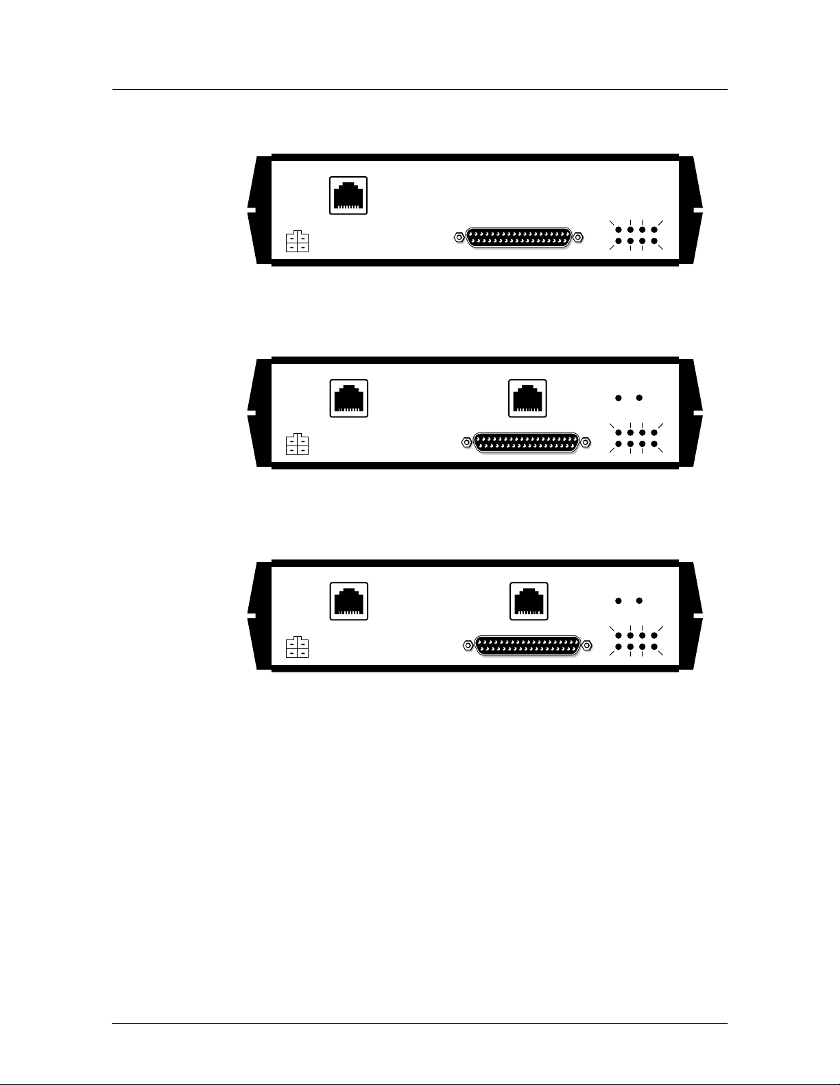
Figure 1-2 Back view of the frame relay and V.35/X.21 CE Speed Touch 591s
Network Port
Power
User Port
Figure 1-3 Back view of the T1 CE Speed Touch 591s
Network Port
Power
T1
User Port
Figure 1-4 Back view of the E1 CE Speed Touch 591s
Network Port
E1
Tx DSR DTR CTS
DCD/I
Rx RTS/C
T1
T1
SIGNAL
ALARM
Tx DSR DTR CTS
DCD/I
Rx RTS/C
E1
E1
SIGNAL
ALARM
MTCE
14636
MTCE
14645
Power
User Port
Tx DSR DTR CTS
DCD/I
Rx RTS/C
MTCE
14637
Speed Touch 591s Technical Practices 1-3
February 2001 90-8785-01
Page 26
1 — Introduction
The Speed Touch 591s provides:
• a network port (RJ45 connector) for connection to the telephone line
• a T1 port (RJ45 connector) for conn ection to data devices or networks (T1 version
only)
• an E1 port (RJ45 connector) for connection to data devices or networks (E1
version only)
• a user port (DB37 connector) for connection to data devices or networks
• a serial port (RJ45 con nect or) for connection to a VT100 termin al f or l ocal node
management sessions
• a power cable connector
Note — The E1 circuit emulation ver sion of the Speed Touch 591s is
designed for use with 120
Ω/75 Ω twisted pair or coaxial cable adapter must be fitted when
using 75
Ω E1 coaxial cabling.
The Speed Touch 591s has its own NMTI, which can be accessed either locally on
the serial port, or remotely using a 5620 Network Manager.
Table 1-1 lists the power requirements for the Speed Touch 591s.
Ω E1 twisted pair cabling . An exter nal 120
1.3 Compatibility
The Speed Touch 591s is compatible with:
• Release 4.1 (and later) of the 5620 Network Manager
• Release 1.0 (and later) of the 7350 ASAM
• Release 4.1.10 (and later) of the 7300 ASAM
Note — The Speed Touch 591s can be mana ged via CPSS us ing the
5620 Network Manager only when it is co nnec te d to a 7350 ASAM.
When the Speed Touch 591s is conne cted to a 7300 ASAM, the only
management operations that can be carried out are Telnet and
software downloads. Software must be downloaded over ATM
connections from workstations not running CPSS.
Table 1-1 Speed Touch 591s power requirements
Specification Value
Power consumption 11.5 W
Voltage range 90 to 132 V ac, 60 Hz
(North America)
180 to 264 V ac, 50 Hz
(Rest of the world)
1-4 Speed Touch 591s Technical Practices
90-8785-01 February 2001
Page 27

1.4 Part numbers
Table 1-2 lists part numbers for the various versions of the Speed Touch 591s.
Component Part number
Speed Touch 591s V.35 FR, Release 2.0 90-8056-01
Speed Touch 591s V.35 CE, Release 2.0 90-8056-02
Speed Touch 591s T1 CE, Release 2.0 90-8057-01
Speed Touch 591s E1 CE, Release 2.0 90-8057-02
Ω external adapter for E1 circuit emulation
75
Speed Touch 591s
Power adapter - 115 V (North America) 90-5989-01
Power adapter - 230 V (International) 90-5990-40
Power adapter - 230 V (IEC, no cord) 90-5990-41
Power adapter - 230 V (United Kingdom) 90-5990-42
Power adapter - 230 V (Europe) 90-5990-43
User port V.36/TIA/EIA-449 cable 90-3576-01
User port V.35 cable 90-3577-01
User port X.21 cable 90-3578-01
Speed Touch 591s Technical Practices, Release 2.0 90-8785-01
1 — Introduction
Table 1-2 Part numbers for the Speed Touch 591s
90-7343-01
Speed Touch 591s Technical Practices 1-5
February 2001 90-8785-01
Page 28

1 — Introduction
1-6 Speed Touch 591s Technical Practices
90-8785-01 February 2001
Page 29

2 — Features and typical applications
2.1 Frame relay 2-2
2.2 V.35/X.21 circuit emulation 2-4
2.3 T1/E1 circuit emulation 2-5
Speed Touc h 591s Technical Practices 2-1
February 2001 90-8785-01
Page 30
2 — Features and typical applications
2.1 Frame relay
The frame relay Speed Touch 591s provides the following key features:
• support for SHDSL payload rates of 192, 384, 512, 768, 1024, 11 52, 1536, 2048,
and 2304 kb/s
• frame relay UNI, PVC support
• frame relay QoS, providing four service categories:
• real time
• low delay
• committed throughput
• best effort
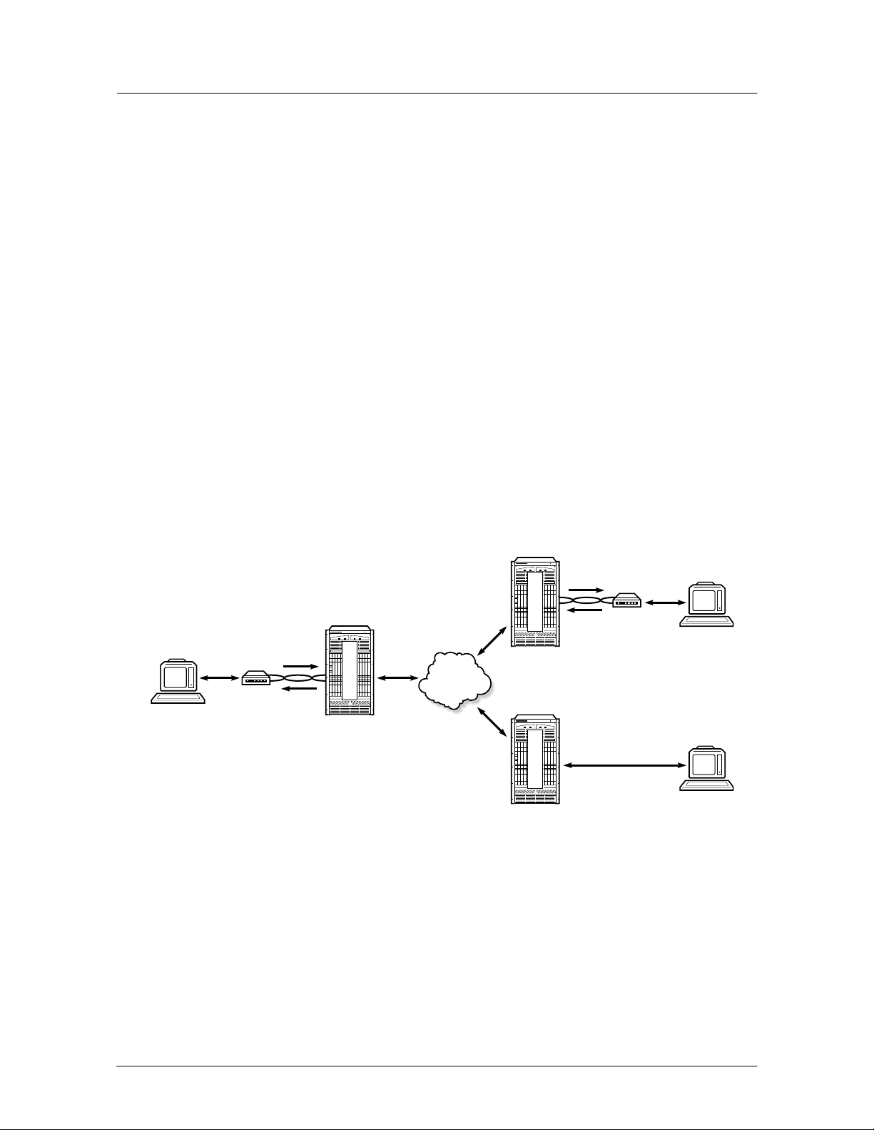
• frame-relay-to-ATM network interworking, allowing two frame relay devices to
be connected over an ATM network with guaranteed quality of service over the
entire line (see Figure 2-1)
• frame-relay-to-ATM service interworking, allowing a frame relay device to be
connected to an ATM device over an ATM network (see Figure 2-2)
• frame forwarding, allowing th e system to suppor t packet-ori ented protocol s such
as X.25 and PPP, which use HDLC-based packets, and to transport them across
an ATM network (see Figure 2-3)
Frame relay
user
ST591s
SHDSL
Figure 2-1 Network interworking
S
H
D
S
L
7350 ASAM
ATM
network
S
H
D
S
L
7350 ASAM
F
R
7350 ASAM
SHDSL
ST591s
Frame relay
user
T1/FR
Frame relay
user
15105
2-2 Speed Touch 591s Technical Practices
90-8785-01 February 2001
Page 31

Figure 2-2 Service interworking
2 — Features and typical application s
Frame relay
Frame
relay
network
Frame user
(PPP, X.25, etc.
protocols)
user
ST591s
ST591s
ST591s
SHDSL
SHDSL
S
H
SHDSL
D
S
L
7300 ASAM
Figure 2-3 Frame forwarding
S
H
D
S
L
7350 ASAM
ATM
network
ATM
network
S
H
D
S
L
7350 ASAM
S
H
D
S
L
7350 ASAM
7350 ASAM
SHDSL
ST591s
SHDSL
ST591s
ATM
terminal
ATM
terminal
15104
Frame user
Frame
network
7350 ASAM
15106
Speed Touch 591s Technical Practices 2-3
February 2001 90-8785-01
Page 32

2 — Features and typical applications
2.2 V.35/X.21 circuit emulation
The V.35/X.21 circuit emulation Speed Touch 591s provides the following key
features:
• support for SHDSL payload rates of 192, 384, 512, 768, 1024, 11 52, 1536, 2048,
and 2304 kb/s
• support for V.35/X.21 circuits at 64 to 2048 kb/s
• support for unstructured or structured data transfer in AAL1 mode
• partial cell filling
• one-to-one mapping between the circuit and one VPI/VCI
Figure 2-4 shows a typical applic ation for th e V.35/X.21 cir cuit emulation ve rsion of
the Speed Touch 591s.
Figure 2-4 Typical V.35/X.21 circuit emulation application
7350
ASAM
SHDSL
PBX
PBX
Router
Phone
V.35
data device
3600
MainStreet
node
ST591s
ST591s
SHDSL
SHDSL
7350
7350
ASAM
ASAM
S
H
D
S
L
S
H
D
S
L
ATM
network
E
1
C
E
7350
ASAM
SHDSL
E1
ST591s
ST591s
3600
MainStreet
node
V.35
data device
3600
MainStreet
node
HDSL
Router
HDLC/
frame
relay
2801
MainStreet
DTU
V.35
data device
15703
2-4 Speed Touch 591s Technical Practices
90-8785-01 February 2001
Page 33

2.3 T1/E1 circuit emulation
The T1/E1 circuit emulati on versions of the Speed Touch 591s provide the followi ng
key features:
• support for SHDSL payload rates of 192, 384, 512, 768, 1024, 11 52, 1536, 2048,
and 2304 kb/s
• support for up to 24 T1 or 31 E1 circuits
• support for unstructured or structured data transfer in AAL1 mode
• support for data and signaling trunk conditioning
• one-to-one mapping between one channel group and one VPI/VCI
Figure 2-5 shows a typical application for the T1 and E1 circuit emulation versions
of the Speed Touch 591s.
Figure 2-5 Typical T1/E1 circuit emulation application
2 — Features and typical application s
T1/E1
device
T1/E1
device
ST591s
ST591s
SHDSL
SHDSL
S
H
D
S
L
7350
ASAM
ATM
network
E
1
C
E
7350
ASAM
E1
S
H
D
S
L
7350
ASAM
3600
MainStreet
node
SHDSL
ST591s
PBX
Router
Phone
T1/E1
device
15702
Speed Touch 591s Technical Practices 2-5
February 2001 90-8785-01
Page 34

2 — Features and typical applications
2-6 Speed Touch 591s Technical Practices
90-8785-01 February 2001
Page 35

Installation
3 — Installation
Speed Touch 591s Technical Practices
February 2001 90-8785-01
Page 36

Page 37

3 — Installation
3.1 Verifying the shipment 3-2
3.2 Installing the Speed Touch 591s and power supply 3-3
Speed Touc h 591s Technical Practices 3-1
February 2001 90-8785-01
Page 38

3 — Installation
3.1 Verifying the shipment
Verify the Speed Touch 591s shipment for completeness and serviceability.
Procedure 3-1 Verifying the shipment
1 Make up an inventory form (see sample form in Table 3-1). As you unpack, record
the description, part number, serial number, and manufacturing code of each
component in the appropriate column.
2 Check each package against the order form and packing slip to ensure that all
contents of the shipment were received. If the shipment is incorrect or incomplete,
contact your sales representative.
3 Check each package for damage. If a package is damaged, contact your sales
representative.
4 Put on the antistatic wrist strap, and connect it to a grounded point.
5 Open each package and inspect all components. If a component is damaged,
contact your sales representative.
6 Complete the shipment verification process.
a If you are installing the components immediately, put them on an antistatic
surface and follow the installation steps.
b If you are not installing the components immediately, repack them in their
original packaging.
3-2 Speed Touch 591s Technical Practices
90-8785-01 February 2001
Page 39

3 — Installation
Table 3-1 Sample inventory form
Item Description Part number Serial number Manufacturing code
1
2
3
4
5
6
7
8
9
10
3.2 Installing the Speed Touch 591s and power supply
Warning — 1 The network cable on the Speed Touch 591s must be
fitted with a ferrite bead to meet EMC regulation s.
Warning — 2 Do not stack units on top of ea ch other . The generat ed
heat causes overheating that may affect the operation of the unit and
may void your warranty.
Site requirements
The Speed Touch 591s must be installed in a clean, dry, well-ventilated area that
meets the requirements listed in Table 3-2.
Speed Touch 591s Technical Practices 3-3
February 2001 90-8785-01
Page 40

3 — Installation
Table 3-2 Site requirements
Item Specifications
Temperature Shipping and storage: -40° to 70°C (-40° to 158°F)
Operating: 0° to 40°C (32° to 104°F)
Standalone ac
power source
Unswitched, separate circuit providing one of the following ranges:
• North America: 104 to 127 V ac (120 V ac -13% to +6%)
• Europe and Asia: 198 to 264 V ac (220 V ac -10%, 240 V ac +10%)
• Eastern Europe: 187 to 253 V ac (220 V ac ±15%)
• Japan: 90 to 110 V ac (100 V ac ±10%)
Humidity 5% to 95% relative humidity, noncondensing (maximum 32 g of water per
Altitude Within an atmospheric pressure range of 60 m (197 ft) below sea level and
Proximity to
sources of
electromagnetic
radiation
cubic meter of air, or 0.024 lb of water per pound of air)
1800 m (5905 ft) above sea level
Although this unit has been designed and tested to meet all relevant standards
of conducted and radiated electromagnetic interference, it may be affected by
strong sources of electromagnetic radiation nearby, such as elevators, air
conditioners, photocopiers, and facsimile machines.
Hardware required
The Speed Touch 591s power supply (see Table 1-2) and ferrite bead (supplied by
the customer) are required.
3-4 Speed Touch 591s Technical Practices
90-8785-01 February 2001
Page 41

3 — Installation
Procedure 3-2 Installing the Speed Touch 591s
1 Plug in the power supply to the power outlet on the Speed Touch 591s.
2 Plug in the power supply to an electrical outlet.
3 Plug the network cable into the network port.
4 Clip the ferrite bead around the network cable as close to the network connector as
possible; see Figure 3-1.
Figure 3-1 Attaching the ferrite bead
Ferrite bead
Network cable
Network connector
14432
Speed Touch 591s Technical Practices 3-5
February 2001 90-8785-01
Page 42

3 — Installation
3-6 Speed Touch 591s Technical Practices
90-8785-01 February 2001
Page 43

Configuration
4 — Configuring generic node parameters
5 — Configuring frame relay port parameters
6 — Configuring frame relay connections
7 — TCA profiles
8 — Configuring the V.35/X.21 CE user port
9 — Configuring V.35/X.21 CE connections
10 — Configuring the T1/E1 CE port
11 — Configuring T1/E1 CE connections
12 — Configuring T1/E1 CE channel groups
Speed Touch 591s Technical Practices
February 2001 90-8785-01
Page 44

Page 45

4 — Configuring generic node parameters
4.1 Node parameter configuration 4-2
4.2 Configuring the network port 4-8
Speed Touc h 591s Technical Practices 4-1
February 2001 90-8785-01
Page 46

4 — Configuring generic node parameters
4.1 Node parameter configuration
The softkey structure for configuring node parameters is shown below.
HOUSE
SER_PORT_1
NODE_NAME <name> ↵
MORE...
BAUD_RATE
SESS_TIMEOUT CHNG_PSSWD <password> ↵ IP_ADDRESSES DSLAM_TYPE LEVEL_0
ENABLE*/
HOURS <hours> ↵DEFAULT
7350* 7300
DISABLE
MINUTES <minutes> ↵
CTLIP <ipaddress> ↵
DESTIP <ipaddress> ↵
SUBNET_MASK <mask> ↵
CTL_VP/VC <vpi/vci> ↵
PROG_TO_CURR
SK002933
Table 4-1 lists the node par ameter s tha t can be confi gured o n the Sp eed Touc h 591 s.
Table 4-1 Node parameters
Parameter Options Default value
Baud rate 600, 1200, 2400, 4800, 9600, 19200 9600
Node name 8- to 12-character string —
Session timeout 1 min to 24 h 12 h
Password 15-character string mainstreet
Level 0 access Enable, Disable Enable
DSLAM type 7350, 7300 7350
Control IP address
Destination IP address
Subnet mask
Control VP/VC
(1)
(1)
(1)
IP address of the Speed Touch 591s 0.0.0.0
(1)
IP address of gateway 0.0.0.0
Subnet mask for the domain in which the
Speed Touch 591s and gateway are
located
VP/VC on which the control signals will
be carried
255.255.255.0
0/32
Note
(1)
This softkey is displayed only when the DSLAM type is configured as 7300.
4-2 Speed Touch 591s Technical Practices
90-8785-01 February 2001
Page 47

4 — Configuring generic node parameters
Configuring the serial port baud rate
The Speed Touch 591s provides a serial port for connection to serial
transmission-based node management terminals. Initially, the baud rate of the node
management terminal must be set to match the Speed Touch 591s default value of
9.6 kb/s to establ ish communication. Aft er the terminal establi shes connection, a new
baud rate can be configured for the serial port.
If the serial port baud rate is changed, the change takes effect when PROCEED is
selected. Change the baud rate of the node management terminal to match the new
baud rate of the serial port.
Procedure 4-1 Configuring the baud rate
HOUSE — SER_PORT_1 — BAUD_RATE — 600 or 1200 or 2400 or 4800 or 9600* or 19200
Configuring the node name
When the node name is configured, it is displayed in the header line. If it is not
configured, the node name is left blank.
Procedure 4-2 Configuring the node name
HOUSE — NODE_NAME — <name> ↵
where name contains a maximum of 12 alphanumeric characters excluding space, tab,
question mark, and percent sign
Configuring the NMTI session timeout
The session timeout for the NMTI on the Speed To uch 591s can be con figured or se t
to zero (0) to disable it.
Speed Touch 591s Technical Practices 4-3
February 2001 90-8785-01
Page 48

4 — Configuring generic node parameters
Procedure 4-3 Configuring the NMTI session time ou t
1 Select:
HOUSE — MORE — SESS_TIMEOUT
2 Enter the desired session timeout setting:
a To set the timeout to its default setting of 12 h, select:
DEFAULT
b To set the timeout to a specific number of minutes, enter:
MINUTES — <minutes> ↵
where minutes is a value between 0 and 59
c To set the timeout to a specific number of hours, enter:
HOURS — <hours> ↵
where hours is a value between 1 and 24
Changing the password
The defaul t password for the Speed T ouch 591s is set to <mains treet>. Passwords
must contain between 8 and 12 alp hanu meric ch aract ers with no spa ces, and are not
case sensitive.
When the unit is first commissioned, all passwords should be changed to prevent
unauthorized use.
The screen does not displa y the password as it is ent ered. If you make a typ ing error,
press <Esc> and select CANCEL. The system returns to the HOUSE menu display.
Procedure 4-4 Changing the password
HOUSE — MORE — CHNG_PSSWD — <password> ↵
where password contains 8 to 12 alphanumeric c haracters excluding space, tab, period,
question mark, and percent sign
4-4 Speed Touch 591s Technical Practices
90-8785-01 February 2001
Page 49

4 — Configuring generic node parameters
Configuring the DSLAM type
The Speed Touch 591s can be configured to be compatible with either of two types
of DSLAM—DSLAMs that support CPSS or DSLAMs that do not support CPSS.
If the Speed Touch 591s i s con nected to a 7350 ASAM, con figur e the DSLAM type
as 7350. If the Speed Touch 591s is connected to a 7300 ASAM or any other
DSLAM, configure the DSLAM type as 7300.
Note — Configuration of this parameter does not affect SHDSL
interoperability—it only specifies how the Speed Touch 591s
communicates with the DSLAM for management purposes.
Procedure 4-5 Configuring the DSLAM typ e
HOUSE — MORE — DSLAM_TYPE — 7350* or 7300
Configuring the control IP address
The control IP address is the IP address of the Speed Touch 591s. It can be
configured manually when the Speed Touch 591s is operating with a 7300 ASAM.
Note — The new IP address is not applied until the destination IP
address, subnet mask, and control VP/VC have been correctly
configured individually, and the configuration has been applied
globally—see procedure 4-10.
Procedure 4-6 Configuring the control IP address
HOUSE — MORE — IP_ADDRESSES — CTLIP — <ipaddress> ↵
where ipaddress is the IP address of the Speed Touch 591s in the decimal format #.#.#.#
and where # is in the range 0 to 255
Speed Touch 591s Technical Practices 4-5
February 2001 90-8785-01
Page 50

4 — Configuring generic node parameters
Configuring the destination IP address
The destination IP address is the IP address of the remote host.
Note — The new IP address is not applied until the control IP
address, subnet mask, and control VP/VC have been correctly
configured individually, and the configuration has been applied
globally—see procedure 4-10.
Procedure 4-7 Configuring the destination IP address
HOUSE — MORE — IP_ADDRESSES — DESTIP — <ipaddress> ↵
where ipaddress is the IP address of the gateway in the decimal format #.#.#.# and where
# is in the range 0 to 255
Configuring the subnet mask
The subnet mask for the domain containing the Speed Touch 591s must be
configured manually when the Speed Touch 591s is operating with a 7300 ASAM.
Note — The new mask is not applied until the control IP address,
destination IP address, and control VP/VC have been correctly
configured individually, and the configuration has been applied
globally—see procedure 4-10.
Procedure 4-8 Configuring the subnet mask
HOUSE — MORE — IP_ADDRESSES — SUBNET_MASK — <mask> ↵
where mask is the subnet mas k in the decimal format # .#.#.# and where # is in the range
0 to 255
Configuring the control VP/VC
The VP/VC used to carr y management si gnals can be configured man ually when the
Speed Touch 591s is operating with a 7300 ASAM, because the 7300 ASAM does
not support CPSS signals.
Note — The new control VP/VC is not applied until the control IP
address, destinat ion IP ad dress , and s ubnet mask have bee n corre ctly
configured individually, and the configuration has been applied
globally—see procedure 4-10.
4-6 Speed Touch 591s Technical Practices
90-8785-01 February 2001
Page 51

4 — Configuring generic node parameters
Procedure 4-9 Configuring the control VP/VC
HOUSE — MORE — IP_ADDRESSES — CTL_VP/VC — <0/vci> ↵
where vci is a VCI number in the range 32 to 158
Applying the IP address configuration
The IP address parameters are not applied until they have all been correctly
configured individually, and the configuration has been applied globally.
Procedure 4-10 Applying the IP address configuration
HOUSE — MORE — IP_ADDRESSES — PROG_TO_CURR
Configuring level 0 access
The system has six access levels, numbered 0 to 5. Enter your access level and
password when you log in. Refer to Alcatel 7350 ASAM Technical Practices for
further information on access levels. Level 0 access allows read-only access to all
node management functions on the Speed Touch 591s and does not require a
password. Only a level 5 user can configure level 0 access.
Procedure 4-11 Configuring level 0 access
HOUSE — MORE — LEVEL_0 — ENABLE* or DISABLE
Speed Touch 591s Technical Practices 4-7
February 2001 90-8785-01
Page 52

4 — Configuring generic node parameters
4.2 Configuring the network port
Since the Speed Touch 591s is a slave to the CO device at the other end of the
SHDSL line, the majority of network port parameters are configured by the CO
device.
The CO device can configure, enable, or disable the following parameters on the
network port on the Speed Touch 591s:
• SHDSL line rate (192, 384, 512, 768, 1024, 1152, 1536, 2048, or 2304 kb/s)
• signal-to-noise margin threshold
• power backoff
• loopbacks
• PSD mask used on the SHDSL line (Europ ean or North Ame rican, s ymmetric or
asymmetric)
The only network por t par ameter that can be confi gured lo cally on the Speed Touch
591s NMTI is power backoff.
Power backoff
The power backoff feature automatically reduces the power transmitted by the
network port over the SHDSL line. During the line training phase, the transmitted
power is compared with the strengt h of the signal received at the other end of the line.
If possible , transmit power is then reduced to a level that is sufficient for th e signal
to be correctly rec eived at the other end of th e line while still mainta ining a maximum
BER of 10
-7
.
On short or relatively loss-free lines, this feature reduces the risk of crosstalk being
generated on neighb ori ng l in es b y unne ces sa rily strong signals whe n a l ower si gna l
strength would still produce a clean signal at the receiver.
Note — Power backoff configurations contained in EOC requests
from CO devices at the other end of the SHDSL line override any
local NMTI power backoff c onfigurations on the Sp eed Touch 591s.
Procedure 4-12 Configuring power backoff
CONFIG — OBJECT — PORT — <N> ↵ — LINE_CFG — ENABLE_PBO/DISABLE_PBO
4-8 Speed Touch 591s Technical Practices
90-8785-01 February 2001
Page 53

5 — Configuring frame relay port
parameters
5.1 Configuring the user port name and options 5-2
5.2 Configuring the user port stream 5-6
5.3 Configuring user port stream options 5-8
5.4 Configuring frame forwarding stream options 5-14
Speed Touc h 591s Technical Practices 5-1
February 2001 90-8785-01
Page 54

5 — Configuring frame relay port parameters
5.1 Configuring the user port name and options
The softkey structure for configuring th e name and options for th e Speed Touch 591s
user port is shown below.
CONFIG
OBJECT
PORT <U> ↵
CLOCK_RATE
INPUTS
DTR
C
DSR
RTS
NAME <name> ↵
CTRL_LEADS
OUTPUTS
DCD/I
CTS
SET_DEFAULT
TM
V.35*
OPTIONS
IF_TYPE
V.36/TIA-449
SLAVE*
MODE
EXTERNAL
CLOCKING
X.21
ENABLE
TX_INVERT
DISABLE*
SK002115
5-2 Speed Touch 591s Technical Practices
90-8785-01 February 2001
Page 55

5 — Configuring frame relay port parameters
Table 5-1 lists the user port parameters that can be configured.
Table 5-1 User port parameters
Parameter Options Default value
Name 15-character string —
Clock rate 9.6, 19.2, 48, and
Interface type V.35, V.36/TIA/EIA-449,
Clocking mode DCE slave, DCE external
Clock inversion Enable, Disable Disable
Control leads C
(X.21)
DTR
(V.35/V.36)
RTS
(V.35/V.36)
DSR (V.35/V.36) Force On, Force Off Force On
DCD (V.35/V.36)
I (X.21)
CTS (V.35/V.36) Active, Force On, Force
TM (V.35) Force On, Force Off,
n
× 64 (n = 1 to 32)
X.21
(V35/V36 only)
Active, Assume On,
Assume Off
Active, Assume On,
Assume Off
Active, Assume On,
Assume Off
Active, Force On, Forc e
Off
Off
Ind_maint
(1)
512 kb/s
V.35
DCE slave
Active
Active
Active
Active
Active
Ind_maint
Note
(1)
When the test mode lead is set to Ind_maint, it is controlled by software-initiated maintenance. The
lead is forced on when a maintenance action such as a loopback is applied to the unit, and it is forced
off when all maintenance actions are removed.
Procedure 5-1 Naming the user port
CONFIG — OBJECT — PORT — <U> ↵ — NAME — <name> ↵
where name contains a maximum of 15 characters excluding space, tab, period, question
mark, and percent sign
Speed Touch 591s Technical Practices 5-3
February 2001 90-8785-01
Page 56

5 — Configuring frame relay port parameters
Procedure 5-2 Configuring the interface type
CONFIG — OBJECT — PORT — <U> ↵ — OPTIONS — IF_TYPE — V.35* or TIA-449 or X.21
Note — Every time the interface type is changed, the user port reverts
to the disabled state and must be enabled again. Refer to section 13.3 for
details on how to enable the user port. The default interface type is V.35.
Procedure 5-3 Configuring input cont rol lea ds
1 Enter:
CONFIG — OBJECT — PORT — <U> ↵ — OPTIONS — CTRL_LEADS — INPUTS
2 Select:
a For X.21:
C
b For V.35 and V.36/TIA-449:
DTR or RTS
3 Select:
ASSUME_ON or ASSUME_OFF or ACTIVE*
Procedure 5-4 Configuring output contr ol leads
1 Enter:
CONFIG — OBJECT — PORT — <U> ↵ — OPTIONS — CTRL_LEADS — OUTPUTS
2 Select:
DSR or DCD/I or CTS or TM
3 Select:
a For DSR or TM:
FORCE_ON* or FORCE_OFF or IND_MAINT* (TM output only)
b For DCD/I or CTS:
ACTIVE* or FORCE_ON or FORCE_OFF
5-4 Speed Touch 591s Technical Practices
90-8785-01 February 2001
Page 57

5 — Configuring frame relay port parameters
Procedure 5-5 Restoring default values for the control leads
CONFIG — OBJECT — PORT — <U> ↵ — OPTIONS — CTRL_LEADS — SET_DEFAULT
Table 5-1 shows the default values for the control leads.
Procedure 5-6 Configuring the clocking mo de
CONFIG — OBJECT — PORT — <U> ↵ — OPTIONS — CLOCKING — MODE — SLAVE* or
EXTERNAL
Procedure 5-7 Configuring inverted clocking
CONFIG — OBJECT — PORT — <U> ↵ — OPTIONS — CLOCKING — TX_INVERT —
ENABLE or DISABLE*
Procedure 5-8 Configuring the clock rate
CONFIG — OBJECT — PORT — <U> ↵ — OPTIONS — CLOCKING — CLOCK_RATE — 9.6
kb/s or 19.2 kb/ s or 48 kb/s or n*64 kb/s <value> ↵
where value is the value of n (1 to 32), used as a multiplying factor for 64 kb/s
Speed Touch 591s Technical Practices 5-5
February 2001 90-8785-01
Page 58

5 — Configuring frame relay port parameters
5.2 Configuring the user port stream
The softkey structure for configuring the stream on the user port is shown below.
CONFIG
OBJECT
PORT <U> ↵
STREAM
NAME <name> ↵
OPTIONS FRAME_SIZE <size> ↵
FRAME_RELAY
TRANSLATED <profile_number> ↵
APPLICATION
FRAME_FWD
TRANSPARENT
SK002116
Table 5-2 lists the stream parameters that can be configured on the user port.
Table 5-2 Stream parameters
Parameter Options Default value
Name 1 5 -charac ter string —
Frame size 16 to 4472 bytes 1600 bytes
Application type Frame relay
Frame forwarding
(translated or transparent)
—
Procedure 5-9 Configuring the stream name
CONFIG — OBJECT — PORT — <U> ↵ — STREAM — NAME — <name> ↵
where name contains a maximum of 15 characters excluding space, tab, period, question
mark, and percent sign
5-6 Speed Touch 591s Technical Practices
90-8785-01 February 2001
Page 59

5 — Configuring frame relay port parameters
Procedure 5-10 Configuring the frame size
CONFIG — OBJECT — PORT — <U> ↵ — STREAM — FRAME_SIZE — <size> ↵
where size is the desired maximum frame size (16 to 4472 bytes)
Application type
The Speed Touch 591s can be confi gured to ens ure qualit y of servic e for frame relay
traffic over the SHDSL line (in which case, an equivalence is made between certain
frame relay and ATM services), or to simply forward frames.
Procedure 5-11 Configuring the application type
1 Enter:
CONFIG — OBJECT — PORT — <U> ↵ — STREAM — APPLICATION
2 Select the application type:
a For frame relay:
FRAME_RELAY
b For frame forwarding:
FRAME_FWD then
TRANSLATED — <profile_number> ↵ or TRANSPARENT
where profile_number is a user translation profile number (refer to Alcatel 7350
ASAM Technical Practices for further information on frame relay user translation
profiles)
Speed Touch 591s Technical Practices 5-7
February 2001 90-8785-01
Page 60

5 — Configuring frame relay port parameters
5.3 Configuring user port stream options
The softkey structure for configuring frame relay stream options on the user port is
shown below.
CONFIG
OBJECT
PORT <U> ↵
STREAM
OPTIONS
THRESHOLD PACING <value> ↵
NONE*
REAL_TIME
LOW_DELAY COM_THRUPUT BEST_EFFORT
PVC_MGMNT
HEARTBEAT <value> ↵
TYPE
LMI ANNEX_A ANNEX_D AUTO-NET
TIMEOUT <value> ↵
STATUS_RATE <value> ↵
INVERTED/
STANDARD*
HDLC
NUM_FLAGS <number> ↵
ALARM_FILTER
THRESHOLD
STREAM
PVC
SK002900
5-8 Speed Touch 591s Technical Practices
90-8785-01 February 2001
Page 61

5 — Configuring frame relay port parameters
Tables 5-3 and 5-4 list the frame relay stream options that can be configured on the
user port.
Table 5-3 Frame relay stream parameters
Parameter Options Default value
Thresholds REAL_TIME ACT 0 to 3600 ms 500 ms
SCT 0 to 3600 ms 400 ms
MCT 0 to 3600 ms 250 ms
LOW_DELAY ACT 0 to 3600 ms 800 ms
SCT 0 to 3600 ms 625 ms
MCT 0 to 3600 ms 400 ms
COM_THRUPUT
BEST_EFFORT
Pacing Dependent on SHDSL line speed
PVC management See Table 5-4
HDLC Inverted
ACT 0 to 3600 ms 1250 ms
SCT 0 to 3600 ms 1000 ms
MCT 0 to 3600 ms 625 ms
Standard
Standard
Num_flags <number>
Table 5-4 PVC management parameters for a frame relay stream
Parameter Options Default value
Type None
LMI
Annex A
Annex D
Auto-Net
Heartbeat 5 to 30 s,
in increments of 5 s
Timeout 5 to 30 s,
in increments of 5 s
Status rate 1 to 255 6
Threshold Errors 1 to 10 2
Events 1 to 10 4
Alarm filter Stream No. of alarms 0 to 255 8
Interval 0 to 60 min, in increments of
5 min
PVC No. of alarms 0 to 255 3
Interval 0 to 60 min, in increments of
5 min
None
10 s
15 s
10
15
Speed Touch 591s Technical Practices 5-9
February 2001 90-8785-01
Page 62

5 — Configuring frame relay port parameters
QoS thresholds
The quality-of- servi ce thr eshol ds can be set for the four frame relay queues ; ref er t o
Alcatel 7350 ASAM Technical Pr actices for further information on frame relay QoS.
Procedure 5-12 Configuring QoS thresholds
1 Enter:
CONFIG — OBJECT — PORT — <U> ↵ — STREAM — OPTIONS — THRESHOLDS
2 Select:
REAL_TIME or LOW_DELAY or COM_THRUPUT or BEST_EFFORT
3 Select:
ACT or SCT or MCT
4 Enter the desired value for the threshold:
<value> ↵
where value is the queue threshold in ms (see Table 5-3 for values)
Pacing
The Speed Touch 591s uses pacing to control t he rate at wh ich frame relay and frame
forwarding traffi c travel s from the user por t to the networ k port. Pac ing smooths out
traffic peaks so that the data is transmitted more evenly, thus avoiding peaks at the
receiving end, usually a central node. Since the central node receives data
simultaneously from s everal different sources, bursts of data can cause con gestion on
the node. Use of the pacing feature prevents this problem.
The SHDSL line on the Speed Touch 591s network port runs at a much faster rate
than the user port. Without pacing, frames arriving on the user port would be
converted to ATM cells and sent out at the SHDSL line rate on the network port,
producing bursts of data at the receiving end. Pacing allows the data frames to be
more evenly spread in cells on the SHDSL line, with empty cells inserted between
data cells. Th is helps with traff ic management on the r eceiving e nd because the node
can discard the empty cells, giving it more time to process the data cells.
Default pacing values are calculated and applied by the Speed Touch 591s as a
function of the user port clock rate (see section 5.1 for details) and the SHDSL line
rate. The device on the other end of the SHDSL line dic ta tes the li ne rate across the
SHDSL line because the Speed Touch 591s acts as a slave device.
5-10 Speed Touch 591s Technical Practices
90-8785-01 February 2001
Page 63

5 — Configuring frame relay port parameters
Procedure 5-13 Configuring pacing
CONFIG — OBJECT — PORT — <U> ↵ — STREAM — OPTIONS — PACING — <value> ↵
where value is a pacing rate in kb/s
HDLC
The Speed Touch 591s user port can be configured to support either standard or
inverted HDLC. The minimum number of flags t ran smit ted between HDLC frames
can also be configured. The default setting is 1 flag (back-to-back frames).
Procedure 5-14 Configuring HDLC
CONFIG — OBJECT — PORT — <U> ↵ — STREAM — OPTIONS — HDLC — INVERTED or
STANDARD* or NUM_FLAGS — <number> ↵
where number is the number of HDLC flags between frames, in a range from
1 to 10
Procedure 5-15 Configuring the PVC management type
1 Enter:
CONFIG — OBJECT — PORT — <U> ↵ — STREAM — OPTIONS — PVC_MGMNT —
TYPE
2 Select:
NONE or LMI or ANNEX_A or ANNEX_D or AUTO-NET
3 Select:
a For LMI:
USER or NETWORK or NETEXT
b For ANNEX_A or ANNEX_D:
USER or NETWORK or BIDIR
Speed Touch 591s Technical Practices 5-11
February 2001 90-8785-01
Page 64

5 — Configuring frame relay port parameters
Procedure 5-16 Configuring the heartbeat
CONFIG — OBJECT — PORT — <U> ↵ — STREAM — OPTIONS — PVC_MGMNT —
HEARTBEAT — <value> ↵
where value is a multiple of 5 in the range 5 to 30 s
Procedure 5-17 Configuring the timeout
CONFIG — OBJECT — PORT — <U> ↵ — STREAM — OPTIONS — PVC_MGMNT —
TIMEOUT — <value> ↵
where value is a multiple of 5 in the range 5 to 30 s
Procedure 5-18 Configuring the status rate
CONFIG — OBJECT — PORT — <U> ↵ — STREAM — OPTIONS — PVC_MGMNT —
STATUS_RATE — <value> ↵
where value is a number of polling cycles from 1 to 255
Procedure 5-19 Configuring the error and event thresholds
1 Enter:
CONFIG — OBJECT — PORT — <U> ↵ — STREAM — OPTIONS — PVC_MGMNT —
THRESHOLD
2 Enter:
ERRORS — <errors> ↵
where errors is the number of allowable errors (see Table 5-4)
3 Enter:
EVENTS — <events> ↵
where events is the number of allowable events (see Table 5-4)
5-12 Speed Touch 591s Technical Practices
90-8785-01 February 2001
Page 65

5 — Configuring frame relay port parameters
Procedure 5-20 Configuring the alarm filter
1 Enter:
CONFIG — OBJECT — PORT — <U> ↵ — STREAM — OPTIONS — PVC_MGMNT —
ALARM_FILTER
2 Select:
STREAM or PVC
3 Enter:
#ALARMS — <alarms> ↵
where alarms is the number of alarms in the interval (see Table 5-4)
4 Enter:
INTERVAL — <interval> ↵
where interval is the interval over which the alarms are detected (see Table 5-4)
Speed Touch 591s Technical Practices 5-13
February 2001 90-8785-01
Page 66

5 — Configuring frame relay port parameters
5.4 Configuring frame forwarding stream options
The softkey structure for configuring frame forwarding stream options on the user
port is shown below.
CONFIG
OBJECT
PORT <U> ↵
STREAM
OPTIONS
PACING <value> ↵
ACT <value> ↵
Congestion thresholds
THRESHOLD
SCT <value> ↵ MCT <value> ↵
INVERTED/
STANDARD*
HDLC
NUM_FLAGS <number> ↵
TCA_PROFILE
SK002118
The procedures for configuring pacing and HDLC are the same as for frame relay
streams—refer to procedures 5-13 and 5-14 respectively for details. TCA profiles
and their configuration procedure are described in chapter 7.
Thresholds can be c onfigured for the three levels of conge stion: absolute, severe, and
mild.
Procedure 5-21 Configuring congestion thresh o lds
CONFIG — OBJECT — PORT — <U> ↵ — STREAM — OPTIONS — THRESHOLDS — ACT or
SCT or MCT — <value> ↵
where value is the desired threshold in ms (see Table 5-3)
5-14 Speed Touch 591s Technical Practices
90-8785-01 February 2001
Page 67

6 — Configuring frame relay connections
6.1 Configuring frame relay connection options 6-2
6.2 Configuring frame relay traffic parameters 6-4
6.3 Configuring network interworking 6-5
6.4 Configuring service interworking 6-7
6.5 Configuring frame forwarding connection options 6-8
Speed Touc h 591s Technical Practices 6-1
February 2001 90-8785-01
Page 68

6 — Configuring frame relay connections
6.1 Configuring frame relay connection options
The softkey structure for configuring frame relay connection options is shown
below.
CONFIG
CONNECT <endpoint> ↵
SHOW_GROUP
DISCONNECT
TRANSLATED
<profile no.> ↵STANDARD
TO_ENDPOINT <endpoint> ↵
NETWORK_IWF
TRANSPARENT*
TRAFFIC
FROM_1—>2
CLP_MAPPINGDE_MAPPINGPVC_MGMNT
NIW_DLCI <dlci> ↵
CLP_MAPPINGDE_MAPPING
INTERWORKING
RATESPOLICINGFR_SERV_CAT
SERVICE_IWF
EFCI_MAPPING
The following procedures des cr ibe how to sel ec t fr ame relay connection endpoints,
display connection information, and disconnect endpoints.
Frame relay connection endpoints
SK002119
Connections are cr eated be tween the u ser and ne twork port s, and are thus int ernal t o
the unit. A connection is identified by its two endpoints—one at the user port, the
other at the network port . The two endpoints are se lec te d as described below. Refe r
to Alcatel 7350 ASAM Technical Practices for further information on endpoint
identifiers.
6-2 Speed Touch 591s Technical Practices
90-8785-01 February 2001
Page 69

6 — Configuring frame relay connections
Procedure 6-1 Selecting the two frame relay connectio n end po i nts
1 Enter:
CONFIG — CONNECT — <endpoint> ↵
where endpoint is in the format <U;S1/Ddlci> or <U;Ddlci>, and dlci is a value from
16 to 1007 (S1 is implicit; it does not have to be specified)
2 Enter:
TO_ENDPOINT — <endpoint> ↵
where endpoint is in the format <N;0/vci>, and vci is a VCI number from 32 to 157
Connection information
Connection informat ion ca n be dis playe d for t he endpo ints of t he PVCs. For furt her
details on the connection information available, refer to Alcatel 7350 ASAM
Technical Practices.
Procedure 6-2 Displaying connection information
1 Select one of the two endpoints:
CONFIG — CONNECT — <endpoint> ↵
where endpoint is in the format <U;S1/Ddlci> or <U;Ddlci>, and dlci is a value from
16 to 1007, or <N;0/vci>, and vci is a VCI number from 32 to 157
2 Select:
SHOW_GROUP
3 If there are too many connections to fit on the screen, select an option to view the
other connections.
a For connections further down the list, select:
PAGE_DOWN
b For connections near the beginning of the list, select:
PAGE_UP
4 To display the original connection information, select:
SHOW_CONNECT
Speed Touch 591s Technical Practices 6-3
February 2001 90-8785-01
Page 70

6 — Configuring frame relay connections
Procedure 6-3 Disconnecting an end po int
A connection can be disconnected by disconnecting either endpoint.
CONFIG — CONNECT — <endpoint> ↵ — DISCONNECT
where endpoint is in the format <U;S1/Ddlci> or <U;Ddlci>, and dlci is a value from 16 to
1007, or <N;0/vci>, and vci is a VCI number from 32 to 157
6.2 Configuring frame relay traffic parameters
Table 6-1 lists the traffic parameters that can be configured on the ST591s.
Table 6-1 Traffic parameters
Parameter Possible values Default value
FR service category REAL_TIME
LOW_DELAY
COM_THRUPUT
BEST_EFFORT
Policing Enable, Disable Enable
Rates CIR 0 - AR kb/s
Bc 0 - 65535 kb/s 0 kb/s
Be 0 - 65535 kb/s AR kb/s
(1)
BEST_EFFORT
0 kb/s
Note
(1)
Access rate is the effective maximum bandwidth of a frame relay port.
Procedure 6-4 Configuring the service categ or y
CONFIG — CONNECT — <endpoint> ↵ — TRAFFIC — FROM_1→2 — FR_SERV_CAT —
REAL_TIME or LOW_DELAY or COM_THRUPUT or BEST_EFFORT*
where endpoint is in the format <U;S1/Ddlci> or <U;Ddlci>, and dlci is a value from 16 to
1007, or <N;0/vci>, and vci is a VCI number from 32 to 157
For further information on service categories, refer to Alcatel 7350 ASAM Technical
Practices.
6-4 Speed Touch 591s Technical Practices
90-8785-01 February 2001
Page 71

6 — Configuring frame relay connections
Procedure 6-5 Configuring policing
CONFIG — CONNECT — <endpoint> ↵ — TRAFFIC — FROM_1 →2 — POLICING — ENABLE*
or DISABLE
where endpoint is in the format <U;S1/Ddlci> or <U;Ddlci>, and dlci is a value from 16 to
1007, or <N;0/vci>, and vci is a VCI number from 32 to 157
For further information on policing, refer to Alcatel 7350 ASAM Technical Practices.
Procedure 6-6 Configuring rates
CONFIG — CONNECT — <endpoint> ↵ — TRAFFIC — FROM_1→2 — RATES — CIR or Bc or
Be or CIR=Bc — <value>K ↵
where
endpoint is in the format <U;S1/Ddlci> or <U;Ddlci>, and dlci is a value from 16 to 1007,
or <N;0/vci>, and vci is a VCI number from 32 to 157
value is the desired rate in kb/s
6.3 Configuring network interworking
Table 6-2 lists the network interworking parameters that can be configured on the
Speed Touch 591s.
Table 6-2 Network interworking parameter s
Parameter Options Default value
PVC management Enable, Disable Enable
DE mapping DE=CLP
DE=FR_SSCS
CLP mapping CLP=DE
CLP=0
CLP=1
NIWF DLCI 16 to 991
1022
DE=CLP
CLP=DE
1022
Speed Touch 591s Technical Practices 6-5
February 2001 90-8785-01
Page 72

6 — Configuring frame relay connections
Procedure 6-7 Configuring PVC management
CONFIG — CONNECT — <endpoint> ↵ — INTERWORKING — NETWORK_IWF —
PVC_MGMNT — ENABLE* or DISABLE
where endpoint is in the format <U;S1/Ddlci> or <U;Ddlci>, and dlci is a value from 16 to
1007, or <N;0/vci>, and vci is a VCI number from 32 to 157
Procedure 6-8 Configuring DE mapping
CONFIG — CONNECT — <endpoint> ↵ — INTERWORKING — NETWORK_IWF —
DE_MAPPING — DE=CLP* or DE=FR_SSCS
where endpoint is in the format <U;S1/Ddlci> or <U;Ddlci>, and dlci is a value from 16 to
1007, or <N;0/vci>, and vci is a VCI number from 32 to 157
Procedure 6-9 Configuring CLP mapping
CONFIG — CONNECT — <endpoint> ↵ — INTERWORKING — NETWORK_IWF —
CLP_MAPPING — CLP=DE* or CLP=0 or CLP=1
where endpoint is in the format <U;S1/Ddlci> or <U;Ddlci>, and dlci is a value from 16 to
1007, or <N;0/vci>, and vci is a VCI number from 32 to 157
Procedure 6-10 Configuring NIW DLCI
CONFIG — CONNECT — <endpoint> ↵ — INTERWORKING — NETWORK_IWF —
NIW_DLCI — <dlci> ↵
where
endpoint is in the format <U;S1/Ddlci> or <U;Ddlci>, and dlci is a value from 16 to 1007,
or <N;0/vci>, and vci is a VCI number from 32 to 157
dlci is a valid network interworking DLCI (see Table 6-2)
6-6 Speed Touch 591s Technical Practices
90-8785-01 February 2001
Page 73

6.4 Configuring service interworking
Table 6-3 lists the service interworking parameters that can be configured on the
Speed Touch 591s.
Table 6-3 Service interworking parameters
Parameter Options Default value
Mode Translated <profile_no.>
Transparent
DE mapping DE=CLP
DE=0
DE=1
CLP mapping CLP=DE
CLP=0
CLP=1
EFCI mapping EFCI=FECN
EFCI=0
6 — Configuring frame relay connections
Transparent
DE=CLP
CLP=DE
EFCI=FECN
Procedure 6-11 Configuring the interworking mod e
1 Select one of the two connection endpoints:
CONFIG — CONNECT — <endpoint> ↵
where endpoint is in the format <U;S1/Ddlci> or <U;Ddlci>, and dlci is a value from
16 to 1007, or <N;0/vci>, and vci is a VCI number from 32 to 157
2 Select:
INTERWORKING — SERVICE_IWF
3 Select:
a For transparent service interworking:
TRANSPARENT*
b For translated service interworking:
TRANSLATED
then enter:
STANDARD or <profile_no.> ↵
where profile_no. is the number of a configured translation profile; refer to Alcatel
7350 ASAM Technical Practices for further information
Speed Touch 591s Technical Practices 6-7
February 2001 90-8785-01
Page 74

6 — Configuring frame relay connections
Procedure 6-12 Configuring DE mapping
CONFIG — CONNECT — <endpoint> ↵ — INTERWORKING — SERVICE_IWF —
DE_MAPPING — DE=CLP* or DE=0 or DE=1
where endpoint is in the format <U;S1/Ddlci> or <U;Ddlci>, and dlci is a value from 16 to
1007, or <N;0/vci>, and vci is a VCI number from 32 to 157
Procedure 6-13 Configuring CLP mapping
CONFIG — CONNECT — <endpoint> ↵ — INTERWORKING — SERVICE_IWF —
CLP_MAPPING — CLP=DE* or CLP=0 or CLP=1
where endpoint is in the format <U;S1/Ddlci> or <U;Ddlci>, and dlci is a value from 16 to
1007, or <N;0/vci>, and vci is a VCI number from 32 to 157
Procedure 6-14 Configuring EFCI mapping
Select one of the two connection endpoints:
CONFIG — CONNECT — <endpoint> ↵ — INTERWORKING — SERVICE_IWF —
EFCI_MAPPING — EFCI=FECN* or EFCI=0
where endpoint is in the format <U;S1/Ddlci> or <U;Ddlci>, and dlci is a value from 16 to
1007, or <N;0/vci>, and vci is a VCI number from 32 to 157
6.5 Configuring frame forwarding connection options
The softkey structur e for config uring frame fo rwarding conne ction option s is shown
below.
CONFIG
CONNECT <endpoint> ↵
SHOW_GROUP
The procedures for selecting endpoints, displaying connection information and
disconnecting an endpoint for a frame forwarding connection are the same as those
for a frame relay connec tion. Refer to section 6.1 fo r details. Tr affic pacing is
enabled by default and cannot be disabled.
DISCONNECT TO_ENDPOINT <endpoint> ↵
SK002120
6-8 Speed Touch 591s Technical Practices
90-8785-01 February 2001
Page 75

7 — TCA profiles
7.1 Overview 7-2
7.2 TCA profile types and parameters 7-3
7.3 Maximum permissible time 7-4
7.4 FRCC-type TCA profiles 7-5
7.5 FRSC-type TCA profiles 7-8
Speed Touc h 591s Technical Practices 7-1
February 2001 90-8785-01
Page 76

7 — TCA profiles
7.1 Overview
TCA profiles are used for system surveillance and allow such parameters as the
quality of a line or the degree of system congestion to be monitored. A TCA pr ofi le
reads system statistics over a user-defined period—either every 15 min or every
24 h. It then d etermi nes whe ther any stat isti cs co unter has e xce eded i ts us er-de fined
threshold over a sufficient period of time on the user port on the Speed Touch 591s
to justify generating an alarm.
TCA profiles combine several statistics in a single profile; therefore, the user does
not have to constantly monitor individual statistics to determine if the system is
operating as anticipated.
TCA profiles are created and applied in three stages:
1 creation of the TCA profile (configuration of statistics thresholds, name of the
TCA profile, etc.)
Note — If a specific threshold for a performance parameter is not
preset in the TCA profile, the parameter takes its default value and is
still monitored by the profile.
2 assignment of the profile to one or more ports
3 enabling of the profile on the port or ports
The following sections give details on how to configure TCA profiles.
Note — Although not mandat ory, it is recomme nded that configured
TCA profiles always be named to help identify them.
7-2 Speed Touch 591s Technical Practices
90-8785-01 February 2001
Page 77

7.2 TCA profile types and parameters
System statistics generated on the Speed Touch 591s can be used to monitor two
types of congestion—frame relay card congestion and frame relay stream
congestion. Two corresponding types of TCA profiles are available:
• FRCC
• FRSC
On the Speed Touch 591s, FRCC co ngestion corresponds t o congestion on the Spee d
Touch 591s itself, and FRSC corresponds to congestion on the user port.
When a TCA profile is configur ed fo r t he Spe ed Touch 591s, you must first choose
the type of congestion for which to define thresholds and profiles. Procedures for
defining a Speed Touch 591s TCA profile differ slightly depending on whether
FRCC or FRSC is chosen. However, both types of congest ion are de termined b y the
same frame relay thresholds —ACT, SCT, and MCT. Refer to Alc at el 7350 ASAM
Technical Practices for further information on these thresholds.
TCA profiles for the Speed Touch 591s are based on two parameters:
• the maximum permissible time, in seconds, that frame relay thresholds can be
exceeded before an alarm is generated
• the frame relay thresholds ACT, SCT, and MCT expressed as a percentage of
resources used
7 — TCA profiles
These two parameters interact. The system reads the values of the three frame relay
congestion threshol ds every second and compa res th em wit h t he configured values.
If it finds that a thres hold has exceeded t he configured val ue, it increments a counter
to indicate that this frame relay thre shold has been ex ceeded for that secon d, the next
second, and so on.
Meanwhile, the syste m c ompar es the value of this counter wi t h th e t h re sho ld t hat is
set for the maximum permissible time, and if the threshold has been exceeded for
longer than this time, an alarm is generated. The profile manages a two-tier threshold
system to detect frame relay congestion on the Speed Touch 591s system resources
or the line.
Speed Touch 591s Technical Practices 7-3
February 2001 90-8785-01
Page 78

7 — TCA profiles
7.3 Maximum permissible time
The softkey structure for configuring the maximum permissible time is shown
below.
CONFIG
SYSTEM
TCA_PROFILE
FRSC <profile_number> ↵
NAME <profile_name> ↵
SCT <permis_time> ↵
Table 7-1 lists the range of permissible time thresholds for MCT and SCT.
Procedure 7-1 Configuring the maximum perm issibl e time
thresholds
To configure the maximum permissible time for exceeding SCT as 15 s on FRSC
profile 1:
FRCC <profile_number> ↵
PERF_PARAMTRS
MCT <permis_time> ↵
Table 7-1 SCT and MCT values for maximum permissible time
Threshold Range (in seconds) Default value
SCT 1 to 3600 1
MCT 1 to 3600 1
NAME <profile_name> ↵
SCT <permis_time> ↵
PERF_PARAMTRS
MCT <permis_time> ↵
SK002110
CONFIG — SYSTEM — TCA_PROFILE — FRSC — <1> ↵ — PERF_PARAMTRS —
SCT — <15> ↵
The next step is to configure the values for the thresholds. The procedure differs slightly,
depending on whether the profile is FRCC or FRSC.
7-4 Speed Touch 591s Technical Practices
90-8785-01 February 2001
Page 79

7.4 FRCC-type TCA profiles
The softkey structure for conf igu ri ng FRCC-t ype TCA prof iles is shown below. As
many as four FRCC profiles can be defined, but only one profil e on a given por t can
be enabled at a time.
7 — TCA profiles
CONFIG
SYSTEM
FRAME_SERV
THRESHOLDS
SCT <value> ↵
MCT <value> ↵
PROFILE_NUM <profile_number> ↵
TCA_PROFILE
CONGESTION
ENABLE
SK002111
In FRCC profiles, SCT and MCT are expr essed a s perce ntages of syst em resour ces.
Table 7-2 lists possible and default values for the thresholds.
Table 7-2 Threshold values for frame relay system congestion
Threshold Range (%) Default value
SCT 1 to 100 80
MCT 1 to 100 50
Note — The value configured for SCT must always be greater than
the value configured for MCT.
Speed Touch 591s Technical Practices 7-5
February 2001 90-8785-01
Page 80

7 — TCA profiles
Procedure 7-2 Configuring FRCC-type T CA prof iles
To configure the value for SCT as 75% for profile 1 and to enable the profile:
1 Enter:
CONFIG — FRAME_SERV — THRESHOLDS — SCT — <75> ↵
2 Select:
TCA_PROFILE — CONGESTION — PROFILE_NUM
At this stage the profiles that are configured can be displayed by pressing <Esc>
<1>.
3 Enter:
<1> ↵
4 Select:
ENABLE
Profile 1 is now enabled for monitoring system congestion.
Procedure 7-3 Displaying FRCC-type TCA profiles
1 Enter:
CONFIG — SYSTEM — TCA_PROFILE — <FRCC> ↵
Figure 7-1 shows the list of FRCC-type TCA profiles for the Speed Touch 591s that
is displayed on the NMTI.
2 To list the parameter thresholds for a profile, enter:
<profile_number> ↵
where profile_number is the number of the profile
Figure 7-2 shows the parameter threshold settings for the profile that are displayed
on the NMTI.
7-6 Speed Touch 591s Technical Practices
90-8785-01 February 2001
Page 81

7 — TCA profiles
Figure 7-1 Speed Touch 591s FRCC TCA profile screen
Speed Touch 591s Generic Node name Maj:Alrm:5 Date Time
TCA Profile Class : FR Card Congestion
Profile Name
1 FRCC_ONE
2 FRCC_TWO
3
4
CONFIG SYSTEM TCA_PROFILE FRCC
Enter Profile number
1- 2- 3- 4- 56- 7- 8-CANCEL 9-QUIT 0-
Figure 7-2 Speed Touch 591s FRCC TCA profile thresholds screen
Speed Touch 591s Generic Node name Maj:Alrm:5 Date Time
Profile Class : FR Card Congestion
Profile Number : 1
Profile Name : FRCC_ONE
Code Performance Parameter Threshold Values
(1_HOUR)
SCT Severe Congestion Threshold 30
MCT Mild Congestion Threshold 40
CONFIG SYSTEM TCA_PROFILE FRCC 1
1-NAME 2-PERF_PARAMTRS 3- 4- 56- 7- 8-CANCEL 9-QUIT 0-
Note — The FRCC-type TCA profile screen (but not the parameter
threshold screen) can also be viewed via the maintenance menu by
selecting:
MAINT — SYSTEM — TCA_PROFILE
— <FRCC> ↵
Refer to chapter 13 for information on Speed Touch 591s maintenance
operations.
Speed Touch 591s Technical Practices 7-7
February 2001 90-8785-01
Page 82

7 — TCA profiles
7.5 FRSC-type TCA profiles
The softkey structure for configuring FRSC-type TCA profiles is shown below. As
many as eight FRSC profiles can be configured.
CONFIG
OBJECT
PORT <U> ↵
STREAM
OPTIONS
REAL_TIME
ACT
<value> ↵
ACT
<value> ↵
SCT
<value> ↵
THRESHOLD
LOW_DELAY COM_THRUPUT
SCT
<value> ↵
MCT
<value> ↵
MCT
<value> ↵
<value> ↵
ACT
SCT
<value> ↵
BEST_EFFORT
ACT
<value> ↵
MCT
<value> ↵
PROFILE_NUM <profile_number> ↵ ENABLE
SCT
<value> ↵
<value> ↵
TCA_PROFILE
CONGESTION
MCT
Real time, low delay, committed throughput, and best effort are frame relay queues
that provide QoS differentiation between types of frame relay connec ti ons . Refer to
Alcatel 7350 ASAM Technical Practices for further information.
In FRSC profiles, ACT, SCT, a nd MCT a re ex pre sse d i n mi ll iseconds because the y
are thresholds applied on the four frame relay queues, based on the amount of time
data spends in the queues. Table 7-3 lists these values.
SK002112
7-8 Speed Touch 591s Technical Practices
90-8785-01 February 2001
Page 83

7 — TCA profiles
Table 7-3 Threshold values for frame relay queue congestion
Parameter Threshold Range (ms) Default value
REAL_TIME ACT 0 to 3600 500
SCT 0 to 3600 400
MCT 0 to 3600 250
LOW_DELAY A CT 0 to 3600 800
SCT 0 to 3600 625
MCT 0 to 3600 400
COM_THRUPUT ACT 0 to 3600 1250
SCT 0 to 3600 1000
MCT 0 to 3600 625
BEST_EFFORT A CT 0 to 3600 1250
SCT 0 to 3600 1000
MCT 0 to 3600 625
Note — As many as eight FRSC profil es can be defined, but only one
profile can be enabled on the user port at a time.
Procedure 7-4 Configur in g FRS C -typ e TCA profiles
To configure the value for MCT as 25% in the low-delay queue for profile 1, and to enable
the profile on the user port:
1 Enter:
CONFIG — OBJECT — PORT — <U> ↵ — STREAM — OPTIONS — THRESHOLD —
LOW_DELAY — MCT — <25> ↵
2 Press <Esc> to move up a level in the softkey tree.
3 Select:
TCA_PROFILE — CONGESTION — PROFILE_NUM
At this stage the available profiles can be displayed by pressing <Esc> <1>.
4 Enter:
<1> ↵ — TCA_PROFILE — CONGESTION — ENABLE
Speed Touch 591s Technical Practices 7-9
February 2001 90-8785-01
Page 84

7 — TCA profiles
Profile 1 is now enabled for monitoring congestion on the user port.
Note — When an alarm is generated, the type of congestion (FRSC or
FRCC) and maximum time threshold that has been exceeded (SCT or
MCT) are indicated, but no information is provided on which FRSC queue
was congested.
Procedure 7-5 Displaying FRSC-type TCA profiles
1 Enter:
CONFIG — SYSTEM — TCA_PROFILE — <FRSC> ↵
Figure 7-3 shows the list of FRSC-type TCA profiles that is displayed on the Speed
Touch 591s NMTI.
Figure 7-3 FRSC TCA profile screen
Speed Touch 591s Generic Node name Maj:Alrm:5 Date Time
TCA Profile Class : FR Stream Congestion
Profile Name
1 FRSC_ONE
2 FRSC_TWO
3
4
5
6
7
8
CONFIG SYSTEM TCA_PROFILE FRSC
Enter Profile number
1- 2- 3- 4- 56- 7- 8-CANCEL 9-QUIT 0-
2 To list the parameter thresholds for a profile, enter:
<profile_number> ↵
where profile_number is the number of the profile
The parameter threshold settings for the profile are displayed (see Figure 7-4).
7-10 Speed Touch 591s Technical Practices
90-8785-01 February 2001
Page 85

7 — TCA profiles
Figure 7-4 FRSC TCA profile parameter thresholds screen
Speed Touch 591s Generic Node name Maj:Alrm:5 Date Time
Profile Class : FR Stream Congestion
Profile Number : 1
Profile Name : FRSC_ONE
Code Performance Parameter Threshold Values
(1_HOUR)
SCT Severe Congestion Threshold 30
MCT Mild Congestion Threshold 40
CONFIG SYSTEM TCA_PROFILE FRSC 1
1-NAME 2-PERF_PARAMTRS 3- 4- 56- 7- 8-CANCEL 9-QUIT 0-
Note — The FRSC-type TCA profile screen (but not the parameter
threshold screen) can also be viewed via the maintenance menu by
selecting:
MAINT — SYSTEM — TCA_PROFILE
— <FRSC> ↵
Refer to chapter 13 for information on maintenance operations.
Speed Touch 591s Technical Practices 7-11
February 2001 90-8785-01
Page 86

7 — TCA profiles
7-12 Speed Touch 591s Technical Practices
90-8785-01 February 2001
Page 87

8 — Configuring the V.35/X.21 CE
user port
8.1 Configuring the user port name and options 8-2
8.2 Configuring user port circuit parameters 8-5
Speed Touc h 591s Technical Practices 8-1
February 2001 90-8785-01
Page 88

8 — Configuring the V.35/X.21 CE user port
8.1 Configuring the user port name and options
The softkey structure for configuring th e name and options for th e Speed Touch 591s
user port is shown below.
CONFIG
OBJECT
PORT <U> ↵
CLOCK_RATE
INPUTS
C
DTR
DSR
NAME <name> ↵
CTRL_LEADS
OUTPUTS
RTS
DCD/I
CTS
SET_DEFAULT
OPTIONS
IF_TYPE
V.35* X.21V.36/TIA-449
ENABLE
TM
Table 8-1 lists the user port parameters that can be configured on the
Speed Touch 591s.
CLOCKING
TX_INVERT
DISABLE*
SK002898
8-2 Speed Touch 591s Technical Practices
90-8785-01 February 2001
Page 89

8 — Configuring the V.35/X.21 CE user port
Table 8-1 User port parameters
Parameter Options Default value
Name 15-character string —
Clock rate n
Interface type V.35, V.36/TIA/EIA-449,
Clock inversion Enable, Disable Disable
× 64 (n = 1 to 32) 512 kb/s
V.35
X.21
Control leads C
Note
(1)
When the test mode lead is set to Ind_maint, it is controlled by software-initiated maintenance. The
lead is forced on when a maintenance action such as a loopback is applied to the Speed Touch 591s,
and it is forced off when all maintenance actions are removed.
(X.21)
DTR
(V.35/V.36)
RTS
(V.35/V.36)
DSR (V.35/V.36) Force On, Force Off Force On
DCD (V.35/V.36)
I (X.21)
CTS (V.35/V.36) Active, Force On, Force
TM (V.35) Force On, Force Off,
Active, Assume On,
Assume Off
Active, Assume On,
Assume Off
Active, Assume On,
Assume Off
Active, Force On, Forc e
Off
Off
Ind_maint
(1)
Active
Active
Active
Active
Active
Ind_maint
Procedure 8-1 Naming the user port
CONFIG — OBJECT — PORT — <U> ↵ — NAME — <name> ↵
where name contains a maximum of 15 characters excluding space, tab, period, question
mark, and percent sign
Procedure 8-2 Configuring the interface type
Caution — Every time the interface type is changed, all configured
connections are removed and the user port reverts to the DISABLED
state. Refer to section 9.1 for details on how to configure connections.
Refer to section 13.3 for details on how to enable the user port.
CONFIG — OBJECT — PORT — <U> ↵ — OPTIONS — IF_TYPE — V.35* or TIA-449 or X.21
Speed Touch 591s Technical Practices 8-3
February 2001 90-8785-01
Page 90

8 — Configuring the V.35/X.21 CE user port
Procedure 8-3 Configuring input cont rol lea ds
1 Enter:
CONFIG — OBJECT — PORT — <U> ↵ — OPTIONS — CTRL_LEADS — INPUTS
2 Select:
a For X.21:
C
b For V.35 and V.36/TIA-449:
DTR or RTS
3 Select:
ASSUME_ON or ASSUME_OFF or ACTIVE*
Procedure 8-4 Configuring output contr ol leads
1 Enter:
CONFIG — OBJECT — PORT — <U> ↵ — OPTIONS — CTRL_LEADS — OUTPUTS
2 Select:
DSR or DCD/I or CTS or TM
3 Select:
a For DSR or TM:
FORCE_ON* or FORCE_OFF or IND_MAINT* (TM output only)
b For DCD/I or CTS:
ACTIVE* or FORCE_ON or FORCE_OFF
Procedure 8-5 Restoring default values for the control leads
CONFIG — OBJECT — PORT — <U> ↵ — OPTIONS — CTRL_LEADS — SET_DEFAULT
Table 8-1 lists the default values for the control leads.
8-4 Speed Touch 591s Technical Practices
90-8785-01 February 2001
Page 91

8 — Configuring the V.35/X.21 CE user port
Procedure 8-6 Configuring inverted clocking
CONFIG — OBJECT — PORT — <U> ↵ — OPTIONS — CLOCKING — TX_INVERT —
ENABLE or DISABLE*
Procedure 8-7 Configuring the clock rate
CONFIG — OBJECT — PORT — <U> ↵ — OPTIONS — CLOCKING — CLOCK_RATE —
n*64kb/s <value> ↵
where value is the value of n (1 to 32), used as a multiplying factor for 64 kb/s
8.2 Configuring user port circuit parameters
The softkey structure for configuring the circuit on the user port is shown below.
AAL_SERVICE
UDT
PLAYOUT_BUFF <value> ↵
SDT_w/BASIC
Caution — When any of the circuit parameters are changed, all
configured connections are removed, and the user port reverts to the
disabled state. Refer to sections 9.1 and 13.3 for details on how to
configure connections and enable the user port.
CONFIG
OBJECT
PORT <U> ↵
CIRCUIT
ALL
NUM_DATA_OCT
PAD_OCTET_VAL <value> ↵
<value> ↵
SK002465
Speed Touch 591s Technical Practices 8-5
February 2001 90-8785-01
Page 92

8 — Configuring the V.35/X.21 CE user port
Table 8-2 lists the cir cuit parameters that can be configured on the Speed Touch 591s
user port.
Parameter Options Default value
AAL service type UDT, SDT_w/BASIC UDT
Playout buffer size 1 to 12 ms, in increments of 0.5 ms 6 ms
User data octets per cell 3 to 46, ALL ALL
Pad octet pattern 00 to FF FF
Service types
The V.35/X.21 circuit emulat ion version of the Speed Touch 591s supp orts two data
transfer modes—unstructured data transfer mode and basic structured data transfer
mode (AAL1).
Procedure 8-8 Configuring the AAL service type
Table 8-2 Circuit parameters
CONFIG — OBJECT — PORT — <U> ↵ — CIRCUIT — AAL_SERVICE — UDT or SDT_BASIC
Playout buffer size
The playout buffer for data flowing from the network port to the user port can be
configured to co mpensate for the e ffects of posit ive and negative cell delay vari ation.
Cell delay variation is a measurement of the difference in cell propagation delay
occurring on a connection. The playout buffer depth is set to absorb the negative
CDV characteristics of the network (the increased time between the arrival of
consecutive cells, or cell spacing) by ensuring that the buffer has sufficient data so
that the data stream does not run dry between cell arrivals.
Conversely, the pla yout buf fer mus t als o absor b the pos itiv e CDV chara cteri stic s of
the Speed Touch 591s and network (cells being received with a very short delay
between them, or cell clumping) by providing sufficient cell storage space in the
buffer to avoid overflow under clumping conditions. Buffered data is sent on the
V.35 serial stream at a constant rate, w hich is indep endent of the rate at which the
cells are r eceived.
The setting for CDVT de termines how m uch CDV can be tol erated befor e the Speed
Touch 591s is forced to insert erroneous (fixed-pattern) data. A high CDVT setting
allows the AAL1 VC to tolerate a hi ghe r CDV wi tho ut er rors, but at the expense of
a higher transfer delay through the Speed Touch 591s. The CDVT cannot be
configured and is set by default to half the playout buffer size.
8-6 Speed Touch 591s Technical Practices
90-8785-01 February 2001
Page 93

8 — Configuring the V.35/X.21 CE user port
Procedure 8-9 Configuring the playou t buffer size
CONFIG — OBJECT — PORT — <U> ↵ — CIRCUIT — PLAYOUT_BUF — <value> ↵
where value is a value between 1 and 12 ms, in increments of 0.5 ms
Partial cell filling
Partial cell filling minimizes cell assembly delay by only partially filling the cells
with user data and filling the remaining space with padding octets. This speeds up
cell assembly because the Speed Touch 591s doe s not have to wait f or an entire cell
of data to be received before sending the cell.
Partial cell fil ling is configur ed using two paramet ers—the number of da ta octets per
cell (which determin es how mu ch a ce ll is fil le d bef o re bein g sent) and the padding
octet pattern (which determines the format of the padding octets that are used to fill
the rest of the cell). If the fi rst parameter is conf igured as ALL, no padding octet s are
inserted into the cells.
Procedure 8-10 Configuring the number of user data octets per cell
CONFIG — OBJECT — PORT — <U> ↵ — CIRCUIT — NUM_DATA_OCT — ALL or <value> ↵
where value is a value between 3 and 46
Procedure 8-11 Configuring the padding octet pattern
CONFIG — OBJECT — PORT — <U> ↵ — CIRCUIT — PAD_OCTET_VAL — <value> ↵
where value is a value between 00 and FF
Speed Touch 591s Technical Practices 8-7
February 2001 90-8785-01
Page 94

8 — Configuring the V.35/X.21 CE user port
8-8 Speed Touch 591s Technical Practices
90-8785-01 February 2001
Page 95

9 — Configuring V.35/X.21 CE
connections
9.1 Configuring connection options 9-2
Speed Touc h 591s Technical Practices 9-1
February 2001 90-8785-01
Page 96

9 — Configuring V.35/X.21 CE connections
9.1 Configuring connection options
The softkey structur e for configuring c onnection options on the Speed Touch 591 s is
shown below.
CONFIG
CONNECT <U> ↵
SHOW_GROUP
DISCONNECT TO_ENDPOINT <endpoint> ↵
Selecting the two connection endpoints
Connections in the Spe ed To uch 591s are created b etwe en t he use r and the network
ports and are thus intern al to the Speed Touch 591s. A connection in the Speed Touch
591s is identified by it s two endpoin ts—one at the user port, the other at the network
port. The two endpoints ar e selected as described below. Refe r to Alcatel 7350 ASAM
Technical Practices for further information on endpoint identifiers.
Procedure 9-1 Selecting the two connection en dp oints
CONFIG — CONNECT — <U> ↵ — TO_ENDPOINT — <endpoint> ↵
where endpoint is in the format <N;0/vci> and vci is a VCI number in the range 0 to 255
Displaying connection information
Connection information fo r the endpoints of the PVCs can be di splayed on the Speed
Touch 591s. For further details of the connection information available, refer to
Alcatel 7350 ASAM Technical Practices.
SK002468
Procedure 9-2 Displaying connection information
CONFIG — CONNECT — <U> ↵ — SHOW_GROUP
9-2 Speed Touch 591s Technical Practices
90-8785-01 February 2001
Page 97

9 — Configuring V.35/X.21 CE connections
Disconnecting an endpoint
A connection can be disconnected by disconnecting either endpoint.
Procedure 9-3 Disconnecting an end po int
CONFIG — CONNECT — <U> ↵ — DISCONNECT
Speed Touch 591s Technical Practices 9-3
February 2001 90-8785-01
Page 98

9 — Configuring V.35/X.21 CE connections
9-4 Speed Touch 591s Technical Practices
90-8785-01 February 2001
Page 99

10 — Configuring the T1/E1 CE port
10.1 Configuring the T1/E1 port name and service options 10-2
10.2 Configuring the T1 port physical options 10-5
10.3 Configuring the E1 port physical options 10-10
10.4 Configuring trunk conditioning parameters 10-11
Speed Touch 591s Technical Practices 10-1
February 2001 90-8785-01
Page 100

10 — Configuring the T1/E1 CE port
10.1 Configuring the T1/E1 port name and service options
The softkey structure for configuring the name and AAL service options for the
T1/E1 port is shown below.
CONFIG
OBJECT
PORT <U> ↵
NAME <name> ↵ OPTIONS
AAL_SERVICE
UDT*
UDT_PERFMON
SDT_BASIC
SDT_CAS
PLAYOUT_BUFF <value> ↵
OPTIONS
Table 10-1 lists the T1/E1 port parameters that can be configured.
Caution — When the AAL service type is changed, all configured
connections are removed. Refer to chapter 11 for details on how to
configure connections.
Table 10-1 T1/E1 port name and AAL service parameters
Parameter Options Default value
Name 15-character string —
AAL service type UDT, UDT_PERFMON, SDT_BASIC, SDT_CAS UDT
Playout buffer size 1 to 12 ms, in increments of 0.5 ms 6 ms
Procedure 10-1 Naming the T1/E1 port
SK002859
CONFIG — OBJECT — PORT — <U> ↵ — NAME — <name> ↵
where name contains a maximum of 15 characters excluding space, tab, period, question
mark, and percent sign
10-2 Speed Touch 591s Technica l Practi ce s
90-8785-01 February 2001
 Loading...