


March 2004
WLAN Product Guide
Alcatel OmniAccess Wireless System 2.0

Welcome to the Alcatel OmniAccess Wireless Product Guide!
Alcatel OmniAccess Wireless Product Guide
Alcatel OmniAccess Wireless System 2.0: Last Updated March 17, 2004
Refer to the OVERVIEWS section to see a big picture view of Alcatel products and
features.
See the SOLUTIONS
specific solutions to real-world problems.
Go to the TASKS
and troubleshoot Alcatel products and supported 802.11 networks.
Visit the REFERENCES
Access Wireless Access Point Site Survey Guide, Quick Installation Guides, Web
Browser Online Help files, and Release Notes.
FCC Statements for Alcatel OmniAccess Switches and Appliances
FCC Statements for OmniAccess APs
Legal Information
Alcatel Technical Support
Alcatel OmniAccess Wireless System Release Notes
ACS Software Release Notes
section to look through real-world network and application-
section to find detailed instructions on how to install, configure, use,
section to see technical information, such as the Alcatel Omni-
3/17/04 © 2004 All Rights Reserved.
90-100780-300 Rev 1

Legal InformationLegal Information
This section includes the following legal information:
• Limited Warranty
• Software License Agreement
• SSH Source Code Statement
• OpenSSL Project License Statements
• Trademarks and Service Marks
Limited Product WarrantyLimited Product Warranty
The following describes the Alcatel Internetworking, Inc. standard Product Warranty for End Customers.
ProductsProducts
• OmniAccess Wireless Switch (40XX) Family
• OmniAccess Wireless Appliance (4102) Family
• Alcatel OmniAccess Wireless Access Point (1200) Family
Limited WarrantyLimited Warranty
Alcatel standard warranty for hardware is one (1) year. Alcatel warrants software materials to be defect
free for 90 Days from time of purchase. Alcatel requires purchasing the software subscription if a
customer would like to receive new OmniAccess Wireless Switch, OmniAccess Wireless Appliance, ACS,
or Site Survey software. This limited warranty extends only to you the original purchaser of the
Product.
Exclusive RemedyExclusive Remedy
Your sole remedy under the limited warranty described above is, at Alcatel’s sole option and expense,
the repair or replacement of the non-conforming Product or refund of the purchase price of the
non-conforming Products. Alcatel’s obligation under this limited warranty is subject to compliance with
Alcatel’s then-current Return Material Authorization (“RMA”) procedures. All replaced Products will
become the property of Alcatel. Exchange Products not returned to Alcatel will be invoiced at full
Product list prices. Replacement Products may be new, reconditioned or contain refurbished materials.
In connection with any warranty services hereunder, Alcatel may in its sole discretion modify the
Product at no cost to you to improve its reliability or performance.
Warranty Claim ProceduresWarranty Claim Procedures
Should a Product fail to conform to the limited warranty during the applicable warranty period as
described above, Alcatel must be notified during the applicable warranty period in order to have any
obligation under the limited warranty.
The End Customer or their designated reseller must obtain a Return Material Authorization number
(RMA number) from Alcatel for the non-conforming Product and the non-conforming Product must be
returned to Alcatel according to the then-current RMA procedures. The End Customer or their designated reseller is responsible to ensure that the shipments are insured, with the transportation charges
prepaid and that the RMA number is clearly marked on the outside of the package. Alcatel will not
accept collect shipments or those returned without an RMA number clearly visible on the outside of the
package.
3/17/04 Legal Information
90-100780-300 Rev 1 Alcatel OmniAccess Wireless Product Guide ii

Exclusions and RestrictionsExclusions and Restrictions
Alcatel shall not be responsible for any software, firmware, information or memory data contained in,
stored on or integrated with any Product returned to Alcatel pursuant to any warranty or repair.
Upon return of repaired or replaced Products by Alcatel, the warranty with respect to such Products will
continue for the remaining unexpired warranty or sixty (60) days, whichever is longer. Alcatel may
provide out-of-warranty repair for the Products at its then-prevailing repair rates.
The limited warranty for the Product does not apply if, in the judgment of Alcatel, the Product fails due
to damage from shipment, handling, storage, accident, abuse or misuse, or it has been used or maintained in a manner not conforming to Product manual instructions, has been modified in any way, or
has had any Serial Number removed or defaced. Repair by anyone other than Alcatel or an approved
agent will void this warranty.
EXCEPT FOR ANY EXPRESS LIMITED WARRANTIES FROM ALCATEL SET FORTH ABOVE, THE PRODUCT
IS PROVIDED “AS IS”, AND ALCATEL AND ITS SUPPLIERS MAKE NO WARRANTY, EXPRESS, IMPLIED,
STATUTORY OR OTHERWISE, WITH RESPECT TO PRODUCT OR ANY PART THEREOF , INCLUD IN G
WITHOUT LIMITATION ANY IMPLIED WARRANTY OF TITLE, MERCHANTABILITY, FITNESS FOR A
PARTICULAR PURPOSE, NON-INFRINGEMENT, OR THOSE ARISING FROM COURSE OF PERFORMANCE,
DEALING, USAGE OR TRADE. ALCATEL’S SUPPLIERS MAKE NO DIRECT WARRA NTY OF ANY KIND TO
END CUSTOMER FOR THE LICENSED MATERIALS. NEITHER ALCATEL NOR ANY OF ITS SUPPLIER S
WARRANT THAT THE LICENSED MATERIALS OR ANY PART THEREOF WILL MEET END CUSTOMER'S
REQUIREMENTS OR BE UNINTERRUPTED, OR ERROR-FREE, OR THAT ANY ERRORS IN THE PRODUCT
WILL BE CORRECTED. SOME STATES/JURISDICTIONS DO NOT ALLOW THE EXCLUSION OF IMPLIED
WARRANTIES SO THE ABOVE EXCLUSIONS MAY NOT APPLY TO END CUSTOMER. THIS LIMITED
WARRANTY GIVES END CUSTOMER SPECIFIC LEGAL RIGHTS. END CUSTOMER MAY ALSO HAVE OTHER
RIGHTS, WHICH VARY FROM STATE/JURISDICTION TO STATE/JURISDICTION.
TO THE MAXIMUM EXTENT PERMITTED BY APPLICABLE LAW, IN NO EVENT SHALL ALCATEL OR ITS
SUPPLIERS BE LIABLE FOR THE COST OF PROCUREMENT OF SUBSTITUTE GOODS OR SERVICES, LOSS
OF PROFITS, OR FOR ANY SPECIAL, CONSEQUENTIAL, INCIDENTAL, PUNITIVE OR INDIRECT DAMAGES
(OR DIRECT DAMAGES IN THE CASE OF ALCATEL’S SUPPLIERS) ON ANY THEORY OF LIABILITY,
WHETHER IN CONTRACT, TORT (INCLUDING WITHOUT LIMITATION NEGLIGENCE), STRICT LIABILITY
OR OTHERWISE ARISING OUT OF OR RELATED TO THE PRODUCT OR ANY USE OR INABILITY TO USE
THE PRODUCT. ALCATEL’S TOTAL LIABILITY ARISING OUT OF OR RELATED TO THE PRODUCT, OR USE
OR INABILITY TO USE THE PRODUCT, WHETHER IN CONTRACT, TORT (INCLUDING WITHOUT LIMITATION NEGLIGENCE), STRICT LIABILITY OR OTHERWISE, SHALL NOT EXCEED THE PRICE PAID FOR THE
PRODUCT. THE LIMITATIONS SET FORTH IN THIS SECTION SHALL APPLY EVEN IF ALCATEL AND/OR
ITS SUPPLIERS ARE ADVISED OF THE POSSIBILITY OF SUCH DAMAGE, AND NOTWITHSTANDING THE
FAILURE OF ESSENTIAL PURPOSE OF ANY LIMITED REMEDY. ALCATEL NEITHER ASSUMES NOR
AUTHORIZES ANY OTHER PERSON TO ASSUME FOR IT ANY OTHER LIABILITY IN CONNECTION WITH
THE SALE, INSTALLATION, MAINTENANCE OR USE OF ITS PRODUCTS.
Software License AgreementSoftware License Agreement
PLEASE READ THIS SOFTWARE LICENSE AGREEMENT (“AGR EEMENT”) CAREFULLY BEFORE USING THE SOFTWARE AND ASSOCIATED
DOCUMENTATION THAT IS PROVIDED WITH THIS AGREEMENT (“SOFTWARE,” “DOCUMENTATION,” AND COLLECTIVELY, “LICENSED
MATERIALS”).
BY USING ANY LICENSED MATERIALS, YOU ACKNOWLEDGE THAT YOU HAVE READ AND UNDE RSTOOD ALL TH E TERMS AND CONDITIONS OF THIS AGREEMENT AND YOU WILL BE CONSENTING TO BE BOUND BY THEM. IF YOU DO NOT ACCEPT THESE TERMS AND
CONDITIONS, DO NOT USE THE LICENSED MATERIALS AND RETURN THE LICENSED MATERIALS AND ANY EQUIPMENT PROVIDED BY
ALCATEL IN CONNECTION THEREWITH (“EQUIPMENT”) UNUSED IN THE ORIGINAL SHIPPING CONTAINER TO THE PLACE OF PURCHASE FOR A FULL REFUND.
Software may be provided by Alcatel on a standalone basis (“Standalone Software”) or it may be provided embedded in Equipment
(“Embedded Software”).
1. License.
(a) Subject to the terms and conditions of this Agreement, Alcatel Internetwo rking, Inc. (“Alcatel”), grants to you (“Licensee”)
a limited, non-exclusive, non-transferable license, without the right to sublicense: (i) to install and use the Standalone Software, in
object code format only, on computer hardware for which all corresponding license fees have been paid; (ii) use one (1) copy of the
Embedded Software, in object code format only, solely as embedded in Equipment, each solely in accordance with the Documen tation
3/17/04 Legal Information
90-100780-300 Rev 1 Alcatel OmniAccess Wireless Product Guide iii

for Licensee’s internal business purposes.
(b) The license set forth above does not include any rights to and Licensee shall not (i) reproduce (except as set forth in Section
1(c)), modify, translate or create any derivative work of all or any porti on of the Licensed Materials or Equipment, (ii) sell, rent, lease,
loan, provide, distribute or otherwise transfer all or any portion of the Licensed Materials (except as set forth in Section 1(f)), (iii)
reverse engineer, reverse assemble or otherwise attempt to gain access to the source code of all or any portion of the Licensed Materials or Equipment, (iv) use the Licensed Materials for third-party training, commercial time-sharing or service bureau use, (v) remove, alter, cover or obfuscate any copyright notices, trademark notices or other proprietary rights notices placed or embedded on
or in the Licensed Materials or Equipment, (vi) use any component of the Softwar e or Equipment oth er than solely in conjunct ion with
operation of the Software and as applicable, Equipment, (vii) unbundle any component of the Software or Equipment, (viii) use any
component of the Software for the development of or in conjunction with any software application intended for resale that employs
any such component, (ix) use the Licensed Materials or Equipment in life support systems, human implantation, nuclear facilities or
systems or any other application where failure could lead to a lo ss of life or catast rophic property damag e, or (x) cause or permit any
third party to do any of the foregoing.
If Licensee is a European Union resident, Licensee acknowledges that information necessary to achieve interoperability of the Software
with other programs is available upon request.
(c) Licensee may make a single copy of the Standalone Software and Documentation solely for its back-up purposes; provided
that any such copy is the exclusive property of A lcatel and it s suppliers and in cludes all copyright and other intellectual property right
notices that appear on the original.
(d) Alcatel may provide updates, corrections, enhancements, modifications or bug fixes for the Licensed Materials (“Updates”)
to Licensee. Any such Update shall be deemed part of the Licensed Materials and subject to the license and all other terms and conditions hereunder.
(e) Alcatel shall have the right to inspect and audit Licensee’s use, deployme nt, and ex ploitation of the Lic ensed Materials for
compliance with the terms and conditions of this Agreement.
(f) Licensee shall have the right to transfer the Embedded Software as embedded in Equipment in c onne ctio n with a transfer
of all of Licensee’s right, title and interest in such Equipment to a third party; provided, that, Licensee transfers the Embedded Software
and any copies thereof subject to the terms and conditions of this Agreement and such th ird party agrees in writing to be bound by
all the terms and conditions of this Agreement.
(g) Notwithstanding anything to the contrary herein, certain portions of th e Software are license d under and Lic ensee's use of
such portions are only subject to the GNU General Public License version 2. If Licensee or any third party sends a request in writing
to Alcatel at 110 Nortech Parkway, San Jose CA 95134, ATTN: Contracts Administration, Alcatel will provide a complete machine-readable copy of the source code of such portions for a nominal cost to cover Alcatel's cost in physically providing such code.
2. Ownership. Alcatel or its suppliers own and shall retain all right, title and interest (including without limitation all intellectual
property rights), in and to the Licensed Materials and any Update, whether or not made by Alcatel. Licensee acknowledges that the
licenses granted under this Agreement do not provide Licensee with title to or ownership of the Licensed Materials, but only a right of
limited use under the terms and conditions of this Agreement. Except as expressly set forth in Section 1, Alcatel reserves all rights
and grants Licensee no licenses of any kind hereunder. All informat ion or feedback provid ed by Licensee to Alcatel with r espect to the
Software or Equipment shall be Alcatel’s property and deemed confidential information of Alcatel.
3. Confidentiality. Licensee agrees that the Licensed Materials c ontain confidential information, incl uding trade secrets, know-how,
and information pertaining to the technical structure or performance of the Software, that is the exclusive property of Alcatel as between Licensee and Alcatel. In addition, Alcatel’s confidential information includes any confidential or t rade secret information related
to the Licensed Materials. During the period this Agreement is in effect and at all times thereafter, Licensee shall maintain Alcatel’s
confidential information in confidence and use the same degree of care, but in no event less than reasonable care, to avoid disclosure
of Alcatel’s confidential information as it uses with respect to its own confidential and proprietary information of similar type and importance. Licensee agrees to only disclose Alcatel’s confidential information to its directors , officers and employee s who have a bona
fide need to know solely to exercise Licensee’s rights under this Agreement and to only use Alcatel’s confidential information incidentally in the customary operation of the Software and Equipment. Licensee shall not sell, license, sublicense, publish, display, distribute,
disclose or otherwise make available Alcatel’s confidential information to any third party nor use such information except as authorized
by this Agreement. Licensee agrees to immediately notify Alcatel of the unauthorized disclosure or use of the Licensed Material s and
to assist Alcatel in remedying such unauthorized use or disclosure. It is further understood and agreed that any breach of th is Section
3 or Section 1(b) is a material breach of this Agreement and any such breach would cause irreparable harm to A lcatel and its suppliers,
entitling Alcatel or its suppliers to injunctive relief in addition to all other remedies available at law.
4. Limited Warranty & Disclaimer. Any limited warranty for the Li censed Mater ials and Alcate l’s sole and exclusivity liabi lity thereunder is as set forth in Alcatel’s standard warranty documentation. In addition, any limited warranty for the Software does not apply
to any component of the Software but only to the Software as a whole. EXCEPT FOR ANY EXPRESS LIMITED WARRANTIES FROM ALCATEL IN SUCH DOCUMENTATION, THE LICENSED MATERIALS ARE PROVIDED “AS IS ”, AND ALCATEL AND ITS SUPPLIERS MAK E NO
WARRANTY, EXPRESS, IMPLIED, STATUTORY OR OTHERWISE, WITH RESPECT TO LICENSED MATERIALS OR ANY PART TH EREOF, INCLUDING WITHOUT LIMITATION ANY IMPLIED WARRANTY OF TITLE, MERCHANTABILITY, FITNESS FOR A PARTICULAR PURPOSE,
NONINFRINGEMENT, OR THOSE ARISING FROM COURSE OF PERFORMANCE, DEALING, USAGE OR TRADE. ALCATEL’S SUPPLIERS
MAKE NO DIRECT WARRANTY OF ANY KIND TO LICENSEE FOR THE LICENSED MATERIALS. NEITHER ALCATEL NOR ANY OF ITS SUPPLIERS WARRANT THAT THE LICENSED MATERIALS OR ANY PART THEREOF WILL MEET LICENSEE’S REQUIREMENTS OR BE UNINTERRUPTED, OR ERROR-FREE, OR THAT ANY ERRORS IN THE LICENSED MATERIALS WILL BE CORRECTED. SOME STATES/
JURISDICTIONS DO NOT ALLOW THE EXCLUSION OF IMPLIED WARRANTIES SO THE ABOVE EXCLUSIONS MAY NOT APPLY TO LICENSEE. THIS LIMITED WARRANTY GIVES LICENSEE SPECIFIC LEGAL RIGHTS. LICENSEE MAY ALSO HAVE OTHER RIGHTS, WHICH
VARY FROM STATE/JURISDICTION TO STATE/JURISDICTION.
5. Term and Termination. This Agreement is effective until terminated. License may terminate this Agreement at any time by destroying all copies of the Software. This Agreement and all licenses granted hereunder will terminate immediately without notice from
Alcatel if Licensee fails to comply with any provision of this Agreement. Upon any termination, Licensee must destroy all co pies of the
Licensed Materials. Sections 1(b), 2, 3, 4(b), 5, 6, 7, 8, 9 and 10 shall survive any termination of this Agreement.
6. Export. The Software is specifically subject to U.S. Export Administration Regulations. Licensee agrees to strictly comply with
all export, re-export and import restrictions and r egulations of the Department of Commerce or o ther agency or authority of the United
States or other applicable countries, and not to tr ansfer, or au thorize the trans fer of, dire ctly or indirectly, the Softwar e or any direct
product thereof to a prohibited country or otherwise in violation of any such restrictions or regulations. Licensee’s failure to comply
with this Section is a material breach of this Agreement. Licensee acknowledges that Licensee is not a national of Cuba, Iran, Iraq,
Libya, North Korea, Sudan or Syria or a party listed in the U.S. Table of Denial Orders or U.S. Treasury Department List of Specially
Designated Nationals.
7. Government Restricted Rights. As defined in FAR section 2.101, DFAR section 252.227-7014(a)(1) and DFAR section
3/17/04 Legal Information
90-100780-300 Rev 1 Alcatel OmniAccess Wireless Product Guide iv

252.227-7014(a)(5) or otherwise, the Software provided in connection with this Agreement are “commercial items,” “commercial computer software” and/or “commercial computer software documentation.” Consistent with DFAR section 227.7202, FAR section 12.212
and other sections, any use, modification, reproduction, release, performance, di splay, disclo sure or distribu tion thereof by o r for the
U.S. Government shall be governed solely by the terms of this Agreement and shall be prohibited except to the extent expressly permitted by the terms of this Agreement. Any technical data provided that is not covered by the above provisions shall be deemed “technical data-commercial items” pursuant to DFAR section 227.7015(a). Any use, modification, reproduction, release, performance,
display or disclosure of such technical data shall be governed by the terms of DFAR section 227.7015(b).
8. Limitation of Liability. TO THE MAXIMUM EXTENT PERMITTED BY APPLICABLE LAW, IN NO EVENT SHALL ALCA TEL OR ITS SUPPLIERS BE LIABLE FOR THE COST OF PROCUREMENT OF SUBSTITUTE GOODS OR SERVICES, LOSS OF PROFITS, OR FOR ANY SPECIAL,
CONSEQUENTIAL, INCIDENTAL, PUNITIVE OR INDIRECT DAMAGES (OR DIRECT DAMAGES IN THE CASE OF ALCATEL’S SUPPLIERS)
ON ANY THEORY OF LIABILITY, WHETHER IN CONTRACT, TORT (INCLUDING WITHOUT LIMITATION NEGLIGENCE), STRICT LIABILITY
OR OTHERWISE ARISING OUT OF OR UNDER THIS AGREEMENT OR ANY USE OR INABILITY TO USE THE LICENSED MATERIALS OR
EQUIPMENT, OR FOR BREACH OF THIS AGREEMENT. ALCATEL’S TOTAL LIABILITY ARISING OUT OF OR UNDER THIS AGREEMENT, OR
USE OR INABILITY TO USE THE LICENSED MATERIALS OR EQUIPMENT, OR FOR BREACH OF THIS AGREEMENT, WHETHER IN CONTRACT, TORT (INCLUDING WITHOUT LIMITATION NEGLIGENCE), STRICT LIABILITY OR OTHERWISE, SHALL NOT EXCEED THE PRICE
PAID FOR THE SOFTWARE (FOR THE STANDALONE SOFTWARE) AND THE PRICE PAID FOR THE EQUIPMENT (FOR THE EMBEDDED
SOFTWARE AND EQUIPMENT). THE LIMITATIONS SET FORTH IN THIS SECTION SHALL APPLY EV EN IF ALCATEL AND/OR ITS SUP PLIERS ARE ADVISED OF THE POSSIBILITY OF SUCH DAMAGE, AND NOTWITHSTANDING TH E FAILURE OF ESSENTIAL PURPOSE OF ANY
LIMITED REMEDY.
9. Third Party Beneficiaries. Alcatel’s suppliers are intended third party beneficiaries of this Agreement. The terms and conditions
herein are made expressly for the benefit of and are enforceable by Alcatel’s suppliers; provided, however, that Alcatel’s suppliers are
not in any contractual relationship with Licen see. A lcate l’ s suppliers inc lude without limitation: (a) Hifn, Inc., a Delaware corporation
with principal offices at 750 University Avenue, Los Gatos, California; and (b) Wind River Systems, Inc. and its suppliers.
10. General. This Agreement is governed and interpreted in accordance with the laws of the State of California, U.S.A. without
reference to conflicts of laws principles and excluding the United Nations Convention on Contracts for the Sale of Goods. The parties
consent to the exclusive jurisdiction of, and venue in, Santa Clara County, California, U.S.A. Licensee shall not transfer, assign or
delegate this Agreement or any rights or obligations hereunder, whether voluntarily, by operation of law or otherwise, without the
prior written consent of Alcatel (except as expressly set forth in Section 1(f)). Subject to the foregoing, the terms and conditions of
this Agreement shall be binding upon and inure to the benefit of the parties to it and their respective heirs, successors, assigns and
legal representatives. This Agreement constitutes the entire agreement between Alcatel and Licensee with respect to the subject matter hereof, and merges all prior negotiations and drafts of the parties with regard thereto. No modification of or amendment to this
Agreement, nor any waiver of any rights under this Agreement, by Alcatel shall be effective unless in writing. If any of the provisions
of this Agreement is held by a court of competent jurisdiction to be invalid or unenforceable under any applicable statute or rule of
law, such provision shall, to that extent, be deemed omitted.
3/17/04 Legal Information
90-100780-300 Rev 1 Alcatel OmniAccess Wireless Product Guide v

SSH Source Code StatementSSH Source Code Statement
C 1995 - 2004 SAFENET, Inc. This software is protected by international copyright laws. All rights reserved. SafeNet is a registered
trademark of SAFENET, Inc., in the United States and in certain other jurisdictions. SAFENET and the SAFENET logo are trademarks
of SAFENET, Inc., and may be registered in certain jurisdictions. All other names and marks are property of their respective owners.
Copyright (c) 1983, 1990, 1992, 1993, 1995 The Regents of the University of California. All rights reserved.
THIS SOFTWARE IS PROVIDED BY THE REGENTS AND CONTRIBUTORS ``AS IS'' AND ANY EXPRESS OR IMPLIED WARRANTIES, IN-
CLUDING, BUT NOT LIMITED TO, THE IMPLIED WARRANTIES OF MERCHANTABILITY AND FITNESS FOR A PARTICULAR PURPOSE ARE
DISCLAIMED. IN NO EVENT SHALL THE REGENTS OR CONTRIBUTORS BE LIABLE FOR ANY DIRECT, INDIRECT, INCIDENTAL, SPECIAL,
EXEMPLARY, OR CONSEQUENTIAL DAMAGES (INCLUDING, BUT NOT LIMITED TO, PROCUREMENT OF SUBSTITUTE GOODS OR SERVICES; LOSS OF USE, DATA, OR PROFITS; OR BUSINESS INTERRUPTION) HOWEVER CAUSED AND ON ANY THEORY OF LIABILITY,
WHETHER IN CONTRACT, STRICT LIABILITY, OR TORT (INCLUDING NEGLIGENCE OR OTHERWISE) ARISING IN ANY WAY OUT OF THE
USE OF THIS SOFTWARE, EVEN IF ADVISED OF THE POSSIBILITY OF SUCH DAMAGE.
Components of the software are provided under a standard 2-term BSD licence with the following names as copyright holders:
o Markus Friedl
o Theo de Raadt
o Niels Provos
o Dug Song
o Aaron Campbell
o Damien Miller
o Kevin Steves
o Daniel Kouril
o Per Allansson
THIS SOFTWARE IS PROVIDED BY THE AUTHOR ``AS IS'' AND ANY EXPRESS OR IMPLIED WARRANTIES, INCLUDING, BUT NOT LIM-
ITED TO, THE IMPLIED WARRANTIES OF MERCHANTABILITY AND FITNESS FOR A PARTICULAR PURPOSE ARE DISCLAIMED. IN NO
EVENT SHALL THE AUTHOR BE LIABLE FOR ANY DIRECT, INDIRECT, INCIDE NTAL, SPECIAL, EXEMPLARY, OR CONSE QUENTIAL DAMAGES (INCLUDING, BUT NOT LIMITED TO, PROCUREMENT OF SUBSTITUTE GOODS OR SERVICES; LOSS OF USE, DATA, OR PROFITS;
OR BUSINESS INTERRUPTION) HOWEVER CAUSED AND ON ANY THEORY OF LIABILITY, WHETHER IN CONTRACT, STRICT LIABILITY,
OR TORT (INCLUDING NEGLIGENCE OR OTHERWISE) ARISING IN ANY WAY OUT OF THE USE OF THIS SOFTWARE, EVEN IF ADVISED
OF THE POSSIBILITY OF SUCH DAMAGE.
OpenSSL Project License StatementsOpenSSL Project License Statements
Copyright (c) 1998-2002 The OpenSSL Project. All rights reserved.
THIS SOFTWARE IS PROVIDED BY THE OpenSSL PROJECT ``AS IS'' AND ANY EXPRESSED OR IMPLIED WARRANTIES, INCLUDING,
BUT NOT LIMITED TO, THE IMPLIED WARRANTIES OF MERCHANTABILITY AND FITNESS FOR A PARTICULAR PURPOSE ARE DISCLAIMED. IN NO EVENT SHALL THE OpenSSL PROJECT OR ITS CONTRIBUTORS BE LI ABLE FOR ANY DIRECT, INDIRECT, INCIDENTAL,
SPECIAL, EXEMPLARY, OR CONSEQUENTIAL DAMAGES (INCLUDING, BUT NOT LIMITED TO, PROCUREMENT OF SUBSTITUTE GOODS
OR SERVICES; LOSS OF USE, DATA, OR PROFITS; OR BUSINESS INTERRUPTION) HOWEVER CAUSED AND ON ANY THEORY OF LIABILITY, WHETHER IN CONTRACT, STRICT LIABILITY, OR TORT (INCLUDING NEGLIGENCE OR OTHERWISE) ARISING IN ANY WAY OUT
OF THE USE OF THIS SOFTWARE, EVEN IF ADVISED OF THE POSSIBILITY OF SUCH DAMAGE.
Copyright (C) 1995-1998 Eric Young (eay@cryptsoft.com). All rights reserved.
THIS SOFTWARE IS PROVIDED BY ERIC YOUNG ``AS IS'' AND ANY EXPRESS OR IMPLIED WARRANTIES, INCLUDING, BUT NOT LIM-
ITED TO, THE IMPLIED WARRANTIES OF MERCHANTABILITY AND FITNESS FOR A PARTICULAR PURPOSE ARE DISCLAIMED. IN NO
EVENT SHALL THE AUTHOR OR CONTRIBUTORS BE LIABLE FOR ANY DIRECT, INDIRECT, INCIDENTAL, SPECIAL, EXEMPLARY, OR
CONSEQUENTIAL DAMAGES (INCLUDING, BUT NOT LIMITED TO, PROCUREMENT OF SUBSTITUTE GOODS OR SERVICES; LOSS OF
USE, DATA, OR PROFITS; OR BUSINESS INTERRUPTION) HOWEVER CAUSED AND ON ANY THEORY OF LIABILITY, WHETHER IN CONTRACT, STRICT LIABILITY, OR TORT (INCLUDING NEGLIGENCE OR OTHERWISE) ARISING IN ANY WAY OUT OF THE USE OF THIS
SOFTWARE, EVEN IF ADVISED OF THE POSSIBILITY OF SUCH DAMAGE.
Trademarks and Service MarksTrademarks and Service Marks
Alcatel® and the Alcatel logo are registered trademarks of Alcatel. Xylan®, OmniSwitch®,
OmniStack®, and Alcatel OmniVista® are trademarks of Alcatel Internetworking, Inc. All other trademarks, service marks, and product names used in this document are the property of their respective
owners.
Copyright © 2004 by Airespace, Inc. All rights reserved. This document may not be reproduced in
whole or in part without the express written permission of Airespace, Inc.
This OmniAccess product contains components which may be covered by one or more of the following
U.S. patents: U.S. Patent No. 6,339,830 U.S. Patent No. 6,070,243.
3/17/04 Legal Information
90-100780-300 Rev 1 Alcatel OmniAccess Wireless Product Guide vi

Contacting Alcatel Technical SupportAlcatel Technical Support
An Alcatel service agreement brings your company the assurance of 7x24 no-excuses technical
support. You’ll also receive regular software updates to maintain and maximize your Alcatel product’s
features and functionality and on-site hardware replacement through our global network of highly
qualified service delivery partners. Additionally, with 24-hour-a-day access to Alcatel’s Service and
Support web page, you’ll be able to view and update any case (open or closed) that you have reported
to Alcatel’s technical support, open a new case or access helpful release notes, technical bulletins, and
manuals. For more information on Alcatel’s Service Programs, see our web page at
eservice.ind.alcatel.com, call us at 1-800-995-2696, or email us at support@ind.alcatel.com.
• Alcatel, 26801 West Agoura Road, Calabasas, CA 91301
• Telephone: (818) 880-3500
• FAX: (818) 880-3505
• info@ind.alcatel.com
• US Customer Support—(800) 995-2696
• International Customer Support—(818) 878-450
• Internet—http://eservice.ind.alcatel.com
RMA ProceduresRMA Procedures
Contact Alcatel Technical Support for a Return Material Authorization (RMA) for your OmniAccess AP(s).
Please have the following available when making a call:
• Company and Contact information
• Equipment model number(s)
• Alcatel Wireless Operating System software revision level (ALCATEL_2_0_x_x)
• ACS Software revision level (2.0.x.x)
• Symptom(s)
• Network configuration
You can find Alcatel Technical Support information at http://www.alcatel.com/.
3/17/04 Alcatel Technical Support
90-100780-300 Rev 1 Alcatel OmniAccess Wireless Product Guide vii

FCC Statements for OmniAccess APsFCC Statements for OmniAccess APs
This section includes the following FCC statements for the OmniAccess AP:
• Class A Statement
• RF Radiation Hazard Warning
• Non-Modification Statement
• Deployment Statement
Class A StatementClass A Statement
This equipment has been tested and found to comply with the limits for a Class A digital device,
pursuant to Part 15 of the FCC Rules. These limits are designed to provide reasonable protection
against harmful interference when the equipment is operated in a commercial environment. This
equipment generates, uses, and can radiate radio frequency energy and, if not installed and used in
accordance with the instruction manual, may cause harmful interference to radio communications.
Operation of this equipment in a residential area is likely to cause harmful interference in which case
the user will be required to correct the interference at his own expense.
RF Radiation Hazard WarningRF Radiation Hazard Warning
To ensure compliance with FCC RF exposure requirements, this device must be installed in a location
such that the antenna of the device will be greater than 20 cm (8 in.) from all persons. Using higher
gain antennas and types of antennas not covered under the FCC certification of this product is not
allowed.
Installers of the radio and end users of the Alcatel OmniAccess Wireless Enterprise Platform must
adhere to the installation instructions provided in this manual.
Non-Modification StatementNon-Mo dification State ment
Use only the supplied internal antenna, or external antennas supplied by the manufacturer. Unauthorized antennas, modifications, or attachments could damage the badge and could violate FCC
regulations and void the user’s authority to operate the equipment.
Note: Refer to the Alcatel OmniAccess Wireless System Release Notes for 802.11a external
antenna information. Contact Alcatel Internetworking, Inc. for a list of FCC-approved 802.11a
and 802.11b/g external antennas.
Deployment StatementDeployment Statement
This product is certified for indoor deployment only. Do not install or use this product outdoors.
3/17/04 FCC Statements for OmniAccess APs
90-100780-300 Rev 1 Alcatel OmniAccess Wireless Product Guide viii

FCC Statements for Alcatel OmniAccess Switches and AppliancesFCC Stateme nts f or A lcate l
OmniAccess Switches and Appliances
This equipment has been tested and found to comply with the limits for a Class A digital device,
pursuant to Part 15 of the FCC Rules. These limits are designed to provide reasonable protection
against harmful interference when the equipment is operated in a commercial environment. This
equipment generates, uses, and can radiate radio frequency energy and, if not installed and used in
accordance with the instruction manual, may cause harmful interference to radio communications.
Operation of this equipment in a residential area is likely to cause harmful interference in which case
the user will be required to correct the interference at his own expense.
To ensure compliance with EMC standards applied to the 4012 and 4024 Alcatel OmniAccess Wireless
Switches, shielded twisted pair (STP) 10/100Base-T cabling must be used.
3/17/04 FCC Statements for Alcatel OmniAccess Switches and Appliances
90-100780-300 Rev 1 Alcatel OmniAccess Wireless Product Guide ix

Safety ConsiderationsSafety Considerations
• The OAW-GSX and OAW-GSX2 Network Adapter Modules and OAW-4102 OmniAccess Wireless
Appliances contain Class 1 Lasers (Laser Klasse 1) according to EN 60825-1+A1+A2.
• Model 4012 and 4024 PoE Alcatel OmniAccess Wireless Switches are only intended for instal-
lation in Environment A (same-building deployment) as defined in IEEE 802.3af. All
interconnected equipment must be contained within the same building including the interconnected equipment's associated LAN connections.
• MAKE SURE that plenum-mounted OmniAccess APs and OmniAccess 1200R APs are powered
using Power Over Ethernet (POE) to comply with safety regulations.
3/17/04 Safety Considerations
90-100780-300 Rev 1 Alcatel OmniAccess Wireless Product Guide x

Table of ContentsTable of Contents
Welcome to the Alcatel OmniAccess Wireless Product Guide!
Legal Information
Limited Product Warranty ii
Products ii
Limited Warranty ii
Exclusive Remedy ii
Warranty Claim Procedures ii
Exclusions and Restrictions iii
Software License Agreement iii
SSH Source Code Statement vi
OpenSSL Project License Statements vi
Trademarks and Service Marks vi
Contacting Alcatel Technical Support
RMA Procedures vii
FCC Statements for OmniAccess APs
Class A Statement viii
RF Radiation Hazard Warning viii
Non-Modification Statement viii
Deployment Statement viii
FCC Statements for Alcatel OmniAccess Switches and Appliances
Safety Considerations
Table of Contents
OVERVIEWS
About the Alcatel OmniAccess Wireless System
About the Alcatel Wireless Operating System 3
Single-Alcatel OmniAccess Switch or Appliance Deployments 3
Multiple-Alcatel OmniAccess Switch and Appliance Deployments 5
About Alcatel Wireless Operating System Security 6
About Alcatel Wired Security 7
Layer 2 and Layer 3 Operation 8
Operational Requirements 8
Configuration Requirements 8
About OmniVista AirView Software 8
About the Master Alcatel OmniAccess Switch or Appliance 9
About the Primary Alcatel OmniAccess Switch or Appliance 10
About Client Roaming 10
Same-Alcatel OmniAccess Switch or Appliance (Layer 2) Roaming 10
Inter-Alcatel OmniAccess Switch and Appliance (Layer 2) Roaming 11
Inter-Subnet (Layer 3) Roaming 11
Special Case: Voice Over IP Telephone Roaming 11
About External DHCP Servers 11
Per-WLAN Assignment 12
Per-Interface Assignment 12
Security Considerations 12
About Alcatel Mobility Groups 12
About Alcatel Wired Connections 14
Between Alcatel OmniAccess Wireless Switches and APs 14
3/17/04 Table of Contents
90-100780-300 Rev 1 Alcatel OmniAccess Wireless Product Guide xi

Between Alcatel OmniAccess Switches and Appliances and Other Network Devices 15
About Alcatel WLANs 16
About Access Control Lists 16
About Identity Networking 16
About Port Mirroring 17
About File Transfers 18
About Power Over Ethernet 18
About Alcatel OmniAccess Switches and Appliances
4012 and 4024 OmniAccess Wireless Switch Models 20
4102 OmniAccess Wireless Appliance Model 20
Alcatel OmniAccess Switch and Appliance Features 21
Alcatel OmniAccess Switch and Appliance Model Numbers 23
OmniAccess Wireless Switch Direct-Connect Mode 23
Alcatel OmniAccess Switches and Appliances in Appliance Mode 24
OmniAccess Wireless Switch Hybrid Mode 25
About Distribution System Ports 25
About the Management Interface 26
About the AP-Manager Interface 27
About Operator-Defined Interfaces 28
About the Virtual Interface 28
About the Service Port 28
About the Service-Port Interface 29
About the Startup Wizard 29
About Alcatel OmniAccess Switch and Appliance Memory 30
Alcatel OmniAccess Switch and Appliance Failover Protection 30
Network Connection to the Alcatel OmniAccess Switch or Appliance 31
Model 4012 and 4024 Alcatel OmniAccess Wireless Switches 32
Model 4102 OmniAccess Wireless Appliances 33
Enhanced Security Module 33
About Alcatel OmniAccess Wireless Access Points
About Alcatel OmniAccess Remote Edge Access Points 36
About OmniAccess AP Models 38
About OmniAccess AP External and Internal Antennas 38
External Antenna Connectors 39
Antenna Sectorization 39
802.11a Internal Antenna Patterns 39
802.11b/g Internal Antenna Patterns 41
About OmniAccess AP LEDs 43
About OmniAccess AP Connectors 44
About OmniAccess AP Power Requirements 45
About OmniAccess AP External Power Supply 46
About OmniAccess AP Mounting Options 46
About OmniAccess AP Physical Security 46
About OmniAccess AP Monitor Mode 47
About Third-Party Access Points
About Rogue Access Points
Rogue AP Location, Tagging and Containment 49
About the OmniVista Air Control System Software
About the ACS Software Java Admin Client 51
About the ACS Software Browser Client 51
About the ACS Floor Plan Editor 51
3/17/04 Table of Contents
90-100780-300 Rev 1 Alcatel OmniAccess Wireless Product Guide xii

About ACS Alcatel OmniAccess Switch and Appliance Autodiscovery 52
About the Alcatel Web Browser Interface
About the Command Line Interface
SOLUTIONS
Alcatel Wireless Operating System Security
Overview 56
Layer 1 Solutions 56
Layer 2 Solutions 56
Layer 3 Solutions 57
Single Point of Configuration Policy Manager Solutions 57
Rogue Access Point Solutions 57
Rogue Access Point Challenges 57
Tagging and Containing Rogue Access Points 57
Integrated Security Solutions 58
Simple, Cost-Effective Solutions 58
Converting an Alcatel OmniAccess Wireless System from Layer 2 to Layer 3 Mode
Using the Alcatel OmniAccess Switch or Appliance Web Browser 59
Using the ACS Software Browser Client Interface 61
Converting an Alcatel OmniAccess Wireless System from Layer 3 to Layer 2 Mode
Using the Alcatel OmniAccess Switch or Appliance Web Browser 64
Using the ACS Software Browser Client Interface 64
Configuring a Firewall for an ACS Software Server
Configuring the System for SpectraLink NetLink Telephones
Using the Command Line Interface 67
Using the Web Browser Interface 67
Using the OmniVista Air Control System Software 68
Using Management over Wireless
Using the Command Line Interface 70
Using the Web Browser Interface 70
Configuring a WLAN for a DHCP Server
Using the Command Line Interface 71
Using the Web Browser Interface 71
Customizing the Web Auth Login Screen
Default Web Auth Operation 72
Customizing Web Auth Operation 74
Clearing and Restoring the Alcatel Logo 74
Changing the Web Title 74
Changing the Web Message 75
Changing the Logo 75
Creating a Custom URL Redirect 76
Verifying your Web Auth Changes 77
Sample Customized Web Auth Login Page 77
Configuring Identity Networking for Alcatel Wireless Operating System 2.0
RADIUS Attributes 79
TASKS
Using the Alcatel OmniAccess Wireless System CLI
Logging Into the CLI 84
Using a Local Serial Connection 84
Using a Remote Ethernet Connection 85
3/17/04 Table of Contents
90-100780-300 Rev 1 Alcatel OmniAccess Wireless Product Guide xiii

Logging Out of the CLI 86
CLI Tree Structure 87
Navigating the CLI 87
Viewing Network Status 88
Configuring the Alcatel OmniAccess Switch or Appliance
Collecting Alcatel OmniAccess Switch or Appliance Parameters 89
Configuring System Parameters 90
Time and Date 90
Country 90
Supported 802.11a and 802.11b/g Protocols 91
Users and Passwords 92
Configuring Alcatel OmniAccess Switch and Appliance Interfaces 92
Verifying and Changing the Management Interface 93
Creating and Assigning the AP-Manager Interface 93
Creating, Assigning and Deleting Operator-Defined Interfaces 94
Verifying and Changing the Virtual Interface 95
Enabling Web and Secure Web Modes 95
Configuring Spanning Tree Protocol 96
Creating Access Control Lists 97
Configuring WLANs 97
WLANs 97
VLANs 99
Layer 2 Security 99
Layer 3 Security 101
Local Netuser 104
Quality of Service 104
Activating WLANs 104
Configuring Mobility Groups 105
Configuring RADIUS 105
Configuring SNMP 105
Configuring Other Ports and Parameters 106
Service Port 106
OmniVista AirView Software 106
Serial (CLI Console) Port 107
802.3x Flow Control 107
System Logging 107
Transferring Files To and From an Alcatel OmniAccess Switch or Appliance 107
Updating the Alcatel Wireless Operating System Software 108
Using the Startup Wizard 109
Adding SSL to the Web Browser Interface 110
Locally-Generated Certificate 111
Externally-Generated Certificate 111
Adding SSL to the 802.11 Interface 113
Locally-Generated Certificate 113
Externally-Generated Certificate 114
Saving Configurations 116
Clearing Configurations 116
Erasing the Alcatel OmniAccess Switch or Appliance Configuration 117
Resetting the Alcatel OmniAccess Switch or Appliance 117
Using the OmniVista Air Control System Software
Starting and Stopping ACS Software 119
Starting an ACS Software Server as an Application 119
Starting the ACS Software Server as a Service 120
3/17/04 Table of Contents
90-100780-300 Rev 1 Alcatel OmniAccess Wireless Product Guide xiv

Stopping the ACS Software Server Application 121
Stopping the ACS Software Service 121
Checking the ACS Software Service Status 122
Starting an ACS Software Browser Client 123
Starting an ACS Software Java Admin Client 124
Stopping an ACS Software Browser Client 125
Stopping an ACS Software Java Admin Client 125
Configuring the ACS Software Browser Client 126
Adding Devices to the ACS Software Database 126
Manually Adding an Alcatel OmniAccess Switch or Appliance to ACS 127
Adding a Campus Map to the ACS Database 129
Adding a Building to a Campus 132
Adding a Standalone Building to the ACS Database 136
Adding an Outdoor Area to a Campus 138
Adding Floor Plans to a Campus Building 141
Adding Floor Plans to a Standalone Building 145
Adding APs to Floor Plan and Outdoor Area Maps 149
Troubleshooting with ACS Software 155
Detecting and Locating Rogue Access Points 155
Acknowledging Rogue APs 159
Locating Clients 159
Finding Coverage Holes 160
Pinging a Network Device Using ACS 161
Viewing System Status 161
Managing ACS Software and Database 162
Installing ACS Software Server and ACS Software Client 162
Installing ACS Software Client 162
Updating ACS Software Server and ACS Software Client 162
Updating ACS Software Java Admin Client 164
Reinitializing the ACS Software Database 164
Administering ACS Users and Passwords 165
Using the Alcatel Web Browser Interface
Adding OmniAccess APs to an Alcatel OmniAccess Switch or Appliance 168
Adding CA Certificates to an Alcatel OmniAccess Switch or Appliance 168
Adding ID Certificates to an Alcatel OmniAccess Switch or Appliance 169
Troubleshooting
Using Error Messages 171
Using Reason and Status Codes in the Trap Log 174
Client Reason Codes 174
Client Status Codes 175
REFERENCES
Glossary
Alcatel OmniAccess Wireless System Supported Regulatory Domains
Alcatel OmniAccess Wireless System CLI Reference
? command
Help Command
Viewing Configurations
show 802.11a 203
show 802.11b 204
show acl 205
3/17/04 Table of Contents
90-100780-300 Rev 1 Alcatel OmniAccess Wireless Product Guide xv

SHOW ADVANCED 802.11A COMMANDS 205
show advanced 802.11a channel 205
show advanced 802.11a group 206
show advanced 802.11a logging 206
show advanced 802.11a monitor 206
show advanced 802.11a txpower 207
show advanced 802.11a profile 207
show advanced 802.11a summary 208
SHOW ADVANCED 802.11B COMMANDS 208
show advanced 802.11b channel 209
show advanced 802.11b group 209
show advanced 802.11b logging 209
show advanced 802.11b monitor 210
show advanced 802.11b txpower 210
show advanced 802.11b profile 211
show advanced 802.11b summary 211
show advanced timers 212
show ap auto-rf 212
show ap config 214
show ap stats 217
show ap summary 218
show arp switch 218
SHOW AP COMMANDS 219
show blacklist 219
SHOW CERTIFICATE COMMANDS 219
show certificate compatibility 219
show certificate summary 220
SHOW CLIENT COMMANDS 220
show client ap 220
show client detail 220
show client summary 221
show client username 222
show country 222
show cpu 223
show custom-web 223
show debug 223
show eventlog 224
show interface 224
show inventory 225
show load-balancing 225
show loginsession 225
show macfilter 226
show mgmtuser 226
SHOW MIRROR COMMANDS 226
show mirror ap 227
show mirror foreignap 227
show mirror mac 227
show mirror port 228
show mobility summary 228
show msglog 228
show netuser 229
3/17/04 Table of Contents
90-100780-300 Rev 1 Alcatel OmniAccess Wireless Product Guide xvi

show network 229
show qos queue_length all 230
show port 230
SHOW RADIUS COMMANDS 231
show radius acct statistics 231
show radius auth statistics 232
show radius summary 232
SHOW ROGUE AP COMMANDS 233
show rogue ap detailed 233
show rogue ap summary 233
SHOW ROGUE CLIENT COMMANDS 234
show rogue client detailed 234
show rogue client summary 234
show route summary 235
show serial 235
show sessions 235
show snmpcommunity 236
show snmptrap 236
show snmpv3user 236
show snmpversion 237
show spanningtree port 237
show spanningtree switch 238
SHOW STATS COMMANDS 238
show stats port 238
show stats switch 240
show switchconfig 241
show sysinfo 241
show syslog 242
show time 242
show trapflags 242
show traplog 243
show watchlist 244
show wlan 244
show wlan summary 245
show wps-peers summary 246
Setting Configurations
CONFIG 802.11A COMMANDS 248
config 802.11a antMode 248
config 802.11a beaconperiod 249
config 802.11a channel 249
config 802.11a disable 250
config 802.11a dtim 250
config 802.11a enable 251
config 802.11a rate 252
config 802.11a txPower 252
CONFIG 802.11B COMMANDS 253
config 802.11b 11gSupport 254
config 802.11b antenna 254
config 802.11b beaconperiod 255
config 802.11b channel 255
config 802.11b disable 256
3/17/04 Table of Contents
90-100780-300 Rev 1 Alcatel OmniAccess Wireless Product Guide xvii

config 802.11b diversity 256
config 802.11b dtim 257
config 802.11b enable 258
config 802.11b rate 258
config 802.11b txPower 259
config acl 259
CONFIG ADVANCED 802.11A COMMANDS 260
config advanced 802.11a channel foreign 261
config advanced 802.11a channel load 261
config advanced 802.11a channel noise 261
config advanced 802.11a channel update 262
config advanced 802.11a factory 262
config advanced 802.11a group-mode 262
config advanced 802.11a logging channel 263
config advanced 802.11a logging coverage 263
config advanced 802.11a logging foreign 263
config advanced 802.11a logging load 264
config advanced 802.11a logging noise 264
config advanced 802.11a logging performance 264
config advanced 802.11a logging power 264
config advanced 802.11a monitor coverage 265
config advanced 802.11a monitor load 265
config advanced 802.11a monitor noise 265
config advanced 802.11a monitor signal 266
config advanced 802.11a power-update 266
config advanced 802.11a profile clients 266
config advanced 802.11a profile coverage 267
config advanced 802.11a profile customize 267
config advanced 802.11a profile exception 268
config advanced 802.11a profile foreign 268
config advanced 802.11a profile level 268
config advanced 802.11a profile noise 269
config advanced 802.11a profile throughput 269
config advanced 802.11a profile utilization 270
CONFIG ADVANCED 802.11B COMMANDS 270
config advanced 802.11b channel foreign 271
config advanced 802.11b channel load 271
config advanced 802.11b channel noise 272
config advanced 802.11b channel update 272
config advanced 802.11b factory 272
config advanced 802.11b group-mode 273
config advanced 802.11b logging channel 273
config advanced 802.11b logging coverage 273
config advanced 802.11b logging foreign 274
config advanced 802.11b logging load 274
config advanced 802.11b logging noise 274
config advanced 802.11b logging performance 274
config advanced 802.11b logging power 275
config advanced 802.11b monitor coverage 275
config advanced 802.11b monitor load 275
config advanced 802.11b monitor noise 276
3/17/04 Table of Contents
90-100780-300 Rev 1 Alcatel OmniAccess Wireless Product Guide xviii

config advanced 802.11b monitor signal 276
config advanced 802.11b power-update 276
config advanced 802.11b profile clients 277
config advanced 802.11b profile coverage 277
config advanced 802.11b profile customize 277
config advanced 802.11b profile exception 278
config advanced 802.11b profile foreign 278
config advanced 802.11b profile level 279
config advanced 802.11b profile noise 279
config advanced 802.11b profile throughput 279
config advanced 802.11b profile utilization 280
CONFIG ADVANCED TIMERS COMMANDS 280
config advanced timers auth-timeout 280
config advanced timers rogue-ap 281
CONFIG AP COMMANDS 281
config ap add 281
config ap delete 282
config ap disable 282
config ap enable 282
config ap location 283
config ap name 283
config ap port 283
config ap primary-base 284
config ap reset 284
config ap stats-timer 284
config blacklist 285
config certificate 285
config client deauthenticate 285
config country 286
config custom-web 286
CONFIG INTERFACE COMMANDS 286
config interface acl 287
config interface address 287
config interface create 287
config interface delete 288
config interface dhcp 288
config interface hostname 288
config interface port 288
config interface vlan 289
config load-balancing 289
config loginsession close 289
CONFIG MACFILTER COMMANDS 290
config macfilter add 290
config macfilter delete 290
config macfilter mac-delimiter 291
config macfilter wlan-id 291
CONFIG MGMTUSER COMMANDS 291
config mgmtuser add 291
config mgmtuser delete 292
config mgmtuser password 292
CONFIG MIRROR COMMANDS 292
3/17/04 Table of Contents
90-100780-300 Rev 1 Alcatel OmniAccess Wireless Product Guide xix

config mirror ap 293
config mirror foreignap 293
config mirror mac 293
config mirror port 294
CONFIG MOBILITY GROUP COMMANDS 294
config mobility group discovery 294
config mobility group member 295
CONFIG NETUSER COMMANDS 295
config netuser add 295
config netuser delete 295
config netuser password 296
config netuser wlan-id 296
CONFIG NETWORK COMMANDS 296
config network arptimeout 297
config network bcast-ssid 297
config network dsport 297
config network master-base 298
config network mgmt-via-wireless 298
config network params 299
config network rf-mobility-domain 299
config network secureweb 299
config network secweb-passwd 300
config network ssh 300
config network telnet 300
config network usertimeout 301
config network vlan 301
config network webmode 301
CONFIG PORT COMMANDS 302
config port adminmode 302
config port autoneg 302
config port linktrap 303
config port physicalmode 303
config port power 304
config prompt 304
config qos queu_length 304
CONFIG RADIUS ACCT COMMANDS 305
config radius acct add 305
config radius acct delete 305
config radius acct disable 306
config radius acct enable 306
CONFIG RADIUS AUTH COMMANDS 306
config radius auth add 306
config radius auth delete 307
config radius auth disable 307
config radius auth enable 307
config rogue ap 308
config rogue client 308
CONFIG ROUTE COMMANDS 309
config route add 309
config route delete 309
CONFIG SERIAL COMMANDS 309
3/17/04 Table of Contents
90-100780-300 Rev 1 Alcatel OmniAccess Wireless Product Guide xx

config serial baudrate 309
config serial timeout 310
CONFIG SESSIONS COMMANDS 310
config sessions maxsessions 310
config sessions timeout 311
CONFIG SNMP COMMUNITY COMMANDS 311
config snmp community accessmode 311
config snmp community create 311
config snmp community delete 312
config snmp community ipaddr 312
config snmp community mode 313
config snmp syscontact 313
config snmp syslocation 313
CONFIG SNMP TRAPRECEIVER COMMANDS 313
config snmp trapreceiver create 314
config snmp trapreceiver delete 314
config snmp trapreceiver mode 314
CONFIG SNMP V3USER COMMANDS 315
config snmp v3user create 315
config snmp v3user delete 315
config snmp version 316
CONFIG SPANNINGTREE PORT COMMANDS 316
config spanningtree port mode 316
config spanningtree port pathcost 317
config spanningtree port priority 317
CONFIG SPANNINGTREE SWITCH COMMANDS 317
config spanningtree switch bridgepriority 318
config spanningtree switch forwarddelay 318
config spanningtree switch hellotime 318
config spanningtree switch maxage 319
config spanningtree switch mode 319
CONFIG SWITCHCONFIG COMMANDS 320
config switchconfig flowcontrol 320
config switchconfig mode 320
config syslog 320
config sysname 321
config time 321
CONFIG TRAPFLAGS COMMANDS 321
config trapflags aaa 322
config trapflags ap 322
config trapflags authentication 322
config trapflags client 323
config trapflags configsave 323
config trapflags ipsec 323
config trapflags linkmode 323
config trapflags multiusers 324
config trapflags rogueap 324
config trapflags rrm-params 324
config trapflags rrm-profile 325
config trapflags stpmode 325
CONFIG WATCHLIST COMMANDS 325
3/17/04 Table of Contents
90-100780-300 Rev 1 Alcatel OmniAccess Wireless Product Guide xxi

config watchlist add 325
config watchlist delete 326
config watchlist enable/disable 326
config wlan blacklist 326
CONFIG WLAN COMMANDS 327
config wlan create 327
config wlan delete 327
config wlan dhcp_server 327
config wlan disable 328
config wlan enable 328
config wlan mac-filtering 328
config wlan qos 329
config wlan radio 329
CONFIG WLAN SECURITY COMMANDS 330
config wlan security 802.1X 330
config wlan security 802.1X encryption 331
config wlan security cranite 331
config wlan security ipsec 331
config wlan security ipsec authentication 332
config wlan security ipsec encryption 332
config wlan security ipsec ike authentication 333
config wlan security ipsec ike dh-group 333
config wlan security ipsec ike lifetime 334
config wlan security ipsec ike phase1 334
config wlan security passthru 334
config wlan security static-wep-key 335
config wlan security static-wep-key encryption 335
config wlan security web 336
config wlan security web passthru 336
config wlan security wpa 336
config wlan security wpa encryption 337
config wlan timeout 337
config wlan vlan 338
CONFIG WPS COMMANDS 338
config wps contain-adhoc 338
config wps dot11 339
config wps deny-invalid-ap 339
config wps encryption 340
config wps invalid-ssid 340
config wps misconfigured-ap 340
config wps missing-ap 341
config wps preamble 341
config wps radio 342
config wps rldp 342
CONFIG WPS-PEERS COMMANDS 342
config wps-peers group member 343
config wps-peers secure-mode 343
Saving Configurations
save config 344
Clearing Configurations, Logfiles, and Other Actions
clear ap-config 345
3/17/04 Table of Contents
90-100780-300 Rev 1 Alcatel OmniAccess Wireless Product Guide xxii

clear arp 345
clear config 346
clear stats port 346
clear stats switch 346
clear redirect-url 347
clear transfer 347
clear traplog 347
clear webimage 348
clear webmessage 348
clear webtitle 348
Uploading and Downloading Files and Configurations
transfer download certpassword 350
transfer download datatype 350
transfer download filename 351
transfer download mode 351
transfer download path 352
transfer download serverip 352
transfer download start 352
transfer download tftpPktTimeout 353
transfer download tftpMaxRetries 353
transfer upload datatype 353
transfer upload filename 354
transfer upload mode 354
transfer upload path 354
transfer upload serverip 355
transfer upload start 355
Troubleshooting
debug aaa 357
debug airewave-director 358
debug arp 358
debug bcast 359
debug crypto 359
debug dhcp 360
debug disable-all 360
debug 80211-events 360
debug 80211-frames 361
debug dot1x 361
debug l2age 361
debug lwapp 362
debug mac addr 362
debug mac disable 362
debug ntp 363
debug pem 363
debug pm 363
debug poe 364
debug transfer 366
Alcatel OmniAccess Wireless System Web Browser Online Help
Using the Web Browser Interface
Menu Bar 2
3/17/04 Table of Contents
90-100780-300 Rev 1 Alcatel OmniAccess Wireless Product Guide xxiii

Selector Area 3
Main Data Page 3
Administrative Tools 3
Button Area 3
Applying Parameters 4
Refreshing the Screen 4
Troubleshooting 4
Monitor Menu Bar Selection
Summary 5
Switch Statistics 7
Ports Statistics 8
Ports > Statistics 9
Rogue APs 14
Rogue AP Detail 15
802.11a OmniAccess Radios 17
Radio > Statistics 17
802.11b OmniAccess Radios 21
Clients 21
Clients > Detail 22
RADIUS Servers 25
RADIUS Servers > Authentication Stats 26
RADIUS Servers > Accounting Stats 28
WLANs Menu Bar Selection
WLANs 30
WLANs > New 30
WLANs > Edit 31
Switch Menu Bar Selection
General 35
Inventory 36
Interfaces 37
Interfaces > New 38
Interfaces > Edit 38
Network Routes 40
Network Routes > New 40
Static Mobility Group Members 41
Mobility Group Member > New 41
Mobility Group Member > Edit All 41
Mobility Statistics 42
Switch Spanning Tree Configuration 44
Ports 46
Ports > Configure 47
Port > Configure 48
Master Switch Configuration 51
Wireless Menu Bar Selection
OmniAccess APs 52
OmniAccess APs > Details 53
802.11a OmniAccess Radios 55
802.11a OmniAccess Radios > Configure 55
802.11 AP Interfaces > Performance Profile 57
802.11a AP Interfaces > Details 58
3/17/04 Table of Contents
90-100780-300 Rev 1 Alcatel OmniAccess Wireless Product Guide xxiv

802.11b OmniAccess Radios 63
802.11b/g OmniAccess Radios > Configure 63
802.11b/g AP Interfaces > Details 65
Third-Party APs 70
Third-Party APs > New 70
Third-Party APs > Edit 71
802.11a Global Parameters 71
802.11a Global Parameters > Auto RF 72
802.11b/g Global Parameters 75
802.11b/g Global Parameters > Auto RF 75
Country 78
Timers 79
Security Menu Bar Selection
RADIUS Authentication Servers 80
RADIUS Authentication Servers > New 81
RADIUS Authentication Servers > Edit 81
RADIUS Accounting Servers 82
RADIUS Accounting Servers > New 82
RADIUS Accounting Servers > Edit 83
Local Net Users 83
Local Net Users > New 83
Local Net Users > Edit 84
MAC Filtering 84
MAC Filters > New 84
MAC Filters > Edit 85
Disabled Clients 85
Disabled Client > New 85
Disabled Client > Edit 86
Access Control Lists 86
Access Control Lists > New 86
Access Control Lists > Edit 86
Access Control Lists > Rules > Edit 88
CA Certification 90
ID Certificate 90
ID Certificate > New 90
Web Authentication Certificate 91
Rogue Policy 92
Management Menu Bar Selection
Summary 93
SNMP System Summary 94
SNMP V3 Users 95
SNMP V3 Users > New 95
SNMP v1/v2c Community 96
SNMP v1/v2c Community > New 96
SNMP v1/v2c Community > Edit 97
SNMP Trap Receiver 98
SNMP Trap Receiver > New 99
SNMP Trap Receiver > Edit 99
SNMP Trap Controls 99
Trap Logs 102
HTTP Configuration 104
3/17/04 Table of Contents
90-100780-300 Rev 1 Alcatel OmniAccess Wireless Product Guide xxv

Telnet-SSH Configuration 105
Serial Port Configuration 105
Local Management Users 106
Local Management Users > New 106
CLI Sessions 107
Syslog Configuration 107
Mgmt Via Wireless 107
Message Logs 108
System Resource Information 108
Switch Crash 108
AP Crash 108
AP Crash Information 109
Commands Menu Bar Selection
Download File to Switch 110
Upload File from Switch 110
System Reboot 111
System Reboot > Save? 111
System Reboot > Confirm 111
Reset to Factory Default 112
Set Time 112
Using the Configuration Wizard
Collect the Initial Configuration Settings 113
Connect Your Web Browser to the Alcatel OmniAccess Switch or Appliance 114
Configuration Wizard System Information 114
Service Interface Configuration 114
Management Interface Configuration 115
Miscellaneous Configuration 115
Virtual Interface Configuration 115
WLAN Policy Configuration 116
RADIUS Server Configuration 116
802.11 Configuration 117
Configuration Wizard Completed 117
OmniVista Air Control System Online Help
Logging into ACS
Using the ACS Interface
Tabs/Menu Bar 3
Sidebar Area 4
Alarm Monitor 4
Command Buttons 5
Main Data Page 5
Administrative Tools 5
Applying Parameters 5
Refreshing the Screen 6
Map Icons 6
Viewing System Maps, Devices, Templates and Reports
Monitor Predicted Coverage (RSSI) 10
Monitor Channels on Floor Map 11
Monitor Tx Power Levels on Floor Map 11
Monitor Coverage Holes on Floor Map 12
3/17/04 Table of Contents
90-100780-300 Rev 1 Alcatel OmniAccess Wireless Product Guide xxvi

Monitor Users on Floor Map 12
Monitor Clients From Floor Map 12
MONITOR/Alarms Menu Bar Selection 13
Monitor Alarms 13
Monitor Rogue AP Alarms 14
Monitor Alarms > Rogue AP <MACaddress> > Detecting APs 15
Monitor Rogue Alarm > Events 15
Monitor Alarm > Events > Rogue AP <MACaddress> 16
MONITOR/Events Menu Bar Selection 17
Monitor Events 17
Monitor Alarm > Events > <device name> <MACaddress> 17
Monitor Link Test Results 18
MONITOR/Network Menu Bar Selection 18
Monitor Network Summary 18
Coverage Areas 19
Most Recent Critical Rogue APs 19
Top 5 APs 19
Top 5 Coverage Holes 20
Clients 20
Left Sidebar 20
MONITOR/Maps Menu Bar Selection 20
Monitor Maps 21
Monitor Maps > Campus 21
Monitor Maps > Campus > Building 22
Monitor Maps > Campus > Building > Floor 23
Monitor Maps > Building 24
Monitor Maps > Building > Floor 25
Monitor Maps > Campus > <outdoor area> 27
Monitor Alarms > Rogue AP <MACaddress> 27
Monitor Alarms > Rogue AP <MACaddress>2 29
MONITOR/Switches Menu Bar Selection 29
Monitor Switches > Search Results 29
Monitor Switches > <IPaddress> Summary 29
Monitor Switches > <IPaddress> > Ports > n 31
Monitor Switches > <IPaddress> > Spanning Tree Protocol 35
Monitor Switches > <IPaddress> > CLI Sessions 37
Monitor Switches > <IPaddress> > WLANs 37
Monitor Switches > <IPaddress> > Ports 38
Monitor Switches > <IPaddress> > RADIUS Authentication Servers 38
Monitor Switches > <IPaddress> > RADIUS Accounting Servers 40
Monitor <IPaddress> > Local Authentication 41
Monitor Switches > <IPaddress> > Mobility Stats 42
Monitor Switches > <IPaddress> > 802.11a Parameters 43
Monitor Switches > <IPaddress> > 802.11a RRM Groups 46
Monitor Switches > <IPaddress> > Switch 802.11b/g Parameters 47
Monitor Switches > <IPaddress> > 802.11b/g RRM Groups 49
Monitor <IPaddress> > Interface 50
Monitor <IPaddress> > Network Route 50
Monitor <IPaddress> > Mobility Group <name> > Group Members 51
Monitor WLAN 51
Monitor <IPaddress> > WLANs > <WLAN ID> 52
3/17/04 Table of Contents
90-100780-300 Rev 1 Alcatel OmniAccess Wireless Product Guide xxvii

Monitor Client <client name> 53
Monitor Disabled Clients 56
Monitor Access Control List 57
Monitor Access Control List Template 57
Monitor <IPaddress> > Access Control List > <listname> 57
Monitor <IPaddress> > Certificate 58
Monitor <IPaddress> > Trap Receivers 59
MONITOR/Access Points Menu Bar Selection 59
Monitor Access Points > Search Results 59
Monitor Access Points > <name> 61
Monitor Access Points > <name> > <Radio Type> 62
On Demand Statistics 63
Operational Parameters 64
802.11 MAC Counters 68
Monitor RADIUS Authentication Server 70
Monitor Local Authentication 70
Monitor Local Authentication > Template <name> 71
MONITOR/Clients Menu Bar Selection 71
Monitor Clients Summary 71
Monitor Watch Lists 73
Monitor Watch Lists > <list name> 73
Monitor 802.11a Parameters 74
Monitor 802.11a RRM Thresholds 75
Monitor 802.11b/g Parameters 75
Monitor 802.11b/g RRM Thresholds Template 76
Monitor 802.11b/g RRM Intervals Template 77
Monitor Historically Known Rogue AP 77
Monitor TFTP Server 77
Monitor Trap Receiver 78
Monitor Trap Controls 78
Monitor Telnet SSH Template 79
Monitor Syslog Configuration 79
Monitor Access Points > Load 80
Monitor Access Points > Dynamic Power Control 80
Monitor Access Points > Noise 81
Monitor Access Points > Interference 81
Monitor Access Points > Coverage (RSSI) 81
Monitor Access Points > Coverage (SNR) 81
Monitor Access Points > Up Time 81
Monitor <IPaddress> > Audit Reports 81
Monitor <IPaddress> > Audit Report 82
Adding Maps, Devices and Templates
Configure Maps > New Campus 85
Configure Campus > New Building 85
Configure Campus > New Outdoor Area 86
Configure Maps > New Building 87
Configure Maps > Properties 87
Configure Building > New Floor 87
Configure Building > New Floor 2 88
Configure <building name> Edit Floor <floor name> 89
CONFIGURE/Switches Menu Bar Selection 89
3/17/04 Table of Contents
90-100780-300 Rev 1 Alcatel OmniAccess Wireless Product Guide xxviii

Configure All Switches 89
Configure Add Switch 90
Configure <IPaddress> > Add Interface 91
Configure <IPaddress> > Add Network Route 92
Configure <IPaddress> > Mobility Group <name> 92
Configure <IPaddress> > Mobility Group Member 92
Configure <IPaddress> > WLAN Template > Add From Template 93
Configure WLAN Template 96
Configure WLAN > New Template 97
Configure <IPaddress> > Local Auth. > Add from Template 100
Configure Access Control List > New Template 101
Configure Access Control List > Add Template Rule <name> 101
Configure Access Control > Add Template <name> 102
Configure <IPaddress> > Access Control List > <listname> 103
Configure <IPaddress> > Access Control List > Add from Template 104
Configure <IPaddress> > Certificate Details 104
Configure <IPaddress> > Web Auth Certificate 105
Configure <IPaddress> > Download Web Auth Certificate to Switch 105
Configure <IPaddress> > Rogue Policy Setup 106
Configure <IPaddress> > OmniAccess AP 106
Configure <IPaddress> > Connected Third Party AP 107
Configure <IPaddress> > Connected Third Party AP > Add New 107
Configure <IPaddress> > Trap Receiver > Add From Template 108
CONFIGURE/Access Points Menu Bar Selection 108
Configure All Access Points 108
Configure <IPaddress> > OmniAccess AP > <name> > 802.11x > Perf. Profile 109
Configure Add Access Points 110
Configure Position Access Points on Floor <floor name> 110
Configure Access Points > OmniAccess AP > <name> > 802.11a 111
Configure Access Points > OmniAccess AP > <name> > 802.11b 112
Config <IPaddr> > OmniAccess AP > <name> > 802.11a > WLANs Overridden 114
Configure Remove Access Points 114
Configure Add Foreign AP 115
Configure Disabled Clients 115
Configure Black List Client > <MACaddress> 116
Configure Clients > Add to Watch List > <MAC address> 116
Configure Watch Lists > New Watch List 116
Configure Watch Lists > Edit > <name> 117
Configure Watch List > <watch list name> > Apply to Switches 117
Configure Watch List > <watch list name> > Remove From Switches 117
Configure Historically Known Rogue AP > Add Rogue AP 118
Configure TFTP Server > Add TFTP Server 118
Configure Software Version > Add 118
CONFIGURE/Templates Menu Bar Selection 119
Configure RADIUS Authentication Server > New Template 119
Configure <IPaddress> > RADIUS Auth. Server > Add From Template 119
Configure RADIUS Authentication Server 120
Configure <IPaddress> > RADIUS Authentication Server 120
Configure RADIUS Accounting Server > New Template 121
Configure RADIUS Accounting Server 121
Configure <IPaddress> > RADIUS Accounting Server > Add From Template 122
3/17/04 Table of Contents
90-100780-300 Rev 1 Alcatel OmniAccess Wireless Product Guide xxix

Configure Local Authentication > New Template 123
Configure Disabled Clients > New Template 123
Configure <IPaddress> > Disabled Clients > Add From Template 123
Configure 802.11a Parameters > New Template 124
Configure 802.11a RRM Thresholds > New Template 125
Configure 802.11a RRM Intervals > New Template 126
Configure 802.11b/g Parameters > Add Template <name> 126
Configure 802.11b/g RRM Thresholds > New Template 127
Configure 802.11b/g Thresholds > New Template 128
Configure 802.11b/g RRM Intervals > New Template 129
Configure Trap Receiver > New Template 129
Configure Trap Controls > New Template 130
Configure Telnet SSH Configuration > New Template 132
Configure Syslog Configuration > New Template 133
Editing Templates, Maps and Devices
Configure Historically Known Rogue AP > Rogue AP <MACaddress> 135
Configure WLAN Template > Template <name> 135
Configure RADIUS Authentication Server > Template <name> 139
Configure RADIUS Accounting Server > Template <name> 140
Configure <IPaddress> > RADIUS Accounting Server 141
Configure Disabled Clients > Template <MACaddress> 141
Configure Template > <template name> > Apply to Switches 142
Configure 802.11a Parameters > Template <name> 142
Configure 802.11a RRM Thresholds > Template <name> 143
Configure 802.11a RRM Intervals > Template <name> 144
Configure 802.11b/g Parameters > Template <name> 144
Configure 802.11b/g RRM Thresholds > Template <name> 146
Configure 802.11b/g RRM Intervals > Template <name> 147
Configure Trap Receiver > Template <name> 147
Configure Trap Controls > Template <name> 147
Configure Telnet SSH Configuration > Template <name> 150
Configure Syslog Configuration > <template name> 151
Configure Maps > Edit Campus <name> 151
Configure Campus > Edit Outdoor Area <name> 152
Configure <campus name> > Edit Building <building name> 152
Configure Maps > Edit Building > <name> 153
Configure Access Point > OmniAccess AP > <name> 153
Configure <IPaddress> > Connected Third Party AP > New 155
Configure <IPaddress> > Switch General 156
Configure <IPaddress> > Networking Setups 159
Configure <IPaddress> > Interface 160
Configure <IPaddress> > Network Route 161
Configure <IPaddress> > Switch STP Properties 161
Configure Local Authentication 162
Configure Disabled Clients > Template <template name> 163
Configure <IPaddress> > Disabled Clients 163
Configure Access Control List > Template <name> 163
Configure <IPaddress> > CA Certification 164
Configure <IPaddress> > Switch 802.11 165
Configure <IPaddress> > 802.11a Parameters 166
Configure <IPaddress> > 802.11a RRM Thresholds 167
3/17/04 Table of Contents
90-100780-300 Rev 1 Alcatel OmniAccess Wireless Product Guide xxx

Configure <IPaddress> > 802.11a RRM Intervals 168
Configure <IPaddress> > 802.11a Grouping Control 169
Configure <IPaddress> > 802.11b/g Parameters 169
Configure <IPaddress> > 802.11b/g RRM Thresholds 171
Configure <IPaddress> > 802.11b/g RRM Intervals 172
Configure <IPaddress> > 802.11b/g RRM Grouping Control 172
Configure <IPaddress> > Ports 173
Configure <IPaddress> > Ports > <port#> 174
Configure <IPaddress> > Ports > <#> 174
Configure <IPaddress> > Trap Receiver 175
Configure <IPaddress> > Trap Controls 175
Configure <IPaddress> > Telnet SSH Configuration 178
Configure <IPaddress> > Syslog Configuration 178
Configure <IPaddress> > WEB Admin 178
Configure <IPaddress> > Download Web Admin Certificate 179
Configure TFTP Server > TFTP Server <name> 180
Operating Devices
Configure <IPaddress> > Switch Commands 181
Restore to Factory Default Command 182
<IPaddress> > Refresh Config 182
<IPaddress> > Restore Config 183
<IPaddress> > Set Time 183
Upload File Command 183
Download Configuration Command 184
Download Software to Switch 184
Download Software 185
Alcatel OmniAccess Wireless Access Point Deployment Guide
Deployment Overview
Step 1: Determining Deployment Requirements
Assumptions 3
Protocol Requirements 3
Coverage Area Requirements 4
Building Type 4
Building Homogeneity 5
Average Client Throughput 5
Voice over IP Requirements 8
Step 2: Determining Deployment Strategy
Professional Site Survey 9
RF Prediction with Optional Site Survey 10
Basic Guidelines with Optional Site Survey 10
Sample Basic Guidelines Process
Step A: Determine Radius and Z Factor 11
Step B. Determine How Many APs are Needed 13
Step C. Optional Minimal Site Survey 14
Step D. Place Access Points 14
Step 3: Optional Minimal Site Survey
Collecting Tools and Materials 16
Selecting OmniAccess AP Locations 16
Enabling Site Survey Mode 16
Preparing Optional OmniAccess AP Tripod Test Assemblies 19
3/17/04 Table of Contents
90-100780-300 Rev 1 Alcatel OmniAccess Wireless Product Guide xxxi

Positioning an OmniAccess AP at Each Planned Location 21
Verifying RF Coverage Using the Alcatel Site Survey Tool 21
Step 4. OmniAccess AP Placement Guidelines
Collecting Maps or Building Floor Plans 22
Noting Any Deployment Constraints 22
Access Point Placement Guidelines 22
OmniAccess AP Placement 23
Step 5: Where to Go from Here
Internal-Antenna OmniAccess AP Quick Installation Guide
ATTENTION!
Overview
Step 1: Collecting Required Tools and Supplies
Step 2: Configuring the OmniAccess AP Before Installation
Preparing a Version 2.0 OmniAccess AP 5
Configuration Setup 5
Does My AP Qualify for this Procedure? 5
Configuration Steps for an OmniAccess AP 5
Step 3: Preparing Mounting Locations
Step 4: Mounting the OmniAccess APs
Ceiling Mount Base 10
Ceiling-Mount Clips 11
Projection Wall Mount 13
Flush Wall Mount 15
Step 5: Returning MAC Information
Planning Notes
About Cables 18
About External Antennas 18
About Mounting Options 18
About Physical Security 19
FCC Statements for OmniAccess APs 19
Class A Statement 19
RF Radiation Hazard Warning 19
Non-Modification Statement 19
Deployment Statement 19
External-Antenna OmniAccess AP Quick Installation Guide
ATTENTION!
Overview
Step 1: Collecting Required Tools and Supplies
Step 2: Configuring the OmniAccess AP or OmniAccess AP 1200R Before Installation
Preparing a Version 2.0 OmniAccess AP or OmniAccess AP 1200R 5
Configuration Setup 5
Does My AP Qualify for this Procedure? 5
Configuration Steps for an OmniAccess AP or OmniAccess AP 1200R 5
Alternate Preparing a Version 2.0 OmniAccess AP or OmniAccess AP 1200R 7
Configuration Setup 8
Does My AP Qualify for this Procedure? 8
Configuration Steps for an OmniAccess AP or OmniAccess AP 1200R 8
Step 3: Preparing Mounting Locations
Step 4: Mounting the OmniAccess APs
3/17/04 Table of Contents
90-100780-300 Rev 1 Alcatel OmniAccess Wireless Product Guide xxxii

Ceiling Mount Base 13
Ceiling-Mount Clips 15
Projection Wall Mount 16
Flush Wall Mount 18
Step 5: Returning MAC Information
Planning Notes
About Cables 22
About External Antennas 22
About Mounting Options 23
About Physical Security 24
FCC Statements for OmniAccess APs 24
Class A Statement 24
RF Radiation Hazard Warning 24
Non-Modification Statement 24
Deployment Statement 24
Alcatel OmniAccess Switch and Appliance Quick Installation Guide
FCC Statements for Alcatel OmniAccess Switches and Appliances 1
Overview
Step 1: Collecting Required Tools and Information
Hardware Installation 6
CLI Console 6
Local TFTP Server 6
Initial System Configuration Information 6
Step 2: Determining a Location
Step 3: Installing the Chassis
Step 4: Connecting and Using the CLI Console
Step 5: Performing Power On Self Test
Step 6: Using the Startup Wizard
Step 7: Logging In
Step 8: Connecting the Network (Distribution System)
Step 9: Connecting the Service Port Interfaces
Step 10: Connecting Access Points
Step 11: Where to Go from Here
Enhanced Security Module Quick Installation Guide
Collecting Required Tools and Supplies
Installing the Enhanced Security Module
Removing the Enhanced Security Module
1000Base-SX Network Adapter Module Quick Installation Guide
Collecting Required Tools and Supplies
Installing the 1000Base-SX Network Adapter Module
Removing the 1000Base-SX Network Adapter Module
1000Base-T Network Adapter Module Quick Installation Guide
Collecting Required Tools and Supplies
Installing the 1000Base-T Network Adapter Module
3/17/04 Table of Contents
90-100780-300 Rev 1 Alcatel OmniAccess Wireless Product Guide xxxiii

Removing the 1000Base-T Network Adapter Module
ACS Quick Installation Guide
Overview
Step 1: Verifying the Workstation Configuration
Step 2: Installing Client and Server Software
Step 3: Starting and Stopping the ACS Software Server
Starting the ACS Software Server as an Application 6
Starting the ACS Software Server as a Service 6
Stopping the ACS Software Server Application 7
Stopping the ACS Software Service 7
Step 4: Starting and Stopping an ACS Software Client
Starting an ACS Software Browser Client 9
Starting an ACS Software Java Admin Client 10
Stopping an ACS Software Browser Client 11
Stopping an ACS Software Java Admin Client 11
Step 5: Where to Go From Here
ACS Floor Plan Editor Quick Installation Guide
Installing the ACS Floor Plan Editor
Starting the ACS Floor Plan Editor
Using the ACS Floor Plan Editor
Shutting Down the ACS Floor Plan Editor
Alcatel Site Survey Tool User Guide
BEFORE YOU BEGIN
Site Survey Goals 2
Supported Network Standards 2
Survey Safety 2
Operating Environment 3
User Training 3
Abbreviations and Definitions 3
Getting Started
System Overview 4
System Requirements 4
Installing the Site Survey Tool 5
Supported Adapters 5
Untested Adapters 6
Updating the WLAN Adapter Driver 6
Technical Support 8
Alcatel Client
Using Alcatel Client 9
Working with Configuration Profiles 9
Changing Adapter Settings 10
Site Survey Tool User Interface
Overview 11
Site Survey Tool User Interface 11
Projects and Surveys 12
Using Map Images 12
3/17/04 Table of Contents
90-100780-300 Rev 1 Alcatel OmniAccess Wireless Product Guide xxxiv

Using the Browser View 13
Exporting Map Image to a File 15
Exporting Survey Data to a File 15
Printing a Map Image 15
Recording Data with the Site Survey Tool
Starting to Work with the Site Survey Tool 16
Recording a Site Survey with Map 17
Recording a Site Survey without a Map 18
Signals Tab 19
Record Tab 19
Survey Properties 19
Marking Exact Access Point Locations 19
Access Point Properties 20
Analysis Features
Performing Analysis 21
Signal Strength (RSSI) 21
Signal to Noise Ratio (SNR) 23
Interference 24
Strongest Access Point 25
Access Point Count 25
Signals at Channel 26
Access Point Placement Tip 26
Access Point Location 27
Transmission Speed 28
The Basics of Site Survey
Background of Site Survey 30
When Site Survey is Needed 30
Defining WLAN Requirements 30
Site Survey Guidelines
General Wireless LAN Setup Steps 32
Visual Site Inspection 32
Performing the Survey 33
Locating Access Points 34
Verifying Network Coverage 34
Network Quality and Channel Planning 35
Improving the Network Based on Survey Results 35
Finishing the Network Design and Documenting Results 36
Implementing Location Aware Networks 36
Upgrading a License
Purchasing a License 37
Upgrading the License 37
Troubleshooting
Alcatel OmniAccess Wireless System Release Notes 2.0.113.3
Alcatel OmniAccess Wireless Enterprise Platform Components
Requirements for Alcatel OmniAccess Wireless System Components
New Features Available in Release 2.0
Features Not Available in this Release
Features Improved in this Release
Technical Notes
3/17/04 Table of Contents
90-100780-300 Rev 1 Alcatel OmniAccess Wireless Product Guide xxxv

Open Issues in Alcatel Wireless Operating System Software
Interoperability Tables
ACS Software Release Notes 2.0.67.0
Alcatel OmniAccess Wireless Enterprise Platform Components
Requirements for OmniVista Air Control System
New Features
Improvements in this Release
Technical Notes for the OmniVista Air Control System
Technical Notes for the Alcatel Site Survey Tool
Technical Notes for the ACS Floor Plan Editor
Open Issues in the OmniVista Air Control System Software
3/17/04 Table of Contents
90-100780-300 Rev 1 Alcatel OmniAccess Wireless Product Guide xxxvi

OVERVIEWSOVERVIEWS
Refer to the following for information about the Alcatel OmniAccess Wireless Enterprise Platform
(Alcatel OmniAccess Wireless System) and other high-level subjects:
• About the Alcatel OmniAccess Wireless System
- Alcatel Wireless Operating System
- Single-Alcatel OmniAccess Switch or Appliance Deployments
- Multiple-Alcatel OmniAccess Switch and Appliance Deployments
- Alcatel Wireless Operating System Security
- Alcatel Wired Security
- Layer 2 and Layer 3 Operation
- OmniVista AirView Software
- Master Alcatel OmniAccess Switch or Appliance
- Primary Alcatel OmniAccess Switch or Appliance
- Client Roaming
- External DHCP Servers
- Alcatel Mobility Group
- Alcatel Wired Connections
- Alcatel WLANs
- Identity Networking
- Port Mirroring
- Transferring Files
- Power Over Ethernet
• Alcatel OmniAccess Switches and Appliances
• Alcatel OmniAccess Wireless Access Points
• Third-Party Access Points
• Rogue Access Points
• OmniVista Air Control System Software
- ACS Software Java Admin Client
- ACS Software Browser Client
- ACS Floor Plan Editor
- ACS Alcatel OmniAccess Switch and Appliance Autodiscovery
• Alcatel Web Browser Interface
• Command Line Interface
3/17/04 © 2004 All Rights Reserved.
90-100780-300 Rev 1

About the Alcatel OmniAccess Wireless SystemAbout the Alcatel OmniAccess Wireless System
The Alcatel OmniAccess Wireless Enterprise Platform (Alcatel OmniAccess Wireless System) is designed
to provide 802.11 wireless networking solutions for enterprises and service providers. The Alcatel
OmniAccess Wireless System simplifies deploying and managing large scale wireless LANs and enables
a unique best-in-class security infrastructure. The Alcatel Wireless Operating System manages all
subscriber, communications, and system administration functions, performs OmniVista AirView
Software functions, manages system-wide mobility policies using the Alcatel Wireless Operating
System Security solution, and coordinates all security functions using the Alcatel Wireless Operating
System Security framework.
The Alcatel OmniAccess Wireless System consists of Alcatel OmniAccess Wireless Switches and Appliances (Alcatel OmniAccess Switches and Appliances) and their associated OmniAccess APs (Alcatel
OmniAccess Wireless Access Points) controlled by the Alcatel Wireless Operating System, all managed
by any or all of the Alcatel Wireless Operating System user interfaces.
• The OmniVista Air Control System Software (ACS Software Server) interface is used to
configure and monitor one or more Alcatel OmniAccess Switches and Appliances and associated
APs, and has tools to facilitate large-system monitoring and control. The OmniVista Air Control
System Software runs on Windows 2000 workstations.
• A full-featured CLI (command line interface) can be used to configure and monitor individual
Alcatel OmniAccess Switches and Appliances. Refer to the Command Line Interface section.
• A full-featured Web Browser (HTTP) interface hosted by Alcatel OmniAccess Switches and Appli-
ances running on any workstation with a supported Web browser can be used to configure and
monitor individual Alcatel OmniAccess Switches and Appliances. See the Alcatel Web Browser
Interface section.
• An industry-standard SNMP V1, V2c, and V3 interface can be used with any SNMP-compliant
third-party network management system.
The Alcatel solution also allows service providers to incorporate their existing Cisco 1200, Cisco 350 and
ORiNOCO 2000 Access Points (Third-Party Access Points) into an expanding Alcatel network.
The following figure shows the Alcatel OmniAccess Wireless System components, which can be simultaneously deployed across multiple floors and buildings.
Figure - Alcatel OmniAccess Wireless System Components in Appliance Mode
Refer to the following for more information:
3/17/04 About the Alcatel OmniAccess Wireless System
90-100780-300 Rev 1 Alcatel OmniAccess Wireless Product Guide 2

• Alcatel Wireless Operating System
• Single-Alcatel OmniAccess Switch or Appliance Deployments
• Multiple-Alcatel OmniAccess Switch and Appliance Deployments
• Alcatel Wireless Operating System Security
• Alcatel Wired Security
• Layer 2 and Layer 3 Operation
• OmniVista AirView Software
- Master Alcatel OmniAccess Switch or Appliance
- Primary Alcatel OmniAccess Switch or Appliance
- Client Roaming
- External DHCP Servers
- Alcatel Mobility Group
- Alcatel Wired Connections
- Alcatel WLANs
- Port Mirroring
- Transferring Files
- Power Over Ethernet
• Alcatel OmniAccess Switches and Appliances
• Alcatel OmniAccess Wireless Access Points
• Third-Party Access Points
• Rogue Access Points
• OmniVista Air Control System Software
- ACS Software Java Admin Client
- ACS Software Browser Client
- ACS Floor Plan Editor
- ACS Alcatel OmniAccess Switch and Appliance Autodiscovery
• Alcatel Web Browser Interface
• Command Line Interface
About the Alcatel Wireless Operating SystemAlcatel Wireless Operating System
The Alcatel Wireless Operating System is software that controls Alcatel OmniAccess Wireless Switches
and Alcatel OmniAccess Wireless Access Points. It includes Alcatel Wireless Operating System Security
and OmniVista AirView Software
functions.
Single-Alcatel OmniAccess Switch or Appliance DeploymentsSingle-Alcatel OmniAccess Switch or Appliance Deployments
As described in About the Alcatel OmniAccess Wireless System, a standalone Alcatel OmniAccess
Wireless Switch or Appliance can support Alcatel OmniAccess Wireless Access Points (OmniAccess APs)
and third-party APs across multiple floors and buildings simultaneously, and supports the following
features:
3/17/04 Alcatel Wireless Operating System
90-100780-300 Rev 1 Alcatel OmniAccess Wireless Product Guide 3

• Autodetecting and autoconfiguring OmniAccess APs as they are added to the network, as
described in OmniVista AirView Software.
• Full control of Alcatel OmniAccess Wireless Access Points.
• Control of associated Third-Party Access Points through the native third-party AP interface, and
real-time control of system-wide WLAN Web, 802.1X, and IPSec security policies.
• Full control of up to 16 OmniAccess AP and one third-party AP WLAN (SSID) policies, as
described in the Alcatel OmniAccess Switch and Appliance Quick Installation Guide.
The following figures show typical single OmniAccess Wireless Switch deployed in Direct-Connect Mode
and Appliance Mode
.
• In Direct-Connect Mode, OmniAccess APs and third-party APs connect directly to the Model
4012 or 4024 OmniAccess Wireless Switch front panel, with or without the OmniAccess Wireless
Switch providing Power Over Ethernet
to the APs.
Note: Alcatel OmniAccess Wireless Switches can connect through multiple physical ports to
multiple subnets in the Network. This can be helpful, for instance, when Alcatel OmniAccess
Wireless System operators want to confine multiple VLANs to separate subnets.
Figure - Typical Single 4012 or 4024 OmniAccess Wireless Switch Deployed in Direct-Connect Mode
• In Appliance Mode, OmniAccess APs connect to the Model 4012 or 4024 Alcatel OmniAccess
Wireless Switches or 4102 OmniAccess Wireless Appliances through the network. The network
equipment may or may not provide Power Over Ethernet
to the OmniAccess APs.
Note: Alcatel OmniAccess Wireless Switches and Appliances can connect through the Manage-
ment Interface to multiple subnets in the Network. This can be helpful, for instance, when
Alcatel OmniAccess Wireless System operators want to confine multiple VLANs to separate
subnets using Operator-Defined Interfaces
Note that the 4102 OmniAccess Wireless Appliance uses two redundant GigE connections to
bypass single network failures. At any given time one of the 4102 OmniAccess Wireless Appliance GigE connections is active and the other is passive. Upon a network failure, the active
connection becomes passive, and the passive connection becomes active.
3/17/04 Single-Alcatel OmniAccess Switch or Appliance Deployments
90-100780-300 Rev 1 Alcatel OmniAccess Wireless Product Guide 4
.

Figure - Typical Alcatel OmniAccess Wireless Switches and Appliances Deployed in Appliance Mode
• In Hybrid Mode, the APs simultaneously connect to the Model 4012 or 4024 OmniAccess
Wireless Switch in Direct-Connect and Appliance Mode, with or without the OmniAccess
Wireless Switch or the network equipment providing Power Over Ethernet to the OmniAccess
APs.
Note: Alcatel OmniAccess Wireless Switches can connect through the Management Interface
to multiple subnets in the Network. This can be helpful, for instance, when Alcatel OmniAccess
Wireless System operators want to confine multiple VLANs to separate subnets using Oper-
ator-Defined Interfaces.
Figure - Typical 4012 or 4024 Single OmniAccess Wireless Switch Deployed in Hybrid Mode
Multiple-Alcatel OmniAccess Switch and Appliance DeploymentsMultiple-Alcatel OmniAccess Switch and Appliance Deployments
Each OmniAccess Wireless Switch can support OmniAccess APs and third-party APs across multiple
floors and buildings simultaneously. Similarly, each OmniAccess Wireless Appliance can support OmniAccess APs across multiple floors and buildings simultaneously. However, full functionality of the Alcatel
OmniAccess Wireless System is realized when it includes multiple Alcatel OmniAccess Switches and
Appliances. That is, a multiple-Alcatel OmniAccess Switch and Appliance system has the following additional features over a single-Alcatel OmniAccess Switch or Appliance deployment:
• Autodetecting and autoconfiguring Alcatel OmniAccess Switch or Appliance RF parameters as
the Alcatel OmniAccess Switches and Appliances are added to the network, as described in
OmniVista AirView Software
.
3/17/04 Multiple-Alcatel OmniAccess Switch and Appliance Deployments
90-100780-300 Rev 1 Alcatel OmniAccess Wireless Product Guide 5

• Same-Alcatel OmniAccess Switch or Appliance (Layer 2) Roaming and Inter-Subnet (Layer 3)
Roaming.
• Automatic OmniAccess AP failover to any redundant Alcatel OmniAccess Switch or Appliance
with unused ports (refer to Alcatel OmniAccess Switch and Appliance Failover Protection
The following figure shows a typical multiple-Alcatel OmniAccess Switch and Appliance deployment,
with the Alcatel OmniAccess Switch or Appliance in Direct-Connect Mode
Mode. The figure also shows an optional dedicated Service Network, and the three physical connection
types between the network and the Alcatel OmniAccess Switch or Appliance, as further described in
Network Connection to an Alcatel OmniAccess Switch or Appliance
, Appliance Mode and Hybrid
.
).
Note: Alcatel OmniAccess Wireless Switches and Appliances can connect through the Manage-
ment Interface to multiple subnets in the Network. This can be helpful, for instance, when
Alcatel OmniAccess Wireless System operators want to confine multiple VLANs to separate
subnets using Operator-Defined Interfaces
.
Figure - Typical Multiple-Alcatel OmniAccess Wireless Switch and Appliance Deployment
About Alcatel Wireless Operating System SecurityAlcatel Wireless Operating System Security
Alcatel Wireless Operating System Security bundles Layer 1, Layer 2 and Layer 3 security components
into a simple, system-wide policy manager that creates independent security policies for each of up to
16 Alcatel WLANs and one third-party WLAN. (Refer to Alcatel WLANs
One of the barriers that made enterprises avoid deploying 802.11 networks was the inherent weakness
of 802.11 WEP (Wired Equivalent Privacy) encryption. Because WEP is so insecure, enterprises have
been looking for more secure solutions for business-critical traffic.
3/17/04 Alcatel Wireless Operating System Security
90-100780-300 Rev 1 Alcatel OmniAccess Wireless Product Guide 6
.)

The 802.11 WEP weakness problem can be overcome using robust industry-standard security solutions,
such as:
• 802.1X dynamic keys with EAP (extended authorization protocol), or
• WPA (Wi-Fi protected access) dynamic keys. The Alcatel WPA implementation includes:
- TKIP + Michael (temporal key integrity protocol + message integrity code checksum)
dynamic keys, or
- WEP (Wired Equivalent Privacy) keys.
The WEP problem can be further solved using industry-standard Layer 3 security solutions, such as:
• Terminated and pass-through VPNs (virtual private networks), and
• Terminated and pass-through IPSec (IP security) protocols. The terminated Alcatel IPSec
implementation includes:
- IKE (internet key exchange),
- DH (Diffie-Hellman) groups, and
- Three optional levels of encryption: DES (ANSI X.3.92 data encryption standard), 3DES
(ANSI X9.52-1998 data encryption standard), or AES/CBC (advanced encryption
standard/cipher block chaining).
The Alcatel IPSec implementation also includes industry-standard authentication using:
- MD5 (message digest algorithm), or
- SHA-1 (secure hash algorithm-1).
• The Alcatel OmniAccess Wireless System supports local and RADIUS MAC Address (media
access control) filtering.
• The Alcatel OmniAccess Wireless System supports local and RADIUS user/password
authentication.
• The Alcatel OmniAccess Wireless System also uses manual and automated Disabling to block
access to network services. In manual Disabling, the operator blocks access using client MAC
addresses. In automated Disabling, which is always active, the Alcatel Wireless Operating
System software automatically blocks access to network services for an operator-defined period
of time when a client fails to authenticate for a fixed number of consecutive attempts. This can
be used to deter brute-force login attacks.
These and other Alcatel Wireless Operating System Security
tion and authentication methods to ensure the highest possible security for your business-critical
wireless LAN traffic.
For information about Alcatel wired security, refer to Alcatel Wired Security.
features use industry-standard authoriza-
About Alcatel Wired SecurityAlcatel Wired Security
Many traditional Access Point vendors concentrate on security for the Wireless interface similar to that
described in the Alcatel Wireless Operating System Security
Access Switch and Appliance Service Interfaces (OmniVista Air Control System Software
Browser Interface, and Command Line Interface), Alcatel OmniAccess Switch and Appliance to AP, and
inter-Alcatel OmniAccess Switch and Appliance communications during device servicing and Client
Roaming, the Alcatel Wireless Operating System includes built-in security.
Each OmniAccess Wireless Switch, OmniAccess Wireless Appliance, and OmniAccess AP is manufactured with a unique, signed X.509 certificate. This certificate is used to authenticate IPSec tunnels
between devices. These IPSec tunnels ensure secure communications for mobility and device servicing.
3/17/04 Alcatel Wired Security
90-100780-300 Rev 1 Alcatel OmniAccess Wireless Product Guide 7
section. However, for secure Alcatel Omni-
, Alcatel Web

Alcatel OmniAccess Switches and Appliances and OmniAccess APs also use the signed certificates to
verify downloaded code before it is loaded, ensuring that hackers do not download malicious code into
any OmniAccess Wireless Switch, OmniAccess Wireless Appliance or OmniAccess AP.
For information about Alcatel wireless security, refer to Alcatel Wireless Operating System Security.
Layer 2 and Layer 3 OperationLayer 2 and Layer 3 Operation
The LWAPP communications between Alcatel OmniAccess Wireless Switches, OmniAccess Wireless
Appliances, and OmniAccess APs can be conducted at ISO Data Link Layer 2 or Network Layer 3,
whether the connections are made in Direct-Connect Mode
Operational RequirementsOperational Requirements
The requirement for Layer 2 LWAPP communications is that the Alcatel OmniAccess Wireless Switches,
OmniAccess Wireless Appliances, and OmniAccess APs must be connected directly to each other or
connected through Layer 2 devices on the same subnet. This is the default operational mode for the
Alcatel OmniAccess Wireless System. Note that when the Alcatel OmniAccess Wireless Switches, OmniAccess Wireless Appliances, OmniAccess APs, and Alcatel OmniAccess Remote Edge Access Points
(OmniAccess 1200R APs) are on different subnets, these devices must be operated in Layer 3 mode.
The requirement for Layer 3 LWAPP communications is that the Alcatel OmniAccess Wireless Switches,
OmniAccess Wireless Appliances, OmniAccess APs, and OmniAccess 1200R APs can be connected
directly to each other, connected through Layer 2 devices on the same subnet, or connected through
Layer 3 devices across subnets.
Note that all Alcatel OmniAccess Switches and Appliances in an Alcatel Mobility Group
same LWAPP Layer 2 or Layer 3 mode, or you will defeat the Mobility software algorithm.
, Appliance Mode, or Hybrid Mode.
must use the
Configuration RequirementsConfiguration Requirements
When you are operating the Alcatel OmniAccess Wireless System in Layer 2 mode, you must configure
a Management Interface to control your Layer 2 communications.
When you are operating the Alcatel OmniAccess Wireless System in Layer 3 mode, you must configure
a Management Interface to control your Layer 2 communications, and an AP-Manager Interface to
control OmniAccess AP- and OmniAccess AP 1200R-to-Alcatel OmniAccess Switch or Appliance Layer 3
communications.
About OmniVista AirView SoftwareOmniVista AirView Software
Alcatel Internetworking, Inc. is the only company to offer the powerful, comprehensive, and dynamic
OmniVista AirView Software solution to the 802.11 market. The OmniVista AirView Software allows
Alcatel OmniAccess Switches and Appliances to continually monitor their associated OmniAccess APs
and Alcatel OmniAccess Remote Edge Access Points (OmniAccess 1200R APs) for the following
information:
• Traffic Load -- How much total bandwidth is used for transmitting and receiving traffic. This
allows WLAN managers to track network growth and plan network growth ahead of client
demand.
• Interference -- How much traffic is coming from other 802.11 sources.
• Noise -- How much non-802.11 noise is interfering with the currently-assigned channel.
• Coverage -- Received Signal Strength (RSSI) and Signal to Noise Ratio (SNR) for all clients.
• Nearby APs.
Using the collected information, the OmniVista AirView Software can periodically reconfigure the 802.11
RF network within operator-defined limits for best efficiency. To do this, OmniVista AirView Software:
3/17/04 Layer 2 and Layer 3 Operation
90-100780-300 Rev 1 Alcatel OmniAccess Wireless Product Guide 8

• Dynamically reassigns channels to increase capacity and performance, both within the same
Alcatel OmniAccess Switch or Appliance and across multiple Alcatel OmniAccess Switches and
Appliances.
• Adjusts the transmit power to balance coverage and capacity, both within the same Alcatel
OmniAccess Switch or Appliance and across multiple Alcatel OmniAccess Switches and
Appliances.
• Allows the operator to assign nearby OmniAccess APs and OmniAccess 1200R APs into groups
to streamline OmniVista AirView Software algorithm processing.
• As new clients associate, they are load balanced across grouped OmniAccess APs reporting to
each Alcatel OmniAccess Switch or Appliance. This is particularly important when many clients
converge in one spot (such as a conference room or auditorium), because OmniVista AirView
Software can automatically force some subscribers to associate with nearby APs, allowing
higher throughput for all clients.
• Automatically detect and configure new OmniAccess APs and OmniAccess 1200R APs as they
are added to the network. The OmniVista AirView Software automatically adjusts nearby
OmniAccess APs and OmniAccess 1200R APs to accommodate the increased coverage and
capacity.
• Automatically detect and configure new Alcatel OmniAccess Switches and Appliances as they
are added to the network. The OmniVista AirView Software automatically distributes associated
OmniAccess APs and OmniAccess 1200R APs to maximize coverage and capacity.
• Detect and report coverage holes, where clients consistently connect to an OmniAccess AP or
OmniAccess AP 1200R at a very low signal strength.
• Automatically define Alcatel OmniAccess Switch and Appliance Groups within operator-defined
Mobility Groups.
The OmniVista AirView Software solution thus allows the operator to avoid the costs of laborious historical data interpretation and individual Alcatel OmniAccess Wireless Access Point or OmniAccess AP
1200R reconfiguration. The power control features of OmniVista AirView Software ensure client satisfaction, and the coverage hole detection feature can alert the operator to the need for an additional (or
relocated) OmniAccess AP or OmniAccess AP 1200R.
Note that the OmniVista AirView Software uses separate monitoring and control for each of the
deployed networks: 802.11a and 802.11b/802.11g. Also note that the OmniVista AirView Software is
automatically enabled, but can be customized or disabled for individual OmniAccess APs.
Finally, for operators requiring easy manual configuration, the OmniVista AirView Software can
recommend the best OmniAccess Radio settings, and then assign them on operator command.
The OmniVista AirView Software controls produce a network that has optimal capacity, performance,
and reliability. The OmniVista AirView Software functions also free the operator from having to continually monitor the network for noise and interference problems, which can be transient and difficult to
troubleshoot. Finally, the OmniVista AirView Software controls ensure that clients enjoy a seamless,
trouble-free connection through the Alcatel 802.11 network.
About the Master Alcatel OmniAccess Switch or ApplianceMaster Alcatel OmniAccess Switch or Appliance
When you are adding OmniAccess APs to a Multiple-Alcatel OmniAccess Switch and Appliance Deploy-
ments network configured in Appliance Mode, it is convenient to have all OmniAccess APs and Alcatel
OmniAccess Remote Edge Access Points (OmniAccess 1200R APs) associate with one Master Alcatel
OmniAccess Wireless Switch or Appliance on the same subnet. That way, the operator does not have to
log into multiple Alcatel OmniAccess Switches and Appliances to find out which Alcatel OmniAccess
Switch or Appliance newly-added OmniAccess APs or OmniAccess 1200R APs associated with.
3/17/04 Master Alcatel OmniAccess Switch or Appliance
90-100780-300 Rev 1 Alcatel OmniAccess Wireless Product Guide 9

One Alcatel OmniAccess Switch or Appliance in each subnet can be assigned as the Master Alcatel
OmniAccess Switch or Appliance while adding OmniAccess APs and OmniAccess 1200R APs. As long as
a Master Alcatel OmniAccess Switch or Appliance is active on the same subnet, all new OmniAccess APs
and OmniAccess 1200R APs without a Primary Alcatel OmniAccess Switch or Appliance
matically attempt to associate with the Master Alcatel OmniAccess Switch or Appliance. This process is
described in Alcatel OmniAccess Switch and Appliance Failover Protection
The operator can monitor the Master Alcatel OmniAccess Switch or Appliance using the Alcatel Web
Browser Interface or the OmniVista Air Control System Software GUI, and watch as OmniAccess APs
and OmniAccess 1200R APs associate with the Master Alcatel OmniAccess Switch or Appliance. The
operator can then verify OmniAccess AP and OmniAccess AP 1200R configuration and assign a Primary
Alcatel OmniAccess Switch or Appliance to the OmniAccess AP or OmniAccess AP 1200R, and reboot the
OmniAccess AP or OmniAccess AP 1200R so it reassociates with its Primary Alcatel OmniAccess Switch
or Appliance.
.
assigned auto-
Note: OmniAccess APs and OmniAccess 1200R APs without a Primary Alcatel OmniAccess
Switch or Appliance assigned always search for a Master Alcatel OmniAccess Switch or
Appliance first upon reboot. After adding OmniAccess APs and OmniAccess 1200R APs through
the Master Alcatel OmniAccess Switch or Appliance, assign a Primary Alcatel OmniAccess
Switch or Appliance to each OmniAccess AP and OmniAccess AP 1200R.
Alcatel recommends that you disable the Master Alcatel OmniAccess Switch or Appliance
setting on all Alcatel OmniAccess Switches and Appliances after initial configuration.
About the Primary Alcatel OmniAccess Switch or AppliancePrimary Alcatel OmniAccess Switch or Appliance
In Multiple-Alcatel OmniAccess Switch and Appliance Deployments networks, OmniAccess APs and
Alcatel OmniAccess Remote Edge Access Points (OmniAccess 1200R APs) can associate with any Alcatel
OmniAccess Wireless Switch or Appliance in Appliance Mode
OmniAccess AP and OmniAccess AP 1200R associates with a particular Alcatel OmniAccess Switch or
Appliance, the operator can assign a Primary Alcatel OmniAccess Switch or Appliance to the OmniAccess AP or OmniAccess AP 1200R.
When an OmniAccess AP or OmniAccess AP 1200R is added to a network, it looks for its Primary Alcatel
OmniAccess Switch or Appliance first, then a Master Alcatel OmniAccess Switch or Appliance
least-loaded Alcatel OmniAccess Switch or Appliance with available AP ports. Refer to Alcatel Omni-
Access Switch and Appliance Failover Protection for more information.
on the same subnet. To ensure that each
, then the
About Client RoamingClient Roaming
The Alcatel OmniAccess Wireless System supports seamless client roaming across OmniAccess APs and
Alcatel OmniAccess Remote Edge Access Points (OmniAccess 1200R APs) managed by the same Alcatel
OmniAccess Wireless Switch or Appliance, between Alcatel OmniAccess Switches and Appliances in the
same Alcatel Mobility Group
ances in the same Mobility Group on different subnets. The following chapters describe the three modes
of roaming supported by the Alcatel OmniAccess Wireless System.
Same-Alcatel OmniAccess Switch or Appliance (Layer 2) RoamingSame-Alcatel OmniAccess Switch or Appliance (Layer 2) Roaming
Each Alcatel OmniAccess Switch and Appliance supports same-Alcatel OmniAccess Switch or Appliance
client roaming across OmniAccess APs, OmniAccess 1200R APs, and third-party APs managed by the
same Alcatel OmniAccess Switch or Appliance, whether in Direct-Connect Mode, Appliance Mode or
Hybrid Mode
continues using the same DHCP-assigned or client-assigned IP Address. Same-Alcatel OmniAccess
Switch or Appliance roaming is supported in Single-Alcatel OmniAccess Switch or Appliance Deploy-
ments and Multiple-Alcatel OmniAccess Switch and Appliance Deployments.
3/17/04 Primary Alcatel OmniAccess Switch or Appliance
90-100780-300 Rev 1 Alcatel OmniAccess Wireless Product Guide 10
. This roaming is transparent to the client, as the session is sustained and the client
on the same subnet, and across Alcatel OmniAccess Switches and Appli-

Inter-Alcatel OmniAccess Switch and Appliance (Layer 2) RoamingInter-Alcatel OmniAccess Switch and Appliance (Layer 2) Roaming
Similarly, in Multiple-Alcatel OmniAccess Switch and Appliance Deployments, the Alcatel OmniAccess
Wireless System supports client roaming across OmniAccess APs, OmniAccess 1200R APs, and
third-party APs managed by Alcatel OmniAccess Switches and Appliances in the same mobility group
and on the same subnet. This roaming is also transparent to the client, as the session is sustained and
a tunnel between Alcatel OmniAccess Switches and Appliances allows the client to continue using the
same DHCP- or client-assigned IP Address as long as the session remains active. Note that the tunnel is
torn down and the client must reauthenticate when the client sends a DHCP Discover with a 0.0.0.0
client IP Address or a 169.254.*.* client auto-IP Address, or when the operator-set session timeout is
exceeded.
Note that the OmniAccess 1200R APs at a remote location must be on the same subnet to support
roaming.
Inter-Subnet (Layer 3) RoamingInter-Subnet (Layer 3) Roaming
Similarly, in Multiple-Alcatel OmniAccess Switch and Appliance Deployments, the Alcatel OmniAccess
Wireless System supports client roaming across OmniAccess APs, OmniAccess 1200R APs, and
third-party APs managed by Alcatel OmniAccess Switches and Appliances in the same mobility group on
different subnets. This roaming is transparent to the client, because the session is sustained and a
tunnel between the Alcatel OmniAccess Switches and Appliances allows the client to continue using the
same DHCP-assigned or client-assigned IP Address as long as the session remains active. Note that the
tunnel is torn down and the client must reauthenticate when the client sends a DHCP Discover with a
0.0.0.0 client IP Address or a 169.254.*.* client auto-IP Address, or when the operator-set session
timeout is exceeded.
Note that the OmniAccess 1200R APs at a remote location must be on the same subnet to support
roaming.
Special Case: Voice Over IP Telephone RoamingSpecial Case: Voice Over IP Telephone Roaming
802.11 VoIP telephones actively seek out associations with the strongest RF signal to ensure best
Quality of Service (QoS) and maximum throughput. The minimum VoIP telephone requirement of
20 millisecond or shorter latency time for the roaming handover is easily met by the Alcatel OmniAccess Wireless System, which has an average handover latency of nine or fewer milliseconds.
This short latency period is controlled by Alcatel OmniAccess Switches and Appliances, rather than
allowing independent APs to negotiate roaming handovers.
The Alcatel OmniAccess Wireless System supports 802.11 VoIP telephone roaming across OmniAccess
APs, OmniAccess 1200R APs, and third-party APs managed by Alcatel OmniAccess Switches and Appliances on different subnets, as long as the Alcatel OmniAccess Switches and Appliances are in the same
mobility group. This roaming is transparent to the VoIP telephone, because the session is sustained and
a tunnel between Alcatel OmniAccess Switches and Appliances allows the VoIP telephone to continue
using the same DHCP-assigned IP Address as long as the session remains active. Note that the tunnel
is torn down and the VoIP client must reauthenticate when the VoIP telephone sends a DHCP Discover
with a 0.0.0.0 VoIP telephone IP Address or a 169.254.*.* VoIP telephone auto-IP Address, or when
the operator-set session timeout is exceeded.
About External DHCP ServersExternal DHCP Servers
The Alcatel Wireless Operating System is designed to appear as a DHCP Relay to the network and as a
DHCP Server to clients with industry-standard external DHCP Servers that support DHCP Relay. This
means that each Alcatel OmniAccess Wireless Switch or Appliance appears as a DHCP Relay agent to
the DHCP Server. This also means that the Alcatel OmniAccess Switch or Appliance appears as a DHCP
Server at the virtual IP Address to wireless clients.
3/17/04 External DHCP Servers
90-100780-300 Rev 1 Alcatel OmniAccess Wireless Product Guide 11

Because the Alcatel OmniAccess Switch or Appliance captures the client IP Address obtained from a
DHCP Server, it maintains the same IP Address for that client during same-Alcatel OmniAccess Switch
or Appliance, inter-Alcatel OmniAccess Switch and Appliance, and inter-subnet Client Roaming.
Per-WLAN AssignmentPer-WLAN Assignment
All Alcatel WLANs can be configured to use the same or different DHCP Servers, or no DHCP Server.
This allows operators considerable flexibility in configuring their Wireless LANs, as further described in
the Alcatel WLANs section.
Note that Alcatel WLANs that support Management over Wireless
servicing) clients to obtain an IP Address from a DHCP Server.
must allow the management (device
Per-Interface AssignmentPer-Interface Assignment
• The Layer 2 Management Interface can be configured for a primary and secondary DHCP
server.
• The Layer 3 AP-Manager Interface can be configured for a primary and secondary DHCP server.
• Each of the Operator-Defined Interfaces can be configured for a primary and secondary DHCP
server.
• The Virtual Interface does not use DHCP servers.
• The Service-Port Interface an be configured to enable or disable DHCP servers.
Security ConsiderationsSecurity Considerations
For enhanced security, it is recommended that operators require all clients to obtain their IP Addresses
from a DHCP server. To enforce this requirement, all Alcatel WLANs can be configured with a ‘DHCP
Required’ setting and a valid DHCP Server IP Address, which disallows client static IP Addresses. If a
client associating with a WLAN with ‘DHCP Required’ set does not obtain its IP Address from the designated DHCP Server, it is not allowed access to any network services.
Note that if ‘DHCP Required’ is selected, clients must obtain an IP address via DHCP. Any client with a
static IP address will not be allowed on the network. The Alcatel OmniAccess Switch or Appliance
monitors DHCP traffic since it acts as a DHCP proxy for the clients.
If slightly less security is tolerable, operators can create Alcatel WLANs
and a valid DHCP Server IP Address. Clients then have the option of using a static IP Address or
obtaining an IP Address from the designated DHCP Server.
Operators are also allowed to create separate Alcatel WLANs
Server IP Address of 0.0.0.0. These WLANs drop all DHCP requests and force clients to use a static IP
Address. Note that these WLANs do not support Management over Wireless
with ‘DHCP Required’ disabled and a DHCP
with ‘DHCP Required’ disabled
.
About Alcatel Mobility GroupsAlcatel Mobility Group
Alcatel OmniAccess Wireless System operators can define Mobility Groups to allow client roaming
across groups of Alcatel OmniAccess Wireless Switches and Appliances. Because the Alcatel OmniAccess Switches and Appliances in Multiple-Alcatel OmniAccess Switch and Appliance Deployments
detect each other across the network and over the air, it is important that each enterprise, institution,
and wireless internet service provider isolate their Alcatel OmniAccess Switches and Appliances. The
Alcatel Wireless Operating System makes it easy for operators to create this isolation by allowing them
to assign a Mobility Group Name to their Alcatel OmniAccess Switches and Appliances. This assignment
can be made using the Alcatel Web Browser Interface
the Command Line Interface
Note that all the Alcatel OmniAccess Switches and Appliances in a Mobility Group must use the same
LWAPP Layer 2 and Layer 3 Operation, or you will defeat the Mobility software algorithm.
3/17/04 Alcatel Mobility Group
90-100780-300 Rev 1 Alcatel OmniAccess Wireless Product Guide 12
.
, the OmniVista Air Control System Software, or
can
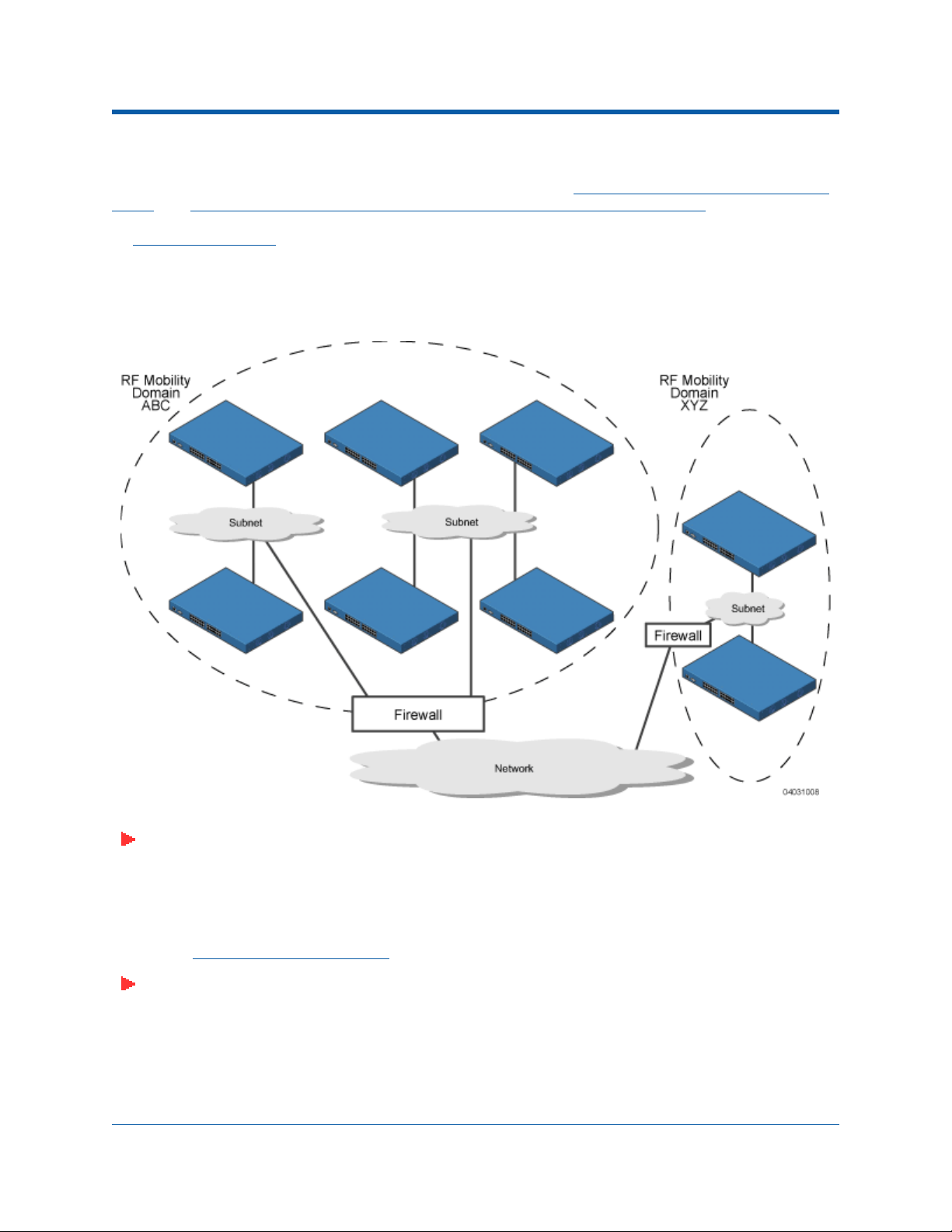
The following figure shows the results of creating Mobility Group Names for two groups of Alcatel OmniAccess Switches and Appliances. The Alcatel OmniAccess Switches and Appliances in the ABC Mobility
Group recognize and communicate with each other through their Alcatel OmniAccess Wireless Access
Points and Alcatel OmniAccess Remote Edge Access Points (OmniAccess 1200R APs) and through their
shared subnets, but the ABC Mobility Group tags the XYZ OmniAccess APs and OmniAccess 1200R APs
as Rogue Access Points
Group do not recognize or communicate with the Alcatel OmniAccess Switches and Appliances in the
ABC Mobility Group. This feature ensures Mobility Group isolation across the network.
. Likewise, the Alcatel OmniAccess Switches and Appliances in the XYZ Mobility
Figure - Typical Alcatel Mobility Group Name Application
Note: Alcatel recommends that you assign one set of VLANs for WLANs and a different set of
VLANs for mobility groups to ensure that Alcatel OmniAccess Switches and Appliances
properly route VLAN traffic.
The Alcatel Mobility Group feature can also be used to limit roaming between different floors, buildings,
or campuses in the same enterprise by assigning different Mobility Group names to different Alcatel
OmniAccess Switches and Appliances within the same wireless network.
If enabled, OmniVista AirView Software
operation is constrained within each Alcatel Mobility Group.
Note: Because the Alcatel OmniAccess Switches and Appliances talk to each other when they
are in the same mobility group, Alcatel recommends that operators do not add physically-separated Alcatel OmniAccess Switches and Appliances to the same static mobility group
to avoid unnecessary traffic on the network.
3/17/04 Alcatel Mobility Group
90-100780-300 Rev 1 Alcatel OmniAccess Wireless Product Guide 13
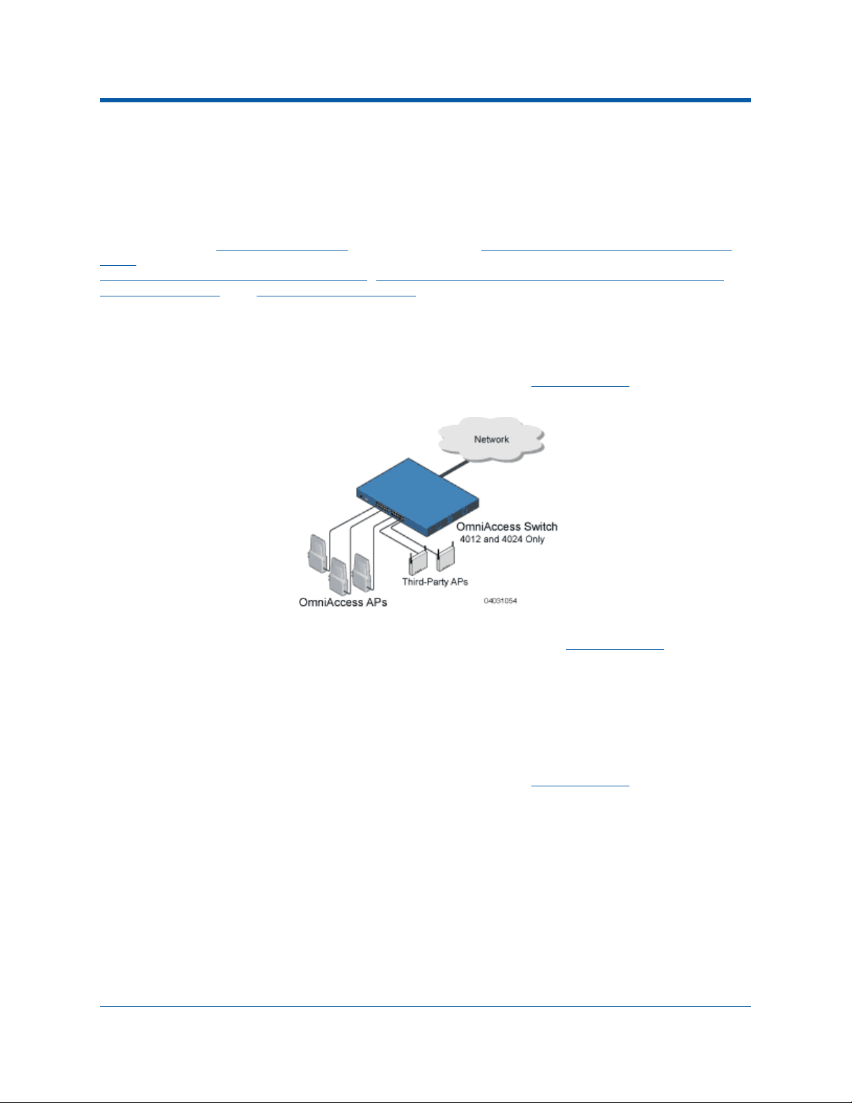
About Alcatel Wired ConnectionsAlcatel Wired Connections
The Alcatel OmniAccess Wireless System components communicate with each other using
industry-standard Ethernet cables and connectors. The following sections contain details of the Alcatel
wired connections.
Between Alcatel OmniAccess Wireless Switches and APsBetween Alcatel OmniAccess Wireless Switches and APs
When operated in Direct-Connect Mode, the 4012 and 4024 Alcatel OmniAccess Switches and Appli-
ances uses standard 802.3 CAT-5 (Category 5) or higher twisted-pair Ethernet cables to connect to
Alcatel OmniAccess Wireless Access Points, Alcatel OmniAccess Remote Edge Access Points (OmniAccess 1200R APs), and Third-Party Access Points. The CAT-5 cable is rated to carry 100 Mbps
(recommended for 802.11a, 802.11a/b, 802.11a/g or 802.11a/b/g installations) or 10 Mbps (only
recommended for low-bandwidth applications and 802.11b-only installations).
The 4012 and 4024 Alcatel OmniAccess Wireless Switches connect to the network using one or more
copper 10/100Base-T cables and/or copper or fiber-optic GigE cables.
Note that the 4102 OmniAccess Wireless Appliances operate only in Appliance Mode
connect directly to any Access Points.
, and do not
When the Alcatel OmniAccess Wireless Switch or Appliance is operated in Appliance Mode, the OmniAccess APs communicate with the Alcatel OmniAccess Switch or Appliance through the network. The
4012 and 4024 Alcatel OmniAccess Wireless Switches connect to the network using one or more copper
10/100Base-T cables and/or copper or fiber-optic GigE cables.
The 4102 OmniAccess Wireless Appliance connects to the network using two fiber-optic GigE cables:
two redundant GigE connections to bypass single network failures. At any given time one of the 4102
OmniAccess Wireless Appliance GigE connections is active and the other is passive. Upon a network
failure, the active connection becomes passive, and the passive connection becomes active.
Note that the 4102 OmniAccess Wireless Appliances only operate in Appliance Mode
connect directly to any Access Points.
3/17/04 Alcatel Wired Connections
90-100780-300 Rev 1 Alcatel OmniAccess Wireless Product Guide 14
, and do not
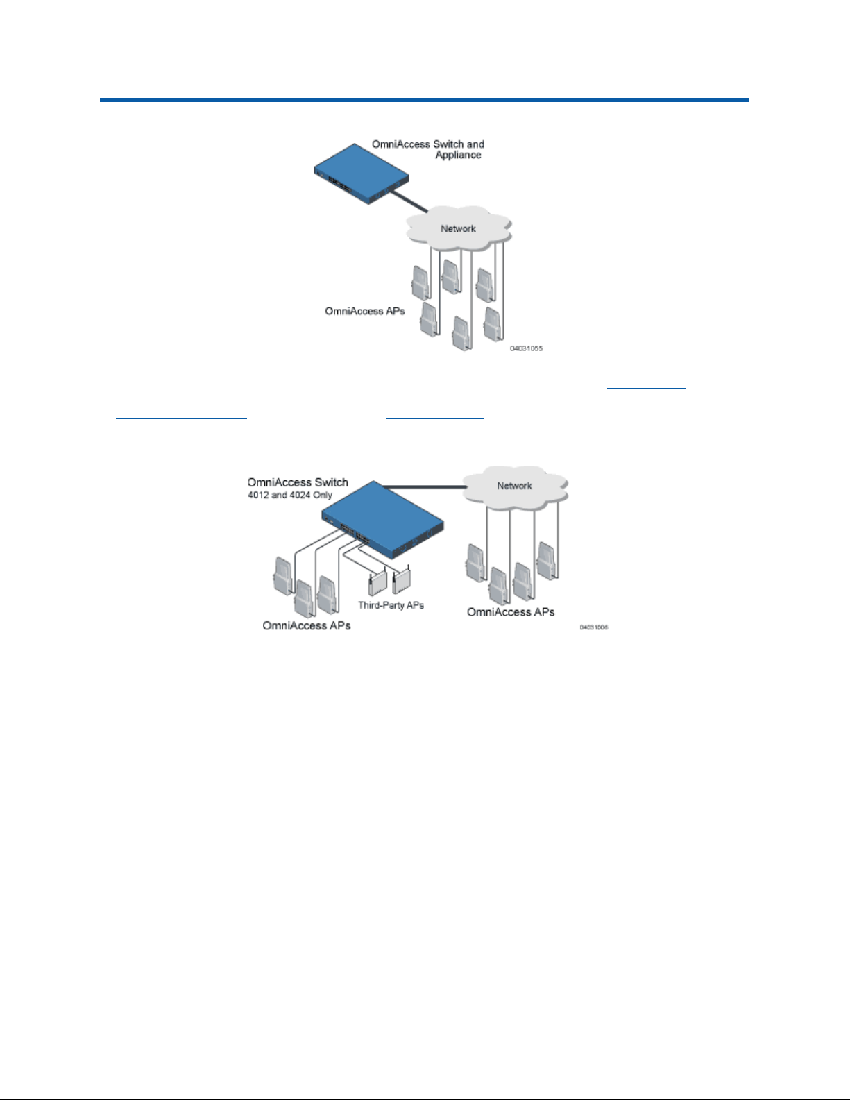
When the 4012 and 4024 Alcatel OmniAccess Wireless Switches are operated in Hybrid Mode, some
OmniAccess APs and third-party APs use the CAT-5 cable to connect to the OmniAccess Wireless Switch
in Direct-Connect Mode
and some connect in Appliance Mode. The OmniAccess Wireless Switch
connects to the network using one or more copper 10/100Base-T cables and/or copper or fiber-optic
GigE cables.
Standard CAT-5 cable supports a 100 m (328 ft.) run between the OmniAccess APs and the OmniAccess
Wireless Switch. This allows a single OmniAccess Wireless Switch to serve OmniAccess APs in multiple
buildings and/or floors in a single building.
The standard CAT-5 cable can also be used to conduct power for the OmniAccess APs from a network
device equipped with Power Over Ethernet
(PoE) capability. This power distribution plan can be used to
reduce the cost of individual AP power supplies and related cabling.
Between Alcatel OmniAccess Switches and Appliances and Other Network DevicesBetween Alcatel OmniAccess Switches and Appliances and Other
Network Devices
The 4012 and 4024 Alcatel OmniAccess Wireless Switches communicate with other Alcatel OmniAccess
Wireless Switches and Appliances or network devices through one or more standard CAT-5 cables
connected to any front-panel port, which supports up to 100 Mbps, and/or through standard rear-panel
Gigabit Ethernet (or GigE) cables, which supports up to 1 Gbps (1,000 Mbps).
The 4102 OmniAccess Wireless Appliance connects to the network using two front-panel fiber-optic
GigE cables: two redundant GigE connections to bypass single network failures. At any given time one
of the 4102 OmniAccess Wireless Appliance GigE connections is active and the other is passive. Upon a
network failure, the active connection becomes passive, and the passive connection becomes active.
3/17/04 Alcatel Wired Connections
90-100780-300 Rev 1 Alcatel OmniAccess Wireless Product Guide 15

About Alcatel WLANsAlcatel WLANs
The Alcatel OmniAccess Wireless System can control up to 16 Wireless LANs for Alcatel OmniAccess
Wireless Access Points and/or Alcatel OmniAccess Remote Edge Access Points (OmniAccess 1200R
APs), plus one WLAN for Third-Party Access Points. Each WLAN has a separate WLAN ID (1 through 17),
a separate WLAN SSID (WLAN Name), and can be assigned unique security policies. A separate WLAN
17 can be created for Third-Party Access Points
Wireless Switch front panel in Direct-Connect Mode.
The OmniAccess APs and OmniAccess 1200R APs broadcast all active Alcatel WLAN SSIDs and enforce
the policies defined for each WLAN, while only the operator-managed third-party APs broadcast the
third-party AP SSID and enforce the operator-defined policies as described in Third-Party Access Points.
Note that many enterprises use different WLANs to separate traffic for different sections or
departments.
connected to a Model 4012 or 4024 OmniAccess
Note: Alcatel recommends that you assign one set of VLANs for WLANs and a different set of
VLANs for mobility groups to ensure that Alcatel OmniAccess Switches and Appliances
properly route VLAN traffic.
If Management over Wireless
OmniAccess Wireless System operator can manage the System across the enabled WLAN using CLI and
Telnet (Command Line Interface
Air Control System Software).
To configure the Alcatel WLANs, refer to Configuring WLANs.
is enabled across an Alcatel OmniAccess Wireless System, the Alcatel
), http/https (Alcatel Web Browser Interface), and SNMP (OmniVista
About Access Control ListsAccess Control Lists
The Alcatel Wireless Operating System allows you to define up to 64 Access Control Lists (ACLs), similar
to standard firewall Access Control Lists. Each ACL can have up to 64 Rules (filters).
Operators can use ACLs to control client access to multiple VPN servers within a given WLAN. If all the
clients on a WLAN must access a single VPN server, use the IPSec/VPN Gateway Passthrough setting in
IPSec Passthrough, WLANs > Edit or Configure <IPaddress> > WLAN Template > Add From Template
section.
After they are defined, the ACLs can be applied to the Management Interface, the AP-Manager Inter-
face, or any of the Operator-Defined Interfaces.
Refer to Access Control Lists > New
Help or Creating Access Control Lists in the Configuring the Alcatel OmniAccess Switch or Appliance
sections for instructions on how to configure the Access Control Lists.
in the Alcatel OmniAccess Wireless System Web Browser Online
About Identity NetworkingIdentity Networking
The Alcatel OmniAccess Wireless Switch and Appliance can have the following parameters applied to all
clients associating with a particular WLAN: QoS, global or Interface-specific DHCP server, Layer 2 and
Layer 3 Security Policies, and default Interface (which includes physical port, VLAN and ACL
assignments).
However, the Alcatel OmniAccess Switch or Appliance can also have individual clients (MAC addresses)
override the preset WLAN parameters by using MAC Filtering or by Allowing AAA Override parameters.
This configuration can be used, for example, to have all company clients log into the corporate WLAN,
and then have clients connect using different QoS, DHCP server, Layer 2 and Layer 3 Security Policies,
and Interface (which includes physical port, VLAN and ACL assignments) settings on a per-MAC Address
basis.
When Alcatel OmniAccess Wireless System operators configure MAC Filtering for a client, they can
assign a different VLAN to the MAC Address, which can be used to have AWOS automatically reroute
the client to the Management Interface
3/17/04 Alcatel WLANs
90-100780-300 Rev 1 Alcatel OmniAccess Wireless Product Guide 16
or any of the Operator-Defined Interfaces, each of which have

their own VLAN, ACL, DHCP server, and physical port assignments. This MAC Filtering can be used as a
coarse version of AAA Override, and normally takes precedence over any AAA (RADIUS or other)
Override.
However, when Allow AAA Override is enabled, the RADIUS (or other AAA) server can alternatively be
configured to return QoS and ACL on a per-MAC Address basis. Allow AAA Override
Override precedence over the MAC Filtering parameters set in the Alcatel OmniAccess Switch or Appliance; if there are no AAA Overrides available for a given MAC Address, the AWOS uses the MAC
Filtering parameters already in the Alcatel OmniAccess Switch or Appliance. This AAA (RADIUS or
other) Override can be used as a finer version of AAA Override, but only takes precedence over MAC
Filtering when Allow AAA Override
Note that in all cases, the Override parameters (Operator-Defined Interface and QoS, for example)
must already be defined in the Alcatel OmniAccess Switch or Appliance configuration.
In all cases, the AWOS will use QoS and ACL provided by the AAA server or MAC Filtering regardless of
the Layer 2 and/or Layer 3 authentication used.
Also note that the AWOS will only move clients from the default Alcatel WLAN VLAN to a different VLAN
when configured for MAC filtering, 802.1X, and/or WPA Layer 2 authentication.
To configure the Alcatel WLANs, refer to Configuring WLANs.
is enabled.
gives the AAA
About Port MirroringPort Mirroring
For troubleshooting, the Alcatel OmniAccess Wireless System operator can Mirror a transmit and
receive data stream through a 4012 or 4024 OmniAccess Wireless Switch client, OmniAccess AP, and/
or third-party AP data stream to another physical port on a 4012 or 4024 OmniAccess Wireless Switch.
Step 1. Set up a Mirror Port on the OmniAccess Wireless Switch.
• In the Command Line Interface (CLI), use the config mirror port command and enable Mirror
Mode for the physical front-panel port.
• In the Web Browser Interface, navigate to the Port > Configure page and enable Mirror Mode
for the physical front-panel port.
• In the ACS interface, navigate to the Monitor Switches > <IPaddress> > Ports > n page and
enable Mirror Mode for the physical front-panel port.
All data to and from mirrored clients, OmniAccess APs, and/or Third-Party APs will now appear on this
port.
Step 2. Once you have set up a front-panel Mirror Port, configure one or more clients, OmniAccess APs,
and/or Third-Party APs to mirror data to the selected Mirror Port.
• Mirror a client by enabling Mirror Mode:
- In the Command Line Interface (CLI), use the config mirror mac command and enable
Mirror Mode for the client.
- In the Web Browser Interface, navigate to the Clients > Detail page and enable Mirror
Mode for the client.
- In the ACS interface, navigate to the Configure Access Point > OmniAccess AP >
<name> and enable Mirror Mode for the client.
• Mirror an OmniAccess AP by enabling Mirror Mode:
- In the CLI, navigate to the config mirror ap command and enable Mirror Mode for the
OmniAccess AP.
- In the Web Browser Interface, use the OmniAccess APs > Details page and enable
Mirror Mode for the OmniAccess AP.
3/17/04 Port Mirroring
90-100780-300 Rev 1 Alcatel OmniAccess Wireless Product Guide 17

- In the ACS interface, navigate to the Configure <IPaddress> > OmniAccess AP and
enable Mirror Mode for the OmniAccess AP.
• Mirror any Third-Party AP (up to 100 simultaneous clients) by enabling Mirror Mode:
- In the CLI, use the config mirror foreignap command and enable Mirror Mode for the
Third-Party AP port on the OmniAccess Wireless Switch.
- In the Web Browser Interface, navigate to the Third-Party APs > Edit page and enable
Mirror Mode for the Third-Party AP port on the OmniAccess Wireless Switch.
- In the ACS interface, navigate to the Configure <IPaddress> > Connected Third Party
AP and enable Mirror Mode for the Third-Party AP port on the OmniAccess Wireless
Switch.
Note: If the Third-Party AP has more than 100 simultaneous clients, you will have to enable
Mirror Mode individually for the remaining clients.
About File TransfersTransferring Files
The Alcatel OmniAccess Wireless System operator can upload and download Alcatel Wireless Operating
System code, configuration, and certificate files to and from an Alcatel OmniAccess Wireless Switch or
Appliance using CLI commands, Alcatel Web Browser Interface commands, or OmniVista Air Control
System Software (ACS Software) commands.
• To use CLI commands, refer to Transferring Files To and From an Alcatel OmniAccess Switch or
Appliance.
• To use the Web Browser Interface, go to Using the Alcatel Web Browser Interface.
• To use ACS Software Server commands, continue with Using the OmniVista Air Control System
Software.
About Power Over EthernetPower Over Ethernet
Alcatel OmniAccess Wireless Switches and OmniAccess APs support 802.3af-compatible Power over
Ethernet (PoE), which can reduce the cost of discrete power supplies, additional wiring, conduits,
outlets, and installer time. PoE also frees installers from having to mount Alcatel OmniAccess Wireless
Access Points, Alcatel OmniAccess Remote Edge Access Points (OmniAccess 1200R APs) or other
powered equipment near AC outlets, providing greater flexibility in positioning OmniAccess APs and
OmniAccess 1200R APs for maximum coverage.
When you are using PoE, the installer runs a single CAT-5 cable from each OmniAccess AP or OmniAccess AP 1200R to the PoE-equipped Alcatel OmniAccess Switches or Appliances or other network
elements, to a PoE power hub, or to a Alcatel Single-Line PoE Injector, described in OmniAccess AP
Models. When the PoE equipment determines that the OmniAccess AP or OmniAccess AP 1200R is
PoE-enabled, it sends 48 VDC over the unused pairs in the Ethernet cable to power the OmniAccess AP
or OmniAccess AP 1200R.
The PoE cable length is limited by the 100Base-T or 10Base-T specification to 100 m or 200 m,
respectively.
Note: OmniAccess APs and OmniAccess 1200R APs can receive power from the OmniAccess
Wireless Switch or any other network device conforming to the IEEE 802.3af standard.
Note: Each OmniAccess AP and OmniAccess AP 1200R can alternatively receive power from an
OmniAccess AP External Power Supply.
The OmniAccess Wireless Switch can be ordered with or without PoE, as required. It can be ordered
with internal PoE, an external third-party PoE hub, or an Alcatel Single-Line PoE Injector. Contact
Alcatel for recommended external PoE equipment.
3/17/04 Transferring Files
90-100780-300 Rev 1 Alcatel OmniAccess Wireless Product Guide 18

About Alcatel OmniAccess Switches and AppliancesAlcatel OmniAccess Switches and Appliances
The Alcatel OmniAccess Wireless Switch and Appliance are enterprise-class high-performance wireless
switching platforms that support 802.11a and 802.11b/802.11g protocols. They operate under control
of the Alcatel Wireless Operating System, and include the OmniAccess Wireless Switched Architecture,
which results in an Alcatel OmniAccess Wireless System that can automatically adjust to real-time
changes in the 802.11 RF environment. The Alcatel OmniAccess Switches and Appliances are built
around high-performance network and security hardware, resulting in highly reliable 802.11 enterprise
networks with unparalleled security. Also see:
• 4012 and 4024 OmniAccess Wireless Switch Models
• 4102 OmniAccess Wireless Appliance Model
• Alcatel OmniAccess Switch and Appliance Features
• Alcatel OmniAccess Switch and Appliance Model Numbers
• Direct-Connect Mode
• Appliance Mode
• Hybrid Mode
• Distribution System Ports
• Management Interface
• AP-Manager Interface
• Operator-Defined Interfaces
• Virtual Interface
• Service Port
• Service-Port Interface
• Startup Wizard
• Alcatel OmniAccess Switch and Appliance Memory
• Alcatel OmniAccess Switch and Appliance Failover Protection
• Network Connection to an Alcatel OmniAccess Switch or Appliance
• Enhanced Security Module
• Alcatel Wired Connections
• Alcatel OmniAccess Wireless Access Points
• Alcatel OmniAccess Remote Edge Access Points (OmniAccess 1200R APs)
• Alcatel WLANs
• Identity Networking
• Port Mirroring
• Configuring the Alcatel OmniAccess Switch or Appliance
• Transferring Files To and From an Alcatel OmniAccess Switch or Appliance
• Updating the Alcatel Wireless Operating System Software
• Clearing Configurations
• Resetting the Alcatel OmniAccess Switch or Appliance
3/17/04 Alcatel OmniAccess Switches and Appliances
90-100780-300 Rev 1 Alcatel OmniAccess Wireless Product Guide 19
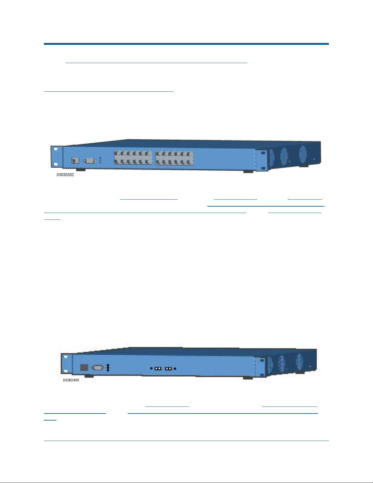
• Alcatel OmniAccess Switch and Appliance Quick Installation Guide
4012 and 4024 OmniAccess Wireless Switch Models4012 and 4024 OmniAccess Wireless Switch Models
About the Alcatel OmniAccess Wireless System gives a comprehensive overview of the Alcatel Omni-
Access Wireless System and the place of the Alcatel OmniAccess Wireless Switches and Appliances in
that system. The following figure shows the 4024 OmniAccess Wireless Switch. The 4012 OmniAccess
Wireless Switch is similar to the 4024, but has 12 front-panel RJ-45 jacks instead of 24.
Figure - 4024 OmniAccess Wireless Switch
The 4012 and 4024 Alcatel OmniAccess Wireless Switches are one-unit high 802.11 Wireless Switches
that communicate directly (Direct-Connect Mode
with up to 24 (Model 4024) or 12 (Model 4012) associated Alcatel OmniAccess Wireless Access Points
Alcatel OmniAccess Remote Edge Access Points (OmniAccess 1200R APs) and/or Third-Party Access
Points. The 4012 and 4024 Alcatel OmniAccess Wireless Switches can be factory- or field-equipped with
an Enhanced Security Module (Crypto Card) to support VPN, IPSec and other processor-intensive tasks,
and with one 1000Base-T (copper) or a single- or dual-1000Base-SX (fiber-optic) Network Adaptor
Module to allow the OmniAccess Wireless Switch to communicate with the network at GigE (Gigabit
Ethernet) speeds.
The two redundant GigE connections on the dual-1000Base-SX (fiber-optic) Network Adaptor Module
allow the OmniAccess Wireless Switch to bypass single network failures. At any given time one of the
dual-1000Base-SX (fiber-optic) Network Adaptor Module GigE connections is active and the other is
passive. Upon a network failure, the active connection becomes passive, and the passive connection
becomes active.
), indirectly (Appliance Mode), or both (Hybrid Mode)
,
4102 OmniAccess Wireless Appliance Model4102 OmniAccess Wireless Appliance Model
The following figure shows the 4102 OmniAccess Wireless Appliance, which has two redundant
front-panel SX/LC jacks.
Figure - 4102 OmniAccess Wireless Appliance
The 4102 OmniAccess Wireless Appliances are one-unit high 802.11 Wireless Appliances that communicate indirectly through the network (Appliance Mode
Wireless Access Points and/or Alcatel OmniAccess Remote Edge Access Points (OmniAccess 1200R
APs). The 4102 OmniAccess Wireless Appliances can be factory-ordered with an Enhanced Security
Module (Crypto Card) to support VPN, IPSec and other processor-intensive tasks, and with two (4102)
3/17/04 4012 and 4024 OmniAccess Wireless Switch Models
90-100780-300 Rev 1 Alcatel OmniAccess Wireless Product Guide 20
) with up to 36 associated Alcatel OmniAccess

1000Base-SX network connectors to allow the OmniAccess Wireless Appliance to communicate with the
network at GigE (Gigabit Ethernet) speeds.
The two redundant GigE connections on the 4102 allow the OmniAccess Wireless Appliance to bypass
single network failures. At any given time one of the 4102 OmniAccess Wireless Appliance GigE connections is active and the other is passive. Upon a network failure, the active connection becomes passive,
and the passive connection becomes active.
Alcatel OmniAccess Switch and Appliance FeaturesAlcatel OmniAccess Switch and Appliance Features
Because Alcatel OmniAccess Wireless Switches and Appliances perform most of the processes normally
performed by SOHO Access Points, it can reduce the amount of inter-AP traffic on the wired backbone
network when used in Direct-Connect Mode. When operated in Appliance Mode, Alcatel OmniAccess
Switches and Appliances connect to the associated OmniAccess APs and Alcatel OmniAccess Remote
Edge Access Points (OmniAccess 1200R APs) through the network. When deployed in Hybrid Mode
Alcatel OmniAccess Wireless Switches simultaneously communicate with their associated APs through
their front-panel ports as well as through the network.
Note that the 4102 OmniAccess Wireless Appliances are designed to operate exclusively in Appliance
Mode. As such, they are limited to controlling Alcatel OmniAccess Wireless Access Points and Alcatel
OmniAccess Remote Edge Access Points (OmniAccess 1200R APs).
After each Alcatel OmniAccess Switch or Appliance is installed and configured, the Alcatel Wireless
Operating System OmniVista AirView Software is activated, and the Alcatel Wireless Operating System
manages and controls associated OmniAccess APs, OmniAccess 1200R APs and/or third-party APs
(Direct-Connect Mode
addresses. This information allows all Alcatel OmniAccess Switches and Appliances within each Alcatel
Mobility Group to constantly monitor and dynamically adjust the RF environment, maximizing perfor-
mance, minimizing interference, and distributing the client load.
When operated in Direct-Connect Mode, the 4012 or 4024 Alcatel OmniAccess Wireless Switches
communicate directly with OmniAccess APs, OmniAccess 1200R APs and third-party APs via 10/
100Base-T Ethernet cables.
When operated in Appliance Mode
cate with OmniAccess APs and OmniAccess 1200R APs via 10/100Base-T Ethernet or 1000Base-T or
1000Base-SX cables through the network. Note that the optional dual-1000Base-SX module uses two
redundant GigE connections to bypass single network failures. At any given time one of the
dual-1000Base-SX module GigE connections is active and the other is passive. Upon a network failure,
the active connection becomes passive, and the passive connection becomes active.
When operated in Appliance Mode
Access APs and OmniAccess 1200R APs via 1000Base-SX cables through the network. Note that the
4102 OmniAccess Wireless Appliance uses two redundant GigE connections to bypass single network
failures. At any given time one of the 4102 OmniAccess Wireless Appliance GigE connections is active
and the other is passive. Upon a network failure, the active connection becomes passive, and the
passive connection becomes active.
The 4012 or 4024 Alcatel OmniAccess Wireless Switches communicate with network via one or more
front-panel 10/100Base-T Ethernet ports and/or 1000Base-T or 1000Base-SX Network ports. The 4102
OmniAccess Wireless Appliances communicate with network via two (4102) 1000Base-SX Network
Ports: the 4102 OmniAccess Wireless Appliance uses two redundant GigE connections to bypass single
network failures.
Regardless of operating mode, the network operator can control the Alcatel OmniAccess Switches and
Appliances with the following Alcatel Wireless Operating System device servicing interfaces:
only), with information about their relative positions, IP Addresses, and MAC
, the 4012 and 4024 Alcatel OmniAccess Wireless Switches communi-
, the 4102 OmniAccess Wireless Appliances communicate with Omni-
• With optional OmniVista Air Control System Software (ACS Software Server) inband or
out-of-band via a front-panel 10/100Base-T Service port (Service Interface), or via the network
(Management Interface).
,
3/17/04 Alcatel OmniAccess Switch and Appliance Features
90-100780-300 Rev 1 Alcatel OmniAccess Wireless Product Guide 21

• With the built-in Command Line Interface via a serial RS232-C Console Port (direct connection),
or via the network (Telnet connection).
• With the built-in Alcatel Web Browser Interface via a dedicated 10/100Base-T Service port
(recommended), or via the network, using either http or https (http + SSL).
Refer to the following for more information about the Alcatel OmniAccess Switches and Appliances:
• 4012 and 4024 OmniAccess Wireless Switch Models
• 4102 OmniAccess Wireless Appliance Model
• Alcatel OmniAccess Switch and Appliance Model Numbers
• Direct-Connect Mode
• Appliance Mode
• Hybrid Mode
• Distribution System Ports
• Management Interface
• AP-Manager Interface
• Operator-Defined Interfaces
• Virtual Interface
• Service Port
• Service-Port Interface
• Startup Wizard
• Alcatel OmniAccess Switch and Appliance Memory
• Alcatel OmniAccess Switch and Appliance Failover Protection
• Network Connection to an Alcatel OmniAccess Switch or Appliance
• Enhanced Security Module
• Alcatel Wired Connections
• Alcatel OmniAccess Wireless Access Points
• Alcatel OmniAccess Remote Edge Access Points (OmniAccess 1200R APs)
• Alcatel Wired Connections
• Alcatel WLANs
• Port Mirroring
• Configuring the Alcatel OmniAccess Switch or Appliance
• Transferring Files To and From an Alcatel OmniAccess Switch or Appliance
• Updating the Alcatel Wireless Operating System Software
• Clearing Configurations
• Resetting the Alcatel OmniAccess Switch or Appliance
• Alcatel OmniAccess Switch and Appliance Quick Installation Guide
3/17/04 Alcatel OmniAccess Switch and Appliance Features
90-100780-300 Rev 1 Alcatel OmniAccess Wireless Product Guide 22

Alcatel OmniAccess Switch and Appliance Model NumbersAlcatel OmniAccess Switch and Appliance Model Numbe rs
The Alcatel OmniAccess Wireless Switch and Appliance models are as follows:
• OAW-4012 - 12-Port OmniAccess Wireless Switch with an optional 1000Base-T or
1000Base-SX/LC Network Adapter, used in Direct-Connect Mode
Mode.
• OAW-4024 - 24-Port OmniAccess Wireless Switch with an optional 1000Base-T or
1000Base-SX/LC Network Adapter, used in Direct-Connect Mode
Mode.
• OAW-4012-DWP - Twelve-Port OmniAccess Wireless Switch with built-in PoE Hub and an
optional 1000Base-T or 1000Base-SX/LC Network Adapter, used in Direct-Connect Mode
Appliance Mode, and Hybrid Mode.
• OAW-4024-DWP - 24-Port OmniAccess Wireless Switch with built-in PoE Hub and an optional
1000Base-T or 1000Base-SX/LC Network Adapter, used in Direct-Connect Mode
Mode, and Hybrid Mode.
• (UNUSED COMPONENT) - 36-Port OmniAccess Wireless Appliance with one 1000Base-SX/LC
Network Adapter, used only in Appliance Mode.
• OAW-4102 - 36-Port OmniAccess Wireless Appliance with one 1000Base-SX/LC Network
Adapter, used only in Appliance Mode. The 4102 OmniAccess Wireless Appliance uses two
redundant GigE connections to bypass single network failures. That is, at any given time one of
the 4102 OmniAccess Wireless Appliance GigE connections is active and the other is passive.
Upon a network failure, the active connection becomes passive, and the passive connection
becomes active.
Note that all Alcatel OmniAccess Switch and Appliance models come from the factory with 19-inch EIA
equipment rack flush-mount ears and tabletop mounting feet.
The following upgrade modules are also available:
• OAW-ESM - Enhanced Security Module: Supports VPN, IPSec and other processor-intensive
security options. This is a factory-orderable and field-installable option for all Alcatel
OmniAccess Switches and Appliances.
• OAW-GT - 1000Base-T Network Adapter Module: Supports 1000Base-T connections to the
network. This is a factory-orderable and field-installable option for 4012 and 4024 Alcatel
OmniAccess Wireless Switches.
• OAW-GSX - Single-1000Base-SX Network Adapter Module: Supports 1000Base-SX connections
to the network. This is a factory-orderable and field-installable option for 4012 and 4024 Alcatel
OmniAccess Wireless Switches.
• OAW-GSX2 - Dual-1000Base-SX Network Adapter Module: Supports two 1000Base-SX connec-
tions to the network. This is a factory-orderable and field-installable option for 4012 and 4024
Alcatel OmniAccess Wireless Switches. The dual-1000Base-SX module uses two redundant GigE
connections to bypass single network failures. At any given time one of the dual-1000Base-SX
module GigE connections is active and the other is passive. Upon a network failure, the active
connection becomes passive, and the passive connection becomes active.
, Appliance Mode, and Hybrid
, Appliance Mode, and Hybrid
,
, Appliance
OmniAccess Wireless Switch Direct-Connect ModeDirect-Connect Mode
The 4012 and 4024 Alcatel OmniAccess Wireless Switches can be operated in Direct-Connect Mode, in
Appliance Mode, or in Hybrid Mode, either in ISO Data Link Layer 2 or Network Layer 3 (Layer 2 and
Layer 3 Operation). In Direct-Connect Mode, the Alcatel OmniAccess Wireless Switches are directly
connected to up to 24 (Model 4024) or up to 12 (Model 4012) OmniAccess APs and/or third-party APs
3/17/04 Alcatel OmniAccess Switch and Appliance Model Numbers
90-100780-300 Rev 1 Alcatel OmniAccess Wireless Product Guide 23

over CAT-5 or higher Ethernet cabling. The benefit of this mode is that the Alcatel OmniAccess Wireless
Switches can provide Power Over Ethernet.
The following figure shows an OmniAccess Wireless Switch in the Direct-Connect Mode, and the rest of
the section describes the 4012 and 4024 OmniAccess Wireless Switch connections to the network.
Figure - OmniAccess Wireless Switch Direct-Connect Mode
The OmniAccess Wireless Switch filters packets and forwards them between LAN segments. When the
OmniAccess Wireless Switch is operated in Direct-Connect Mode, it transmits data between all
connected OmniAccess APs and third-party APs, which results in fewer packets being placed on the
backbone network.
The 4012 and 4024 Alcatel OmniAccess Wireless Switches communicate with the backbone network via
a 1000Base-T or 1000Base-SX Network Port, or via any front-panel 10/100Base-T Ethernet port as
described in the Network Connection to an Alcatel OmniAccess Switch or Appliance
The Alcatel OmniAccess Wireless Switch or Appliance uses industry-standard SNMP protocol to communicate with the OmniVista Air Control System Software, and communicates with Alcatel Wireless
Operating System device servicing interfaces as follows:
section.
• With an optional ACS Software Server or other Alcatel Wireless Operating System Service
Interface, either directly connected or through an out-of-band Alcatel Wireless Operating
System Service Network, or via a dedicated 10/100Base-T Service Port.
• With an optional VT-100 CLI console via a serial RS232-C Console Port.
Note: Alcatel recommends that you not use the network for your Alcatel Wireless Operating
System device service, because a service outage on your network means that you have no
dedicated path to the OmniAccess Wireless Switch.
The OmniAccess Wireless Switch can be equipped with built-in Power Over Ethernet
external PoE hub, or an Alcatel Single Inline Power over Ethernet Injector which allows associated
OmniAccess APs, Alcatel OmniAccess Remote Edge Access Points, and/or third-party APs to receive
power over the CAT-5 Ethernet cabling.
circuitry, an
Alcatel OmniAccess Switches and Appliances in Appliance ModeAppliance Mode
All 4012 and 4024 Alcatel OmniAccess Wireless Switches and 4102 OmniAccess Wireless Appliances can
be operated in Appliance Mode. (The 4012 and 4024 Alcatel OmniAccess Wireless Switches can also be
operated in Direct-Connect Mode
or Appliance communicates indirectly with up to 36 (Model 4102), up to 24 (Model 4024) or up to 12
(Model 4012) associated OmniAccess APs and Alcatel OmniAccess Remote Edge Access Points through
the network. The following figure shows an Alcatel OmniAccess Switch or Appliance in Appliance Mode.
3/17/04 Appliance Mode
90-100780-300 Rev 1 Alcatel OmniAccess Wireless Product Guide 24
or Hybrid Mode.) In Appliance Mode, the Alcatel OmniAccess Switch

Figure - Alcatel OmniAccess Wireless Switch or Appliance Deployed in Appliance Mode
The Alcatel OmniAccess Switch or Appliance communicates with the network using one of the interfaces
described in the Network Connection to an Alcatel OmniAccess Switch or Appliance
section.
OmniAccess Wireless Switch Hybrid ModeHybrid Mode
The 4012 and 4024 Alcatel OmniAccess Wireless Switches can be operated in Hybrid Mode, Appliance
Mode or Direct-Connect Mode. In Hybrid Mode, the OmniAccess Wireless Switch communicates directly
and indirectly with up to 24 (Model 4024) or up to 12 (Model 4012) associated OmniAccess APs, Alcatel
OmniAccess Remote Edge Access Points, and/or third-party APs over Ethernet cabling, and with associated OmniAccess APs and Alcatel OmniAccess Remote Edge Access Points through the network. The
following figure shows an OmniAccess Wireless Switch in Hybrid Mode.
Figure - OmniAccess Wireless Switch Deployed in Hybrid Mode
The OmniAccess Wireless Switch communicates with the network using one of the interfaces described
in the Network Connection to an Alcatel OmniAccess Switch or Appliance
section.
About Distribution System PortsDistribution System Ports
A Distribution System (DS) port is a physical port (see Alcatel Wired Connections) through which the
Alcatel OmniAccess Switch or Appliance talks to the network and other Access Points. DS Ports are
where packets are exchanged between the Alcatel OmniAccess Wireless System WLANs and the rest of
the network. The DS Ports can also be used to communicate with OmniAccess APs in Appliance Mode or
Hybrid Mode.
3/17/04 Hybrid Mode
90-100780-300 Rev 1 Alcatel OmniAccess Wireless Product Guide 25

• The 4102 OmniAccess Wireless Appliance supports a single Distribution System port because it
has two redundant 1000Base-SX physical ports that must connect to the same subnet.
• The OmniAccess Wireless Switch can have as many Distribution System ports as it has 10/100/
1000Base-T/-SX physical ports, except when the Switch is equipped with a dual-port
1000Base-SX Network Adapter Module. When the Switch is equipped with a dual-port
1000Base-SX Network Adapter Module, the Network Adapter Module’s two redundant physical
ports must connect to the same subnet.
Note: The Distribution System Port cannot be assigned to the dedicated Alcatel OmniAccess
Switch or Appliance front-panel Service Port.
As described in Layer 2 and Layer 3 Operation, when the LWAPP communications are set to Layer 2
(same subnet) operation, the Distribution System must have one Management Interface to control all
inter-Alcatel OmniAccess Switch and Appliance and all Alcatel OmniAccess Switch and Appliance-to-AP
communications, regardless of the number of physical Distribution System ports.
Also as described in Layer 2 and Layer 3 Operation
Layer 3 (different subnet) operation, the Distribution System must have one Management Interface to
control all inter-Alcatel OmniAccess Switch and Appliance communications, and must have one
AP-Manager Interface
regardless of the number of physical Distribution System ports.
Each physical Distribution System port can also have between one and 64 Operator-Defined Interfaces
assigned to it. Each Operator-Defined Interface is individually configured, and allows VLAN communications to exist on the Distribution System port(s).
Refer to the Configuring the Alcatel OmniAccess Switch or Appliance section for configuration
instructions.
to control all Alcatel OmniAccess Switch and Appliance-to-AP communications,
, when the LWAPP communications are set to
About the Management InterfaceManagement Interface
The logical Management Interface controls Layer 2 communications between Alcatel OmniAccess
Wireless Switches and Appliances, OmniAccess APs, Alcatel OmniAccess Remote Edge Access Points
(OmniAccess 1200R APs), and Third-Party Access Points
The Management Interface is assigned to one physical port (Alcatel Wired Connections
it communicates with other network devices and other access points. However, the Management
Interface can also communicate through all other physical ports except the front-panel Service Port
follows:
• Sends messages through the Layer 2 network to autodiscover and communicate with other
Alcatel OmniAccess Switches and Appliances through all physical ports except the front-panel
Service Port
.
• Listens across the Layer 2 network for OmniAccess AP LWAPP polling messages to
autodiscover, associate with, and communicate with as many OmniAccess APs as it can.
Note: Should an OmniAccess Wireless Appliance or OmniAccess Wireless Switch in Appliance
Mode fail, its dropped OmniAccess APs poll the network for another Alcatel OmniAccess Switch
or Appliance. When an online Alcatel OmniAccess Switch or Appliance has any remaining AP
ports, the Management Interface listens to the network for OmniAccess AP polling messages
to autodiscover, associate with, and communicate with as many OmniAccess APs as it can.
Refer to the Alcatel OmniAccess Switch and Appliance Failover Protection
information.
Note: The Management Interface cannot be assigned to the dedicated Alcatel OmniAccess
Switch or Appliance front-panel Service Port.
The Management Interface uses the burned-in Alcatel OmniAccess Switch or Appliance Distribution
System MAC address, and must be configured for the following:
.
), through which
section for more
as
3/17/04 Management Interface
90-100780-300 Rev 1 Alcatel OmniAccess Wireless Product Guide 26

• VLAN assignment.
• Fixed IP Address, IP netmask, and default gateway.
• Physical port assignment.
• Primary and Secondary DHCP Servers.
• Access Control List, if required.
Refer to the Configuring the Alcatel OmniAccess Switch or Appliance section for configuration
instructions.
About the AP-Manager InterfaceAP-Manager Interface
The logical AP-Manager Interface controls Layer 3 communications between Alcatel OmniAccess
Wireless Switches and Appliances, OmniAccess APs, and Alcatel OmniAccess Remote Edge Access
Points (OmniAccess 1200R APs).
Note: The AP-Manager Interface does not control communications with Third-Party Access
Points, because the third-party APs must be connected directly to the 4012 or 4024 Omni-
Access Wireless Switch front-panel ports (Layer 2 operation).
The AP-Manager Interface is assigned to one physical port (Alcatel Wired Connections), and can be on
the same subnet and physical port as the Management Interface. The AP-Manager Interface can
communicate through any physical port except the front-panel Service Port
• Sends Layer 3 messages through the network to autodiscover and communicate with other
Alcatel OmniAccess Switches and Appliances.
• Listens across the network for Layer 3 OmniAccess AP and OmniAccess AP 1200R LWAPP
polling messages to autodiscover, associate with, and communicate with as many OmniAccess
APs and OmniAccess 1200R APs as it can.
Note: Should an OmniAccess Wireless Appliance or OmniAccess Wireless Switch in Appliance
Mode fail, its dropped OmniAccess APs and OmniAccess 1200R APs poll the network for
another Alcatel OmniAccess Switch or Appliance. When an online Alcatel OmniAccess Switch
or Appliance has any remaining AP ports, the AP-Manager Interface listens to the network for
OmniAccess AP and OmniAccess AP 1200R polling messages to autodiscover, associate with,
and communicate with as many OmniAccess APs and OmniAccess 1200R APs as it can. Refer
to the Alcatel OmniAccess Switch and Appliance Failover Protection
information.
Note: The AP-Manager Interface cannot be assigned to the dedicated Alcatel OmniAccess
Switch or Appliance front-panel Service Port.
The AP-Manager Interface must be configured for the following:
• VLAN assignment.
as follows:
section for more
• Fixed IP Address (must be different than the Management Interface IP address, but must be on
the same subnet as the Management Interface), IP netmask, and default gateway.
• Physical port assignment.
• Primary and Secondary DHCP Servers.
• Access Control List, if required.
Refer to the Configuring the Alcatel OmniAccess Switch or Appliance
instructions.
3/17/04 AP-Manager Interface
90-100780-300 Rev 1 Alcatel OmniAccess Wireless Product Guide 27
section for configuration

About Operator-Defined InterfacesOperator-Defined Interfaces
Each Alcatel OmniAccess Switch and Appliance can support up to 64 Operator-Defined Interfaces. Each
Operator-Defined Interface controls VLAN and other communications between Alcatel OmniAccess
Wireless Switches and Appliances and all other network devices connected to an individual physical
port. Between one and 64 Operator-Defined Interfaces can be assigned to Alcatel WLANs
Distribution System Ports
, the Layer 2 Management Interface, and the Layer 3 AP-Manager Interface.
, physical
Note: Operator-Defined Interfaces cannot be assigned to the dedicated Alcatel OmniAccess
Switch or Appliance front-panel Service Port.
CAUTION: Operator-Defined Interface names cannot have spaces in them. If an Oper-
ator-Defined Interface name contains a space, you may not be able to edit its configuration
using the Command Line Interface
Each Operator-Defined Interface must be configured for the following:
.
• VLAN number.
• Fixed IP Address, IP netmask, and default gateway.
• Physical port assignment.
• Primary and Secondary DHCP Servers.
• Access Control List, if required.
Refer to the Configuring the Alcatel OmniAccess Switch or Appliance
instructions.
section for configuration
About the Virtual InterfaceVirtual Interface
The Virtual Interface controls Layer 3 Security and Mobility manager communications for Alcatel OmniAccess Wireless Switches and Appliances. It maintains the DNS Gateway hostname used by Layer 3
Security and Mobility managers to verify the source of certificates when Layer 3 Web Auth is enabled.
The Virtual Interface must be configured for the following:
• Any fictitious, unassigned, unused Gateway IP Address.
• DNS Gateway Host Name.
Refer to the Configuring the Alcatel OmniAccess Switch or Appliance
instructions.
section for configuration
About the Service PortService Port
The physical Service port on the Alcatel OmniAccess Wireless Switch or Appliance front panel is a 10/
100Base-T Ethernet port dedicated to Alcatel Wireless Operating System device service, and was
formerly known as the Management port. The Service Port is controlled by the Service-Port Interface
The Service Port is configured with an IP Address, subnet mask, and IP assignment protocol different
from the Management Interface. This allows the operator to manage the Alcatel OmniAccess Switch or
Appliance directly or through a dedicated Alcatel Wireless Operating System service network, such as
10.1.2.x, which can ensure Alcatel Wireless Operating System device service access during network
downtime.
Alcatel created the Service port to remove the Alcatel OmniAccess Wireless System device service from
the network data stream to improve security and to provide a faster service connection.
Note that you cannot assign a Gateway to the Service port, so the port is not routable, unlike the other
front-panel 10/100Base-T ports. However, you can set up dedicated routes to network management
devices.
3/17/04 Operator-Defined Interfaces
90-100780-300 Rev 1 Alcatel OmniAccess Wireless Product Guide 28
.

Also note that the Service Port is not auto-sensing, unlike the other front-panel 10/100Base-T ports:
you must use the correct straight-through or crossover Ethernet cable to communicate with the Service
Port.
Refer to the Configuring Other Ports and Parameters for information on how to configure the Service
Port.
About the Service-Port InterfaceService-Port Interface
The Service-Port Interface controls communications through the dedicated Alcatel OmniAccess Switch
or Appliance front-panel Service Port
.
Note: The Service-Port Interface can only be assigned to the dedicated Alcatel OmniAccess
Switch or Appliance front-panel Service Port.
The Service-Port Interface uses the burned-in Alcatel OmniAccess Switch or Appliance Service Port MAC
address, and must be configured for the following:
• Whether or not DHCP Protocol is activated.
• IP Address and IP netmask.
Refer to the Configuring the Alcatel OmniAccess Switch or Appliance section for configuration
instructions.
About the Startup WizardStartup Wizard
When an Alcatel OmniAccess Wireless Switch or Appliance is powered up with a new factory Alcatel
Wireless Operating System software load or after being reset to factory defaults, the bootup script runs
the Startup Wizard, which prompts the installer for initial configuration. The Startup Wizard:
• Ensures that the Alcatel OmniAccess Switch or Appliance has a System Name, up to
32 characters.
• Adds an Administrative User Name and Password, each up to 24 characters.
• Ensures that the Alcatel OmniAccess Switch or Appliance can communicate with the CLI, ACS
Software, or Web Browser Alcatel Wireless Operating System device service interfaces (either
directly or indirectly) through the Service Port
(none or DHCP), and if ‘none’, IP Address and netmask. If you do not want to use the Service
port, enter 0.0.0.0 for the IP Address and netmask; this disables the Service Port.
Note: Alcatel recommends that you not use the network for your Alcatel Wireless Operating
System management, because a service outage on your network means that you have no
dedicated path to the OmniAccess Wireless Switch.
• Ensures that the Alcatel OmniAccess Switch or Appliance can communicate with the network
(802.11 Distribution System) through the Management Interface by collecting a valid static IP
Address, netmask, default router IP address, VLAN identifier, and physical port assignment.
• Prompts for the IP address of the DHCP server used to supply IP addresses to clients, the
Alcatel OmniAccess Switch or Appliance Management Interface, and optionally to the Service
Port Interface.
• Asks for the LWAPP Transport Mode, described in Layer 2 and Layer 3 Operation.
by accepting a valid IP configuration protocol
• Collects the Virtual Gateway IP Address; any fictitious, unassigned IP address (such as 1.1.1.1)
to be used by Layer 3 Security and Mobility managers.
• Allows you to enter the Alcatel Mobility Group (RF Group) Name.
• Collects the WLAN 1 802.11 SSID, or Network Name.
3/17/04 Service-Port Interface
90-100780-300 Rev 1 Alcatel OmniAccess Wireless Product Guide 29

• Asks you to define whether or not clients can use static IP addresses. Yes = more convenient,
but lower security (session can be hijacked), clients can supply their own IP Address, better for
devices that cannot use DHCP. No = less convenient, higher security, clients must DHCP for an
IP Address, works well for Windows XP devices.
• If you want to configure a RADIUS server from the Startup Wizard, the RADIUS server IP
address, communication port, and Secret.
• Collects the Country Code. (Refer to Configuring the Alcatel OmniAccess Switch or Appliance
and Alcatel OmniAccess Wireless System Supported Regulatory Domains.
• Enables and/or disables the 802.11a, 802.11b and 802.11g OmniAccess AP networks.
• Enables or disables OmniVista AirView Software.
To use the Startup Wizard, refer to Using the Startup Wizard
.
About Alcatel OmniAccess Switch and Appliance MemoryAlcatel OmniAccess Switch and Appliance Memory
The Alcatel OmniAccess Wireless Switches and Appliances contain two kinds of memory: volatile RAM,
which holds the current, active Alcatel OmniAccess Switch or Appliance configuration, and NVRAM
(non-volatile RAM), which holds the reboot configuration. When you are configuring the Alcatel Wireless
Operating System in an Alcatel OmniAccess Switch or Appliance, you are modifying volatile RAM; you
must save the configuration from the volatile RAM to the NVRAM to ensure that the Alcatel OmniAccess
Switch or Appliance reboots in the current configuration.
Knowing which memory you are modifying is important when you are:
• Using the Startup Wizard
• Clearing Configurations
• Saving Configurations
• Resetting the Alcatel OmniAccess Switch or Appliance
• Logging Out of the CLI
Alcatel OmniAccess Switch and Appliance Failover ProtectionAlcatel OmniAccess Switch and Appliance Failover Protection
Each Alcatel OmniAccess Wireless Switch and Appliance with front-panel 10/100Base-T ports can
normally associate with as many OmniAccess APs and Alcatel OmniAccess Remote Edge Access Points
(OmniAccess 1200R APs) as it has physical ports. Thus, a 12-port 4012 OmniAccess Wireless Switch
can associate with 12 OmniAccess APs and OmniAccess 1200R APs, and a 24-port 4024 OmniAccess
Wireless Switch can associate with 24 OmniAccess APs and OmniAccess 1200R APs.
However, when an Alcatel OmniAccess Switch or Appliance in Appliance Mode fails, each 4012 and 4024
OmniAccess Wireless Switch can associate with twice as many OmniAccess APs and OmniAccess 1200R
APs as it has physical ports. Thus, a 12-port 4012 OmniAccess Wireless Switch can associate with 24
OmniAccess APs and OmniAccess 1200R APs, and a 24-port 4024 OmniAccess Wireless Switch can
associate with 48 OmniAccess APs and OmniAccess 1200R APs.
CAUTION: This excess OmniAccess AP and OmniAccess AP 1200R load will cause your Alcatel
OmniAccess Switches and Appliances to slow down, generate log messages, and provide lower
data throughput for the associated clients.
Model 4102 OmniAccess Wireless Appliances can associate with up to 36 OmniAccess APs and OmniAccess 1200R APs in Appliance Mode, and have no front-panel 10/100Base-T ports. Note that the 4102
OmniAccess Wireless Appliances can only associate with 36 (not 72) OmniAccess APs and OmniAccess
1200R APs.
3/17/04 Alcatel OmniAccess Switch and Appliance Memory
90-100780-300 Rev 1 Alcatel OmniAccess Wireless Product Guide 30

Note: During installation, Alcatel recommends that you connect all OmniAccess APs and Omni-
Access 1200R APs to a configured Alcatel OmniAccess Switch or Appliance, and configure each
OmniAccess AP and OmniAccess AP 1200R for final operation. This step configures each OmniAccess AP and OmniAccess AP 1200R for Primary Alcatel OmniAccess Switch or Appliance, and
allows it to store the configured Alcatel Mobility Group
During failover recovery, the configured OmniAccess APs and OmniAccess 1200R APs will
obtain an IP address from the local DHCP server (only in Layer 3 Operation), attempt to
contact their Primary Alcatel OmniAccess Switch or Appliance, and then attempt to contact the
IP addresses of the other Alcatel OmniAccess Switches and Appliances in the Mobility group.
This will prevent the OmniAccess APs and OmniAccess 1200R APs from spending time sending
out blind polling messages, resulting in a faster recovery period.
In a multiple-Alcatel OmniAccess Switch and Appliance system (refer to Multiple-Alcatel OmniAccess
Switch and Appliance Deployments), this means that if one Alcatel OmniAccess Switch or Appliance
fails, its dropped OmniAccess APs and OmniAccess 1200R APs reboot and do the following under
direction of the OmniVista AirView Software
:
information.
• Obtain an IP address from a local DHCP server (one on the local subnet).
• If the OmniAccess AP or OmniAccess AP 1200R has a Primary Alcatel OmniAccess Switch or
Appliance assigned, it attempts to associate with that Alcatel OmniAccess Switch or Appliance.
• If the OmniAccess AP or OmniAccess AP 1200R has no Primary Alcatel OmniAccess Switch or
Appliance assigned or if its Primary Alcatel OmniAccess Switch or Appliance is unavailable, it
attempts to associate with a Master Alcatel OmniAccess Switch or Appliance on the same
subnet.
• If the OmniAccess AP or OmniAccess AP 1200R finds no Master Alcatel OmniAccess Switch or
Appliance on the same subnet, it attempts to contact stored Mobility Group members by IP
address.
• Should none of the Mobility Group members be available, and if the OmniAccess AP or
OmniAccess AP 1200R has no Primary Alcatel OmniAccess Switch or Appliance assigned and
there is no Master Alcatel OmniAccess Switch or Appliance active, it attempts to associate with
the least-loaded Alcatel OmniAccess Switch or Appliance on the same subnet to respond to its
discovery messages with unused ports.
This means that when sufficient Alcatel OmniAccess Switches and Appliances are deployed in Appliance
Mode, should one Alcatel OmniAccess Switch or Appliance fail, active OmniAccess AP client sessions are
momentarily dropped while the dropped OmniAccess AP associates with an unused port on another
Alcatel OmniAccess Switch or Appliance, allowing the client device to immediately reassociate and
reauthenticate.
Because the OmniAccess APs and/or third-party APs plug into the front of the OmniAccess Wireless
Switch when it is deployed in Direct-Connect Mode
Protection is not supported for OmniAccess APs or OmniAccess 1200R APs in Direct-Connect Mode.
, Alcatel OmniAccess Switch and Appliance Failover
Network Connection to the Alcatel OmniAccess Switch or ApplianceNetwork Connection to an Alcatel OmniAccess Switch or Applianc e
The 4012 and 4024 OmniAccess Wireless Switch can be operated in Hybrid Mode, Appliance Mode or
Direct-Connect Mode
Regardless of operating mode, the Alcatel OmniAccess Switches and Appliances use the network as an
802.11 Distribution System.
Regardless of the Ethernet port type or speed, each Alcatel OmniAccess Switch and Appliance monitors
and communicates with its related Alcatel OmniAccess Switches and Appliances across the network.
3/17/04 Network Connection to an Alcatel OmniAccess Switch or Appliance
90-100780-300 Rev 1 Alcatel OmniAccess Wireless Product Guide 31
. The 4102 OmniAccess Wireless Appliance can be operated in Appliance Mode.

Model 4012 and 4024 Alcatel OmniAccess Wireless SwitchesModel 4012 and 4024 Alcatel OmniAccess Wireless Switches
The 4012 and 4024 OmniAccess Wireless Switch can communicate with the network through one or
more physical interfaces. The three physical interface types are:
• A GigE 1000Base-SX fiber-optic cable with an LC connector can plug into the optional
Single-Port (OAW-GSX) Network Adapter Module, or two GigE 1000Base-SX fiber-optic cables
with LC connectors can plug into the optional Dual-Port (OAW-GSX2) Network Adapter Module
on the rear of the OmniAccess Wireless Switch.
• Alternatively, a GigE 1000Base-T copper cable can plug into the optional RJ-45 (OAW-GT)
Network Adapter Module connector on the rear of the OmniAccess Wireless Switch.
• Alternatively, an Ethernet 10/100Base-T cable can plug into any of RJ-45 10/100Base-T
connectors on the front of the OmniAccess Wireless Switch.
Note: The 4012 and 4024 Alcatel OmniAccess Wireless Switches can have multiple physical
connections to different subnets to allow the OmniAccess Wireless Switch to control OmniAccess APs on the different subnets. The Management Interface
OmniAccess Switches and Appliances to communicate with each other can only be assigned to
one subnet.
This means that an Alcatel OmniAccess Wireless System with all Alcatel OmniAccess Switches
and Appliances on the same subnet can be operated in Layer 2 mode, and that an Alcatel
OmniAccess Wireless System with Alcatel OmniAccess Switches and Appliances on the
different subnets must be operated in Layer 3 mode, and that the Alcatel OmniAccess
Switches and Appliances on different subnets must communicate with each other through a router.
that allows Alcatel
Figure - Physical Network Connections to the 4012 and 4024 OmniAccess Wireless Switch
As described in Layer 2 and Layer 3 Operation, when the Alcatel OmniAccess Wireless System operates
in Layer 2 mode, a Management Interface
port, and an AP-Manager Interface
Wireless System operates in Layer 3 mode, a Management Interface is created and then assigned to
one physical port, and an AP-Manager Interface must be created to allow the Alcatel OmniAccess
Switch or Appliance to support communications between Alcatel OmniAccess Switches and Appliances
and OmniAccess APs; the AP-Manager Interface can be on the same subnet as the Management Interface, and can be assigned to the same physical port as the Management Interface.
3/17/04 Network Connection to an Alcatel OmniAccess Switch or Appliance
90-100780-300 Rev 1 Alcatel OmniAccess Wireless Product Guide 32
Interface is not required. However, when the Alcatel OmniAccess
is automatically created and then assigned to one physical

Model 4102 OmniAccess Wireless AppliancesModel 4102 OmniAccess Wireless Appliances
The 4102 OmniAccess Wireless Appliances can communicate with the network through two (4102)
physical ports, and the logical Management Interface can be assigned to the two physical ports. The
physical port description follows:
• Two GigE 1000Base-SX fiber-optic cables can plug into the LC connectors on the front of the
4102 OmniAccess Wireless Appliance, and they must be connected to the same subnet. Note
that the two GigE ports are redundant--the first port that becomes active is the master, and the
second port becomes the backup port. If the first connection fails, the standby connection
becomes the master, and the failed connection becomes the backup port.
Figure - Physical Network Connections to the 4102 OmniAccess Wireless Appliance
Enhanced Security ModuleEnhanced Security Module
All Alcatel OmniAccess Wireless Switches and Appliances can be equipped with an optional Enhanced
Security Module (OAW-ESM), which slides into the rear panel of the Alcatel OmniAccess Switch or Appliance. The Enhanced Security Module adds significant hardware encryption acceleration to the Alcatel
OmniAccess Wireless Switch or Appliance, which enables the following through the Management
Interface:
• Sustain up to 1 Gbps throughput with Layer 2 and Layer 3 encryption enabled.
• Provide a built-in VPN server for mission-critical traffic.
• Support high-speed, processor-intensive encryption, such as IPSec and 3DES.
The following figure shows the Enhanced Security Module sliding into the rear of a 4012 or 4024 OmniAccess Wireless Switch. The Enhanced Security Module can also be installed into the rear panel of a
4102 OmniAccess Wireless Appliance, but the 1000Base-T card is not an option on the 4102 OmniAccess Wireless Appliance.
3/17/04 Enhanced Security Module
90-100780-300 Rev 1 Alcatel OmniAccess Wireless Product Guide 33
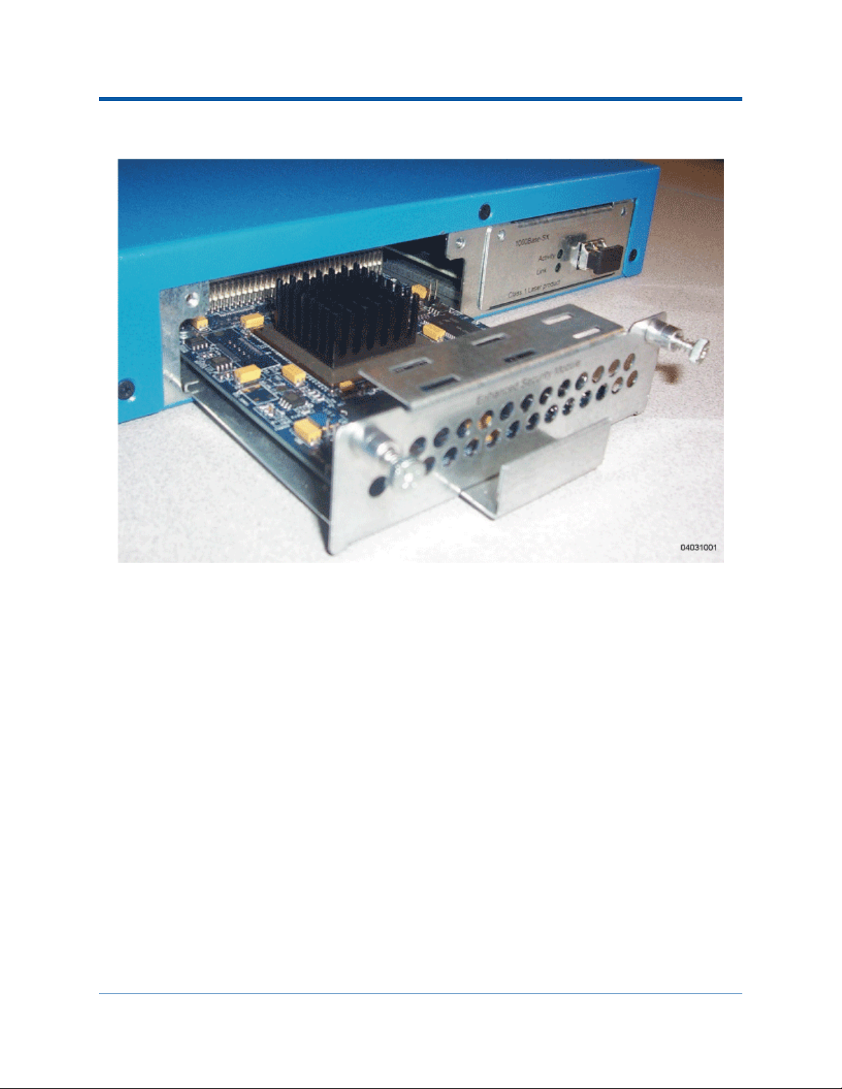
Figure - Alcatel OmniAccess Switch and Appliance Enhanced Security Module Location
3/17/04 Enhanced Security Module
90-100780-300 Rev 1 Alcatel OmniAccess Wireless Product Guide 34
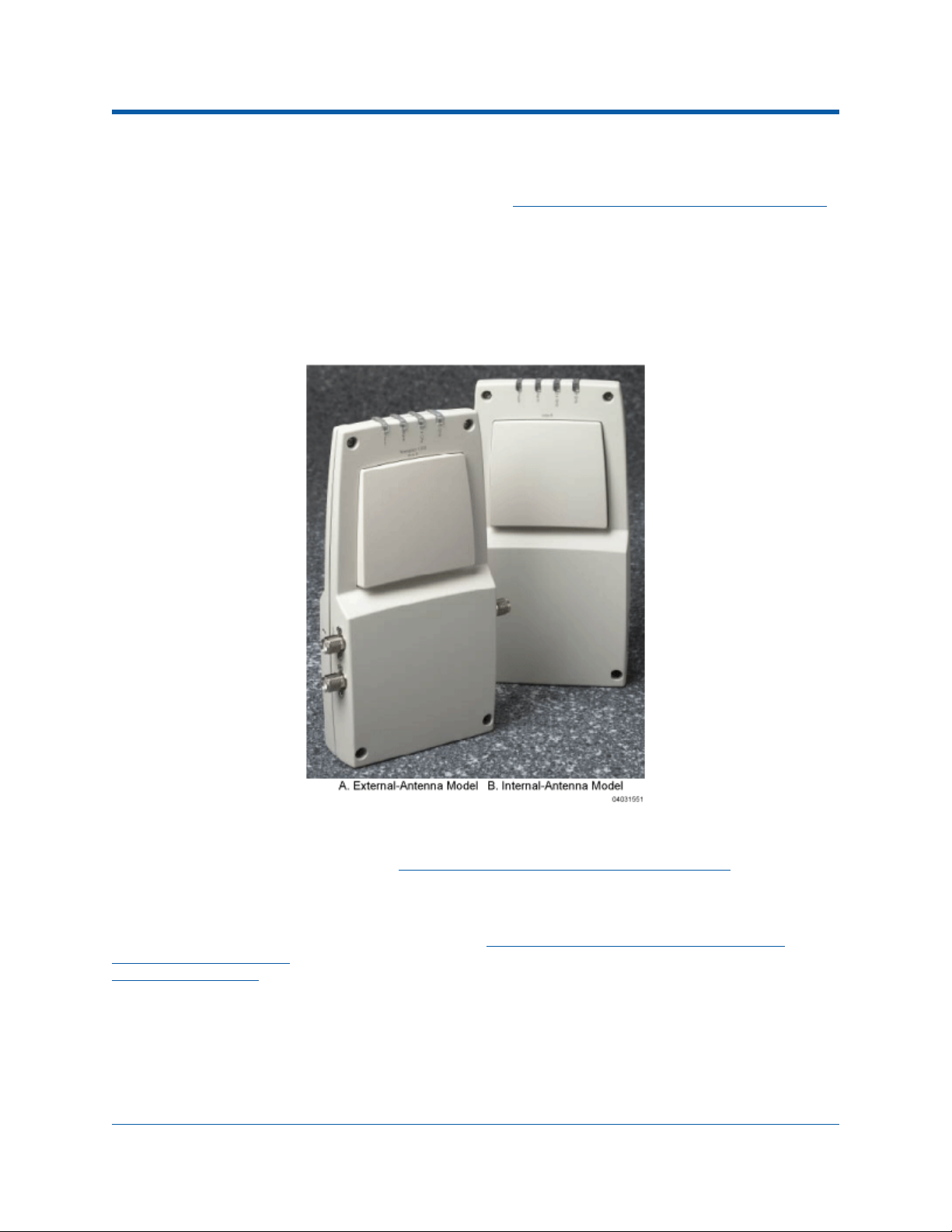
About Alcatel OmniAccess Wireless Access PointsAlcatel OmniAccess Wireless Access Points
The OmniAccess AP is a part of the innovative Alcatel OmniAccess Wireless Enterprise Platform (Alcatel
OmniAccess Wireless System). When associated with an Alcatel OmniAccess Switches and Appliances
as described below, the OmniAccess AP provides advanced 802.11a and/or 802.11b/g Access Point
functions in a single aesthetically pleasing plenum-rated enclosure. The following figure shows the two
types of Alcatel OmniAccess Wireless Access Point: without and with connectors for external antennas.
Note that Alcatel also offers an 802.11a/b/g Alcatel OmniAccess Remote Edge Access Points (OmniAccess 1200R APs), which are OmniAccess APs designed for remote deployment, OmniVista AirView
Software control via a WAN link, and which includes connectors for external antennas.
Figure - Alcatel OmniAccess Wireless Access Points
Note that the OmniAccess AP is manufactured in a neutral color so it blends into most environments
(but can be painted), contains pairs of high-gain internal antennas for unidirectional (180-degree) or
omnidirectional (360-degree) coverage (OmniAccess AP External and Internal Antennas
plenum-rated for installations in hanging ceiling spaces.
In the Alcatel OmniAccess Wireless System, most of the processing responsibility is removed from
traditional SOHO (small office, home office) APs and resides in the Alcatel OmniAccess Wireless
Switches and Appliances. The following figure shows Alcatel OmniAccess Wireless Access Points and
Third-Party Access Points
Direct-Connect Mode
3/17/04 Alcatel OmniAccess Wireless Access Points
90-100780-300 Rev 1 Alcatel OmniAccess Wireless Product Guide 35
connected to the 4012 or 4024 OmniAccess Wireless Switch front panel in
.
), and is

Figure - 4012 and 4024 OmniAccess Wireless Switch and Access Points
Refer to the following for more information on OmniAccess APs:
• Alcatel OmniAccess Remote Edge Access Points (OmniAccess 1200R APs)
• OmniAccess AP Models
• OmniAccess AP External and Internal Antennas
• OmniAccess AP LEDs
• OmniAccess AP Connectors
• OmniAccess AP Power Requirements
• OmniAccess AP External Power Supply
• OmniAccess AP Mounting Options
• OmniAccess AP Physical Security
• Monitor Mode
• Alcatel OmniAccess Wireless Access Point Deployment Guide
About Alcatel OmniAccess Remote Edge Access PointsAlcatel OmniAccess Remote Edge Access Points (OmniAccess 1200R APs)
The only exception to the general rule of Alcatel OmniAccess Wireless Access Points being continuously
controlled by Alcatel OmniAccess Switches or Appliances is the Alcatel OmniAccess Remote Edge Access
Point (OmniAccess AP 1200R). The OmniAccess AP 1200R is intended to be located at a remote site,
initially configured by an Alcatel OmniAccess Switch or Appliance, and normally controlled by an Alcatel
OmniAccess Switch or Appliance.
However, because the OmniAccess AP 1200R bridges the client data (compared with other OmniAccess
APs, which pass all client data through their respective Alcatel OmniAccess Switch or Appliance), if the
WAN link breaks between the OmniAccess AP 1200R and its Alcatel OmniAccess Switch or Appliance,
the OmniAccess AP 1200R continues transmitting WLAN 1 client data through other OmniAccess 1200R
APs on its local subnet. However, it cannot take advantage of features accessed from the Alcatel OmniAccess Switch or Appliance, such as establishing new VLANs, until communication is reestablished.
The OmniAccess AP 1200R includes the traditional SOHO (small office, home office) AP processing
power, and thus can continue operating if the WAN link to its associated Alcatel OmniAccess Switch or
Appliance fails. Because it is configured by its associated Alcatel OmniAccess Switch or Appliance, it has
the same WLAN configuration as the rest of the Alcatel OmniAccess Wireless System (refer to Alcatel
WLANs). As long as it remains connected to its Alcatel OmniAccess Switch or Appliance, it varies its
3/17/04 Alcatel OmniAccess Remote Edge Access Points (OmniAccess 1200R APs)
90-100780-300 Rev 1 Alcatel OmniAccess Wireless Product Guide 36

transmit power and channel selection under control of the OmniVista AirView Software, and performs
the same Rogue AP location as any other OmniAccess AP.
Note that the OmniAccess AP 1200R can support multiple WLANs while it is connected to its Alcatel
OmniAccess Switch or Appliance. However, when it loses connection to its Alcatel OmniAccess Switch or
Appliance, it supports only one WLAN on its local subnet.
The following figure shows a typical OmniAccess AP 1200R configuration:
Note that the OmniAccess AP 1200R must have a DHCP server available on its local subnet, so it can
obtain an IP address upon reboot. Also note that the OmniAccess 1200R APs at each remote location
must be on the same subnet to allow client roaming.
Refer to the following for more information on OmniAccess APs:
• Alcatel OmniAccess Wireless Access Points
• OmniAccess AP Models
• OmniAccess AP External and Internal Antennas
• OmniAccess AP LEDs
• OmniAccess AP Connectors
• OmniAccess AP Power Requirements
• OmniAccess AP External Power Supply
• OmniAccess AP Mounting Options
• OmniAccess AP Physical Security
• Monitor Mode
• Alcatel OmniAccess Wireless Access Point Deployment Guide
3/17/04 Alcatel OmniAccess Remote Edge Access Points (OmniAccess 1200R APs)
90-100780-300 Rev 1 Alcatel OmniAccess Wireless Product Guide 37

• Internal-Antenna Alcatel OmniAccess Wireless Access Point Quick Installation Guide
About OmniAccess AP ModelsOmniAccess AP Models
The OmniAccess AP includes one 802.11b/802.11g radio (OAW-1200BGE), or one 802.11a and one
802.11b/g radio (OAW-1200ABGE and OAW-1200ABGR). The OmniAccess AP is available in the
following configurations:
• OAW-1200BGE - OmniAccess AP with one 802.11b/g radio and four high-gain internal
antennas, one 5 GHz external antenna adapter, and two 2.4 GHz external antenna adapters.
• OAW-1200BG - OmniAccess AP with one 802.11b/g radio, four high-gain internal antennas, and
no external antenna adapters.
• OAW-1200ABGE - OmniAccess AP with one 802.11a and one 802.11b/g radio and four
high-gain internal antennas, one 5 GHz external antenna adapter, and two 2.4 GHz external
antenna adapters.
• OAW-1200ABG - OmniAccess AP with one 802.11a and one 802.11b/g radio, four high-gain
internal antennas, and no external antenna adapters.
• OAW-1200ABGR - Alcatel OmniAccess Remote Edge Access Point (OmniAccess AP 1200R) with
one 802.11a and one 802.11b/g radio and four high-gain internal antennas, one 5 GHz external
antenna adapter, and two 2.4 GHz external antenna adapters.
The OmniAccess AP is shipped with a color-coordinated ceiling mount base and hanging-ceiling rail
clips. You can also order projection- and flush-mount sheet metal wall mounting bracket kits. The base,
clips, and optional brackets allow quick mounting to ceiling or wall.
The OmniAccess AP can be powered by Power Over Ethernet or by an OmniAccess AP External Power
Supply. The external power supply model is:
• OAW-AP-PWR - Optional External 110-220 VAC-to-48 VDC Power Supply for any OmniAccess
AP.
The Single Inline PoE injector model is:
• OAW-IPWR - Optional Single 802.3af Inline Power over Ethernet Injector for any OmniAccess
AP, powered by 90-250 VAC.
The projection and flush sheet metal wall mount bracket model is:
• OAW-WAL-BKT - Optional sheet metal wall-mount bracket kit for any OmniAccess AP. Includes
one projection-mount and one flush-mount bracket per kit.
About OmniAccess AP External and Internal AntennasOmniAccess AP External and Internal Antennas
Note: OmniAccess APs and OmniAccess 1200R APs must use the factory-supplied internal or
external antennas to avoid violating FCC requirements and voiding the user’s authority to
operate the equipment. Refer to FCC Statements for OmniAccess APs
The 1200 OmniAccess AP and OmniAccess AP 1200R enclosure contains one 802.11a and/or one
802.11b/g radio and four (two 802.11a and two 802.11b/g) high-gain antennas, which can be independently enabled or disabled to produce a 360-degree omnidirectional coverage area.
Note that the wireless LAN operator can disable either one of each pair of the OmniAccess AP internal
antennas to produce a 180-degree sectorized coverage area. This feature can be useful, for instance,
for outside-wall mounting locations where coverage is only desired inside the building, and in a
back-to-back arrangement that can allow twice as many clients in a given area.
The following sections contain more information about OmniAccess AP internal and external antennas:
• External Antenna Connectors
3/17/04 OmniAccess AP Models
90-100780-300 Rev 1 Alcatel OmniAccess Wireless Product Guide 38
for detailed information.

• Antenna Sectorization
• 802.11a Internal Antenna Patterns
• 802.11b/g Internal Antenna Patterns
External Antenna ConnectorsExternal Antenna Connectors
The OAW-1200BGE, OAW-1200ABGE and OAW-1200ABGR OmniAccess APs and Alcatel OmniAccess
Remote Edge Access Points have male reverse-polarity TNC jacks for installations requiring
factory-supplied external directional or high-gain antennas. The external antenna option can create
more flexibility in OmniAccess AP and OmniAccess AP 1200R antenna placement.
Note: The OAW-1200BG, and OAW-1200ABG OmniAccess APs are designed to be used exclu-
sively with the internal high-gain antennas, and have no jacks for external antennas.
Note that the 802.11b/g 2.4 GHz Left external antenna connector is associated with the internal Side A
antenna, and that the 2.4 GHz Right external antenna connector is associated with the internal Side B
antenna. When you have 802.11b/g diversity enabled, the Left external or Side A internal antennas are
diverse from the Right external or Side B internal antennas.
Also note that the 802.11a 5 GHz Left external antenna connector is separate from the internal
antennas, and adds diversity to the 802.11a transmit and receive path. Note that no external 802.11a
antennas are certified in FCC-regulated areas, but external 802.11a antennas may be certified for use
in other regulatory domains.
Antenna SectorizationAntenna Sectorization
Note that the Alcatel OmniAccess Wireless System supports Antenna Sectorization, which can be used
to increase the number of clients and/or client throughput in a given air space. Installers can mount
two OmniAccess APs and/or OmniAccess 1200R APs back-to-back, and the Alcatel OmniAccess Wireless
System operator can disable the second antenna in both OmniAccess APs or OmniAccess 1200R APs to
create a 360-degree coverage area with two sectors.
Installers can also mount OmniAccess APs and/or OmniAccess 1200R APs on the periphery of a building
and disable the Side B internal antennas. This configuration can be used to supply service to the
building interior without extending coverage to the parking lot, at the cost of eliminating the internal
antenna diversity function.
802.11a Internal Antenna Patterns802.11a Internal Antenna Patterns
The OAW-1200ABG, OAW-1200ABGE and OAW-1200ABGR OmniAccess APs and Alcatel OmniAccess
Remote Edge Access Points contain one 802.11a radio, which drives two fully-enclosed high-gain
antennas that provide a large 360-degree coverage area. The two internal antennas are used at the
same time to provide a 360-degree (Omnidirectional) coverage area, or either antenna can be disabled
to provide a 180-degree (Sectorized) coverage area.
When equipped with an optional factory-supplied external antenna, the OAW-1200ABG,
OAW-1200ABGE and OAW-1200ABGR 802.11a OmniAccess Radio supports receive and transmit
diversity between the internal antennas and the external antenna. The diversity function provided by
OmniAccess Radios can result in lower multipath fading, fewer packet retransmissions, and higher
client throughput.
3/17/04 OmniAccess AP External and Internal Antennas
90-100780-300 Rev 1 Alcatel OmniAccess Wireless Product Guide 39

Figure - 1200 OmniAccess AP 802.11a OMNI (Dual Internal) Azimuth Antenna Gain Pattern
Figure - 1200 OmniAccess AP 802.11a OMNI (Dual Internal) Elevation Antenna Gain Pattern
3/17/04 OmniAccess AP External and Internal Antennas
90-100780-300 Rev 1 Alcatel OmniAccess Wireless Product Guide 40

Figure - 1200 OmniAccess AP 802.11a Sectorized (Single Internal) Azimuth Antenna Gain Pattern
Figure - 1200 OmniAccess AP 802.11a Sectorized (Single Internal) Elevation Antenna Gain Pattern
802.11b/g Internal Antenna Patterns802.11b/g Internal Antenna Patterns
The OAW-1200BG, OAW-1200BGE, OAW-1200ABG, OAW-1200ABGE and OAW-1200ABGR OmniAccess
APs and Alcatel OmniAccess Remote Edge Access Points contain one 802.11b/g radio which drives two
fully-enclosed high-gain antennas which can provide a large 360-degree coverage area. The two
internal antennas can be used at the same time to provide a 360-degree (Omnidirectional) coverage
area, or either antenna can be disabled to provide a 180-degree (Sectorized) coverage area.
The OAW-1200BG, OAW-1200BGE, OAW-1200ABG, OAW-1200ABGE and OAW-1200ABGR 802.11b/g
OmniAccess Radios support receive and transmit diversity between the internal antennas and/or
optional factory-supplied external antennas.
3/17/04 OmniAccess AP External and Internal Antennas
90-100780-300 Rev 1 Alcatel OmniAccess Wireless Product Guide 41

Figure - 1200 OmniAccess AP 802.11b/g OMNI (Dual Internal) Azimuth Antenna Gain Pattern
Figure - 1200 OmniAccess AP 802.11b/g OMNI (Dual Internal) Elevation Antenna Gain Pattern
3/17/04 OmniAccess AP External and Internal Antennas
90-100780-300 Rev 1 Alcatel OmniAccess Wireless Product Guide 42

Figure - 1200 OmniAccess AP 802.11b/g Sectorized (Single Internal) Azimuth Antenna Gain Pattern
Figure - 1200 OmniAccess AP 802.11b/g Sectorized (Single Internal) Elevation Antenna Gain Pattern
About OmniAccess AP LEDsOmniAccess AP LEDs
Each OmniAccess AP is equipped with four LEDs across the top of the case. They can be viewed from
nearly any angle. The LEDs indicate power and fault status, 2.4 GHz (802.1 1 b /g) OmniA c ce ss Rad io
activity, and 5 GHz (802.11a) OmniAccess Radio activity.
This LED display allows the wireless LAN manager to quickly monitor the OmniAccess AP status. For
more detailed troubleshooting instructions, refer to the Troubleshooting
3/17/04 OmniAccess AP LEDs
90-100780-300 Rev 1 Alcatel OmniAccess Wireless Product Guide 43
section.
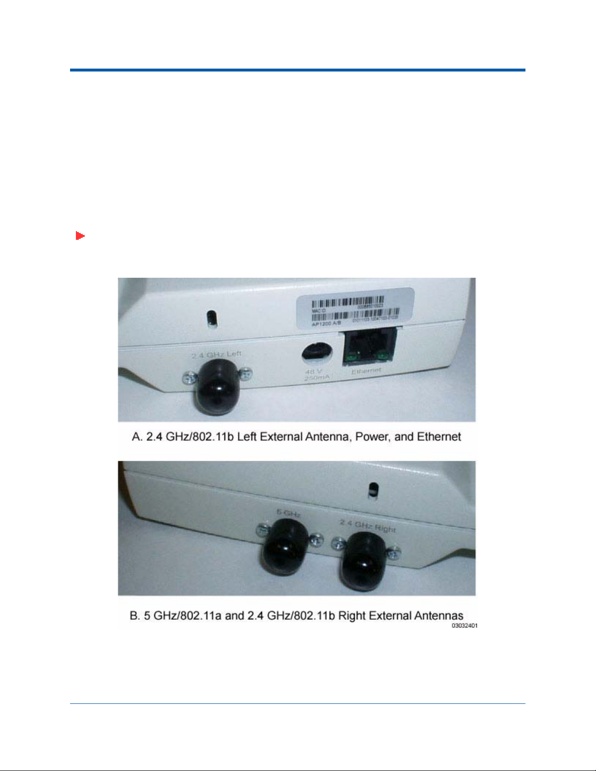
About OmniAccess AP ConnectorsOmniAccess AP Connectors
The OAW-1200BGE, OAW-1200ABGE and OAW-1200ABGR OmniAccess APs and Alcatel OmniAccess
Remote Edge Access Points have the following external connectors:
• One RJ-45 Ethernet jack, used for connecting the OmniAccess AP or OmniAccess AP 1200R to
the 4012 or 4024 OmniAccess Wireless Switch or to the network.
• One 48 VDC power input jack, used to plug in an optional factory-supplied external power
adapter.
• Three male reverse-polarity TNC antenna jacks, used to plug optional external antennas into
the OmniAccess AP or OmniAccess AP 1200R: two for an 802.11b/g radio, and one for an
802.11a radio.
Note: The OAW-1200BG and OAW-1200ABG OmniAccess APs are designed to be used exclu-
sively with the internal high-gain antennas, and have no jacks for external antennas.
Figure - OmniAccess AP and OmniAccess AP 1200R External Antenna Connectors
The OmniAccess AP or OmniAccess AP 1200R communicates with an Alcatel OmniAccess Wireless
Switch or Appliance using standard CAT-5 (Category 5) or higher 10/100 Mbps twisted pair cable with
3/17/04 OmniAccess AP Connectors
90-100780-300 Rev 1 Alcatel OmniAccess Wireless Product Guide 44

RJ-45 connectors. Plug the CAT-5 cable into the RJ-45 jack on the side of the OmniAccess AP or OmniAccess AP 1200R.
Note that the OmniAccess AP or OmniAccess AP 1200R can receive power over the CAT-5 cable from
the OmniAccess Wireless Switch or network equipment. Refer to Power Over Ethernet for more information about this option.
The OmniAccess AP or OmniAccess AP 1200R can be powered from an optional factory-supplied
external AC-to-48 VDC power adapter. If you are powering the OmniAccess AP or OmniAccess AP
1200R using an external adapter, plug the adapter into the 48 VDC power jack on the side of the OmniAccess AP or OmniAccess AP 1200R.
The OmniAccess AP or OmniAccess AP 1200R includes two 802.11a and two 802.11b/g high-gain
internal antennas, which provide omnidirectional coverage. However, some OmniAccess AP models and
the OmniAccess AP 1200R can also use optional factory-supplied external high-gain and/or directional
antennas, as described in OmniAccess AP External and Internal Antennas
antennas, plug them into the male reverse-polarity TNC jacks on the side of the OAW-1200BGE,
OAW-1200ABGE OmniAccess APs and OAW-1200ABGR OmniAccess AP 1200R as described in the
Internal-Antenna Alcatel OmniAccess Wireless Access Point Quick Installation Guide
. When you are using external
.
Note: The OmniAccess APs and OmniAccess 1200R APs must use the factory-supplied internal
or external antennas to avoid violating FCC regulations and voiding the user’s authority to
operate the equipment, as described in FCC Statements for OmniAccess APs.
About OmniAccess AP Power RequirementsOmniAccess AP Power Requirements
Each OmniAccess AP or and Alcatel OmniAccess Remote Edge Access Point (OmniAccess AP 1200R)
requires a 48 VDC nominal (between 38 and 57 VDC) power source capable of providing 7 Watts. The
polarity of the DC source does not matter because the OmniAccess AP can use either a +48 VDC or a
-48 VDC nominal source.
OmniAccess APs can receive power from an OmniAccess AP External Power Supply (which draws power
from a 110-220 VAC convenience outlet) plugged into the side of the OmniAccess AP case, or from
Power Over Ethernet
.
3/17/04 OmniAccess AP Power Requirements
90-100780-300 Rev 1 Alcatel OmniAccess Wireless Product Guide 45

Figure - Typical OmniAccess AP External Power Supply
For more information about the OmniAccess AP specifications and capacities, refer to Specifications
available in the Alcatel Marketing Literature.
,
About OmniAccess AP External Power SupplyOmniAccess AP External Power Supply
The OmniAccess AP or OmniAccess AP 1200R can receive power from an external
110-220 VAC-to-48 VDC power supply or from Power Over Ethernet equipment.
The external power supply (OAW-AP-PWR) plugs into a secure 110 through 220 VAC convenience
outlet. The converter produces the required 48 VDC output (OmniAccess AP Power Requirements) for
the OmniAccess AP. The converter output feeds into the side of the OmniAccess AP through a 48 VDC
jack (OmniAccess AP Connectors
).
About OmniAccess AP Mounting OptionsOmniAccess AP Mounting Optio n s
Refer to the Internal-Antenna Alcatel OmniAccess Wireless Access Point Quick Installation Guide for the
OmniAccess AP mounting options.
About OmniAccess AP Physical SecurityOmniAccess AP Physical Security
The side of the OmniAccess AP housing includes a slot for a Kensington MicroSaver Security Cable. You
can use any MicroSaver Security Cable to ensure that your OmniAccess AP stays where you mounted it!
Refer to the Kensington website for more information about their security products, or to the
Internal-Antenna Alcatel OmniAccess Wireless Access Point Quick Installation Guide
instructions.
for installation
3/17/04 OmniAccess AP External Power Supply
90-100780-300 Rev 1 Alcatel OmniAccess Wireless Product Guide 46

About OmniAccess AP Monitor ModeMonitor Mode
The OmniAccess APs, Alcatel OmniAccess Remote Edge Access Points (OmniAccess 1200R APs), Alcatel
OmniAccess Wireless Switches, and OmniAccess Wireless Appliances are capable of performing rogue
detection and containment while providing regular service.
However, if the administrator would prefer to dedicate specific OmniAccess APs to rogue detection and
containment, or if a network that provides only Wireless Protection Service (WPS) functions is desired,
the Monitor mode should be enabled for individual OmniAccess APs and OmniAccess 1200R APs.
The Monitor function is set for all 802.11 OmniAccess Radios on a per-OmniAccess AP basis in the
OmniAccess APs > Details
section in the Alcatel OmniAccess Wireless System Web Browser Online Help.
3/17/04 Monitor Mode
90-100780-300 Rev 1 Alcatel OmniAccess Wireless Product Guide 47

About Third-Party Access PointsThird-Party Access Points
The Alcatel OmniAccess Wireless System can control power and/or channel parameters for existing
Cisco 1200, Cisco 350 and ORiNOCO 2000 Access Points using the third-party AP user interface from
within the OmniVista Air Control System Software
Wireless System can be used to enforce real-time control of system-wide 802.1X security policies for
third-party AP WLANs as described in Alcatel Wireless Operating System Security
• ACS supports VxWorks versions of Cisco Aironet 1200 and Aironet 350 APs. Apart from status
monitoring, it allows configuring the channel and power level. The user is also allowed to
navigate from ACS GUI to AP web pages to make more involved configuration changes. The
MIB supported is the “ieee802dot11 MIB”.
• ACS also supports ORiNOCO 2000 APs for status monitoring and for configuring parameters
such as the Channel Select Mode, Channel Number, and Distance Between APs. The supported
MIB is “orinocco MIB”. ACS allows navigating to the AP web pages for more involved configuration changes.
Note: Third-party APs must be connected directly to the front panel of 4012 and 4024 Alcatel
OmniAccess Wireless Switches for the Alcatel Wireless Operating System to control them
using the third-party AP WLAN 17. Because the 4102 OmniAccess Wireless Appliances do not
have front-panel AP ports, WLAN 17 is not supported on the 4102 OmniAccess Wireless
Appliances.
application. In addition, the Alcatel OmniAccess
.
3/17/04 Third-Party Access Points
90-100780-300 Rev 1 Alcatel OmniAccess Wireless Product Guide 48

About Rogue Access PointsRogue Access Points
Because they are inexpensive and readily available, employees are plugging unauthorized rogue access
points (rogue APs) into existing LANs and building ad hoc wireless networks without IT department
knowledge or consent.
These rogues can be a serious breach of network security, because they can be plugged into a network
port behind the corporate firewall. Because employees generally do not enable any security settings on
the rogues, it is easy for unauthorized users to use the access point to intercept network traffic and
hijack client sessions. Even more alarming, wireless users and war chalkers frequently publish unsecure
access point locations, increasing the odds of having the enterprise security breached.
Rather than using a person with a scanner to manually detect rogue APs, the Alcatel OmniAccess
Wireless System automatically collects information on rogue access points detected by its managed
Alcatel OmniAccess Wireless Access Points
allows the system operator to locate, tag and monitor them as described in the Detecting and Locating
Rogue Access Points section. The Alcatel Wireless Operating System can also be used to discourage
rogue AP clients by sending them deauthenticate and disassociate messages from one to four OmniAccess APs. Finally, the Alcatel Wireless Operating System can be used to automatically discourage all
clients attempting to authenticate with all rogue APs on the enterprise subnet. Because this real-time
detection is automated, it saves labor costs used for detecting and monitoring rogue APs while vastly
improving LAN security.
Note that the peer-to-peer, or ad-hoc, clients can also be considered rogue APs. See also Rogue AP Location, Tagging and Containment
Rogue AP Location, Tagging and ContainmentRogue AP Location, Tagging and Containment
This built-in detection, tagging, monitoring and containment capability allows system administrators to
take required actions:
• Locate rogue APs as described in Detecting and Locating Rogue Access Points.
and Third-Party Access Points, by MAC and IP Address, and
.
• Receive new rogue notifications, eliminating hallway scans.
• Monitor unknown rogues until they are eliminated or acknowledged.
• Determine the closest authorized Alcatel OmniAccess Wireless Access Points and Third-Party
Access Points, making directed scans faster and more effective.
• Contain rogue APs by sending their clients deauthenticate and disassociate messages from one
to four OmniAccess APs. This containment can be done for individual rogue APs by MAC
address, or can be mandated for all rogue APs connected to the enterprise subnet.
• Tag rogue APs:
- Acknowledge rogue APs when they are outside of the LAN and do not compromise the
LAN or WLAN security.
- Accept rogue APs when they do not compromise the LAN or WLAN security.
- Tag rogue APs as unknown until they are eliminated or acknowledged.
- Tag rogue APs as contained and discourage clients from associating with the rogue AP,
by having between one and four OmniAccess APs transmit deauthenticate and
disassociate messages to all rogue AP clients. This function contains all active channels
on the same rogue AP.
To facilitate automated rogue detection in a crowded RF space, OmniAccess APs can be configured to
operate in Monitor Mode
, allowing monitoring without creating unnecessary interference.
3/17/04 Rogue Access Points
90-100780-300 Rev 1 Alcatel OmniAccess Wireless Product Guide 49

About the OmniVista Air Control System SoftwareOmniVista Air Control System Softw a re
The OmniVista Air Control System Software (ACS Software Server) is an Alcatel Wireless Operating
System management tool that extends the capabilities of the Alcatel Web Browser Interface
Command Line Interface from an individual Alcatel OmniAccess Wireless Switch or Appliance to a
network of Alcatel OmniAccess Switches and Appliances.
The ACS Software Server includes the same configuration, performance monitoring, security, fault
management, and accounting options used at the Alcatel OmniAccess Switch and Appliance level, but
adds a graphical view of multiple Alcatel OmniAccess Wireless Switches, OmniAccess Wireless Appliances and managed Access Points.
ACS Software Server simplifies configuring and monitoring Alcatel OmniAccess Switches and Appliances
while decreasing data entry errors with the ACS Alcatel OmniAccess Switch and Appliance Auto-
discovery algorithm. The ACS Software Server also uses industry-standard SNMP protocol to
communicate with the Alcatel OmniAccess Switches and Appliances.
The ACS Software Server can be run as a normal Windows application, or can be installed as a service,
which runs continuously and resumes running after a reboot.
Note that the operator can access the ACS Software Server through the ACS Software Java Admin
Client, which allows the ACS Software Server administrator to administer user accounts and schedule
periodic maintenance tasks, and the ACS Software Browser Client, which allows ACS Software Server
operators to control all other permitted ACS Software functions.
The ACS Software also includes the ACS Floor Plan Editor, which allows you to vectorize bitmapped
campus, floor plan, and outdoor area maps, add and change wall types, and import the resulting .FPE
wall format maps into the ACS Software database. The .FPE files allow the ACS RF Prediction Tool to
make much better RF predictions based on OmniAccess AP signal strength, and accurate wall and
window RF attenuation.
The value added by ACS Software includes graphical views of the following:
• Auto-discovery of Alcatel OmniAccess Wireless Access Points as they associate with Alcatel
OmniAccess Switches and Appliances, and manual association of Third-Party Access Points with
Alcatel OmniAccess Switches and Appliances.
• Auto-discovery of Rogue Access Points.
• Map-based organization of Access Point areas, helpful when the enterprise spans more than
one geographical area. (Refer to Configuring the ACS Software Browser Client.)
• User-supplied Campus, Building and Floor graphics, which show the following:
- Locations and status of managed Access Points. (Refer to Adding Devices to the ACS
Software Database.)
- Approximate locations of rogue APs, based on signal strength received by nearest
managed OmniAccess APs. (Refer to Detecting and Locating Rogue Access Points.)
- Coverage hole alarm information for APs is based on received signal strength from
clients. This information appears in a tabular rather than map format. (Refer to Finding
Coverage Holes.)
- RF coverage maps.
- Locations of rogue APs and clients.
• System-wide control:
- Network, OmniAccess Wireless Switch, OmniAccess Wireless Appliance and managed
AP configuration is streamlined using customer-defined templates.
- Network, OmniAccess Wireless Switch, OmniAccess Wireless Appliance and managed
AP status and alarm monitoring.
and the
3/17/04 OmniVista Air Control System Software
90-100780-300 Rev 1 Alcatel OmniAccess Wireless Product Guide 50

- Automated monitoring: rogue APs, coverage holes, security violations, Alcatel
OmniAccess Switches and Appliances, and OmniAccess APs.
- Full event logs available for rogue APs, coverage holes, security violations, Alcatel
OmniAccess Switches and Appliances, and OmniAccess APs.
- ACS Software Server allows navigating to a third-party AP native Web interface for
configuration and monitoring. Refer to Third-Party Access Points for supported
third-party AP models.
- Automatic channel and power level assignment by OmniVista AirView Software.
- User-defined automatic Alcatel OmniAccess Switches and Appliances status audits,
missed trap polling, configuration backups, and policy cleanups.
About the ACS Software Java Admin ClientACS Software Java Admin Client
The ACS Software Java Admin Client interface allows the ACS Software Server administrator to create,
modify and delete user accounts, change passwords, assign permissions, and schedule periodic maintenance tasks through a Java window. These administrative tasks are usually reserved to the ACS
Software Server administrator.
As part of user administration, the ACS Software Server administrator creates new usernames
passwords and assigns them to predefined permissions groups. This task is described in Managing ACS
Software and Database.
About the ACS Software Browser ClientACS Software Browser Client
The ACS Software Browser Client interface allows the ACS Software Server operator to create and
configure Alcatel OmniAccess Wireless System coverage area layouts, configure system operating
parameters, monitor real-time Alcatel OmniAccess Wireless System operation, and perform troubleshooting tasks using a standard HTTP or HTTPS Web Browser window.
Alcatel Internetworking, Inc. recommends the Internet Explorer 6.0 or later Web Browser for full access
to the ACS functionality, although Netscape Navigator and other Web Browsers are also supported with
a slightly altered look-and-feel.
Note: The HTTPS (SSL over HTTP) interface is enabled by default, and the HTTP interface can
be manually activated in the Command Line Interface, Alcatel Web Browser Interface and ACS
Software Browser Client.
The ACS Software Server administrator can create ACS Software Browser Client operator user names
and passwords, and can assign the individual operator accounts to various permission levels, from
read-only to full read-write control using the ACS Software Java Admin Client
ACS Software Browser Client operators perform their tasks as described in Using the OmniVista Air
Control System Software.
.
About the ACS Floor Plan EditorACS Floor Plan Editor
The ACS Floor Plan Editor converts architectural, mechanical and technical drawings, graphics, maps
and other types of line artwork from raster bitmaps to wall (vector) formats. Operators can use
scanners to digitize paper drawings into supported file formats for import into ACS. The ACS Floor Plan
Editor automatically recognizes and represents the data in a wall format which can then be imported
into your ACS (OmniVista Air Control System Software
Because of its ability to create smooth straight, angled, and semi-angled outlines, the ACS Floor Plan
Editor is used to convert floor plan maps, define the wall characteristics, and import the resulting .FPE
wall format maps into the ACS database. The .FPE files allow the ACS RF Prediction Tool to make much
3/17/04 ACS Software Java Admin Client
90-100780-300 Rev 1 Alcatel OmniAccess Wireless Product Guide 51
) program.

better RF predictions based on OmniAccess AP signal strength, and accurate wall, window and cubicle
RF attenuation.
Otherwise, you may want to save raster images in .BMP, .TIFF, .JPEG, or .PNG raster formats. Note
that you can also edit existing .FPE map files.
The output wall files can be saved in .FPE (Alcatel wall format) for importing directly into the ACS
database. The output wall files can also be saved in the following formats, but ACS does not recognize
these file types: .DXF (AutoCAD), .AI (Adobe Illustrator), .EMF (enhanced metafile), .WMF (Windows
metafile), and .TXT (ASCII XY).
Note that there are no restrictions on the input or output image size.
Note: The quality of ACS Floor Plan Editor recognition is higher for higher resolution data. Use
400 to 600 dots per inch (dpi) scans whenever possible.
Note: Alcatel strongly recommends that you create images with the long axis horizontal (land-
scape format) to ensure the best viewing in ACS.
About ACS Alcatel OmniAccess Switch and Appliance AutodiscoveryACS Alcatel OmniAccess Switch and Appliance Autodiscovery
Manually adding Alcatel OmniAccess Switch and Appliance data to a management database can be time
consuming, and is susceptible to data entry errors. The OmniVista Air Control System Software (ACS
Software Server) includes a built-in Alcatel OmniAccess Wireless Switch and Appliance configuration
upload function that speeds up database creation while eliminating errors.
Alcatel OmniAccess Switch and Appliance Autodiscovery is limited to the Alcatel Mobility Group subnets
defined by the Alcatel OmniAccess Wireless System operator.
ACS Alcatel OmniAccess Switch and Appliance Autodiscovery allows operators to search for a single
Alcatel OmniAccess Switch or Appliance by IP Address. The Autodiscovery function finds the Alcatel
OmniAccess Switch or Appliance on the network with the specified IP Address, and automatically enters
the discovered Alcatel OmniAccess Switch and Appliance information into the ACS Software Server
database.
As Alcatel OmniAccess Wireless Access Points
Access 1200R APs) associate with an Alcatel OmniAccess Switch or Appliance, the Alcatel OmniAccess
Switch or Appliance immediately transmits the OmniAccess AP or OmniAccess AP 1200R information to
the OmniVista Air Control System Software, which automatically adds the OmniAccess AP or OmniAccess AP 1200R to the ACS Software Server database.
Once the OmniAccess AP or OmniAccess AP 1200R information is in the ACS Software Server database,
operators can add the OmniAccess AP or OmniAccess AP 1200R to the appropriate spot on an ACS
Software Server map using Adding APs to Floor Plan and Open Area Maps
air space remains current.
or Alcatel OmniAccess Remote Edge Access Points (Omni-
, so the topological map of the
3/17/04 ACS Alcatel OmniAccess Switch and Appliance Autodiscovery
90-100780-300 Rev 1 Alcatel OmniAccess Wireless Product Guide 52

About the Alcatel Web Browser InterfaceAlcatel Web Browser Interface
The Alcatel Web Browser Interface is built into each Alcatel OmniAccess Switch and Appliance. The Web
Browser Interface allows up to five users to simultaneously browse into the built-in Alcatel OmniAccess
Wireless Switch or Appliance http/https (http + SSL) Web server, configure parameters, and monitor
operational status for the Alcatel OmniAccess Switch or Appliance and its associated Access Points.
Note: Alcatel strongly recommends that you enable the https: and disable the http: interfaces
to ensure more robust security for your Alcatel OmniAccess Wireless System.
Because the Alcatel Web Browser Interface works with one Alcatel OmniAccess Switch or Appliance at a
time, the Alcatel Web Browser Interface is especially useful when you wish to configure or monitor a
single Alcatel OmniAccess Switch or Appliance.
Note: Some popup window filters can be configured to block the Alcatel Web Browser Online
Help windows. If your system cannot display the Online Help windows, disable or reconfigure
your browser popup filter software.
Refer to Using the Alcatel Web Browser Interface for more information on the Alcatel Web Browser
Interface.
3/17/04 Alcatel Web Browser Interface
90-100780-300 Rev 1 Alcatel OmniAccess Wireless Product Guide 53

About the Command Line InterfaceCommand Line Interface
The Alcatel OmniAccess Wireless System Command Line Interface (CLI) is built into the Alcatel OmniAccess Wireless Switches and Appliances, and is one of the Alcatel Wireless Operating System user
interfaces described in About the Alcatel OmniAccess Wireless System
a VT-100 emulator to locally or remotely configure, monitor and control individual Alcatel OmniAccess
Switches and Appliances, and to access extensive debugging capabilities.
Because the CLI works with one Alcatel OmniAccess Switch or Appliance at a time, the Command Line
Interface is especially useful when you wish to configure or monitor a single Alcatel OmniAccess Switch
or Appliance.
The Alcatel OmniAccess Switch or Appliance and its associated OmniAccess APs can be configured and
monitored using the Command Line Interface (CLI), which consists of a simple text-based, tree-structured interface that allows up to five users with Telnet-capable terminal emulators to simultaneously
configure and monitor all aspects of the Alcatel OmniAccess Switch or Appliance and associated OmniAccess APs.
Refer to Using the Alcatel OmniAccess Wireless System CLI
System CLI Reference for more information.
and the Alcatel OmniAccess Wireless
. The CLI allows operators to use
3/17/04 Command Line Interface
90-100780-300 Rev 1 Alcatel OmniAccess Wireless Product Guide 54

SOLUTIONSSOLUTIONS
• Alcatel Wireless Operating System Security
• Converting an Alcatel OmniAccess Wireless System from Layer 2 to Layer 3 Mode
• Converting an Alcatel OmniAccess Wireless System from Layer 3 to Layer 2 Mode
• Configuring a Firewall for an ACS Software Server
• Configuring the System for SpectraLink NetLink Telephones
• Management over Wireless
• Configuring a WLAN for a DHCP Server
• Customizing the Web Auth Login Screen
• Configuring Identity Networking for Alcatel Wireless Operating System 2.0
3/17/04 © 2004 All Rights Reserved.
90-100780-300 Rev 1

Alcatel Wireless Operating System SecurityAlcatel Wireless Operating System Security
Alcatel Wireless Operating System Security includes the following sections:
• Overview
• Layer 1 Solutions
• Layer 2 Solutions
• Layer 3 Solutions
• Single Point of Configuration Policy Manager Solutions
• Rogue Access Point Solutions
• Integrated Security Solutions
• Simple, Cost-Effective Solutions
OverviewOverview
The industry-leading Alcatel Wireless Operating System Security solution bundles potentially complicated Layer 1, Layer 2 and Layer 3 802.11 Access Point security components into a simple policy
manager that customizes system-wide security policies on a per-WLAN basis (Alcatel Wireless
Operating System Security). Unlike SOHO (small office, home office) 802.11 products, the Alcatel
Wireless Operating System Security solution included in the Alcatel OmniAccess Wireless Enterprise
Platform (Alcatel OmniAccess Wireless System) provides simpler, unified, and systematic security
management tools.
One of the biggest hurdles to WLAN deployment in the enterprise is the WEP (Wired Equivalent Privacy)
encryption, which has proven to be a weak standalone encryption method. A newer problem is the
availability of low-cost APs, which can be connected to the enterprise network and used to mount
‘man-in-the-middle’ and denial-of-service attacks. Also, the complexity of add-on security solutions has
prevented many IT managers from embracing the new 802.11 benefits. Finally, the 802.11 security
configuration and management cost has been daunting for resource-bound IT departments.
Layer 1 SolutionsLayer 1 Solutions
The Alcatel Wireless Operating System Security solution ensures that all clients gain access within an
operator-set number of attempts. Should a client fail to gain access within that limit, it is automatically
disabled (blocked from access) until the operator-set timer expires.
Layer 2 SolutionsLayer 2 Solutions
If a higher level of security and encryption is required, the network administrator can also implement
industry-standard security solutions, such as: 802.1X dynamic keys with EAP (extended authorization
protocol), or WPA (Wi-Fi protected access) dynamic keys. The Alcatel WPA implementation includes
AES (advanced encryption standard), TKIP + Michael (temporal key integrity protocol + message
integrity code checksum) dynamic keys, or WEP (Wired Equivalent Privacy) static keys. Disabling is also
used to automatically block Layer 2 access after an operator-set number of failed authentication
attempts.
Regardless of the wireless security solution selected, all Layer 2 wired communications between Alcatel
OmniAccess Switches and Appliances and OmniAccess APs are secured by passing data through IPSec
tunnels.
3/17/04 Alcatel Wireless Operating System Security
90-100780-300 Rev 1 Alcatel OmniAccess Wireless Product Guide 56

Layer 3 SolutionsLayer 3 Solutions
The WEP problem can be further solved using industry-standard Layer 3 security solutions, such as
VPNs (virtual private networks) and IPSec (IP security) protocols. The Alcatel IPSec implementation
includes IKE (internet key exchange), DH (Diffie-Hellman) groups, and three optional levels of encryption: DES (ANSI X.3.92 data encryption standard), 3DES (ANSI X9.52-1998 data encryption standard),
or AES/CBC (advanced encryption standard/cipher block chaining). Disabling is also used to automatically block Layer 3 access after an operator-set number of failed authentication attempts.
The Alcatel IPSec implementation also includes industry-standard authentication using: MD5 (message
digest algorithm), or SHA-1 (secure hash algorithm-1).
The Alcatel OmniAccess Wireless System supports local and RADIUS MAC (media access control)
filtering. This filtering is best suited to smaller client groups with a known list of 802.11 access card
MAC addresses.
Finally, the Alcatel OmniAccess Wireless System supports local and RADIUS user/password authentication. This authentication is best suited to small to medium client groups.
Single Point of Configuration Policy Manager SolutionsSingle Point of Configuration Policy Manager Solutions
When the Alcatel OmniAccess Wireless System is equipped with OmniVista Air Control System
Software, you can configure system-wide security policies on a per-WLAN basis. SOHO Access Points
force you to individually configure security policies on each AP, or use a third-party appliance to
configure security policies across multiple APs.
Because the Alcatel OmniAccess Wireless System security policies can be applied across the whole
system from the OmniVista Air Control System Software, errors can be eliminated and the overall effort
is greatly reduced.
Rogue Access Point SolutionsRogue Access Point Solutions
Rogue Access Point ChallengesRogue Access Point Challenges
Rogue Access Points can disrupt WLAN operations by hijacking legitimate clients and using plaintext or
other denial-of-service or man-in-the-middle attacks. That is, a hacker can use a rogue access point to
capture sensitive information, such as passwords and username. The hacker can then transmit a series
of clear-to-send (CTS) frames, which mimics an access point informing a particular NIC to transmit and
instructing all others to wait, which results in legitimate clients being unable to access the WLAN
resources. WLAN service providers thus have a strong interest in banning rogue access points from the
air space.
The Alcatel Wireless Operating System Security solution uses the OmniVista AirView Software
to continuously monitor all nearby OmniAccess APs, and automatically discover rogue access points,
and locate them as described in Detecting and Locating Rogue Access Points.
Tagging and Containing Rogue Access PointsTagging and Containing Rogue Access Points
When the Alcatel OmniAccess Wireless System is monitored using OmniVista Air Control System
Software, the ACS Software Server generates the flags as rogue access point traps, and displays the
known rogue access points by MAC address. The operator can then display a map showing the location
of the OmniAccess APs closest to each rogue access point, allowing Known or Acknowledged rogues (no
further action), marking them as Alert rogues (watch for and notify when active), or marking them as
Contained rogues (have between one and four OmniAccess APs Discourage rogue access point clients
by sending the clients deauthenticate and disassociate messages whenever they associate with the
rogue access point).
When the Alcatel OmniAccess Wireless System is monitored using an Alcatel Web Browser Interface
an Command Line Interface, the interface displays the known rogue access points by MAC address. The
function
or
3/17/04 Alcatel Wireless Operating System Security
90-100780-300 Rev 1 Alcatel OmniAccess Wireless Product Guide 57

operator then has the option of marking them as Known or Acknowledged rogues (no further action),
marking them as Alert rogues (watch for and notify when active), or marking them as Contained rogues
(have between one and four OmniAccess APs Discourage rogue access point clients by sending the
clients deauthenticate and disassociate messages whenever they associate with the rogue access
point).
Integrated Security SolutionsIntegrated Security Solutions
• Alcatel Wireless Operating System Security is built around a robust 802.1X AAA (authorization,
authentication and accounting) engine, which allows operators to rapidly configure and enforce
a variety of security policies across the Alcatel OmniAccess Wireless System.
• The Alcatel OmniAccess Switches and Appliances and Alcatel OmniAccess Wireless Access
Points are equipped with system-wide authentication and authorization protocols across all
ports and interfaces, maximizing system security.
• Alcatel Wireless Operating System Security policies are assigned to individual WLANs, and
Alcatel OmniAccess Wireless Access Points
WLANs. This can eliminate the need for additional APs, which can increase interference and
degrade system throughput.
• The Alcatel OmniAccess Switches and Appliances securely terminates IPSec VPN clients, which
can reduce the load on centralized VPN concentrators.
• Alcatel Wireless Operating System Security uses the OmniVista AirView Software function to
continually monitor the air space for interference and security breaches, and notify the operator
when they are detected.
• Alcatel Wireless Operating System Security works with industry-standard aaa (authorization,
authentication and accounting) servers, making system integration simple and easy.
• The Alcatel Wireless Operating System Security solution offers comprehensive Layer 2 and
Layer 3 encryption algorithms which typically require a large amount of processing power.
Rather than assigning the encryption tasks to yet another server, the Alcatel OmniAccess
Switch and Appliance can be equipped with an Enhanced Security Module that provides extra
hardware required for the most demanding security configurations.
simultaneously broadcast all (up to 16) configured
Simple, Cost-Effective SolutionsSimple, Cost-Effective Solutions
Because the Alcatel OmniVista AirView Software function is enabled from the factory, the IT department does not need to create a detailed rollout plan to continually monitor APs, or to individually
update APs, resulting in very low input required from the IT department or Wireless LAN manager. This
means less money spent deploying, configuring, updating, and monitoring the Alcatel OmniAccess
Wireless System.
3/17/04 Alcatel Wireless Operating System Security
90-100780-300 Rev 1 Alcatel OmniAccess Wireless Product Guide 58

Converting an Alcatel OmniAccess Wireless System from Layer 2 to
Layer
When you wish to convert an Alcatel OmniAccess Wireless System from Layer 2 to Layer 3 Mode, use
one of the following procedures:
Using the Alcatel OmniAccess Switch or Appliance Web BrowserUsing the Alcatel OmniAccess Switch or Appliance Web Browser
When you wish to convert an Alcatel OmniAccess Wireless System from Layer 2 to Layer 3 LWAPP
Transport Mode using the Alcatel OmniAccess Switch or Appliance Web Browser Interface, complete the
following steps:
3 ModeConverting an Alcatel OmniAccess Wireless System from Layer 2 to Layer 3 Mode
• Using the Alcatel OmniAccess Switch or Appliance Web Browser
• Using the ACS Software Browser Client Interface
CAUTION: This procedure will cause your OmniAccess APs to go offline until the Alcatel Omni-
Access Switch or Appliance reboots and the associated OmniAccess APs reassociate with the
Alcatel OmniAccess Switch or Appliance.
Note: Layer 3 Mode requires that all subnets that the Alcatel OmniAccess Switches or Appli-
ances are connected to include at least one DHCP server. When you have completed this
procedure, the Alcatel OmniAccess Switch or Appliance stores its IP address in its associated
OmniAccess APs. When each OmniAccess AP is powered up, it obtains an IP address from the
local DHCP server, and connects to its Primary Alcatel OmniAccess Switch or Appliance IP
address.
Note: Layer 3 Mode requires that all subnets that contain Alcatel OmniAccess Wireless
Switches, OmniAccess Wireless Appliances and OmniAccess APs are routable to each other.
1. To use the Alcatel OmniAccess Wireless System in Layer 3 mode, you must create an
AP Manager Interface, which manages communications between each Alcatel OmniAccess
Switch or Appliance and its associated OmniAccess APs. This AP Manager Interface will require
a fixed IP address, which must be different from the Management Interface IP address, but
which can be on the same subnet as the Management Interface.
2. MAKE SURE that all the Alcatel OmniAccess Wireless Switches, OmniAccess Wireless Appli-
ances, and OmniAccess APs are on the same subnet: that they are only connected through
Layer 2 devices. If possible, connect the OmniAccess APs directly (or through Layer 2 devices)
to the front-panel 10/100Base-T ports on any 4012 or 4024 OmniAccess Wireless Switch.
CAUTION: This step is very important! You must configure the Alcatel OmniAccess Switches
or Appliances and associated OmniAccess APs to operate in Layer 3 mode BEFORE completing
the conversion.
3. Verify that the OmniAccess APs are assigned to the desired Alcatel OmniAccess Switch or Appli-
ance. If you do not complete this step, the OmniAccess APs will fail to associate with the Alcatel
OmniAccess Switch or Appliance after completing the conversion.
A. Select WIRELESS/OmniAccess APs to navigate to the OmniAccess APs page, and
click Detail to have the Web Browser interface display the OmniAccess APs >
Details page.
B. On the OmniAccess APs > Details page for each OmniAccess AP, verify that the Pri-
mary Switch Name is correct. If you change the Primary Switch Name, click Apply to
save the change to the OmniAccess AP.
4. Select WIRELESS/OmniAccess APs to navigate to the OmniAccess APs page, and MAKE
SURE that all the OmniAccess APs are listed before you continue with the next step.
If you do not complete this step, the OmniAccess APs may fail to associate with the Alcatel
OmniAccess Switch or Appliance after completing the conversion.
3/17/04 Converting an Alcatel OmniAccess Wireless System from Layer 2 to Layer 3
Mode
90-100780-300 Rev 1 Alcatel OmniAccess Wireless Product Guide 59

5. Change the LWAPP Transport Mode from Layer 2 to Layer 3:
A. Select SWITCH/General to navigate to the General page, and change Layer 2 LWAPP
Transport Mode to Layer 3.
B. Click Apply to send th e changes to the Alcatel Omn iAccess Switch or Appliance and the
associated OmniAccess APs. Click OK to continue.
6. Select COMMANDS/Reboot to navigate to the System Reboot page, and click Reboot to
display the Reboot System > Save? page.
7. In the Reboot System > Save? page, click Save and Reboot to have the Alcatel Wireless Oper-
ating System save the new configuration to and reboot the Alcatel OmniAccess Switch or
Appliance.
The Alcatel OmniAccess Switch or Appliance reboots.
8. Select SWITCH/Interfaces to navigate to the Interfaces page, and verify that Alcatel
Wireless Operating System has automatically added the ap-manager interface.
9. Configure the ap-manager interface. In the Interfaces page, click the ap-manager Interface
Edit button to have the Web Browser display the Interfaces > Edit page. In the Interfaces >
Edit page:
- Optionally add a VLAN Identifier.
- Enter the ap-manager IP Address and Netmask obtained in Step 1.
- Add a Gateway IP address.
- Enter the physical port number for the Distribution System connection to the Alcatel
OmniAccess Switch or Appliance.
- Enter a Primary DHCP Server IP address.
- Enter a Secondary DHCP Server IP address. (This can be the same as the Primary
DHCP Server IP address if you do not have a second DHCP server on this subnet.)
- Optionally select an ACL (Access Control List) from the pulldown menu.
- Click Apply to add the edited AP Manager Interface definition to the list of interfaces.
10. From the Interfaces page, verify that the management interface is properly configured with
a different IP Address than the ap-manager interface.
11. Save the new configuration and restart your Alcatel OmniAccess Wireless System:
A. Select COMMANDS/Reboot to navigate to the System Reboot page, and select
Reboot.
B. On the Reboot System > Save page, click Save and Reboot to save the changes to
and reboot the Alcatel OmniAccess Switch or Appliance.
C. Click OK to confirm the save and reboot.
12. After the Alcatel OmniAccess Switch or Appliance has rebooted, select SWITCH/General to
navigate to the General page, and verify that the LWAPP Transport Mode is set to Layer 3.
13. Power down each OmniAccess AP to save the Layer 3 configuration to nonvolatile memory.
14. Connect each OmniAccess AP to its final location in the network. Each OmniAccess AP connects
to its Primary Alcatel OmniAccess Switch or Appliance, downloads a copy of the latest Alcatel
Wireless Operating System code, and starts reporting its status to the Alcatel OmniAccess
Switch or Appliance. Note that this can take a few minutes for each OmniAccess AP.
3/17/04 Converting an Alcatel OmniAccess Wireless System from Layer 2 to Layer 3
Mode
90-100780-300 Rev 1 Alcatel OmniAccess Wireless Product Guide 60

You have completed the LWAPP Transport Mode conversion from Layer 2 to Layer 3. The ap-manager
interface now controls all communications between Alcatel OmniAccess Switches or Appliances and
OmniAccess APs on different subnets. Continue with the Alcatel OmniAccess Wireless Product Guide.
Using the ACS Software Browser Client InterfaceUsing the ACS Software Browser Client Interface
When you wish to convert an Alcatel OmniAccess Wireless System from Layer 2 to Layer 3 LWAPP
Transport Mode using the ACS Software Browser Client Interface, complete the following steps:
CAUTION: This procedure will cause your OmniAccess APs to go offline until the Alcatel Omni-
Access Switch or Appliance reboots and the associated OmniAccess APs reassociate with the
Alcatel OmniAccess Switch or Appliance.
Note: Layer 3 Mode requires that all subnets that the Alcatel OmniAccess Switches and Appli-
ances and are connected to include at least one DHCP server. When you have completed this
procedure, the Alcatel OmniAccess Switch or Appliance stores its IP address in its associated
OmniAccess APs. When each OmniAccess AP is powered up, it obtains an IP address from the
local DHCP server, and connects to its Primary Alcatel OmniAccess Switch or Appliance IP
address.
Note: Layer 3 Mode requires that all subnets that contain Alcatel OmniAccess Wireless
Switches, OmniAccess Wireless Appliances and OmniAccess APs are routable to each other.
1. To use the Alcatel OmniAccess Wireless System in Layer 3 mode, you will need to create an
AP Manager Interface, which manages communications between each Alcatel OmniAccess
Switch or Appliance and its associated OmniAccess APs. This AP Manager Interface will require
a fixed IP address, which must be different from, but which must be on the same subnet as the
Management Interface.
2. MAKE SURE that all the Alcatel OmniAccess Wireless Switches, OmniAccess Wireless Appli-
ances, and OmniAccess APs are on the same subnet: that they are only connected through
Layer 2 devices. If possible, connect the OmniAccess APs directly (or through Layer 2 devices)
to the front-panel 10/100Base-T ports on the 4012 or 4024 OmniAccess Wireless Switch.
CAUTION: This step is very important! You must configure the Alcatel OmniAccess Switches
or Appliances and associated OmniAccess APs to operate in Layer 3 mode BEFORE completing
the conversion.
3. Select CONFIGURE/Access Points to navigate to the All Access Points page, and verify
that the Primary Switch Name is correct for all OmniAccess APs. If you change the Primary
Switch Name, click Apply to save the change to each OmniAccess AP.
4. Select CONFIG/Access Points to navigate to the All Access Points page, and MAKE SURE
that the OmniAccess APs are associated with the Alcatel OmniAccess Switch or Appliance before
you continue with the next step.
If you do not complete this step, the OmniAccess APs may fail to associate with the Alcatel
OmniAccess Switch or Appliance after completing the conversion.
5. Change the LWAPP Transport Mode from Layer 2 to Layer 3:
A. Select CONFIGURE/Switches to navigate to the All Switches page, and select the
Alcatel OmniAccess Switch or Appliance by IP address to have ACS display the <IP
address> > Switch General page.
B. From the <IP address> > Switch General page, select System/Networking to display
the <IP address> > Networking Setups page.
C. On the <IP address> > Networking Setups page, change Layer 2 LWAPP Transport
Mode to Layer 3 and click Save.
3/17/04 Converting an Alcatel OmniAccess Wireless System from Layer 2 to Layer 3
Mode
90-100780-300 Rev 1 Alcatel OmniAccess Wireless Product Guide 61

D. ACS displays a Please reboot the system for the LWAPP Mode change to take effect
message; click OK.
6. Create a new AP Manager Interface:
A. Select CONFIGURE/Switches to navigate to the All Switches page, and select the
desired Alcatel OmniAccess Switch or Appliance by IP address to have ACS display the
<IP address> > Switch General page.
B. In the <IP address> > Switch General page, select System/Interfaces to have ACS
display the <IP address> > Interface page.
C. In the <IP address> > Interface page, select System/Interfaces and then click GO to
have ACS display a second <IP address> > Interface page.
- Add an Interface Name ap manager.
- Enter the AP Manager IP Address obtained in Step 1.
- Optionally add a VLAN ID.
- Add a Gateway IP address.
- Enter the physical port number for the Distribution System connection to
the Alcatel OmniAccess Switch or Appliance.
- Enter a Primary DHCP Server IP address.
- Enter a Secondary DHCP Server IP address. (This can be the same as the
Primary DHCP Server IP address if you do not have a second DHCP server on
this subnet.)
- Optionally select an ACL (Access Control List) from the pulldown menu.
- Click Save to add the AP Manager Interface to the list of interfaces.
D. Use the browser Back button (ALT-Left Arrow) to return to the first <IP address> >
Interface page, and verify that ACS has added the ap manager Interface Name to
the list of Interfaces.
7. From the first <IP address> > Switch General page, verify that the management interface
is properly configured with a different IP Address than the ap manager interface.
8. Save the new configuration and restart your Alcatel OmniAccess Wireless Switch or Appliance:
A. Select CONFIGURE/Switches to navigate to the All Switches page.
B. Select the Alcatel OmniAccess Switch or Appliance by IP address to have ACS display
the <IP address> > Switch General page.
C. From the <IP address> > Switch General page, select System/Commands to display
the <IP address> > Switch Commands page.
D. On the <IP address> > Switch Commands page, under Administrative Commands,
select Save Config to Flash and click GO to save the changed configuration to the
Alcatel OmniAccess Switch or Appliance.
E. On the <IP address> > Switch Commands page, under Administrative Commands,
select Reboot and click GO to reboot the Alcatel OmniAccess Switch or Appliance. Then
click OK to confirm the save and reboot.
9. After the Alcatel OmniAccess Switch or Appliance has rebooted, verify that the LWAPP Trans-
port Mode is now Layer 3:
A. Select CONFIGURE/Switches to navigate to the All Switches page, and select the
desired Alcatel OmniAccess Switch or Appliance by IP address to have ACS display the
<IP address> > Switch General page.
B. From the <IP address> > Switch General page, select System/Networking to display
the <IP address> > Networking Setups page.
3/17/04 Converting an Alcatel OmniAccess Wireless System from Layer 2 to Layer 3
Mode
90-100780-300 Rev 1 Alcatel OmniAccess Wireless Product Guide 62

C. On the <IP address> > Networking Setups page, verify that the Current LWAPP Trans-
port Mode is Layer 3.
10. Select CONFIGURE/Access Points to navigate to the All Access Points page, and MAKE
SURE that the OmniAccess APs are associated with the Alcatel OmniAccess Switch or Appliance
before you continue with the next step. If you do not complete this step, the OmniAccess APs
may fail to associate with the desired Alcatel OmniAccess Switch or Appliance after completing
the conversion.
11. Power down each OmniAccess AP to save the Layer 3 configuration to nonvolatile memory.
12. Connect each OmniAccess AP to its final location in the network. Each OmniAccess AP connects
to its Primary Alcatel OmniAccess Switch or Appliance, downloads a copy of the latest Alcatel
Wireless Operating System code, and starts reporting its status to the Alcatel OmniAccess
Switch or Appliance. Note that this can take a few minutes for each OmniAccess AP.
You have completed the LWAPP Transport Mode conversion from Layer 2 to Layer 3. The ap-manager
interface now controls all communications between Alcatel OmniAccess Switches or Appliances and
OmniAccess APs on different subnets. Continue with the Alcatel OmniAccess Wireless Product Guide
.
3/17/04 Converting an Alcatel OmniAccess Wireless System from Layer 2 to Layer 3
Mode
90-100780-300 Rev 1 Alcatel OmniAccess Wireless Product Guide 63
 Loading...