

Page 1

OmniAccess RN
T
User Guide
M
i
Page 2

OmniAccess RN: User Guide
Copyright
Copyright © 2005 Alcatel Internetworking, Inc. All rights reserved.
Specifications in this manual are subject to change without notice.
Originated in the USA.
Trademarks
AOS-W, Alcatel 4308, Alcatel 4324, Alcatel 6000, Alcatel 60/61, Alcatel 70, and
Alcatel 52 are trademarks of Alcatel Internetworking, Inc. in the United States
and certain other countries.
Any other trademarks appearing in this manual are the property of their
respective companies.
Legal Notice
The use of Alcatel Internetworking Inc. switching platforms and software, by
all individuals or corporations, to terminate Cisco or Nortel VPN client devices
constitutes complete acceptance of liability by that individual or corporation for
this action and indemnifies, in full, Alcatel Internetworking Inc. from any and all
legal actions that might be taken against it with respect to infringement of
copyright on behalf of Cisco Systems or Nortel Networks.
ii Part 031650-00 May 2005
Page 3

Contents
Chapter 1 Deploying Access Points . . . . 1
Chapter 2 Secure Remote Access
Preface xi
Document Organization . . . . . . . . . . xi
Related Documents . . . . . . . . . . . . . xii
Text Conventions
Contacting Alcatel . . . . . . . . . . . . . xiii
Overview . . . . . . . . . . . . . . . . . 1
Getting Started
. . . . . . . . . . . . . . xii
. . . . . . . . . . . . . . . . 1
Points . . . . . . . . . . . . . . . . 11
Deploying a Branch Office/Home
Office Solution . . . . . . . . . . . . . 11
Securing Communications . . . . . . . . . 12
How the Secure Remote Access
Point Service Works
Configuring the Secure Remote
Access Point Service
Double Encryption . . . . . . . . . . . . . 22
. . . . . . . . . . 12
. . . . . . . . . . 14
Managing Software Feature
Licenses 1
Alcatel Software Licenses . . . . . . . . . . 1
Software License Types
Obtaining a Software License . . . . . . 2
The Software Licensing Process . . . . . . 2
Software License Certificates
The System Serial Number. . . . . . . . 3
The Alcatel License Management
Web Site
Applying The License Key . . . . . . . . 4
. . . . . . . . . . . . . . . . 4
. . . . . . . . . 1
. . . . . . 2
Contents iii
Page 4

OmniAccess RN: User Guide
Additional Software License Information . 5
Permanent Licenses . . . . . . . . . . . 5
Evaluation Licenses
Deleting a License Key . . . . . . . . . 7
Moving Licenses . . . . . . . . . . . . . 7
Switch Resetting
License Fraud Management . . . . . . . 8
Getting Help with Licenses . . . . . . . . . 8
Chapter 3 Configuring Network
Parameters . . . . . . . . . . . . . 9
Conceptual Overview . . . . . . . . . . . . 9
Network Configuration
Create/Edit a VLAN. . . . . . . . . . . . 9
Configuring a Port to Be an
Configuring a Trunk Port . . . . . . . 12
Configuring Static Routes . . . . . . . 14
Modifying the Loopback IP Address
Chapter 4 Configuring Redundancy . . . . 17
Conceptual Overview . . . . . . . . . . . 17
Redundancy Configuration . . . . . . . . 18
Configuring Local Switch Redundancy
Master Switch Redundancy. . . . . . 22
Master-Local Switch Redundancy . . 26
Access Port
. . . . . . . . . . . 5
. . . . . . . . . . . . . 7
. . . . . . . . . . . 9
. . . . . . . . . . . . . 11
. 14
18
Chapter 5 Adding a Local Switch . . . . . . 31
Configuring Local Switches . . . . . . . . 32
Configuring the Local Switch . . . . . 32
Configuring the L2 / L3 Settings . . . 35
Configuring Trusted Ports
Configure the APs . . . . . . . . . . . 35
Reboot the APs . . . . . . . . . . . . . 36
. . . . . . . 35
Chapter 6 Configuring Wireless LANs . . 39
Conceptual Overview . . . . . . . . . . . 39
Configuring Wireless LAN—802.11
Networks . . . . . . . . . . . . . . . . 40
Pre-requisites
Configuring Wireless LANs—Radio
Configuration . . . . . . . . . . . . . . 47
Configuring Wireless LANs—Advanced
Example . . . . . . . . . . . . . . . . 51
iv Part 031650-00 May 2005
. . . . . . . . . . . . . . 40
. 49
Page 5

Adaptive Radio Management. . . . . . . . 53
Deciding the Channel Setting . . . . . 54
Deciding Power Settings
Advantages of Using ARM . . . . . . . 54
Configuring ARM . . . . . . . . . . . . . . 55
. . . . . . . . 54
Chapter 7 The External Services
Interface . . . . . . . . . . . . . . 57
Understanding ESI. . . . . . . . . . . . 57
Load Balancing
Configuring the Alcatel ESI . . . . . . . . . 59
Configuring the ESI servers . . . . . . 60
Configuring the User Policy
. . . . . . . . . . . . . . 59
. . . . . . 62
Chapter 8 Configuring Firewall Roles
and Policies . . . . . . . . . . . . 65
Configuring Policies . . . . . . . . . . . . . 66
Creating a New Policy . . . . . . . . . 66
Editing an Existing Policy . . . . . . . . 73
Applying the Policy to a User Role
Chapter 9 Configuring AAA Servers . . . 81
Authentication Timers. . . . . . . . . . . . 81
Accessing the Configuration page. . . 81
Authentication Servers
RADIUS Server Configuration . . . . . 83
Editing an Existing Entry . . . . . . . . 85
Deleting an Existing Entry
Advanced AAA Settings . . . . . . . . . . 86
Selecting the Right Server . . . . . . . 87
Configurations
Example Deployment . . . . . . . . . . 88
LDAP Server Settings . . . . . . . . . . 89
Editing an Existing Entry
Deleting an Existing Entry . . . . . . . 92
Internal Database . . . . . . . . . . . . 92
Editing an Existing Entry
Deleting an Entry . . . . . . . . . . . . 95
Configuring Server Rules . . . . . . . . . . 95
Example
. . . . . . . . . . . . . . . . . . 97
. . . . . . . . . . . 83
. . . . . . . 85
. . . . . . . . . . . . . . 87
. . . . . . . . 91
. . . . . . . . 95
. . . 74
Chapter 10 Configuring the Captive
Portal. . . . . . . . . . . . . . . . . 99
Configuring Captive Portals for
Contents v
Page 6

OmniAccess RN: User Guide
Guest Logon . . . . . . . . . . . . . . 99
Example . . . . . . . . . . . . . . . . 103
Configuring Captive Portal for
User Logon
Configuring the AAA Server for
Captive Portal
Example . . . . . . . . . . . . . . . . 109
Personalizing the Captive Portal Page . 111
. . . . . . . . . . . . . . 104
. . . . . . . . . . . 108
Chapter 11 Configuring 802.1x Security 117
Default Open Ports . . . . . . . . . . . . 118
Configuring Wireless User
Authentication Only . . . . . . . . . 118
Configuring the Authentication
Servers
Example . . . . . . . . . . . . . . . . 124
Configuring User and Machine
Authentication
Example . . . . . . . . . . . . . . . . 130
Configuring MAC-based
Authentication
Configuring the Switch . . . . . . . 133
Configuring Users
Configuring 802.1x for Wired Users . . 137
Modifying the 802.1x Settings . . . 138
Resetting the 802.1x Settings
Advanced Configuration Options
of 802.1x . . . . . . . . . . . . . 139
. . . . . . . . . . . . . . 121
. . . . . . . . . . . . 126
. . . . . . . . . . . . 133
. . . . . . . . . . 135
. . . 138
Chapter 12 Configuring Virtual Private
Networks . . . . . . . . . . . . . 143
VPN Configuration . . . . . . . . . . . . 143
Enabling VPN Authentication
Configuring VPN with L2TP IPSec . 145
Enabling Src NAT. . . . . . . . . . . 147
IKE Shared Secrets
IKE Policies . . . . . . . . . . . . . . 148
Configuring Alcatel Dialer Example . 150
Examples
. . . . . . . . . . . . . . . 152
. . . . . . . . . . 147
Chapter 13 Intrusion Detection . . . . . . . 163
vi Part 031650-00 May 2005
. . . . 143
Page 7

Rogue/Interfering AP Detection . . . . . 163
Denial of Service Detection . . . . . . 164
Man-In-The-Middle Detection
Signature Detection . . . . . . . . . . 165
Wireless LAN Policies . . . . . . . . . 165
Configuring Rogue AP Detection
Configuring Denial of Service
Attack Detection. . . . . . . . . . 168
Configuring Man-In-The-Middle
Attack Detection
Configuring Signature Detection. . . 173
Adding a New Signature Pattern
Configuring Wireless LAN Policies . 178
Configuring Wireless Bridge
Detection
. . . . . . . . . . . . . . 179
. . . . . . . . . . 171
Chapter 14 System and Network
Management 185
Configuring SNMP for the Alcatel
Mobility Controller. . . . . . . . . . . 185
Configuring SNMP for the Access
Points
SNMP Traps from the Switch . . . . . . 196
SNMP traps from Access Point/Air
Monitor
Configuring Logging. . . . . . . . . . . . 202
. . . . . . . . . . . . . . . 189
. . . . . . . . . . . . . . . 198
. . . . 164
. . 166
. . . 175
Chapter 15 Configuring Quality of
Service for Voice
Applications . . . . . . . . . . 207
Configuring QoS for SVP . . . . . . . . . 208
Configuring QoS for SIP . . . . . . . . . 213
Chapter 16 Topology Example One . . . . 219
Chapter 17
Chapter 18
Chapter 19
Topology Example Two . . . 227
Topology Example Three . . 239
Topology Example Four . . . 253
Topology Diagram . . . . . . . . . . . 255
Topology Description
. . . . . . . . . 255
Contents vii
Page 8

OmniAccess RN: User Guide
viii Part 031650-00 May 2005
Page 9

Preface
This preface includes the following information:
z An overview of the sections in this manual
z A list of related documentation for further reading
z A key to the various text conventions used throughout this
manual
z Alcatel support and service information
Document Organization
This user guide includes instructions and examples for commonly
used, basic wireless LAN (Wireless LAN) switch configurations
such as Virtual Private Networks (VPNs), firewalls, and
redundancy. This guide shows you how to configure your
environment with the most commonly needed features and
services.
To use this guide effectively, apply the configuration or
configurations required and skip the rest. Unless otherwise
indicated, chapters are not dependent on each other. That is, you
do not need to configure a feature in an earlier chapter before you
can configure a feature in a subsequent chapter. Chapter order is
not significant.
For information on parameters and settings on the WebUI, refer to
the Alcatel AOS-W Reference Guide.
Preface ix
Page 10

OmniAccess RN: User Guide
Related Documents
The following items are part of the complete documentation set for the Alcatel
system:
z Alcatel Mobility Controller Installation Guides
z Alcatel AP Installation Guides
z Alcatel AOS-W Reference Guide
Text Conventions
The following conventions are used throughout this manual to emphasize
important concepts:
TABLE P-1 Text Conventions
Type Style Description
Italics This style is used to emphasize important terms and to
mark the titles of books.
System items This fixed-width font depicts the following:
z Sample screen output
z System prompts
z Filenames, software devices, and certain commands
when mentioned in the text.
Commands In the command examples, this bold font depicts text
that the user must type exactly as shown.
<Arguments> In the command examples, italicized text within angle
brackets represents items that the user should replace
with information appropriate to their specific situation.
For example:
# send <text message>
In this example, the user would type “send” at the
system prompt exactly as shown, followed by the text of
the message they wish to send. Do not type the angle
brackets.
[ Optional ] In the command examples, items enclosed in brackets
are optional. Do not type the brackets.
{ Item A | Item B } In the command examples, items within curled braces
and separated by a vertical bar represent the available
choices. Enter only one choice. Do not type the braces or
bars.
x Part 031650-00 May 2005
Page 11

Contacting Alcatel
Web Site
z
Main Site http://www.alcatel.com
z Support http://www.alcatel.com/enterprise
Telephone Numbers
z Main US/Canada (800) 995-2612
z Main Outside US (818) 880-3500
Preface xi
Page 12

OmniAccess RN: User Guide
xii Part 031650-00 May 2005
Page 13

CHAPTER 1
Deploying Access Points
This chapter outlines the recommended methods used to deploy
and provision Alcatel Access Points (APs) in an enterprise
network environment, detailing the various provisioning options
and steps required.
Overview
Alcatel wireless APs (also applicable to APs deployed as Air
Monitors (AMs) are designed to be low-touch configuration
devices that require only minimal provisioning to make them fully
operational on an Alcatel-enabled Wireless LAN network. Once
the AP has established Layer-3 communication with its host
Alcatel Mobility Controller, advanced configuration and
provisioning may be applied either to individual APs or globally
across the entire wireless network centrally using the WebUI of
the Master Alcatel Switch.
Getting Started
1. Planning
Decide where you wish to locate the APs in advance of physical
installation. Alcatel RF Plan can be utilized to provide an AP
placement map relative to a building floor plan to ensure optimal
RF coverage. (For more information on RF Plan, see the Alcatel RF
Plan for Windows User Guide.)
When deploying APs, note the AP MAC address and serial
number against the physical location. This will be useful in
assigning location code identifiers to APs (see “Assigning AP
Location Codes” below), which will greatly enhance
location-based services and wireless network calibration.
Deploying Access Points 1
Page 14

OmniAccess RN: User Guide
2 Provisioning the Network for AP-Switch Communications
There are deployment prerequisites that must be met before deploying APs in a
live network environment. These prerequisites ensure that the APs are able to
discover and attach to a host Alcatel Mobility Controller (defined as the
master). This also relieves the administrator from the need to manually
configure each AP.
NOTE—Alcatel APs can only obtain their software image and configuration from a
master Alcatel Mobility Controller.
The deployment prerequisites for Alcatel APs are:
z A Valid IP Address
Alcatel APs require a unique IP address on a subnet that has routable Layer-3
connectivity to a master Alcatel Mobility Controller. Alcatel recommends assigning the AP an IP address via DHCP (either from an existing network server or
directly from an Alcatel Mobility Controller configured with a DHCP server).
To configure the AP IP address, go to“Assigning the IP Address to the AP”.
z Master Alcatel Mobility Controller/loopback IP Address
This is the IP address from which the AP will attach to and obtain its software
image and configuration. The master Alcatel Mobility Controller/loopback IP
address can be provided to an Alcatel AP using one of the following methods:
DNS Server
Configuration
DHCP Server
Configuration
Alcatel APs are factory configured with
Alcatel-master as the DNS host name. A DNS server
on the network can be configured with an entry for
Alcatel-master with the master Alcatel Mobility
Controller/loopback IP address as the resolution.
To configure this option see “DNS Server-derived AP
Provisioning ”.
A DHCP server on the same subnet as the AP can be
configured to not only provide the AP its own IP
address, but also provide the IP address of a master
Alcatel Mobility Controller to which the AP should
attach. This is achieved by configuring the DHCP
standard vendor specific option (attribute 43) in the
DHCP server, with the desired master Alcatel Mobility
Controller/loopback IP address. When the DHCP
server returns its offer to the AP, this attribute will be
returned with it.
To configure this option see “DHCP Server-derived
AP Provisioning ”.
2 Part 031650-00 May 2005
Page 15

Chapter 1
Alcatel Discovery
Protocol (ADP) - Plug
and Play
Alcatel APs are factory configured with ADP, a
feature that allows plug and play provisioning for APs
connected via Layer 2/3 to a master Alcatel Mobility
Controller on an ADP-enabled network.
ADP equipped APs send out periodic multicast and
broadcast queries to locate a master Alcatel Mobility
Controller. If an Alcatel switch is present in the same
broadcast domain as the APs, it will respond with the
switch/loopback IP address of the master switch.
If the APs and Alcatel switch reside in different
broadcast domains, the APs can discover the Alcatel
master switch using IP multicast (IP multicast must
be enabled in the network for this to function). The
ADP multicast queries are sent to the IP multicast
group address 224.0.82.11.
Alternatively, you can configure a master Alcatel
Mobility Controller address as the IP Helper/relay
address on any Layer-3 switch on the same
broadcast domain as the APs, thus mitigating the
need to enable multicast in the network.
ADP also functions for APs connected directly to
Ethernet ports on a master Alcatel Mobility
Controller. To configure this option see “A l c a t e l
Discovery Protocol (ADP)”.
Deploying Access Points 3
Page 16

OmniAccess RN: User Guide
Step 2a.Assigning the IP Address to the AP
Either configure a DHCP server in the same subnet where the APs will be connected to the network, or configure a device in the same subnet to act as a relay
agent for a DHCP server on a different subnet that can provide the AP with its IP
information.
If you are planning on using a network-based DHCP server, skip to “AP-Master
Switch Provisioning”.
If the APs are on the same subnet as the master Alcatel Mobility Controller, the
Alcatel switch can be used as a DHCP server to manage IP address assignment
to APs. (The Alcatel Mobility Controller must be the only DHCP server for this
subnet.)
To enable DHCP server capability on an Alcatel switch:
z Navigate to the Configuration > DHCP Server page.
z Create a DHCP server pool configuration.
z Create an excluded address range.
z Click Apply to apply the configuration to the switch.
z Click Start to start the on-switch DHCP server.
Step 2b.AP-Master Switch Provisioning
It is imperative that the administrator chooses one of the aforementioned options
to provide the Access Points with the master Alcatel Mobility Controller/loopback IP address. To configure each of these options see below:
DNS Server-derived AP Provisioning
When DNS server-derived provisioning is the chosen option to provide the
AP with the master Alcatel Mobility Controller/loopback IP address, verify
that the DNS server used by the AP (usually supplied by DHCP) has an entry
configured for the standard name
N
OTE—The APs request for DNS resolution is for the Fully Qualified Domain Name
Alcatel-master so make sure that this name is configured. After initial
provisioning, if the default domain name values are changed, make sure
the AP and switch domain name settings match.
Alcatel recommends DNS server-derived AP configuration because it
involves minimal changes to the network and offers the greatest flexibility in
placement of APs.
If you select this option, skip the remainder of this section and proceed to
“Deploying APs in the Network”.
4 Part 031650-00 May 2005
Alcatel-master.
Page 17

DHCP Server-derived AP Provisioning
When DHCP server-derived provisioning is the chosen option to provide the
AP with the master Alcatel Mobility Controller/loopback IP address, make
sure the DHCP server is configured to return the Alcatel vendor-specific
attribute information in its DHCP offer to the AP.
Configure the DHCP server to send the Alcatel master switch IP address
within the DHCP vendor-specific attribute option 43. The vendor class
identifier used to identify DHCP requests from Alcatel APs is
N
OTE—DHCP requires the format and contents of the vendor class identifier to
be correct (
If you select this option, skip the remainder of this section and proceed to
“Deploying APs in the Network”.
AlcatelAP).
Alcatel Discovery Protocol (ADP)
NOTE—When APs are NOT on the same broadcast domain as the master Alcatel
Mobility Controller, you must enable multicast or employ IP Helper to
relay broadcast messages across the network for ADP to function correctly.
If ADP is the preferred option to provide the AP with the master Alcatel
Mobility Controller/loopback IP address, and the APs are on the same
broadcast domain as any master Alcatel Mobility Controller, no additional
network configuration is required. APs will send broadcast queries to which
a master Alcatel Mobility Controller will respond, along with its
switch/loopback IP address, and the APs will boot to this switch.
ADP is enabled on all Alcatel Mobility Controllers by factory default.
However, to ensure that ADP discovery is enabled on your switch use the
following command:
(Alcatel4324) #show adp config
Chapter 1
AlcatelAP.
ADP Configuration
----------------key value
--- ----discoveryenable
igmp-joinenable
If ADP discovery is not enabled, use the following command to enable it:
(Alcatel4324) (config) #adp discovery enable
When APs are connected to Alcatel switches indirectly (via an IP-routed
network), the administrator needs to make sure that multicast routing is
enabled in the network, and that all routers are configured to listen for IGMP
joins from the master Alcatel Mobility Controller and to route these
multicast packets.
Make sure both ADP discovery and IGMP-join options are enabled. Verify
using the
Should ADP discovery or IGMP-join options not be enabled:
show adp config command as shown above.
Deploying Access Points 5
Page 18

OmniAccess RN: User Guide
z Enable ADP discovery by entering:
(Alcatel4324) (config) #adp discovery enable
z Enable IGMP join by entering:
(Alcatel4324) (config) #adp igmp-join enable
z Proceed to “Deploying APs in the Network” below.
3 Deploying APs in the Network
You are now ready to physically install the APs and attach them to the network.
(For information on mounting and powering options please refer to the AP
hardware installation guide that shipped with the AP.)
When deploying APs, note the AP MAC address and serial number against the
physical location. This will be useful in assigning location code identifiers to
APs (see “Assigning AP Location Codes” below), which will greatly enhance
location-based services and wireless network calibration.
z Physically install the Access Point in the desired location.
z Connect the Access Point to the network port.
z Make sure power is available to the AP using 802.3af-compliant
Power over Ethernet (PoE) or via the optionally available AC power
adapter kits. (The
indicate power/network link states.)
z APs will now attempt to locate their master Alcatel Mobility
Controller in the network.
4 Assigning AP Location Codes
Now the APs are provisioned on the network, the final step in Access Point
deployment is to configure (re-provision) each AP with a unique location code,
which is used for location service capability. This location code is numerical and
in the format 1.2.3 (where 1=building, 2=floor, 3=location). This can be
configured for each AP in the network using the WebUI of the master Alcatel
Mobility Controller.
POWER and ENET LEDs on the AP will respectively
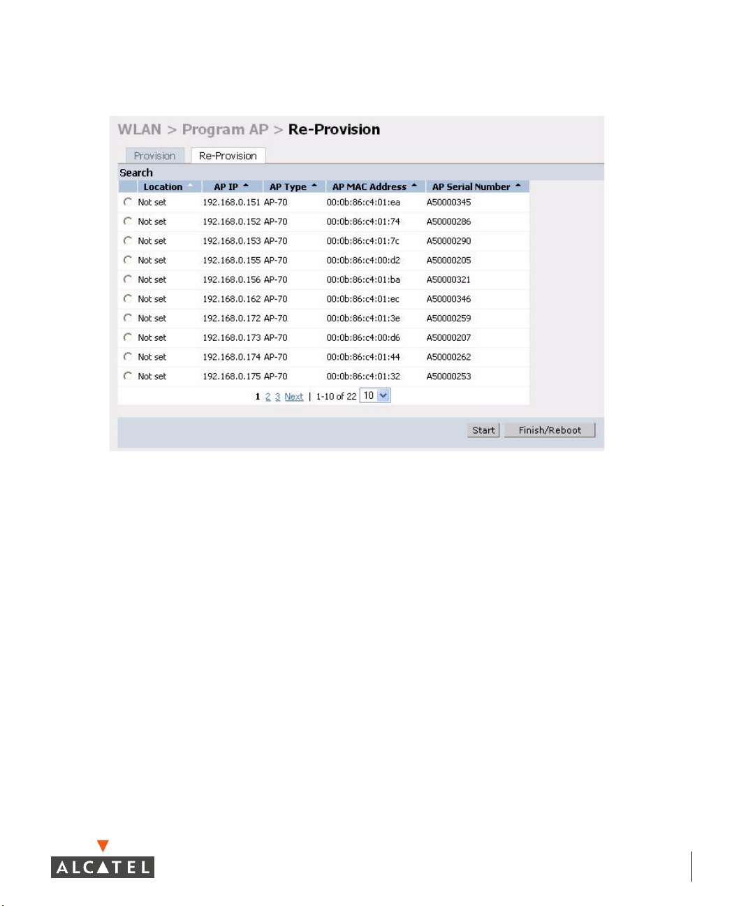
To configure an AP with a unique location code:
z Navigate to the Maintenance > Program AP > Re-provision page.
This page displays a list of APs that have registered with the Master switch
with either their default location code (-1.-1.-1) or their currently configured
location code (if the AP has been provisioned already).
6 Part 031650-00 May 2005
Page 19
Chapter 1
z Select the AP that is to be configured from the list. This can be
selected by using the MAC address of the AP or the serial number
of the AP. Click Enable to start provisioning the AP.
Deploying Access Points 7
Page 20
OmniAccess RN: User Guide
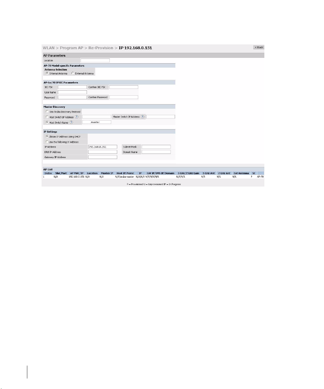
z Enter the location code in the format explained above.
z If the AP being provisioned is a model with detachable antenna
capability (such as an Alcatel AP-60) enter the antenna gain in dBi,
for example 4.0. This is mandatory for all detachable antenna models
as the AP will not will bring up its radio interface or function as an
AP without it.
z Click Apply to apply the configuration to the AP.
NOTE—The configuration does not take effect until the AP is rebooted.
z Navigate to the Maintenance > Reboot AP page.
z Select the AP from the list of the APs and click Reboot to reboot the
AP.
z Navigate to the Maintenance > Program AP > Re-provision page to
confirm that the new settings have taken effect.
8 Part 031650-00 May 2005
Page 21

Chapter 1
Deploying Access Points 9
Page 22

OmniAccess RN: User Guide
10 Part 031650-00 May 2005
Page 23

CHAPTER 2
Secure Remote Access Points
The Secure Remote Access Point Service allows users to connect
APs on remote sites over the Internet to an Alcatel Mobility
Controller. This capability allows remote locations equipped with
Remote Access Points to connect to a corporate office, for
example, over the Internet.
The Remote AP uses L2TP/IPSEC to connect to the Alcatel
Mobility Controller with NAT-T (UDP port 4500 only) support. All
of the AP control traffic and 802.11 data are carried through this
tunnel to the Switch.
Since the Internet is involved, securing data between the AP and
switch becomes key. Also most branch/home office deployments
sit behind a firewall or a NAT device. In case of Remote AP, all
traffic between the switch and the Remote AP is VPN
encapsulated, and all control traffic between the switch and AP
is encrypted. Administrators have a choice of encrypting the data
in addition to the control traffic as additional security.
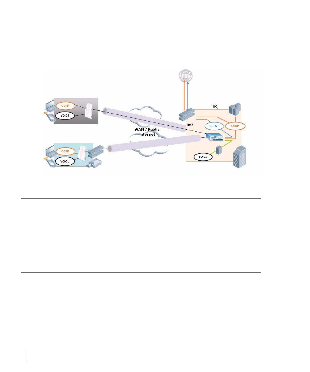
The advantage of using the Secure Remote Access Point Service
as a Remote Access Point is the corporate office is now extended
to the Remote Site. The users can enjoy similar feature sets as the
corporate office users, VoIP application can be extended to
remote sites while the servers and the PBX sit securely in the
corporate office. The corporate network is virtually extended to
the remote user.
Deploying a Branch Office/Home Office Solution
To deploy the Remote AP in a branch office or home office as
shown in the illustration below, the following requirements need
to be met:
Secure Remote Access Points 11
Page 24
OmniAccess RN: User Guide
z The Wireless LAN environment should be a single switch environment.
Future releases of the code are planned to enable multi-switch support and
redundancy.
Securing Communications
The Remote Access Point configurations can also be used to secure control
traffic between the AP and the switch in a corporate environment. In this case,
the AP and switch are in the company’s private address space. The Remote AP
will be similar to the Alcatel AP while tunneling and encrypting all data and
control traffic to the switch.
How the Secure Remote Access Point Service Works
The Secure Remote Access Point Service APs can be deployed in one of the
following ways:
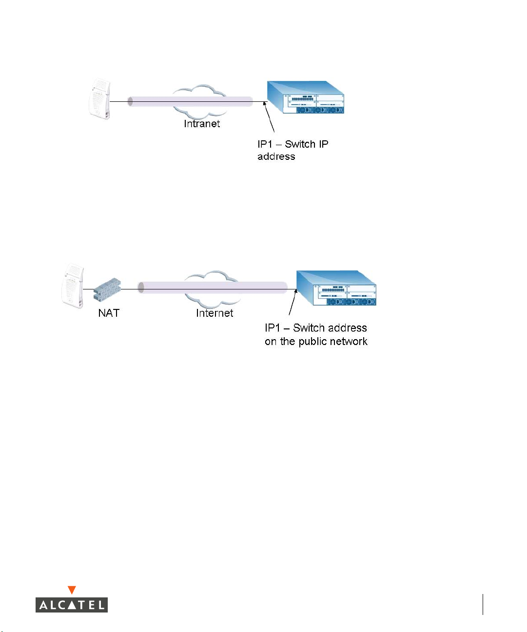
1. The Remote Access Point and switch in a private network which is used to
secure AP-to-switch communication. (Alcatel recommends this deployment
when AP-to-switch communications need to be secured.)
12 Part 031650-00 May 2005
Page 25
Chapter 2
2 The Remote Access Point is on the public network or behind a NAT device
and the switch is on the public network
3 The Remote Access Point is on the public network or behind a NAT device
and the switch is also behind a NAT device. (Alcatel recommends this
deployment for remote access.)
Secure Remote Access Points 13
Page 26
OmniAccess RN: User Guide
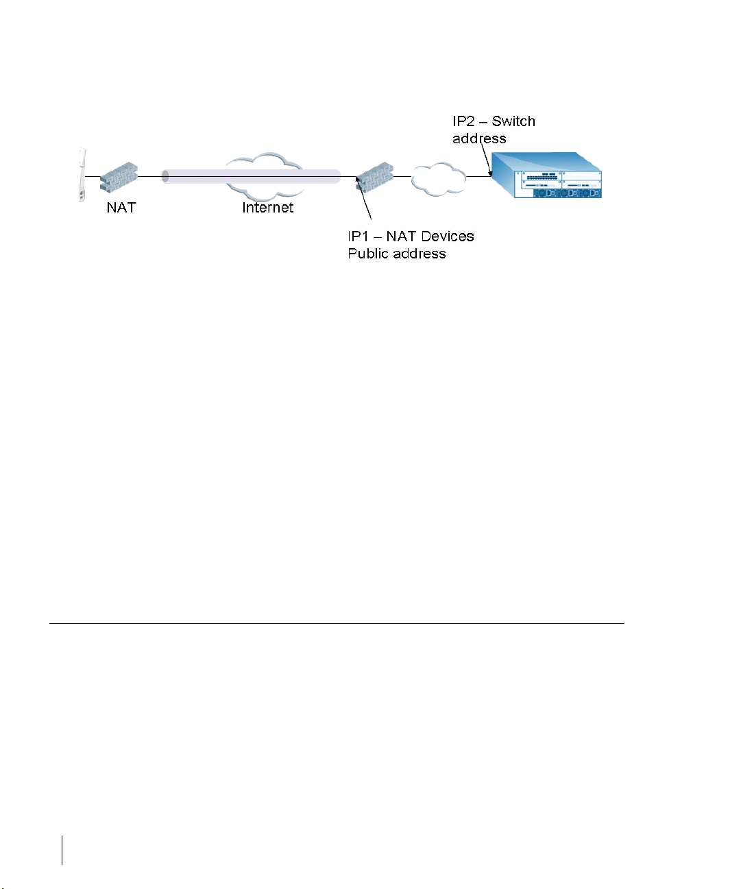
The basic operation for each of these deployments is the same, differing only
slightly in configuration details. The difference in configuration for each of
these deployments will be highlighted in the steps below.
The Secure Remote Access Point Service APs have to be configured with the
tunnel termination address, and address IP1 in the above figures. This address
would be the switch’s IP address, or the NAT device’s public address,
depending on the deployment scenario.
In the case where the switch is behind a NAT device (as in deployment
scenario 3), NAT-T (UDP 4500 port only) needs to be enabled, and all packets
from the NAT device on UDP port 4500 should be forwarded to the Alcatel
Mobility Controller.
The AP uses IP1 to establish a VPN/ IPSec tunnel with the switch. Once the
VPN tunnel is established, the AP bootstraps and becomes operational.
Configuring the Secure Remote Access Point Service
To configure the Secure Remote Gird Point Service (refer to the three
deployment illustrations above):
z Configure the AP as a Remote AP with the master address, the LMP IP, IKE
PSK, and the username and password for authentication.
z Configure IPSec VPN tunnels on the switch the AP will use before it boot-
straps.
z Configure the Secure Remote Access Point Service user role and permis-
sions.
14 Part 031650-00 May 2005
Page 27

z Add the entry for the username/password used for authentication by
Secure Remote Access Point Service to the authentication server.
Configure the NAT device to which the switch connects (deployment scenario
3 only).
These steps are explained below:
1. Configure the AP with the master address, username and password
authentication.
All AP60/61 and AP70 Alcatel Access Points can be provisioned to offer
Secure Remote Access Point Services. The easiest way is to use the Program
AP Web configuration page to configure the AP settings.
z Once the AP boots up, it will appear as an un-provisioned AP if it is a
new AP. If the AP is an already provisioned AP which has to be re-configured to provide Secure Access Point Services, continue with the
next step. Otherwise, navigate to the
sion AP
location and master IP. Apply the changes and reload the AP. This step
ensures that the AP now boots with the 2.4 code (or higher) that supports this feature.
page and provision the AP as you would a regular AP with its
Wireless LAN > Program AP > Provi-
Chapter 2
Deployment Scenario
Deployment 1 Alcatel Mobility Controller IP address
Deployment 2 Alcatel Mobility Controller public IP address
Deployment 3 Public address of the NAT device to which the
Master IP Address Value while
Provisioning the AP
Alcatel Mobility Controller is connected.
Secure Remote Access Points 15
Page 28
OmniAccess RN: User Guide
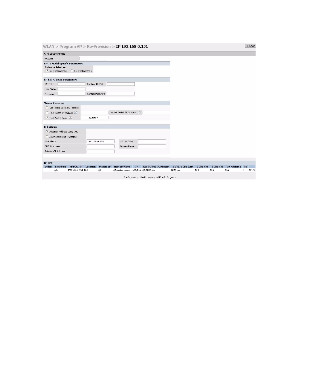
z Select the AP that needs to be configured to provide Secure Access Point
Services on the Program AP > Reprovision page. Configure the AP username
and password, and the IKE PSK for the IPSec settings. Set the master IP to
the public IP address if the AP is connected to the switch over the Internet.
z Regardless of the deployment type, Alcatel recommends that the LMS-IP of
the AP be set to the switch IP address, (either the loopback address of the
switch or the VLAN 1 IP address).
z Navigate to the Configuration > Wireless LAN > Advanced page. Select the AP
to be configured as a Remote Access Point. Configure the LMS-IP to the
Alcatel Wireless LAN switch IP address.
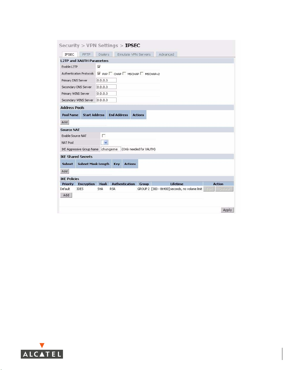
2 Configure the IPSec VPN settings on the switch by navigating to the
uration > Security > VPN Settings > IPSec
16 Part 031650-00 May 2005
page.
Config-
Page 29
Chapter 2
To configure PAP authentication for L2TP:
Make sure that PAP Authentication Protocol is selected. Click
the configuration changes made.
From the CLI enter:
(Alcatel4324)# config t
(Alcatel4324) (config)# vpdn group l2tp
(Alcatel4324) (config-vpdn-l2tp)# ppp authentication PAP
(Alcatel4324) (config-vpdn-l2tp)# exit
(Alcatel4324) (config)#
To configure the L2TP IP pool:
Secure Remote Access Points 17
Apply, to apply
Page 30
OmniAccess RN: User Guide
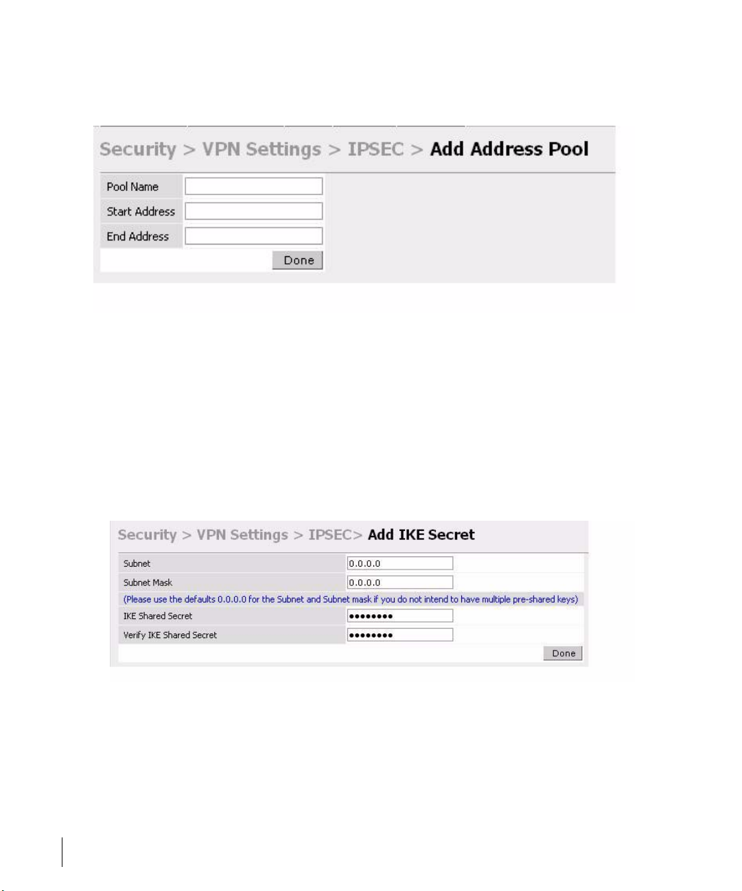
Click Add in the Address Pools panel. Configure the L2TP pool from which the
APs will be assigned addresses.
From the CLI enter:
(Alcatel4324)# config t
(Alcatel4324) (config)#
ip local pool l2tppool1 192.168.69.1 192.168.69.254
(Alcatel4324) (config)#
To configure an ISAKMP encrypted subnet and pre-share key:
Click
Add in the IKE Shared Secrets panel and configure the pre-shared key and
the address pool. For more details, refer to “Configuring Virtual Private
Networks” on page 143.
From the CLI enter:
(Alcatel4324)# configure t
(Alcatel4324) (config)# crypto isakmp key testkey address 0.0.0.0 netmask 0.0.0.0
(Alcatel4324) (config)#
To create an ISAKMP policy:
18 Part 031650-00 May 2005
Page 31

Add in the IKE Policies panel.
Click
Set the priority to 1 and authentication to pre-share on the Add Policy page.
Click Apply to apply the changes made.
Chapter 2
From the CLI enter:
(Alcatel4324)# configure t
(Alcatel4324) (config)# crypto isakmp policy 1
(Alcatel4324) (config-isakmp)# authentication pre-share
(Alcatel4324) (config-isakmp)# exit
(Alcatel4324) (config)
3 Create a user-role for the Remote AP.
Once the remote AP is VPN authenticated successfully, the remote AP is
assigned a role. This role is a temporary role assigned to AP until it completes
the bootstrap process after which it inherits the ap-role. The appropriate ACLs
need to be enabled to permit traffic from the switch to the AP and back to
facilitate the bootstrap process.
From the CLI enter:
(Alcatel6000) #configure terminal
(Alcatel6000) (config) #user-role remote-ap
(Alcatel6000) (config-role) #session-acl allowall
(Alcatel6000) (config-role) #exit
(Alcatel6000) (config) #
The ACLs in this step contain the following rules:
Secure Remote Access Points 19
Page 32

OmniAccess RN: User Guide
(6000) # configure t
(6000) (config) # ip access-list session control
(6000) (config-sess-control)# any any svc-icmp permit
(6000) (config-sess-control)# any any svc-dns permit
(6000) (config-sess-control)# any any svc-papi permit
(6000) (config-sess-control)# any any svc-adp permit
(6000) (config-sess-control)# any any svc-tftp permit
(6000) (config-sess-control)# any any svc-dhcp permit
(6000) (config-sess-control)# any any svc-natt permit
(6000) (config-sess-control)# exit
(6000) (config) # ip access-list session ap-acl
(6000) (config-sess-ap-acl)# any any svc-gre permit
(6000) (config-sess-ap-acl)# any any svc-syslog permit
(6000) (config-sess-ap-acl)# any user svc-snmp permit
(6000) (config-sess-ap-acl)# user any svc-snmp-trap permit
(6000) (config-sess-ap-acl)# user any svc-ntp permit
(6000) (config-sess-ap-acl)# exit
(6000) (config) # ip access-list session ftp-allow
(6000) (config-sess-ftp-allow)# user any svc-ftp permit
(6000) (config-sess-ftp-allow)# exit
4 Add Secure Remote Access Point Service user to the authentication server.
Enable the Alcatel VPN Authentication service. Configure the authentication
server and add the Secure Remote Access Point Service user/password into
the database to allow the Secure Remote Access Point Service user to
authenticate successfully.
20 Part 031650-00 May 2005
Page 33

Chapter 2
If you use the switch local database, navigate to the
page and click Add User.
Add the username and password. If the default VPN role is not the role remote
ap role, then set the role on this page to the remote ap role. Click
apply the changes made.
CAUTION—For security purposes, Alcatel recommends that you use a
unique username/password for each remote AP. You should assign a
unique username and password to each AP.
AAA Servers > Internal DB
Apply to
From the CLI enter:
To specify the role explicitly:
(Alcatel6000) #local-userdb add username remoteap1 password remote role remote-ap
(Alcatel6000)
By default, no authentication server is defined under VPN authentication.
When using VPN authentication, make sure an authentication server is
configured. For example, after adding the username/password in the
appropriate user database, if the user is to use the Internal Server for VPN
authentication, enable this configuration using the following commands:
(Alcatel6000) #configure terminal
(Alcatel6000) (config) #aaa vpn-authentication auth-server Internal
(Alcatel6000) (config) #
Secure Remote Access Points 21
Page 34

OmniAccess RN: User Guide
Also the role created for the Secure Remote Access Point Service in Step 3
needs to be added into aaa vpn-authentication as well by entering:
(Alcatel6000) #configure terminal
(Alcatel6000) (config) #aaa vpn-authentication default-role remote-ap
(Alcatel6000) (config) #
For more information on configuring IPSec and VPNs, see “Configuring Virtual
Private Networks” on page 143 and see “Configuring AAA Servers” on
page 81 for more information on configuring the AAA server.
5 Configuring the NAT device that is connected to the Alcatel Mobility Con-
troller.
The AP and secure switch communication uses the UDP 4500 port. When both
the switch and the AP are behind NAT devices, the AP is configured to use the
NAT device’s public address as its master address. On the NAT device, it is
necessary to enable NAT-T (UDP port 4500 only) and forward all packets to the
public address of the NAT device on UDP port 4500 to the Alcatel Mobility
Controller to ensure that the Remote AP bootstraps successfully.
Double Encryption
The Remote AP control traffic sent to the switch is over an IPSec tunnel. The
user traffic will be encrypted as per the AP/user authentication/encryption
configured. If the administrator wants the user traffic to be further encrypted
using IPSec, then enable double encryption.
(Alcatel4324) (config)# ap location 10.0.0
(Alcatel4324) (sap-config location 10.0.0)# double-encrypt enable
(Alcatel4324) (sap-config location 10.0.0)# exit
(Alcatel4324) (config)#
NOTE—Alcatel recommends that double-encryption not be turned on for
inter-device communication over untrusted networks in AOS-W 2.4 or
higher, as doing so is redundant and adds significant processing overhead
for APs.
22 Part 031650-00 May 2005
Page 35

Managing Software Feature Licenses
This chapter includes the following information:
z Understanding Alcatel software feature licenses
z Installing software feature licenses
z Maintenance of software feature licenses
Alcatel Software Licenses
Alcatel product licenses enable the following software modules:
z Policy Enforcement Firewall (PEF)
z VPN Server (VPN)
z Wireless Intrusion Protection (WIP)
z Advanced AAA (AAA)
z External Services Interface (ESI)
z Client Integrity (CIM)
z xSEC (XSC)
z Remote Access Point (RAP)
Software License Types
For all licensed software modules, two categories of licenses are
available:
1. Permanent license - This type of license permanently
“enables” the desired software module on a specific wireless
LAN switch. Permanent licenses can be obtained through the
sales order process only. Permanent software license
certificates are printed documents, physically mailed to the
user and also accompanied by an email confirmation.
2. Evaluation license - This type of license allows the user to
evaluate the unrestricted functionality of a software module
on a specific wireless LAN switch for 90 days (in 3 x 30 day
increments) without the requirement to purchase a permanent
software license.
Managing Software Feature Licenses 1
Page 36

OmniAccess RN: User Guide
At the end of the 90 day period, a permanent license must be applied to
re-enable this software module on the wireless LAN switch. Evaluation
software license certificates are electronic only and are emailed to the user.
Obtaining a Software License
To obtain either a permanent or evaluation software license, please contact
your sales account manager or authorized reseller. They will process your order
for a permanent license certificate or email an evaluation license certificate to
you as desired.
The Software Licensing Process
Software licenses (permanent or evaluation) are unlocked individually by
module type and are applied to each Alcatel wireless LAN switch as a Software
License Key. Software License Keys are unique alpha-numerical strings created
for individual Alcatel wireless LAN switches and are only valid for the
designated wireless LAN switch.
Certain steps must be taken and criteria met in order to facilitate successfully
enabling software license features on your OmniAccess Wireless LAN switch:
1. Obtain a valid Alcatel Software License Certificate.
2. Locate the Alcatel wireless LAN switch system Serial Number (or
Supervisor Card Serial Number) of the switching platform to which you
wish to apply the software license.
3. Visit the Alcatel Software License Management Web site at
http://eservice.ind.alcatel.com/oaw/
Certificate ID and the System Serial Number to activate a Software License
Key.
4. Log in using the WebUI to the wireless LAN switch on which you wish to
apply the license. Navigate to
the Software License Key and click Apply.
Maintenance > License Management, and enter
login and use the Software License
Software License Certificates
The software license certificate is a software-module and switch-class specific
document (printed or emailed) that states:
z The orderable part number for the license
z A description of the software module type and wireless LAN switch
platform for which it is valid
2 Part 031650-00 May 2005
Page 37

z A unique, 32-character alpha/numerical string that can be used to access
the license management Web site and which, in conjunction with a
wireless LAN switch system / supervisor card serial number, will generate
a unique software license key
FIGURE 2-1 License Certificate
The System Serial Number
The serial number of the unique wireless LAN switch platform for which the
license will be valid for:
z System Serial Number that is specified on the rear of an Alcatel wireless
LAN switch chassis
z System Serial Number of the Supervisor Card (not the chassis) for an
Alcatel modular 6000 series wireless LAN switch platform
z System serial numbers may obtained by physically inspecting the chassis
or card or from the wireless LAN switch WebUI (by navigating to the Switch
> Inventory
page.
Managing Software Feature Licenses 3
Page 38

OmniAccess RN: User Guide
Note that removal of a Supervisor Card is required on a modular platform for
visual inspection and this can result in network down time.
The Alcatel License Management Web Site
In order to activate a Software License Key, you must log in to the Alcatel
License Management Web site at http://eservice.ind.alcatel.com/oaw/.
z If you are a first time user of the licensing site, the Software License
Certificate ID number can be used to log in initially and request a user
account. If you already have a user account, log into the site.
z Once logged in, you will be presented with three options:
1. Activate a Certificate - to activate a new certificate and create the Software
License Key that will be applied to your wireless LAN switch platform
2. Transfer a Certificate - to transfer a Software Certificate ID from one
wireless LAN switch to another (in the event of transferring licenses to a
spares system for example)
3. List Your Certificates - to view all currently available and active Software
License Certificates for your account
To activate a software license certificate, select
certificate ID number, then the System Serial Number of the wireless LAN
switch that you wish to apply the license to. Then click
transaction and the Software License Key will be emailed to you at the email
address you enter at time of license activation.
This Software License Key is only valid for the System Serial Number you
activated it against.
Activate a Certificate, enter the
Activate. A copy of the
Applying The License Key
To “Enable” the software module and functionality, you must now apply the
Software License Key to your Alcatel OmniAccess wireless LAN switch.
1. Using the WebUI, log into your Alcatel OmniAccess wireless LAN switch
with Administrative access rights.
2. Navigate to: Maintenance > License Management where system License
Information and the License Table can be found.
3. Copy the Software License Key that was emailed to you, and paste it into
Add New License Key field. Click Add and Apply to apply the License Key.
the
4 Part 031650-00 May 2005
Page 39

FIGURE 2-2 License Management Screen
4. You must now reboot your wireless LAN switch in order for the new
feature to become available.
Additional Software License Information
Permanent Licenses
Permanent Software Licenses report the software module as Enabled on the
on-switch WebUI. These license types will never expire, even in the event of
the Operating System software being upgraded to a newer version. (Licenses
will carry over one for one).
Evaluation Licenses
Evaluation licenses support the following behavior:
z Evaluation licenses are limited to 3 x 30-day periods. Evaluation licenses
time individually, supporting multiple evaluation licenses for various
software modules each expiring at different times
Managing Software Feature Licenses 5
Page 40

OmniAccess RN: User Guide
z During evaluation, full functionality relating to that software module will be
made available to the user
z During a software evaluation the wireless LAN switch WEB UI will report in
the summary page at initial login that software licenses are expiring
The time remaining on the licensing term displays on the CLI upon login, as
shown below:
(Alcatel6000)
User: admin
Password: *****
NOTICE
NOTICE -- This switch has active licenses that will expire in 29 days
NOTICE
NOTICE -- See 'show license' for details.
NOTICE
(Alcatel6000) >
The WebUI will also display the same information. To view the license
information, click the
Monitoring > Licensing page. The expiration date of trial licenses displays on this
page.
Licensing tab on the main screen, or navigate to the
N
OTE—In the event of multiple evaluation licenses running concurrently on the
same switch, the reported expiration time is the for the licensed feature
with the least amount of duration remaining.
The time remaining on an evaluation license is also logged every day.
6 Part 031650-00 May 2005
Page 41

When each evaluation period expires the following behavior occurs:
z The wireless LAN switch will automatically backup the startup
configuration and reboot itself at midnight (time in accordance with the
system clock)
z All permanently enabled licenses will be unaffected. The expired evaluation
licensed feature will no longer be available, shown as
Expired in the WebUI.
z The Software License Key may be reapplied to the switch, provided the 90
day evaluation time for that feature has not been reached. If the maximum
evaluation time for the evaluation license has been reached, the startup
configuration will still be backed up. However, the feature can now only be
re-enabled with a permanent license key.
Deleting a License Key
To remove a license from a system:
1. Navigate to the
2 Select the feature / Service Type to be removed and click
license keys) or Disable (evaluation license keys)
the License Table.
3 If the feature to be deleted is under the trial period of an evaluation license,
no key will be generated. If the feature is a fully licensed feature, deleting
the feature will result in the feature key being displayed.
Maintenance > License Management page.
Delete (permanent
to the right of the feature entry in
OTE—If you are unable to delete a license key on a disabled or damaged sys-
N
tem that is subsequently returned, you can reinstall this license on
another machine. The factory will take the necessary steps to remove
the license key.
Moving Licenses
It may become necessary to move licenses from one chassis to the other or
simply delete the license for future use. To move licenses, delete the license
from the chassis as described above in “Deleting a License Key ”. Then install
the license on the new switch using that switch’s serial number to generate
the license key.
Switch Resetting
System Reboot
Rebooting or resetting a wireless LAN switch will have no effect on licensing,
whether permanent or evaluation.
Managing Software Feature Licenses 7
Page 42

OmniAccess RN: User Guide
Resetting Switch Configuration
Issuing the write erase command to a switch running software licenses will
not affect the license key management database on the switch, only the
configuration.
Issuing the write erase all command will reset the switch to the factory
default, deleting all on-switch databases including the license key management
database, requiring the system administrator to reinstall all previously installed
license keys.
License Fraud Management
The act of self-moving a license from one switch to another is provided as a
courtesy to allow customers maximum flexibility to manage their organizations
network and sparing at their convenience and with minimal interaction with
Alcatel customer support. License fraud detection is monitored and enforced
by Alcatel. When abnormally high volumes of license transfers for the same
license certificate to multiple switches is experienced, this can indicate breach
of the Alcatel end user software license agreement and will be investigated.
WAR NIN G
When license keys are enabled on an Alcatel OmniAccess wireless LAN switch,
abnormal tampering of the switch’s system clock (setting the system clock
back by 2 hours or more) will result in the “Disabling” of software licensed
modules and their supported features. This can be network service effecting.
Getting Help with Licenses
For information or support with licensing issues, contact your Alcatel sales
representative or log onto the Alcatel license support website at:
http://www.alcatel.com/enterprise/.
8 Part 031650-00 May 2005
Page 43

CHAPTER 3
Configuring Network Parameters
This section outlines the steps involved to configure the various
network parameters required to set up an Alcatel Mobility
Controller. This includes configuring VLANs, IP interfaces, static
routes, and loopback IP addresses.
Conceptual Overview
The concept of VLAN is used in the Alcatel Mobility Controller as
a layer 2 broadcast domain as well as a layer 3 IP interface, similar
to most layer 2/3 switches. The administrator can configure a set
of ports to be members of a VLAN and define an IP
address/netmask for the VLAN interface. A single physical port
can be a member of multiple VLANs by use of 802.1q
trunking/tagging.
The loopback IP address is a logical IP interface that is used by
the Alcatel Mobility Controllers and APs to communicate
amongst each other. To make use of this interface, ensure that
the IP address is reachable through one of the VLAN interfaces.
The examples and configuration guidelines below will illustrate
the same.
Network Configuration
Create/Edit a VLAN
1. Navigate to the Configuration > Switch > VLAN page on the
WebUI.
Configuring Network Parameters 9
Page 44

OmniAccess RN: User Guide
2Click Add to create a new VLAN. To edit an existing VLAN click Edit for this
VLAN. On the next screen (as shown below), enter the VLAN ID, the IP
address and network mask of the VLAN interface. If required, the address of
the DHCP server for that VLAN can also be configured by clicking
The VLAN can be assigned to the required ports by selecting the appropriate boxes in the
procedure for assigning VLANs to ports is explained in the following section.
Assign this VLAN to Ports fields. However, the recommended
Add.
3Click
4 Verify that the VLAN has been created on the VLAN page.
10 Part 031650-00 May 2005
Apply to apply this configuration.
Page 45

Chapter 3
Configuring a Port to Be an Access Port
The in-band Ethernet ports can be configured as access ports and members of
a single VLAN using the following steps:
1. Navigate to the
Configuration > Switch > Port page on the WebUI.
2 Select the port to be configured by clicking on the appropriate box in the
Port Selection section of the page. After selecting the port, choose the
VLAN from the drop down list in the Configure Selected Ports, Enter VLAN(s)
section and click Apply to complete the choice.
Configuring Network Parameters 11
Page 46

OmniAccess RN: User Guide
NOTE—Make sure that the Port Mode is Access in the Configure Selected Ports sec-
tion.
3Click Apply to make this configuration active.
NOTE—This will apply the entire configuration shown in the Configure Selected Ports
section, including changes that were not explicitly made. Make sure that the configuration for all items on the list is as desired before clicking
Apply.
4 Verify that the Configuration was applied by navigating to the Configuration
> Switch > VLAN
screen. The port configured should be shown as a member
of the configured VLAN.
Configuring a Trunk Port
An in-band Ethernet port can be configured to be a trunk port and a member of
multiple VLANs using the following steps:
12 Part 031650-00 May 2005
Page 47

Chapter 3
1. Navigate to the
port(s) to be configured by selecting the appropriate checkbox in the Port
Selection
section.
Configuration > Switch > Port page on the WebUI. Select the
2 Select the
3 Select
desired list of VLANs is different from all configured VLANs, choose the
Allowed VLAN list option and add to the list of allowed VLANs and disallowed VLANs as required.
4Click Apply to apply this configuration.
5 Verify VLAN membership is as configured by navigating to the
> Switch > VLAN
Trunk option to the Port Mode section.
Allow all VLANs to assign all configured VLANs to this port. If the
Configuration
page.
Configuring Network Parameters 13
Page 48

OmniAccess RN: User Guide
Configuring Static Routes
1. Navigate to the Configuration > Switch > IP Routing page.
2Click
3Click
NOTE— The route has not yet been added to the routing table.
Click Apply to add this route to the routing table. The message Configuration
Updated Successfully
Add to add a static route to a destination network or host. Enter the
destination IP and network mask (255.255.255.255 for a host route) and
the next hop IP address.
Add to confirm the entry.
will confirm that the route has been added.
Modifying the Loopback IP Address
NOTE—This procedure requires a switch reboot.
14 Part 031650-00 May 2005
Page 49

To change the switch loopback IP address:
1. Navigate to the
2 Modify the loopback IP address in the Loopback Interface section on this
page as required. Click Apply to apply this configuration.
CAUTION—If you are using the loopback IP address to access the
WebUI, this will result in loss of connectivity. Alcatel recommends
that you use one of the VLAN interface IP address to access the
WebUI to make this change.
Configuration > Switch > General page on the WebUI.
Chapter 3
3 Navigate to the
apply the change of loopback IP address
4Click
Continue to save the configuration.
Maintenance > Switch > Reboot page to reboot the switch to
Configuring Network Parameters 15
Page 50

OmniAccess RN: User Guide
5 When prompted that the changes were written successfully to flash, click
OK.
6 The switch will boot up with the changed loopback IP address.
16 Part 031650-00 May 2005
Page 51

CHAPTER 4
Configuring Redundancy
This chapter outlines the steps required to configure the various
redundancy options available in an Alcatel network. The
redundancy can include backing up an Alcatel Mobility Controller
for the Access Points being controlled (and through them the
clients accessing the wireless network), backing up an Alcatel
Master switch.
Conceptual Overview
The underlying mechanism for the redundancy solutions in the
Alcatel solution is the standard redundancy protocol, Virtual
Router Redundancy Protocol (VRRP). This mechanism can be
used to create various redundancy solutions, including pairs of
local switches acting in an active-active mode or a hot-standby
mode, master backing up a set of local switches, a pair of
switches acting as a redundant pair of master switches in a hot
standby mode. Each of these modes is explained in greater detail
with the required configuration.
VRRP is a protocol that is designed to eliminate the single point of
failure by providing an election mechanism amongst n switches
to elect a “master” switch. This master switch is the owner of the
configured Virtual IP address for this VRRP instance. When the
master becomes unavailable, one of the backup switches takes
the place of the master, thereby getting ownership of the Virtual
IP address. All the network elements (such as the Access Points
and other switches in this case) can be configured to access the
Virtual IP, thereby providing a transparent redundant solution to
the rest of the network.
Configuring Redundancy 17
Page 52

OmniAccess RN: User Guide
Redundancy Configuration
In an Alcatel network, the Access Points are controlled by an Alcatel Mobility
Controller. The APs tunnel all data to the switch that does all the processing of
the data, including encryption/decryption, bridging/forwarding etc.
Local switch redundancy refers to providing redundancy for this switch such
that the APs “failover” to a backup switch if a switch becomes unavailable.
Local switch redundancy is provided by running VRRP between a pair of
Alcatel Mobility Controllers.
OTE—The two switches need to be connected on the same broadcast domain
N
(or layer-2 connected) for VRRP operation. The two switches should be of
the same class (4308 to 4308 or higher), and both switches should be running the same version of AOS-W.
The Access Points are now configured to connect to the “virtual-IP”
configured on the VRRP instance.
Configuring Local Switch Redundancy
To configure redundancy for a local switch:
1. Collect the following information needed to configure local switch
redundancy:
z VLAN ID on the two local switches that are on the same layer 2 net-
work and will be used to configure VRRP.
z Virtual IP address that has been reserved to be used for the VRRP
instance.
2 Navigate to the
the local switches. Click Add to start creating a VRRP instance.
Configuration > Switch > VRRP page on the WebUI for each of
18 Part 031650-00 May 2005
Page 53

Chapter 4
3 Enter the various VRRP parameters for the VRRP instance. The table below
explains what each of the parameters means and the recommended/expected values for this configuration.
Parameter Explanation
Virtual Router
ID
Advertisement
Interval
Authentication
Password
This is the Virtual Router ID
that uniquely identifies this
VRRP instance.
This is the interval between
successive VRRP
advertisements sent by the
current master
This is an optional password
that can be used to
authenticate VRRP peers in
their advertisements
Description This is an optional textual
description to describe the
VRRP instance
IP Address This is the Virtual IP address
that will be owned by the
elected VRRP master.
Expected/Recommended
Values
Recommended to configure
this with the same value as the
VLAN ID for easy
administration.
Recommended to leave as
default (1000ms = 1s).
A password of up to 8
characters length can be
configured in this field or it can
be left empty to take the
default of no authentication
password.
Configure this with the Virtual
IP address reserved in step i.
Configuring Redundancy 19
Page 54

OmniAccess RN: User Guide
Enable Router
Pre-emption
Priority Priority level of the VRRP
Admin State Administrative state of the
VLAN VLAN on which the VRRP
4 Configure the values in the respective fields as shown in the table above
and click Add to enter the values.
Selecting this option means
that a switch can take over
the role of master if it detects
a lower priority switch
currently acting as master
instance for the switch. This
value is used in the election
mechanism for the master
VRRP instance
protocol will run.
For this topology it is
recommended NOT to select
this option.
It is recommended to leave this
as the default for this
topology.(default = 100).
To start the VRRP instance,
change the admin state to UP.
Configure this to be the VLAN
ID from step i.
5Click
20 Part 031650-00 May 2005
Apply to apply the configuration and add the VRRP instance.
Page 55

6 Configure the Access Points to terminate their tunnels on the Virtual-IP
address. This can be done with greater flexibility and ease from the CLI.
The APs can be identified by their location code (building.floor.location)
with 0 being used as a wild card for any of the values. Thus a location code
of 10.0.0 would refer to all the APs in building 10. Refer to the AP provisioning guide for directions on how to provision the APs with their location
codes.
Chapter 4
NOTE—This command needs to be executed on the Master switch as only the
Master switch controls all APs in the network.
Use the steps in the table below to configure the “lms-ip” for a set of AP(s).
Command Purpose
Step 1 configure terminal Enter the global configuration mode.
Step 2 ap location b.f.l Use the location code value to select
set of AP(s) to configure.
Step 3 lms-ip ip-address Configure the lms-ip for the selected
set of APs.
The example below shows how the steps shown above can be used to configure the lms-ip for all APs in building 10:
Configuring Redundancy 21
Page 56

OmniAccess RN: User Guide
(Alcatel4324) (config) #ap location 10.0.0
(Alcatel4324) (sap-config location 10.0.0) #lms-ip 10.200.11.254
(Alcatel4324) (sap-config location 10.0.0) #
Master Switch Redundancy
The Master switch in the Alcatel solution acts as a single point of configuration
for global policies such as firewall policies, authentication parameters, RF
configuration to ease the configuration and maintenance of a wireless
network. It also maintains a database related to the wireless network that is
used to make any adjustments (automated as well as manual) in reaction to
events that cause a change in the environment (such as an AP becoming
unavailable). The Master switch is also responsible for providing the
configuration for any AP to complete its boot process. If the Master becomes
unavailable, the network continues to run without any interruption. However
any change in the network topology or configuration will require the availability
of the Master switch.
To maintain a highly redundant network, the administrator can use a switch to
act as a hot standby for the Master switch. The underlying protocol used is the
same as in local redundancy, that is VRRP.
To configure master switch redundancy:
1. Collect the following data before configuring master switch redundancy.
z VLAN ID on the two switches that are on the same layer 2 network and
will be used to configure VRRP.
z Virtual IP address that has been reserved to be used for the VRRP
instance
2 Connect to the switch CLI using Telnet or SSH. After logging into the
switch, enter the global configuration mode.
To configure VRRP on the VLAN ID.
22 Part 031650-00 May 2005
Page 57

Chapter 4
Command Explanation
Step 1 vrrp vrrp-id Creates the VRRP
instance.
Step 2
Step 3
Step 4 priority priority-value Priority of the
vlan vlan-id Associates the
VRRP instance
with a VLAN.
ip address ip-address Virtual IP address
for the VRRP
instance
VRRP instance
that is used in
the election of
the master. By
default, the value
is 100.
Expected/Recommen
ded Values
It is recommended to
configure the VRRP ID
to be the same as VLAN
ID on which the
instance runs for easier
administration and
maintenance.
VLAN ID from step i.
Virtual IP address from
step i.
The following are the
recommended values
for the priority on the
“initially preferred”
master and “initially
preferred” backup
switches:
Master: 110
Step 5 preempt Enable
preemption
Backup: 100
Note: these values are
closely related to the
value of the value to be
added to the priority by
tracking in step 7.
Configuring Redundancy 23
Page 58

OmniAccess RN: User Guide
Step 5 authentication password
(Optional)
Step 6
description description
(Optional)
Step 7
Step 8 no shutdown Administratively
tracking master-up-time
duration add value
Optional
authentication
password that is
used to
authenticate
packets between
VRRP peers
Optional
description to the
VRRP instance.
Configures a
tracking
mechanism that
adds value to the
priority after a
switch has been
the master for
the VRRP
instance for a
duration longer
than the
configured value
duration. This is
used to avoid
failing over to a
backup Master
for transient
failures.
enables the VRRP
instance.
Any password of up to
8 characters can be
configured on both the
peer switches. This is
an optional
configuration.
Any text description can
be configured in this
field. This is an optional
configuration.
The value of duration is
the length of time that
the administrator
expects will be long
enough that the
database gathered in
the time is too
important to be lost.
This will obviously vary
from instance to
instance.
The recommended value
of value in conjunction
to the values for priority
in step 4 is 20.
N/A.
The following shows an example of the configuration on the “initially-preferred
master”.
(Alcatel4324) (config) #vrrp 22
(Alcatel4324) (config-vrrp) #vlan 22
(Alcatel4324) (config-vrrp) #ip address 10.200.22.254
(Alcatel4324) (config-vrrp) #priority 110
(Alcatel4324) (config-vrrp) #preempt
(Alcatel4324) (config-vrrp) #authentication password
(Alcatel4324) (config-vrrp) #description Preferred-Master
24 Part 031650-00 May 2005
Page 59

(Alcatel4324) (config-vrrp) #tracking master-up-time 30 add 20
(Alcatel4324) (config-vrrp) #no shutdown
The following shows the corresponding VRRP configuration for the peer
switch.
(Alcatel4324) (config) #vrrp 22
(Alcatel4324) (config-vrrp) #vlan 22
(Alcatel4324) (config-vrrp) #ip address 10.200.22.254
(Alcatel4324) (config-vrrp) #priority 100
(Alcatel4324) (config-vrrp) #preempt
(Alcatel4324) (config-vrrp) #authentication password
(Alcatel4324) (config-vrrp) #description Backup-Master
(Alcatel4324) (config-vrrp) #tracking master-up-time 30 add 20
(Alcatel4324) (config-vrrp) #no shutdown
Use the following steps to associate the VRRP instance with master switch
redundancy.
Chapter 4
Command Explanation
Step 1 master-redundancy Enter the
master-redundancy
context
Step 2
Step 3 peer-ip-address ip-address Loopback IP address
master-vrrp vr-id Associates a VRRP
instance with master
redundancy
of the peer for
master redundancy
Expected/recommen
ded Values
N/A
VR-ID of the VRRP
instance configured in
step iii.
Loopback IP address of
the peer switch.
Configuring Redundancy 25
Page 60

OmniAccess RN: User Guide
NOTE—Note: All the APs and local switches in the network should be config-
ured with the Virtual IP address as Master IP. The Master IP address can be
configured for local switches during the Initial Setup Dialog (refer Quick Start
Guide for more details). The administrator can also use the following commands to change the Master IP of the local switch. The switch will require a
reboot after changing the Master IP of the switch.
Command Explanation
Step 1 masterip ip-address Configures the Master IP
address of a local switch
If DNS resolution is the chosen mechanism for the APs to discover their
Master switch, ensure that the name “Alcatel-master” resolves to the same
Virtual IP address configured as a part of the master redundancy.
Expected/recomm
ended values
Configure this to be
the virtual IP
address of the VRRP
instance used for
master redundancy.
Master-Local Switch Redundancy
This section outlines the concepts behind a redundancy solution where a
master can act as a backup for one or more local switches and shows how to
configure the Alcatel Mobility Controllers for such a redundant solution. In this
solution, the local switches act as the controller for the APs. When any one of
the local switches becomes unavailable, the master takes over the APs
controlled by that local switch for the time that the local switch remains
unavailable. It is configured such that when the local switch comes back again,
it can take control over the APs once more.
This type of redundant solution is illustrated by the following topology
diagram.
OTE—This solution requires that the master switch has a layer-2 connectivity
N
to all the local switches.
26 Part 031650-00 May 2005
Page 61

Chapter 4
Master
VLAN 1, 2, .... n
Layer 2
Network
VLAN 1
VLAN 2
Local 1
In the network shown above, the master switch is layer 2 connected to the
local switches on VLANs 1, 2… n respectively. To configure redundancy as
described in the conceptual overview for master-local redundancy, configure
VRRP instances on each of the VLANs between the master and the respective
local switch. The VRRP instance on the local switch is configured with a
higher priority to ensure that when available, the APs always choose the local
switch to terminate their tunnels.
To configure the master and local switches for such a topology:
1. Configure the interface on the master switch to be a trunk port with 1, 2…
n being member VLANs. Refer to the “Configuring Network Parameters” for
more details on how to configure this.
2 Collect the following data before configuring master switch redundancy.
Local 2 Local n
Redundant Topology:
Master-Local redundancy
VLAN n
z VLAN IDs on the switches corresponding to the VLANs 1, 2…n shown
in the topology above.
z Virtual IP addresses that has been reserved to be used for the VRRP
instances.
3 Connect to the switch CLI using Telnet or SSH. After logging into the
switch, enter the global configuration mode.
Configuring Redundancy 27
Page 62

OmniAccess RN: User Guide
4 Use the following steps to configure VRRP on the master and local
switches respectively. Note: the master switch will be configured for a
number of VRRP instances (equal to the number of local switches the master is backing up).
Command Explanation
Step 1 vrrp vrrp-id Creates the VRRP
instance.
Step 2
Step 3
Step 4 Priority priority-value Priority of the VRRP
Step 5 Preempt Enable preemption
vlan vlan-id Associates the
VRRP instance with
a VLAN.
ip address ip-address Virtual IP address
for the VRRP
instance
instance that is
used in the election
of the master. By
default, the value is
100.
Expected/Recommen
ded Values
It is recommended to
configure the VRRP ID to
be the same as VLAN ID
on which the instance
runs for easier
administration and
maintenance.
VLAN ID from step 2
above.
Virtual IP address from
step 2 above.
The following are the
recommended values for
the priority on the
master and local
switches:
Master: 100
Local: 110.
28 Part 031650-00 May 2005
Page 63

Chapter 4
Step 5 authentication
password (Optional)
Step 6
description description
(Optional)
Step 7 no shutdown Administratively
The following shows an example configuration of the Master switch in such a
topology for one of the VLANs (in this case VLAN 22).
Optional
authentication
password that is
used to
authenticate
packets between
VRRP peers
Optional
description to the
VRRP instance.
enables the VRRP
instance.
Any password of up to 8
characters can be
configured on both the
peer switches. This is an
optional configuration.
Any text description can
be configured in this
field. This is an optional
configuration.
N/A.
(Alcatel4324) (config) #vrrp 22
(Alcatel4324) (config-vrrp) #vlan 22
(Alcatel4324) (config-vrrp) #ip address 10.200.22.254
(Alcatel4324) (config-vrrp) #priority 100
(Alcatel4324) (config-vrrp) #preempt
(Alcatel4324) (config-vrrp) #authentication password
(Alcatel4324) (config-vrrp) #description
Master-acting-as-backup-to-local
(Alcatel4324) (config-vrrp) #tracking master-up-time 30 add 20
(Alcatel4324) (config-vrrp) #no shutdown
The following shows the configuration on the corresponding local switch.
(Alcatel4324) (config) #vrrp 22
(Alcatel4324) (config-vrrp) #vlan 22
(Alcatel4324) (config-vrrp) #ip address 10.200.22.254
(Alcatel4324) (config-vrrp) #priority 110
(Alcatel4324) (config-vrrp) #preempt
(Alcatel4324) (config-vrrp) #authentication password
(Alcatel4324) (config-vrrp) #description local-backed-by-master
(Alcatel4324) (config-vrrp) #no shutdown
Configuring Redundancy 29
Page 64

OmniAccess RN: User Guide
Configure the APs with the appropriate Virtual-IP address depending on which
switch is expected to control the AP. As an example, the administrator can
configure such that all APs on floor 1 are controlled by local switch 1, all APs
on floor 2 are controlled by local switch 2 and so on. All the local switches are
backed up by the master switch as shown above. In such a case, configure all
APs on floor 1 to be controlled by the Virtual IP address of the VRRP between
local switch 1 and master and so on. This can be done by following these
steps:
Command Explanation
Step 1 ap location b.f.l Choose the APs to
configure by using the
location code in the
building.floor.location
format.
Expected/recommend
ed values
Depending on the set of
APs to be configured,
enter the location code
using 0 as a wild card
value. As an example all
APs on building 1 and
floor 1 can be
represented by the
location code 1.1.0.
Step 2 lms-ip ip-address Configure the IP
address of the switch
controlling the APs
chosen
Configure this IP address
to be the same as the
Virtual IP address for the
VRRP instance between
the appropriate local
switch and master
switch.
The following example shows how these steps are used to configure the APs on
floor 1 of building 1 to use the pair of switches configured in the above example.
N
OTE—This command is executed on the Master switch.
(Alcatel4324) (config) #ap location 1.1.0
(Alcatel4324) (sap-config location 1.1.0) #lms-ip 10.200.11.254
(Alcatel4324) (sap-config location 1.1.0) #
30 Part 031650-00 May 2005
Page 65

CHAPTER 5
Adding a Local Switch
This chapter explains how to expand your network by adding a
local switch to a master switch configuration. Typically, this is
the first expansion of the network beyond a network with just
one switch (which is a master switch by default). This chapter is
a basic-level discussion of creating master-local switch
configurations. More complicated multi-switch configurations are
discussed in other chapters. For example, for information on
configuring redundant switches, see “Configuring Redundancy”
on page 17.
A single Wireless LAN configuration, the master switch is the
switch which controls the RF and security settings of the
Wireless LAN network. Additional switches to the same Alcatel
Wireless LAN will serve as local switches to the master switch.
The local switch operates independently of the master switch and
depends on the master switch only for its security and RF
settings (the global settings across the network like RF, user
policies, and authentication settings). The Layer-2 and Layer-3
configurations are configured on the local switch and are
independent of the master switch. The local switch needs to have
connectivity to the master switch at all times to ensure that any
changes on the master are propagated to the local switch.
Some of the common reasons to move from a single to a multi
switch-environment include:
z
Scaling to include a larger coverage area
z Setting up a branch office switch
z Network requirements to re-distribute APs from a single
switch to multiple switches
The addition of a local switch could also become necessary
depending on the network setup and connectivity specific to the
network topology at hand.
Adding a Local Switch 31
Page 66

OmniAccess RN: User Guide
Configuring Local Switches
A single master configuration can be one with one switch, the master switch
or a master redundant configuration with one master switch and the VRRP
redundant backup switch. This section will highlight the difference in
configuration for both of these scenarios.
The steps involved in migrating from a single to a multi-switch environment
are:
1. Configure the local switch to point to the master switch IP.
2 Configure the Layer-2 / Layer-3 settings on the local switch (VLANs, IP
subnets, IP routes).
3 Configure the ports the master and local switch will use to communicate
with each other to be trusted ports.
4 Configure the LMS-IP to point to the new local switch for those APs that
need to boot off the local switch.
5 Reboot the APs if they are already on the network, so that they now con-
nect to the local switch.
These steps are explained below.
Configuring the Local Switch
There are multiple ways of doing this, using the startup dialog or the web
interface.
Using the Setup Dialog
When you power up an unconfigured Alcatel Mobility Controller, or reboot a
configured Alcatel Mobility Controller after executing a write erase, reload
sequence, you see the following setup dialog (using an Alcatel 4324 as an
example):
32 Part 031650-00 May 2005
Page 67

Enter system name [Alcatel4324]:
Enter VLAN 1 interface IP address [172.16.0.254]: 10.200.14.6
Enter VLAN 1 interface subnet mask [255.255.255.0]:
Enter IP Default gateway [none]: 10.200.14.1
Enter Switch Role, (master|local) [master]: local <-----
Enter Master switch IP address: 10.4.21.10 <-----
Enter password for admin login (up to 32 chars): *****
Re-type Password for admin login: *****
Enter password for enable mode (up to 15 chars): ******
Re-type password for enable mode: ******
Do you wish to shutdown all the ports (yes|no)? [no]:
Current choices are:
System name: Alcatel4324
VLAN 1 interface IP address: 10.100.2.30
VLAN 1 interface subnet mask: 255.255.255.0
IP Default gateway: 10.100.2.1
Switch Role: local
Master switch IP address: 10.200.14.6
Ports shutdown: no
If you accept the changes the switch will restart!
Type <ctrl-P> to go back and change answer for any question
Do you wish to accept the changes (yes|no)y
Creating configuration... Done.
System will now restart!
Chapter 5
When prompted to enter the operational mode in the setup dialog, enter
local to set the switch operational mode to be a local switch.
You are then prompted for the master switch IP address. Enter the IP address
of the master switch of the Wireless LAN network.
Using the Web UI
Once the switch is up and operation with Layer-3 connectivity, the following
needs to be configured to set the switch up as a local switch:
z The mode of the switch has to be set to local.
Adding a Local Switch 33
Page 68

OmniAccess RN: User Guide
The master IP address is the IP address of the master switch. If master
redundancy is enabled on the master, this address should be the VRRP
address for the VLAN instance corresponding to the switch IP.
34 Part 031650-00 May 2005
Page 69

Configuring the L2 / L3 Settings
The VLANs, subnets, and IP address on the local switch need to be
configured on the local switch for IP connectivity. (Refer to “Configuring
Network Parameters” on page 9.)
Verify connectivity to the master switch by pinging the master switch from
the local switch.
On the master switch ensure that the master switch recognizes the new
switch as its local switch.
Chapter 5
The local switch will be listed with type
Controllers
and local switches to sync up configurations.
page on the master. It will take about 4 – 5 minutes for the master
local in the All Alcatel Mobility
Configuring Trusted Ports
Navigate to the Configuration > Switch > Port page and make sure that the port
on the local switch connecting the master is trusted. Repeat for the port on
the master switch connecting to the local switch.
Configure the APs
For APs that will boot off of the local switch, you must configure the LMS-IP
address. This configuration has to be done on the master switch. When the
changes are applied, the master switch will push out these configurations to
the local switch.
1. Navigate to the Wireless LAN > Advanced > General page. Select the AP that
has to bootstrap from the local switch.
2 Configure the LMS-IP for the APs under the AP’s location ID on the master.
3 Apply the configuration on the master.
Adding a Local Switch 35
Page 70

OmniAccess RN: User Guide
NOTE—To verify that the local switch has obtained a copy of the global set-
tings, check the local switch for the global config changes made on
the master like authentication changes, WMS settings.
Reboot the APs
The configuration changes take effect only after rebooting the affected APs
which allows them to reassociate with the local switch. In the example above,
AP 1.1.20 will be rebooted. After rebooting, these APs appear to the new
switch as local APs.
36 Part 031650-00 May 2005
Page 71

Chapter 5
Adding a Local Switch 37
Page 72

OmniAccess RN: User Guide
38 Part 031650-00 May 2005
Page 73

CHAPTER 6
Configuring Wireless LANs
This document details the Wireless LAN configuration using the
GUI or the web interface.
Conceptual Overview
The Wireless LAN configuration page is primarily used to set the
802.11 related parameters such the SSID, encryption methods,
transmit powers, to name a few. The following section walks the
user through the basic 802.11 configurations.
The web interface classifies the Wireless LAN configurations into
3 major categories
z Network—The global Wireless LAN configurations can be done
under this section
z Radio—The radio configurations for the .11a and g radio can
be done under this section.
z Advanced—This section is primarily used for Access Points
having unique configurations that are different from the global
settings.
The first few sections deal with the configurations procedures.
The last section consists of examples.
Configuring Wireless LANs 39
Page 74

OmniAccess RN: User Guide
Configuring Wireless LAN—802.11 Networks
Pre-requisites
Before configuring a new SSID or editing an SSID setting, you should have the
following information regarding the SSID. (This is not mandatory and you can
return to these pages to modify the configuration at any time.)
Multiple SSIDs can be configured per AP. When doing so each of the following
fields needs to be configured for each SSID separately.
Parameter Definition Explanation
SSID
Radio type
SSID Default Vlan
Encryption type
WEP
TKIP
The SSID of the
network
Choose the radio
types to apply the
configurations. a, b/g,
a/b/g.
The VLAN that would
be assigned to the
user associating to
this SSID. The VLAN
should exist at the
time of Wireless LAN
configuration.
WEP or TKIP or None.
Static WEP or
Dynamic WEP.
PSK or WPA. If PSK, hex or passphrase
a, b/g, a/b/g.
If Static WEP, the hex key
(10 / 24 character size).
Hex key should 64
characters in length.
Passphrase should be 3-63
ascii characters in length.
40 Part 031650-00 May 2005
Page 75

Chapter 6
AES-CCM
Mixed TKIP/AES-CCM
Reply to Broadcast
probe requests
1. Navigate to the
Advanced Encryption
Standard (AES) in
Counter with
CBC-MAC (CCM)
Mode
Combined TKIP and
AES-CCM
Whether the AP
should respond to
broadcast probe
request with this
SSID.
Configuration > Wireless LAN > Network page.
2 To add a new SSID, click
configuration page appears.
NOTE—The default SSID present is Alcatel-ap. This will be broadcast as a valid
SSID if the value is not changed This is the only SSID that permits the
change of the SSID name.
Add. To edit an existing SSID click Edit. The SSID
Configuring Wireless LANs 41
Page 76

OmniAccess RN: User Guide
SSID
Radio Type
Encryption type
SSID Default VLAN
Ignore Broadcast
Probe Request
Enter the SSID name used by the wireless clients to
associate. The SSID is case sensitive.
Specify the radio type that this SSID will be applied to.
This can be applied to the a network only, the b/g
network only or to a nd b/g by making the appropriate
selection from the pull down menu.
This can be:
NULL - without any encryption, open system
WEP
TKIP
AES-CCM
Mixed TKIP/AES-CCM
The VLAN that will be assigned to the wireless users
after they associate to the SSID. The value for the VLAN
can be selected from the pull down menu and the “< -- “
should be clicked on for the changes to the VLAN
selection to be applied.
Select this checkbox to prevent the AP from responding
back with this SSID to broadcast requests. If this is
checked the clients will have to configure the SSID on
their client utility to associate with this SSID.
DTIM Period
42 Part 031650-00 May 2005
Delivery Traffic Indication Message.
Page 77

Once the selection is made, the corresponding dialog windows will
open to allow the user to configure as per the selection.
Configuring NULL Encryption
If the encryption type selected is null or the open system then there will be no
encryption. The packets between the AP and the client would be in clear text.
Click the Apply tab to apply the configuration changes made and to prevent
loss of work before navigating to other pages.
Configuring WEP Encryption
Chapter 6
z Select the radio button to enable WEP encryption. This opens the WEP
encryption dialog
z Select Static WEP or dynamic WEP.
z If Static WEP is selected, the user will have to enter a hex key that
would have to configured on the client.
z Click the Use as Tx Key radio button corresponding to the S. No of the
key to be used.
Configuring Wireless LANs 43
Page 78

OmniAccess RN: User Guide
z From the pull down menu select the key size – 10 hex characters or 26
Hex Characters.
z Type in the key as per the selection made. The characters should belong
to the set [0, 1, 2, 3, 4, 5, 6, 7, 8, 9, a, b, c, d, e, f]. The keys are case
insensitive.
z Click Apply to apply the configuration changes made and to prevent
loss of work before navigating to other pages.
Configuring TKIP Encryption
z Select the radio button to enable TKIP encryption. This opens the TKIP
dialog.
z Select PSK TKIP for static TKIP key configuration and WPA TKIP for
dynamic TKIP.
z If PSK TKIP is selected, the key can be hex or ASCII. Enter a 64 charac-
ter hex key or a 8 – 63 character ASCII key.
z From the pull down menu select the key size – 10 hex characters or 26
Hex Characters.
z Type in the key as per the selection made. The characters should belong
to the set [0, 1, 2, 3, 4, 5, 6, 7, 8, 9, a, b, c, d, e, f]. The keys are case
insensitive.
z Click Apply to apply the configuration changes made and to prevent
loss of work before navigating to other pages.
Configuring AES-CCM Encryption
NOTE—AES-CCM was formerly referred to as AES-CCMP.
44 Part 031650-00 May 2005
Page 79

Chapter 6
z Select the radio button to enable AES-CCM encryption. This opens the
WPA2 dialog.
z Select PSK AES-CCM for static PSK AES key configuration and WPA2
AES-CCM for dynamic AES.
z If PSK AES-CCM is selected, the key can be hex or ASCII. Enter a 64
character hex key or a 8 – 63 character ASCII key.Valid characters are
letters and numbers but not spaces, dashes, commas, colons are other
punctuation characters.
z Click Apply to apply the configuration changes made and to prevent
loss of work before navigating to other pages.
Configuring Wireless LANs 45
Page 80

OmniAccess RN: User Guide
Configuring Mixed TKIP and AES Encryption
z Select the radio button to enable TKIP/AES-CCM encryption. This opens
the Mixed TKIP/AES-CCM dialog.
z Select PSK TKIP/AES-CCM for static TKIP and AES key configuration or
WPA/2 TKIP/AES-CCM for dynamic TKIP and AES.
z If PSK TKIP/AES-CCM is selected, the key can be hex or ASCII. Enter a
64 character hex key or a 8 – 63 character ASCII key.
z Click Apply to apply the configuration changes made and to prevent
loss of work before navigating to other pages.
3 To configure multiple SSID, click
above.
4 To modify the SSID name – The default SSID is the only SSID that permits
the changing of the SSID name. To change the SSID but retain the configurations:
Add and repeat the steps mentioned
z Create a new SSID with the desired name and settings.
z Delete the existing SSID entry.
5 To configure the general parameters like the SNMP System, Trap receivers,
SNMP users navigate to the
Wireless LAN > Network > General page.
46 Part 031650-00 May 2005
Page 81

Chapter 6
6 Configure the LMS address
The AP can bootstrap with any switch on the Wireless LAN network (in a setup
with master and local switches), if all of the switches are on the same VLAN,
and if load balancing is enabled on the switches. To force the AP to bootstrap
with a particular switch the lmsip is configured with the IP address of the
desired switch. The AP is then forced to bootstrap with that switch.
z Navigate to the Wireless LAN > Network > General page.
z Configure the LMS IP address
z Click Apply for the change to take effect.
Configuring Wireless LANs—Radio Configuration
The radio settings can be fine tuned using the Web interface. (Selecting these
options may affect roaming performance.)
1. Navigate to the
2 In case of AP, set the Max Clients to the maximum number of clients that
the AP can support. Ideal setting is 20.
3 Check the Initial Radio State Up button to ensure that the AP radio is up on
reboot.
Configuration > Wireless LAN > Radio > 802.11b/g page.
4 Check the Deny Broadcast Enable checkbox to disable probe replies. Oth-
erwise, check
5 Check Hide SSID to exclude including the SSID in periodic beacons.
6 Set the Mode to Access Point to use the AP as an Access Point. If the AP
needs to operate as an Air monitor, check the Air Monitor checkbox under
Mode.
Disable.
Configuring Wireless LANs 47
Page 82

OmniAccess RN: User Guide
7 Check Apply to apply the changes before navigating to other pages to pre-
vent loss of configuration.
8 The above configuration can be created for 802.11a by navigating to the
Configuration > Wireless LAN > Radio > 802.11a page.
48 Part 031650-00 May 2005
Page 83

Configuring Wireless LANs—Advanced
While the above two sections deal with global AP configurations, individual
AP can be configured with specific settings using the Advanced tab under
Wireless LAN. Each of the APs are identified by unique locations and these
locations are used to configure the AP uniquely.
The global configurations will be overridden by the location specific
configurations.
1. Navigate to the
Configuration > Wireless LAN > Radio > Advanced page..
Chapter 6
2Click
3 Enter a location ID of the format <bldg.floor.plan> where each of these is an
4Click
Add to add a new location.
integer.
Add to add the location. Once the location ID is entered and applied,
the global configuration if any will get inherited to the location
Configuring Wireless LANs 49
Page 84

OmniAccess RN: User Guide
The configuration of the specific location can be customized by adding SSIDs
and configuring the radios as required by selecting the tabs on the page. To
add a new SSID:
1. Click
Add and configure the SSID similar to configuring the 802.11
Networks.
2 All radio configurations for the location can also be made by selecting the
802.11b/g or the 802.11a tab
3 Apply the configurations for the configurations to take effect.
50 Part 031650-00 May 2005
Page 85

Example
The following example includes:
z A a/b/g SSID called Alcatel with dynamic WEP
z A b/g SSID called voice with static WEP
z The AP in location 4.2.6 is set to have guest SSID in addition to the other
two SSID. The guest SSID is open
1. Configure the a/b/g SSID Alcatel in the global location 0.0.0 with dynamic
WEP.
Alcatel
Chapter 6
2 Configure the b/g voice SSID in the global location 0.0.0
Configuring Wireless LANs 51
Page 86

OmniAccess RN: User Guide
3 Configure the guest SSID for location 1.10.2
z Add the location 1.10.2.
52 Part 031650-00 May 2005
Page 87

z Once the location is added, the location page is opened up with the
inherited SSID. Click Add to add a new SSID guest.
z Configure the SSID with open system and native VLAN for the guest
users to be the required VLAN.
Chapter 6
Adaptive Radio Management
Adaptive Radio Management (ARM) is the next generation RF resource
allocation algorithm in AOS-W. ARM is an enhancement to Auto-RRA
functionality and performance.
ARM is the state of the art RF management technology for a stable, self
healing RF design. ARM takes the distributed algorithm approach allowing
APs to decide their transmit power and channel settings based on what they
hear in the air. The APs make their channel/power setting decisions based on
Configuring Wireless LANs 53
Page 88

OmniAccess RN: User Guide
the RF environment as they hear it, independent of the switch. This results in a
highly scalable and reliable RF environment while also significantly reducing
the time the AP takes to adapt to the changing RF environment.
The APs scan all valid channels (channels in the regulatory domain) at regular
intervals and compute the following metrics per channel:
z Coverage index: Signal to noise ratio for all valid APs
z Interference index: Signal to noise ratio for all APs
These metric are used by the APs to decide the best channel and transmit
power settings for optimal coverage.
Deciding the Channel Setting
In addition to the interference index, the APs use the free-channel index for
deciding the optimal channel setting. The free-channel-index is configurable
parameter on the switch used by an AP to qualify a channel before moving to
it. An AP will choose to move to a new channel only if its current channel
interference index is greater than the interference index on the new channel by
a value greater than or equal to the free-channel index. If the criteria are not
met, the AP will remain on the current channel.
Deciding Power Settings
The power assignment decisions are based on the APs coverage index. The
benchmark used here is the ideal coverage index. The ideal-coverage index is
the ideal power setting that an AP should have for good coverage. It is a
configurable parameter on the switch. The AP will increase or decrease its
power settings based on the difference between the value of its current
channel coverage index and the ideal-coverage-index value. The power
settings increment/decrement by a single unit at any given time.
Advantages of Using ARM
Using ARM provides the following benefits:
z With ARM, the switch does not have a downtime for initial calibration.
Though this process is still optional, it is no more a necessity.
z The AP response time to noise is quick and reliable, even to the non-802.11
noise, especially when the client traffic starts generating errors due to the
noise.
NOTE—Non-801.11 noise detection is disabled by default and needs to be explicitly
enabled.
54 Part 031650-00 May 2005
Page 89

z ARM algorithm is based on what the AP hears which means that the sys-
tem can compensate for scenarios like broken antenna and blocked signal
coverage on neighboring APs.
z Since channel decisions are based on the information the AP receives from
the RF environment, interference due to third-party APs are accounted for.
z ARM compliments Alcatel’s next generation AOS-W architecture.
Configuring ARM
1. ARM configuration has to be enabled on the radio PHY- type under Radio
or under
Navigate to the Wireless LAN > Radio > 802.11b/g page to enable ARM on the b/g
radio.
Advanced. ARM can be enabled per AP or under the global setting.
Chapter 6
2Set
3 Select ARM Scanning to enable scanning on the AP.
ARM Assignment to Single Band from the pull down menu to enable
ARM.
NOTE—The Multi Band option is currently unavailable and is planned to be made
available in future releases. Until then, selecting the
the selection to
Single Band automatically.
Multi Band option sets
Configuring Wireless LANs 55
Page 90

OmniAccess RN: User Guide
4 The ARM Scan Interval and ARM Scan Time can be set on a per AP basis.
These values can be left to the default setting unless they need to be modified for a specific environment.
5 The AP will scan the network and hop to the best available channel based
on the algorithm. Sometimes the clients may not be able to adapt to this
kind of dynamic AP channel change. To disable an AP from changing channel when an active client is connected to it, check
ARM Client Aware.
6 Once these changes are made along with the Radio changes, click
apply the configurations.
Apply to
56 Part 031650-00 May 2005
Page 91

CHAPTER 7
The External Services Interface
The Alcatel External Services Interface (ESI) provides an open
interface to integrate security solutions that solve interior
network problems such as viruses, worms, spyware, and
corporate compliance. ESI permits configuration of different
server groups— each with group potentially performing a different
action on the traffic. The Alcatel ESI can be configured to do one
or more of the following for each group:
z Perform health checks on each of the servers in the group
z Redirect specified types of traffic to the server
z Perform per-session load balancing between the servers in
each group
z Provide an interface for the server to return information about
the client that can place the client in special roles such as
“quarantine”
Understanding ESI
In the example shown in this section, the Alcatel ESI is used to
provide an interface to the AntiVirusFirewall (AVF)1 server device
for providing virus inspection services. AVF is one of many
different types of services supported in the ESI.
1.In AOS -W 2.4, the only AVF server supported is Fortinet.
The External Services Interface 57
Page 92

OmniAccess RN: User Guide
Wireless
Users
Corporate
Network
Wired Users
Un-trusted Interface
Trusted Interface
DMZ /
Internet
AntiVirusFirewall
server
Fortinet
In the topology shown above the client connect to the Alcatel Access Points
(both wireless and wired). The wired access points tunnel all traffic back to the
Alcatel switch over the existing network.
The Alcatel switch receives the traffic and redirects relevant traffic (including
but not limited to all HTTP/HTTPS, Email protocols such as SMTP, POP3) to
the AntiVirusFirewall (AVF) server device to provide services such as Anti-virus
scanning, email scanning, web content inspection etc. This traffic is redirected
on the “un-trusted” interface between the Alcatel switch and the
AntiVirusFirewall (AVF) server device. The Alcatel switch also redirects the
traffic intended for the clients – coming from either the Internet or the internal
network. This traffic is redirected on the “trusted” interface between the
Alcatel switch and the AntiVirusFirewall (AVF) server device. The Alcatel switch
forwards all other traffic (for which AntiVirusFirewall (AVF) server does not
perform any of the required operations such as AV scanning). An example of
such traffic would be database traffic running from a client to an internal
server.
The Alcatel switch can also be configured to redirect traffic only from clients in
a particular role such as “guest” or “non-remediated client” to the
AntiVirusFirewall (AVF) server device. This might be done to reduce the load on
the AntiVirusFirewall (AVF) server device if there is a different mechanism such
as the Alcatel-Sygate integrated solution to enforce client policies on the
clients that are under the control of the IT department. These policies can be
58 Part 031650-00 May 2005
Page 93

Chapter 7
n
used to ensure that a anti-virus agent runs on the clients and the client can
only get access to the network if this agent reports a “healthy” status for the
client. Refer to the paper on Alcatel-Sygate integrated solution for more details
on this solution.
Load Balancing
The Alcatel switch is also capable of load balancing between multiple
AntiVirusFirewall (AVF) server appliances. This provides more scalability as
well as redundancy by using multiple AntiVirusFirewall (AVF) server
appliances. Also the Alcatel switch can be configured to have multiple groups
of AntiVirusFirewall (AVF) server devices and different kinds of traffic can be
redirected to different groups of devices – with load balancing occurring
within each group. This is depicted in the following sample topology.
Wireless
Users
Email group
Load balanci
Corporate
Network
HTTP group
DMZ /
Internet
Wired Users
Configuring the Alcatel ESI
This section describes the relevant configuration required on the Alcatel
switch to integrate with a AntiVirusFirewall (AVF) server appliance. Refer to
the User Guide for more details on configuring the Alcatel switch.
The External Services Interface 59
Page 94

OmniAccess RN: User Guide
There are two sections to configure on the Alcatel switch as a part of the
solution. The first part configures the “servers” and “server groups”. The term
“server” here refers to the AntiVirusFirewall (AVF) server device. In the second
part the user roles are configured with the policies instructing the Alcatel
switch to redirect the different types of traffic to different “server groups”
Configuring the ESI servers
1. To configure the ESI servers on the Alcatel switch, navigate to the
Configuration > Security > External Service Interface page on the GUI.
2Click
Add in the Health Check Configuration section to configure a health
check profile. If a profile exists and needs to be edited, click Edit for the
profile. Provide a name to the profile. Also provide the following details:
z Frequency (secs): This indicates how frequently the Alcatel switch will
attempt to monitor the server(s)’s status (to verify if the server is up and
running).
z Timeout (secs): This indicates the number of seconds the Alcatel switch
will wait for a response to its health check query before marking it as a
failed health check.
z Retry count: This is the number of failed health checks after which the
Alcatel switch will mark the server as down.
3Click
60 Part 031650-00 May 2005
Done after this configuration has been entered.
Page 95

Chapter 7
4Click
5Click Done to accept this configuration.
6Click
Add button in the Server groups section to configure a server group. If
a group exists and needs to be edited, click
name to the group and map the required health check profile to this server
group.
Edit for the group. Provide a
Add in the Security Servers section to add a AntiVirusFirewall (AVF)
server device/server.
z Provide a name to the device/server.
z Assign this server to a group from the existing configured groups.
z Choose the mode as bridge/route as the topology may require. Refer to
the description above to understand the differences between the two
modes.
z If the bridge mode is chosen, enter the trusted port and un-trusted port
as defined above in the description above.
z If the route mode is chosen, enter the IP addresses of the trusted and
un-trusted interfaces on the AntiVirusFirewall (AVF) server device as
defined above.
7Click
Done to accept this configuration.
8Click Apply to apply the configuration (changes). Note that the configura-
tion will not take effect till this step is completed.
The External Services Interface 61
Page 96

OmniAccess RN: User Guide
Configuring the User Policy
1. To configure the user roles to redirect the required traffic to the server(s),
navigate to the Configuration > Security > Policies page.
2Click
click Edit for the policy.
3 After entering the name for the policy (for new policies), click on Add to add
a rule to the policy.
4 Choose parameters such as source, destination, service in the same way as
other firewall policy rules.
62 Part 031650-00 May 2005
Add to add a new policy. If an existing policy needs to be modified,
Page 97

Chapter 7
z Select the “redirect to ESI group” from the drop down list as the
“Action”.
z Select the appropriate ESI-group (configured as described in the “Con-
figuring the ESI servers” section).
z The direction indicates the traffic direction on which this rule is applied.
The “forward” direction refers to the direction of traffic from the
(untrusted) client or user to the (trusted) server (such as the HTTP
server or Email server).
5Click
6 Repeat the steps to configure the redirection policy for all required ser-
vices/protocols. This would generally include HTTP, HTTPS, SMTP, POP3
at a minimum.
7Click
take effect till this step is completed.
8 Add this policy to the required. Refer to “Configuring Firewall Roles and
Policies” on page 65 for directions on how to apply a policy to a user role.
Add to add this rule to the policy.
Apply to apply this configuration. Note that the configuration will not
The External Services Interface 63
Page 98

OmniAccess RN: User Guide
64 Part 031650-00 May 2005
Page 99

CHAPTER 8
Configuring Firewall Roles and Policies
This chapter discusses configuring firewall roles and policies in
an Alcatel network. The firewall roles and policies form the
cornerstone of all functionality in an Alcatel Mobility Controller.
Every “user” in the system is associated with a “role” and this
role determines the privileges associated with the “user”.
Every user in an Alcatel network is associated with a user role.
The user role is defined as a set of network privileges permitted to
a user associated with the user role. This concept of users and
user-roles is central to the entire functioning of the Alcatel
network.
In a practical scenario, the administrator can configure firewall
policies by creating a new firewall policy and adding rules to the
policy or by editing existing pre-defined firewall policies. The
administrator can then associate a set of these firewall policies
with a user role to define the network privileges associated with a
user role.
Every user that associates to the Alcatel network is placed in an
initial pre-defined role called “logon” role having enough privileges
to use one of the authentication methods to authenticate the user
and be placed in a user role accordingly. The role of an
authenticated user can be derived from the following
mechanisms:
1. Server derivation rules: The administrator can configure these
rules to match attributes returned by the authentication server
(such as the RADIUS attributes) in different ways to values to
derive a role for the authenticated user.
As an example, consider a user abc authenticated using a RADIUS
server. The administrator can create a rule that says if attribute x
contains the string “xyz” , the user shall derive a role called
“Authenticated-user-role1”. Refer to “Configuring AAA Servers”
on page 81 for more explanation on how to configure these rules.
Configuring Firewall Roles and Policies 65
Page 100

OmniAccess RN: User Guide
2 User derivation rules: The administrator can configure these rules to match
a user characteristic in different ways to values to derive a role for the user.
The various user characteristics that can be used to derive a user role are:
z BSSID of the Access Point that client is associated to.
z Encryption type used by the client.
z ESSID that the client is associated to.
z Location of the Access Point that the client is associated to.
z MAC address of the client.
As an example, the administrator can configure a rule to assign the role
“VoIP-Phone” to any client that has a MAC address that starts with bytes
xx:yy:zz.
3 Default role for an authentication method: Every authentication method can
be derived with a default role for users that are successfully authenticated
using that method. Refer to the guides to configure each of the authentication method (802.1x, VPN, Captive Portal) for more details on how to configure the default role for each authentication method.
As an example, the administrator can configure the default role of all users
authenticated using 802.1x as “employee”.
Configuring Policies
This section describes the steps to configure the rules that constitute a policy.
This policy can then be applied to a user role (until the policy is applied to a
user role, it does not have any effect).
Creating a New Policy
To create a new policy:
1. Navigate to the
Configuration > Security > Policies page on the WebUI.
66 Part 031650-00 May 2005
 Loading...