

Page 1

Part No. 060181-10, Rev. G
September 2006
OmniSwitch 6600 Family
Hardware Users Guide
www.alcatel.com
Page 2

This user guide documents OmniSwitch 6600 Family hardware, including
chassis and associated components.
The specifications described in this guide are subject to change without notice.
Copyright © 2006 by Alcatel Internetworking, Inc. All rights reserved. This document may not be reproduced in whole or in part without the express written permission of Alcatel Internetworking, Inc.
®
Alcatel
and Alcatel OmniVista
and the Alcatel logo are registered trademarks of Alcatel. Xylan®, OmniSwitch®, OmniStack®,
®
are registered trademarks of Alcatel Internetworking, Inc.
OmniAccess™, Omni Switch/Router™, PolicyView™, RouterView™, SwitchManager™, VoiceView™,
WebView™, X-Cell™, X-Vision™, and the Xylan logo are trademarks of Alcatel Internetworking, Inc.
This OmniSwitch product contains components which may be covered by one or more of the following
U.S. Patents:
•U.S. Patent No. 6,339,830
•U.S. Patent No. 6,070,243
•U.S. Patent No. 6,061,368
•U.S. Patent No. 5,394,402
•U.S. Patent No. 6,047,024
•U.S. Patent No. 6,314,106
•U.S. Patent No. 6,542,507
•U.S. Patent No. 6,874,090
26801 West Agoura Road
Calabasas, CA 91301
(818) 880-3500 FAX (818) 880-3505
info@ind.alcatel.com
US Customer Support—(800) 995-2696
International Customer Support—(818) 878-4507
Internet—http://eservice.ind.alcatel.com
ii OmniSwitch 6600 Family Hardware Users Guide September 2006
Page 3

Contents
About This Guide .......................................................................................................... ix
Supported Platforms .......................................................................................................... ix
Who Should Read this Manual? ........................................................................................xi
When Should I Read this Manual? ....................................................................................xi
What is in this Manual? ..................................................................................................... xi
What is Not in this Manual? ..............................................................................................xi
How is the Information Organized? .................................................................................xii
Documentation Roadmap .................................................................................................xii
Related Documentation ...................................................................................................xiv
User Manual CD ..............................................................................................................xv
Technical Support ............................................................................................................ xv
Chapter 1 OmniSwitch 6600 Family ..........................................................................................1-1
Stand-Alone and Stacked Configurations .......................................................................1-2
Stand-Alone ..............................................................................................................1-2
Stacked Configurations ............................................................................................1-2
Availability Features .......................................................................................................1-3
Smart Continuous Switching ....................................................................................1-3
Software Rollback ....................................................................................................1-4
Hot Swapping ...........................................................................................................1-4
Hardware Monitoring ...............................................................................................1-5
Application Examples .....................................................................................................1-6
Single Office Building with 1000 Users ...........................................................1- 6
Medium Campus with 1500 Users ....................................................................1- 7
Chapter 2 OmniSwitch 6600 Family Chassis and Hardware Components ....................2-1
OmniSwitch 6624 ............................................................................................................2-2
OmniSwitch 6600-U24 ...................................................................................................2-4
OmniSwitch 6600-P24 ....................................................................................................2-8
OmniSwitch 6648 ..........................................................................................................2-12
OmniSwitch 6602-24 ....................................................................................................2-14
OmniSwitch 6602-48 ....................................................................................................2-16
Status LEDs ...................................................................................................................2-18
Rear Panel .....................................................................................................................2-20
OmniSwitch 6600 Family Hardware Users Guide September 2006 iii
Page 4

Contents
Mounting the Switch .....................................................................................................2-21
Airflow Considerations ..........................................................................................2-21
Installation Options ................................................................................................2-22
Installing the Switch on a Tabletop or Bench .................................................2- 22
Rack-Mounting the Switch..............................................................................2- 22
Rack Mounting Stacked Configurations .........................................................2- 24
Power Cords ..................................................................................................................2-25
Grounding the Chassis ..................................................................................................2-25
Backup Power Supply ...................................................................................................2-26
Power Supply Specifications ..................................................................................2-28
Power Supply Redundancy ....................................................................................2-29
Redundant AC Circuit Recommendation........................................................2- 30
Installing a Backup Power Supply .........................................................................2-31
Removing a Backup Power Supply ........................................................................2-33
Blank Cover Panel Requirement ............................................................................2-34
Viewing Primary and Backup Power Supply Status ..............................................2-34
Viewing Power Supply Status for Stacked Configurations ...................................2-35
A Slot Number is Specified.............................................................................2- 35
No Slot Number is Specified...........................................................................2- 35
Gigabit Ethernet Uplink Modules .................................................................................2-36
OS6600-GNI-U2 ....................................................................................................2-36
OS6600-GNI-C2 ....................................................................................................2-38
Stacking Module ....................................................................................................2-39
Installing Uplink and Stacking Modules .......................................................................2-40
Removing Uplink and Stacking Modules .....................................................................2-42
Blank Cover Panel Requirement ............................................................................2-43
Mini Gigabit Interface Converters (MiniGBICs) ..........................................................2-44
MiniGBIC Specifications .......................................................................................2-45
Installing MiniGBICs ....................................................................................................2-46
Removing MiniGBICs ..................................................................................................2-47
100 Mbps SFPs (OS6600-U24) ....................................................................................2-48
100 Mbps SFP Specifications ............................................................................2-49
Installing SFPs (OS6600-U24) .....................................................................................2-51
Removing SFPs (OS6600-U24) ....................................................................................2-52
Temperature Management ............................................................................................2-53
Viewing Chassis Temperature Status .....................................................................2-53
Viewing Temperature Status for Stacked Configurations ......................................2-54
A Slot Number is Specified.............................................................................2- 54
No Slot Number is Specified...........................................................................2- 54
Temperature Errors ................................................................................................2-55
Warning Threshold..........................................................................................2- 55
Danger Threshold............................................................................................2- 55
Viewing Fan Status ................................................................................................2-56
iv OmniSwitch 6600 Family Hardware Users Guide September 2006
Page 5

Contents
Viewing Fan Status for Stacked Configurations ....................................................2-56
A Slot Number is Specified.............................................................................2- 56
No Slot Number is Specified...........................................................................2- 57
Chassis Airflow ......................................................................................................2-58
Blank Cover Panels .........................................................................................2- 59
Pinouts ...........................................................................................................................2-60
Console Port ..................................................................................................................2-62
Serial Connection Default Settings ........................................................................2-62
Modifying the Serial Connection Settings .............................................................2-62
Configuring X-ON/X-OFF Protocol ......................................................................2-64
Viewing Basic Chassis Information ..............................................................................2-65
Hardware Information ............................................................................................2-65
Slot and Component Information ...........................................................................2-66
Detailed Slot and Component Information ............................................................2-66
Basic Primary Slot and Component Information ...................................................2-69
Basic Chassis Information ......................................................................................2-70
X-ON/X-OFF Protocol Status ................................................................................2-70
Managing MAC Addresses on the Switch ....................................................................2-71
MAC Range Guidelines .........................................................................................2-71
OmniSwitch 6600 Family MAC Range Specifications .........................................2-71
Base Chassis MAC Address as Unique Identifier ..................................................2-72
Determining Current MAC Address Allocation on the Switch .............................2-72
Base Chassis MAC Address in Stacked Configurations ........................................2-72
Chapter 3 Installing and Managing Power over Ethernet (PoE) ......................................3-1
In This Chapter ................................................................................................................3-2
Power over Ethernet Specifications ................................................................................3-3
Viewing OS6600-BPS-P Status ......................................................................................3-4
Configuring Power over Ethernet Parameters .................................................................3-5
Power over Ethernet Defaults ..................................................................................3-5
Understanding and Modifying the Default Settings .................................................3-5
Setting the PoE Operational Status....................................................................3- 5
Configuring the Total Power Allocated to a Port..............................................3- 6
Configuring the Total Power Allocated to a Switch .........................................3- 6
Setting Port Priority Levels ...............................................................................3- 7
Setting the Capacitor Detection Method ...........................................................3- 8
Understanding Priority Disconnect .................................................................................3-9
Setting Priority Disconnect Status ............................................................................3-9
Disabling Priority Disconnect ...........................................................................3- 9
Enabling Priority Disconnect ............................................................................3- 9
Priority Disconnect is Enabled; Same Priority Level on All PD Ports ...........3- 10
Priority Disconnect is Enabled; Incoming PD Port has Highest
Priority Level..................................................................................................3- 10
Priority Disconnect is Enabled; Incoming PD Port has Lowest
Priority Level..................................................................................................3- 10
Priority Disconnect is Disabled.......................................................................3- 11
Monitoring Power over Ethernet via the CLI ...............................................................3-11
OmniSwitch 6600 Family Hardware Users Guide September 2006 v
Page 6

Contents
Chapter 4 Managing OmniSwitch 6600 Family Stacks .......................................................4-1
In This Chapter ................................................................................................................4-1
Specifications and Default Values ..................................................................................4-2
Stack Overview ...............................................................................................................4-3
Stacking Resiliency and Redundancy ......................................................................4-4
Slot Numbers within a Stack ....................................................................................4-4
CMM Roles in a Stack .............................................................................................4-5
CMM Role Redundancy....................................................................................4- 5
CLI Commands Supported on Both the Primary and Secondary
Role Switches...................................................................................................4- 6
Setting Up a Stacked Configuration ................................................................................4-8
Assigning Slot Numbers ...........................................................................................4-8
Slot Numbering Example ................................................................................4- 10
Connecting Cables to Stacking Ports .....................................................................4-11
Redundant Stack Connection ..........................................................................4- 13
Booting the Stack ...................................................................................................4-14
Verifying Slot Number Assignments ..............................................................4- 14
Verifying Primary and Secondary Status for the Stack...................................4- 14
Managing Switches in a Stack ......................................................................................4-16
Reloading a Switch with a Primary or Secondary CMM Role ..............................4-16
Synchronizing Switches in a Stack ........................................................................4-17
Changing the Secondary CMM Role to Primary ...................................................4-17
Stack Behavior During Takeover....................................................................4- 18
Resetting All Switches in a Stack ..........................................................................4-18
Monitoring Stacks .........................................................................................................4-19
Monitoring Stack Topology ...................................................................................4-19
Appendix A Regulatory Compliance and Safety Information ..............................................A-1
Declaration of Conformity: CE Mark ............................................................................A-1
Waste Electrical and Electronic Equipment (WEEE) Statement ............................A-1
Standards Compliance ....................................................................................................A-2
FCC Class A, Part 15 ..............................................................................................A-3
Canada Class A Statement ......................................................................................A-3
JATE ........................................................................................................................A-3
CISPR22 Class A warning ......................................................................................A-3
VCCI .......................................................................................................................A-4
Class A Warning for Taiwan and Other Chinese Markets ......................................A-4
Translated Safety Warnings ...........................................................................................A-5
Chassis Lifting Warning...................................................................................A- 5
Blank Panels Warning ......................................................................................A- 5
Electrical Storm Warning.................................................................................A- 5
Installation Warning .........................................................................................A- 6
Invisible Laser Radiation Warning...................................................................A- 6
Lithium Battery Warning .................................................................................A- 7
Operating Voltage Warning .............................................................................A- 7
Power Disconnection Warning.........................................................................A- 8
Proper Earthing Requirement Warning............................................................A- 8
vi OmniSwitch 6600 Family Hardware Users Guide September 2006
Page 7

Contents
Read Important Safety Information Warning...................................................A- 9
Restricted Access Location Warning ...............................................................A- 9
Wrist Strap Warning.......................................................................................A- 10
Instrucciones de seguridad en español .........................................................................A-11
Advertencia sobre el levantamiento del chasis...............................................A- 11
Advertencia de las tapaderas en blanco..........................................................A- 11
Advertencia en caso de tormenta eléctrica.....................................................A- 11
Advertencia de instalación .............................................................................A- 11
Advertencia de radiación láser invisible.........................................................A- 11
Advertencia de la batería de litio....................................................................A- 11
Advertencia sobre la tensión de operación.....................................................A- 11
Advertencia sobre la desconexión de la fuente ..............................................A- 11
Advertencia sobre una apropiada conexión a tierra .......................................A- 12
Leer “información importante de seguridad”.................................................A- 12
Advertencia de acceso restringido..................................................................A- 12
Advertencia de pulsera antiestática ................................................................A- 12
Clase de seguridad..........................................................................................A- 12
Index ...................................................................................................................... Index-1
OmniSwitch 6600 Family Hardware Users Guide September 2006 vii
Page 8

Contents
viii OmniSwitch 6600 Family Hardware Users Guide September 2006
Page 9

About This Guide
This OmniSwitch 6600 Family Hardware Users Guide describes your switch hardware components and
basic switch hardware procedures.
Supported Platforms
This information in this guide applies to the following products:
• OmniSwitch 6624
• OmniSwitch 6600-U24
• OmniSwitch 6600-P24
• OmniSwitch 6648
• OmniSwitch 6602-24
• OmniSwitch 6602-48
OmniSwitch 6600 Family switches are next generation enterprise edge/workgroup switches. The
OmniSwitch 6624 and 6602-24 offer 24 copper 10/100 ports, the 6600-P24 offers 24 copper 10/100 Power
over Ethernet (PoE) ports, the 6648 and 6602-48 offer 48 copper 10/100 ports, and the 6600-U24 offers 24
fiber 100 ports.
In addition, OmniSwitch 6624/6600-U24/6648 switches have one expansion port that can be used for a
Gigabit Ethernet uplink module and another expansion port that can be used for a Gigabit Ethernet uplink
or a stacking module while the 6602-24/6602-48 switches offer fixed Gigabit Ethernet uplinks and fixed
stacking ports. The stacking ports on all OmniSwitch 6600 Family switches allow two to eight
OmniSwitch 6600 Family switches to be configured as one virtual chassis known as a stack.
OmniSwitch 6600 Family Hardware Users Guide September 2006 page ix
Page 10

Supported Platforms About This Guide
Unsupported Platforms
The information in this guide does not apply to the following products:
• OmniSwitch (original version with no numeric model name)
• OmniSwitch 6800 Series
• OmniSwitch 7700
• OmniSwitch 7800
• OmniSwitch 8800
• Omni Switch/Router
• OmniStack
• OmniAccess
page x OmniSwitch 6600 Family Hardware Users Guide September 2006
Page 11

About This Guide Who Should Read this Manual?
Who Should Read this Manual?
The audience for this users guide is network administrators and IT support personnel who need to configure, maintain, and monitor switches and routers in a live network. However, anyone wishing to gain
knowledge on the OmniSwitch 6600 Family hardware will benefit from the material in this guide.
When Should I Read this Manual?
Read this guide as soon as you are ready to familiarize yourself with your switch hardware components.
You should have already stepped through the first login procedures and read the brief hardware overviews
in the OmniSwitch 6600 Family Getting Started Guide.
You should already be familiar with the very basics of the switch hardware, such as module LEDs and
module installation procedures. This manual will help you understand your switch hardware components
(chassis, cooling fans, power supplies, Gigabit uplink modules, stacking modules, backup power supplies)
in greater depth.
What is in this Manual?
This users guide includes the following hardware-related information:
• Descriptions of stand-alone and stacked configurations.
• Descriptions of “Availability” features.
• Descriptions of chassis types (OS6624, OS6600-U24, OS6600-P24, OS6648, 6602-24, and OS6602-
48).
• Instructions for mounting chassis.
• Descriptions of hardware components (status LEDs, Gigabit uplink modules, stacking modules, backup
power supplies, MiniGBICs)
• Managing stand-alone chassis.
• Setting up stacks.
• Managing stacks.
• Hardware-related Command Line Interface (CLI) commands
What is Not in this Manual?
The descriptive and procedural information in this manual focuses on switch hardware. It includes information on some CLI commands that pertain directly to hardware configuration, but it is not intended as a
software users guide. There are several OmniSwitch 6600 Family users guides that focus on switch software configuration. Consult those guides for detailed information and examples for configuring your
switch software to operate in a live network environment. See “Documentation Roadmap” on page -xii
and “Related Documentation” on page -xiv for further information on software configuration guides available for your switch.
OmniSwitch 6600 Family Hardware Users Guide September 2006 page xi
Page 12

How is the Information Organized? About This Guide
How is the Information Organized?
This users guide provides an overview of OmniSwitch 6600 Family switches in the first chapter, an overview and procedures for setting up and managing OmniSwitch 6600 Family switches in the second chapter, and an overview and procedures for setting up and managing stacks in the third chapter.
Documentation Roadmap
The OmniSwitch user documentation suite was designed to supply you with information at several critical
junctures of the configuration process.The following section outlines a roadmap of the manuals that will
help you at each stage of the configuration process. Under each stage, we point you to the manual or
manuals that will be most helpful to you.
Stage 1: Using the Switch for the First Time
Pertinent Documentation: OmniSwitch 6600 Family Getting Started Guide
Release Notes
A hard-copy OmniSwitch 6600 Family Getting Started Guide is included with your switch; this guide
provides all the information you need to get your switch up and running the first time. This guide provides
information on unpacking the switch, rack mounting the switch, installing uplink and stacking modules,
unlocking access control, setting the switch’s IP address, setting up a password, and setting up stacks. It
also includes succinct overview information on fundamental aspects of the switch, such as hardware
LEDs, the software directory structure, stacking, CLI conventions, and web-based management.
At this time you should also familiarize yourself with the Release Notes that accompanied your switch.
This document includes important information on feature limitations that are not included in other user
guides.
Stage 2: Gaining Familiarity with Basic Switch Functions
Pertinent Documentation: OmniSwitch 6600 Family Hardware Users Guide
OmniSwitch 6600 Family Switch Management Guide
Once you have your switch up and running, you will want to begin investigating basic aspects of its hard
ware and software. Information about switch hardware is provided in the OmniSwitch 6600 Family Hard-
ware Users Guide. This guide provide specifications, illustrations, and descriptions of all hardware
components–chassis, power supplies, uplink and stacking modules, and cooling fans. It also includes steps
for common procedures, such as removing and installing switch modules.
The OmniSwitch 6600 Family Switch Management Guide is the primary user guide for the basic software
features on a single switch. This guide contains information on the switch directory structure, basic file
and directory utilities, switch access security, SNMP, and web-based management. It is recommended that
you read this guide before connecting your switch to the network.
Note. The OmniSwitch 6600 Family Switch Management Guide was originally known as the “OmniSwitch
6624/6648 Switch Management Guide.”
page xii OmniSwitch 6600 Family Hardware Users Guide September 2006
Page 13

About This Guide Documentation Roadmap
Stage 3: Integrating the Switch Into a Network
Pertinent Documentation: OmniSwitch 6600 Family Network Configuration Guide
OmniSwitch 6600 Family Advanced Routing Configuration Guide
When you are ready to connect your switch to the network, you will need to learn how the OmniSwitch
implements fundamental software features, such as 802.1Q, VLANs, and Spanning Tree. The OmniSwitch
6600 Family Network Configuration Guide contains overview information, procedures and examples on
how standard networking technologies are configured in the OmniSwitch 6600 Family.
Note. The OmniSwitch 6600 Family Network Configuration Guide was originally known as the
“OmniSwitch 6624/6648 Network Configuration Guide.”
The OmniSwitch 6600 Family Advanced Routing Configuration Guide includes configuration information
for networks using Open Shortest Path First (OSPF).
Note. The OmniSwitch 6600 Family Advanced Routing Configuration Guide was originally known as the
“OmniSwitch 66/24/6648 Advanced Routing Configuration Guide”
Anytime
The OmniSwitch CLI Reference Guide contains comprehensive information on all CLI commands
supported by the switch. This guide includes syntax, default, usage, example, related CLI command, and
CLI-to-MIB variable mapping information for all CLI commands supported by the switch. This guide can
be consulted anytime during the configuration process to find detailed and specific information on each
CLI command.
OmniSwitch 6600 Family Hardware Users Guide September 2006 page xiii
Page 14

Related Documentation About This Guide
Related Documentation
The following are the titles and descriptions of all the OmniSwitch 6600 Family user manuals:
• OmniSwitch 6600 Family Getting Started Guide
Describes the hardware and software procedures for getting an OmniSwitch 6600 Family switch up and
running. Also provides information on fundamental aspects of OmniSwitch software and stacking
architecture.
• OmniSwitch 6600 Family Hardware Users Guide
Complete technical specifications and procedures for all OmniSwitch 6600 Family chassis, power
supplies, fans, and uplink and stacking modules.
• OmniSwitch CLI Reference Guide
Complete reference to all CLI commands supported on the OmniSwitch 6624, 6600-U24, 6600-P24,
6648, 6602-24, 6602-48, 7700, 7800, and 8800. Includes syntax definitions, default values, examples,
usage guidelines and CLI-to-MIB variable mappings.
• OmniSwitch 6600 Family Switch Management Guide
Includes procedures for readying an individual switch for integration into a network. Topics include the
software directory architecture, image rollback protections, authenticated switch access, managing
switch files, system configuration, using SNMP, and using web management software (WebView).
• OmniSwitch 6600 Family Network Configuration Guide
Includes network configuration procedures and descriptive information on all the major software
features and protocols included in the base software package. Chapters cover Layer 2 information
(Ethernet and VLAN configuration), Layer 3 information, security options (authenticated VLANs),
Quality of Service (QoS), and link aggregation.
• OmniSwitch 6600 Family Advanced Routing Configuration Guide
Includes network configuration procedures and descriptive information on all the software features and
protocols included in the advanced routing software package. Chapters cover the Open Shortest Path
First (OSPF) Protocol.
• Technical Tips, Field Notices
Includes information published by Alcatel’s Customer Support group.
• Release Notes
Includes critical Open Problem Reports, feature exceptions, and other important information on the
features supported in the current release and any limitations to their support.
page xiv OmniSwitch 6600 Family Hardware Users Guide September 2006
Page 15

About This Guide User Manual CD
User Manual CD
All user guides for the OmniSwitch 6600 Family are included on the User Manual CD that accompanied
your switch. This CD also includes user guides for other Alcatel data enterprise products. In addition, it
contains a stand-alone version of the on-line help system that is embedded in the OmniVista network
management application.
Besides the OmniVista documentation, all documentation on the User Manual CD is in
requires the Adobe Acrobat Reader program for viewing. Acrobat Reader freeware is available at
www.adobe.com.
Note. In order to take advantage of the documentation CD’s global search feature, it is recommended that
you select the option for searching PDF files before downloading Acrobat Reader freeware.
To verify that you are using Acrobat Reader with the global search option, look for the following button in
the toolbar:
Note. When printing pages from the documentation PDFs, de-select Fit to Page if it is selected in your
print dialog. Otherwise pages may print with slightly smaller margins.
PDF format and
Technical Support
An Alcatel service agreement brings your company the assurance of 7x24 no-excuses technical support.
You’ll also receive regular software updates to maintain and maximize your Alcatel product’s features and
functionality and on-site hardware replacement through our global network of highly qualified service
delivery partners. Additionally, with 24-hour-a-day access to Alcatel’s Service and Support web page,
you’ll be able to view and update any case (open or closed) that you have reported to Alcatel’s technical
support, open a new case or access helpful release notes, technical bulletins, and manuals. For more information on Alcatel’s Service Programs, see our web page at www.ind.alcatel.com, call us at 1-800-9952696, or email us at support@ind.alcatel.com.
OmniSwitch 6600 Family Hardware Users Guide September 2006 page xv
Page 16

Technical Support About This Guide
page xvi OmniSwitch 6600 Family Hardware Users Guide September 2006
Page 17

1 OmniSwitch 6600 Family
The OmniSwitch 6600 Family switches consist of the OmniSwitch 6624 (OS6624), OmniSwitch 6600U24 (OS6600-U24), OmniSwitch 6600-P24 (OS6600-P24), OmniSwitch 6648 (OS6648), OmniSwitch
6602-24 (OS6602-24), and the OmniSwitch 6602-48 (OS6602-48). The OmniSwitch 6600 Family
switches are next generation enterprise edge/workgroup switches. These switches are based on the same
software architecture as OmniSwitch 7000 and 8000 Family switches (i.e., OS7700, OS7800, and
OS8800) and are designed to meet the most stringent network requirements for mission-critical networks.
OmniSwitch 6600 Family switches are optimized for voice and data integration and provide non-blocking
multi-Gigabit Ethernet capacity. Additional features include Carrier-class intelligence, best of breed QoS,
Carrier-class resiliency, network management, and advanced policy-based VLANs and security.
OmniSwitch 6600 Family switches also support wirespeed Layer 2 and Layer 3 switching, industry-based
standards, and a full array of reliability, redundancy and resiliency capabilities.
OmniSwitch 6600 Family Hardware Users Guide September 2006 page 1-1
Page 18

Stand-Alone and Stacked Configurations OmniSwitch 6600 Family
Stand-Alone and Stacked Configurations
Stand-Alone
A stand-alone OmniSwitch 6600 Family switch is ideal for small and medium-sized network edge applications, offering 24 10/100 copper ports, 24 100 fiber ports, or 48 10/100 copper Power over Ethernet (PoE)
ports. These switches provide support for enterprise-based devices, such as computer workstations or IP
telephones.
A single OmniSwitch 6600 Family switch also supports two Gigabit Ethernet uplinks for high-bandwidth
connections to a backbone or server.
Stacked Configurations
In addition to working as individual, stand-alone switches, OmniSwitch 6600 Family switches can also be
linked together to form a single, high-density virtual chassis known as a stack.
Stacking switches provides scalability by allowing users to quickly and easily expand 10/100 port density.
Twenty-four 10/100 ports are added for each OS6624 or OS6602-24 brought into the stack; twenty-four
10/100 Power over Ethernet (PoE) ports are added for each OS6600-P24 brought into the stack; twentyfour 100 ports are added for each OS6600-U24 brought into the stack; forty-eight 10/100 ports are added
for each OS6648 or OS6602-48.
Up to eight switches can be stacked. OmniSwitch 6600 Family switches can be mixed and matched in any
combination within the stack. This provides a virtual chassis with a 10/100 or 100 capacity of up to 384
ports.
As with the stand-alone configuration, a stacked virtual chassis configuration provides Gigabit Ethernet
uplinks to a backbone or server.
Note. For detailed information on stacking OmniSwitch 6600 Family switches into a virtual chassis, refer
to Chapter 4, “Managing OmniSwitch 6600 Family Stacks.”
Note on Terminology. In the user manuals provided with your switch, the terms switch, slot and NI
(Network Interface) refer to individual OmniSwitch 6600 Family units in standalone mode or within a
stacked configuration. The term CMM (Chassis Management Module) refers to stacked OmniSwitch 6600
Family units operating in primary or secondary CMM roles. (An OmniSwitch 6600 Family switch operating in an idle CMM role would normally be referred to as a switch, slot, or, NI.)
page 1-2 OmniSwitch 6600 Family Hardware Users Guide September 2006
Page 19

OmniSwitch 6600 Family Availability Features
Availability Features
The switch provides a broad variety of Availability features. Availability features are hardware- and
software-based safeguards that help prevent the loss of data flow in the unlikely event of a subsystem failure. In addition, some Availability features allow you to maintain or replace hardware components without powering off your switch or interrupting switch operations. Combined, these features provide added
resiliency and help ensure that your switch is consistently available for your day-to-day network operations.
Hardware-related Availability features include:
• Smart Continuous Switching
• Software Rollback
• Hot Swapping
• Hardware Monitoring
Smart Continuous Switching
In stacked configurations, one OmniSwitch 6600 Family switch is designated as the primary “management module” for the stack. Because the stack can be thought of as a virtual chassis, the role of this
primary management switch is to monitor and manage the functions of the stack.
Similar to chassis-based switches such as the OmniSwitch 7700 and Omniswitch 7800, the stack also
allows users to assign an additional switch as a secondary management module. As with the OS7700 and
OS7800, the stack’s secondary switch immediately takes over management functions in the event of a
primary switch failure.
All other switches in the stack are considered idle, and act very much like Ethernet Network Interface
(ENI) modules in OS7700 and OS7800 switches, in that they provide Ethernet ports for 10/100 traffic.
The stack provides support for all idle switches during primary-to-secondary failover. In other words, if
the stack’s primary switch fails or goes offline for any reason, all idle switches will continue data transmission during the secondary switch’s takeover process. This Availability feature is referred to as Smart
Continuous Switching.
Incoming Layer 2 packets will continue to be sent to the appropriate egress port during failover. Spanning
Tree will continue handling BPDUs received on the switch ports, as well as port link up and down states.
The Spanning Tree topology will not be disrupted.
Note. Smart Continuous Switching is designed to maintain data flow only during primary/secondary
switch failover and is not intended to support long-term data flow. If both the primary and secondary
switches in the stack go offline, switch operations (including all 10/100 support) will be disabled.
For more information on primary, secondary, and idle switches, as well as the failover process, refer to
Chapter 4, “Managing OmniSwitch 6600 Family Stacks.”
OmniSwitch 6600 Family Hardware Users Guide September 2006 page 1-3
Page 20

Availability Features OmniSwitch 6600 Family
Software Rollback
Software rollback (also referred to as image rollback) essentially allows the OmniSwitch 6600 Family
switches (in both standalone and stacked configurations) to return to a prior “last known good” version of
software in the event of a system software problem. The switch controls software rollback through its
resilient directory structure design (i.e., /flash/working and /flash/certified).
For detailed information on the software rollback feature, as well as the switch’s /flash/working and
/flash/certified directories, refer to the “Managing CMM Directory Content” chapter in the OmniSwitch
6600 Family Switch Management Guide.
Hot Swapping
Hot swapping refers to the action of adding, removing, or replacing back up power supplies, as well as
uplink modules and MiniGBICs, without powering off your switch and disrupting other components in the
switch or stack. This feature greatly facilitates hardware upgrades and maintenance and also allows you to
easily replace components in the unlikely event of hardware failure. The following hardware components
can be hot swapped:
• OS6600-BPS Back Up Power Supply
• OS6600-GNI-C2 Gigabit Ethernet Uplink Submodule
• OS6600-GNI-U2 Gigabit Ethernet Uplink Submodule
• MiniGBICs installed in the OS6600-GNI-U2 Gigabit Ethernet Uplink Submodule on OS6624, OS660-
U24, OS6600-P24, and OS6648 switches or the built-in MiniGBIC slots on OS6602-24 and OS660248 switches; MiniGBICs include:
- MiniGBIC-SX
- MiniGBIC-LX
- MiniGBIC-LH-70
• 100 Mbps SFPs installed in the OS6600-U24; SFPs include:
- SFP-100-LC-MM
- SFP-100-LC-SM15
- SFP-100-LC-SM40
- SFP-100-MTRJ-MM
Note. Stacking modules cannot be hot swapped at any time. For information on stacking modules, refer to
Chapter 2, “OmniSwitch 6600 Family Chassis and Hardware Components.”
For instructions on hot swapping back up power supplies, uplink modules, and MiniGBICs, refer to
Chapter 2, “OmniSwitch 6600 Family Chassis and Hardware Components.”
page 1-4 OmniSwitch 6600 Family Hardware Users Guide September 2006
Page 21

OmniSwitch 6600 Family Availability Features
Hardware Monitoring
Automatic Monitoring
Automatic monitoring refers to the switch’s built-in sensors that automatically monitor operations. If an
error is detected (e.g., over-threshold temperature), the switch immediately sends a trap to the user. The
trap is displayed on the console in the form of a text error message. (In the case of an over-threshold
temperature condition, the chassis displays an amber TEMP LED in addition to sending a trap.)
LEDs
LEDs, which provide visual status information, are provided on the chassis front panel. LEDs are used to
indicate conditions such as hardware and software status, temperature errors, link integrity, data flow, etc.
For detailed LED descriptions, refer to Chapter 2, “OmniSwitch 6600 Family Chassis and Hardware
Components.”
User-Driven Monitoring
User-driven hardware monitoring refers to CLI commands that are entered by the user in order to access
the current status of hardware components. The user enters “show” commands that output information to
the console. Monitoring information for chassis components such as the optional back up power supply,
chassis temperature sensor, and chassis fans is provided in Chapter 2, “OmniSwitch 6600 Family Chassis
and Hardware Components.” Show commands for all features are described in detail in the OmniSwitch
CLI Reference Guide.
OmniSwitch 6600 Family Hardware Users Guide September 2006 page 1-5
Page 22
Application Examples OmniSwitch 6600 Family
Application Examples
The following application examples show two of the many ways OmniSwitch 6600 Family switches can
be used in an enterprise network setting.
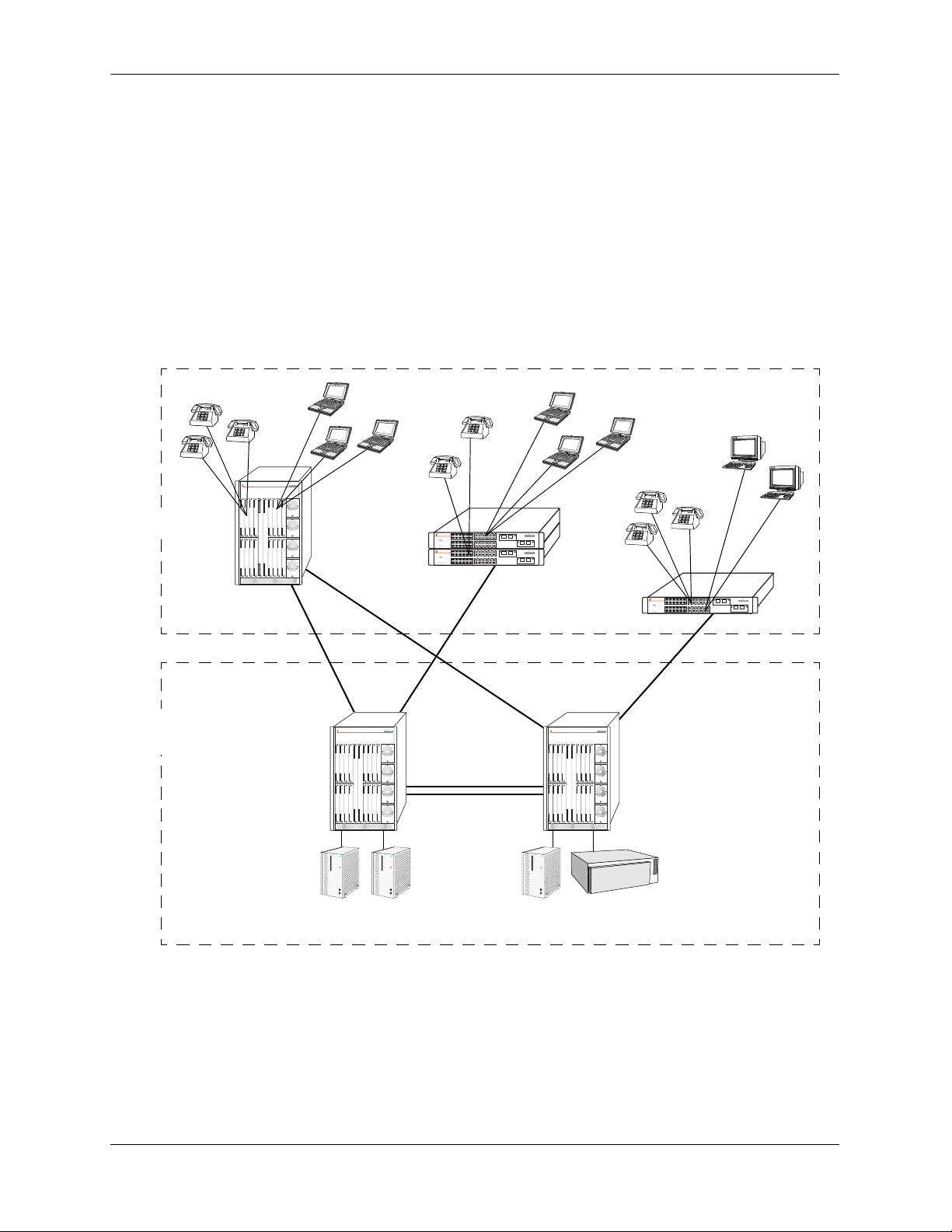
Single Office Building with 1000 Users
The following diagram shows converged voice and data applications, with 1000 users, in a single building
enterprise environment. Edge devices consist of a mixture of PCs and IP telephones. In this example, a
single OmniPCX 4400 in the core supports IP voice initiations and terminations. An OmniSwitch 7800
switch provides a port density of 1000 10/100 ports. The stackable OmniSwitch 6600 Family configurations provide redundant and dual connectivity from the edge to the redundant backbone/core, in which the
OmniSwitch 7800 core switches are used.
Edge
Backbone
Data Center
IP Phones
OmniSwitch 7800
IP Phones
Gigabit Gigabit
OmniSwitch 6648
OmniSwitch 6648
Gigabit
OmniSwitch 7800 OmniSwitch 7800
Gigabit
IP Phones
Gigabit
OmniSwitch 6648
Server Farm Server
OmniPCX
page 1-6 OmniSwitch 6600 Family Hardware Users Guide September 2006
Page 23
OmniSwitch 6600 Family Application Examples
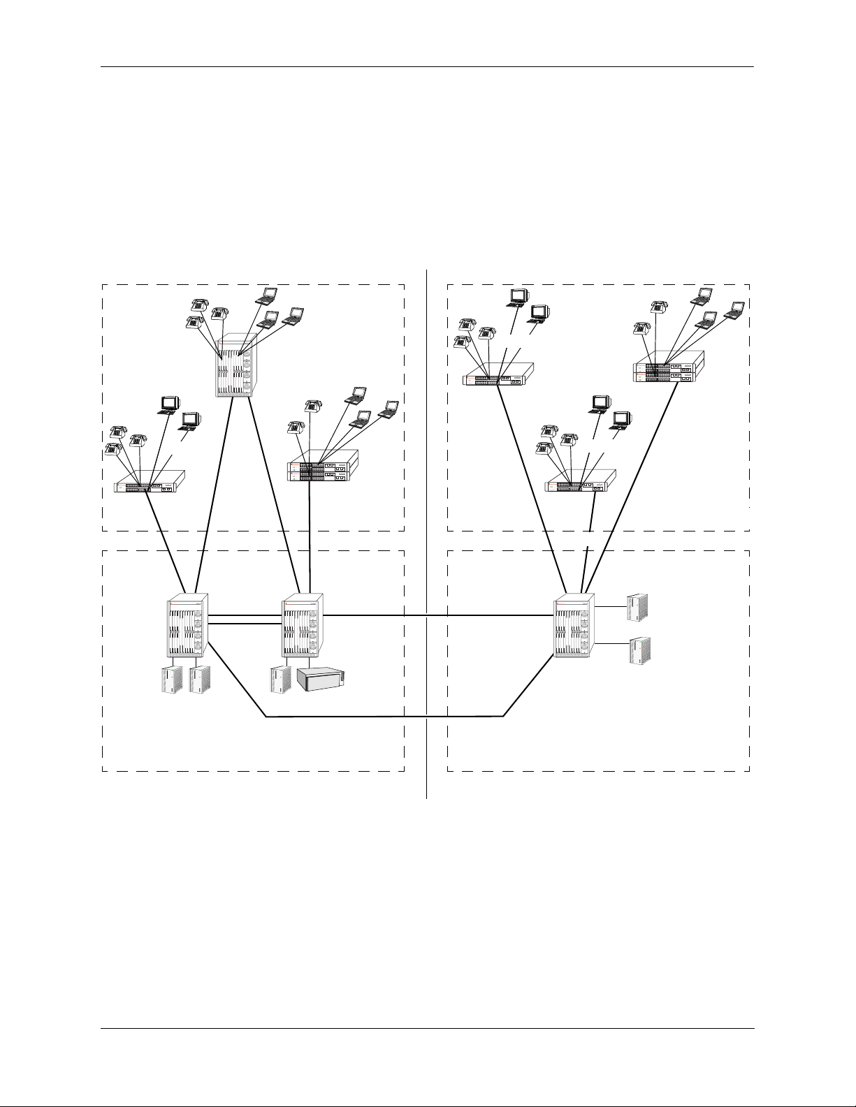
Medium Campus with 1500 Users
This example illustrates converged voice and data applications with 1500 users spread across two buildings in an enterprise campus. Edge devices consist of a mixture of PCs and IP telephones. And, like the
previous example, a single OmniPCX 4400 in the core supports IP voice initiations and terminations.
In building number one, an OmniSwitch 7800 switch provides a port density of 1000 10/100 ports, and the
stackable OmniSwitch 6600 Family configurations provide redundant and dual connectivity from the edge
to the redundant backbone/core. In building number two, the stackable OmniSwitch 6600 Family configurations provide 500 ports for connectivity from the edge to the backbone/core.
IP Phones
IP Phones
OmniSwitch 6648
10/10010/100
OmniSwitch 7800
Server Farm
OmniSwitch 7800
Gigabit
10/100
IP Phones
OmniSwitch 6648
OmniSwitch 6648
OmniSwitch 7800
10/100
Edge
OmniPCX
Backbone
Data Center
OmniSwitch 6648
Gigabit
10/100
OmniSwitch 6648
Gigabit
OmniSwitch 7800
10/100
OmniSwitch 6648
OmniSwitch 6648
Server Farm
Backbone
Data Center
10/100
Edge
Building Number One Building Number Two
OmniSwitch 6600 Family Hardware Users Guide September 2006 page 1-7
Page 24

Application Examples OmniSwitch 6600 Family
page 1-8 OmniSwitch 6600 Family Hardware Users Guide September 2006
Page 25

2 OmniSwitch 6600 Family
Chassis and Hardware
Components
OmniSwitch 6600 Family switches are available in six stackable chassis configurations—the 24-port
OmniSwitch 6624 (OS6624), OmniSwitch 6600-U24 (OS6600-U24), OmniSwitch 6600-P24 (OS6600P24), and OmniSwitch 6602-24 (OS6602-24) and the 48-port OmniSwitch 6648 (OS6648) and
OmniSwitch 6602-48 (OS6602-48). This chapter includes detailed information on each of these chassis
types. Topics include:
• OmniSwitch 6600 Family chassis descriptions
• Technical specifications
• Switch mounting
• Backup power supply
• Gigabit Ethernet uplink and stacking modules
• MiniGBICs
• 100 Mbps SFPs
• Temperature management
• Pinouts and console port specifications
• Monitoring switch status
• Base chassis MAC address
OmniSwitch 6600 Family Hardware Users Guide September 2006 page 2-1
Page 26
OmniSwitch 6600 Family Chassis and Hardware Components OmniSwitch 6624
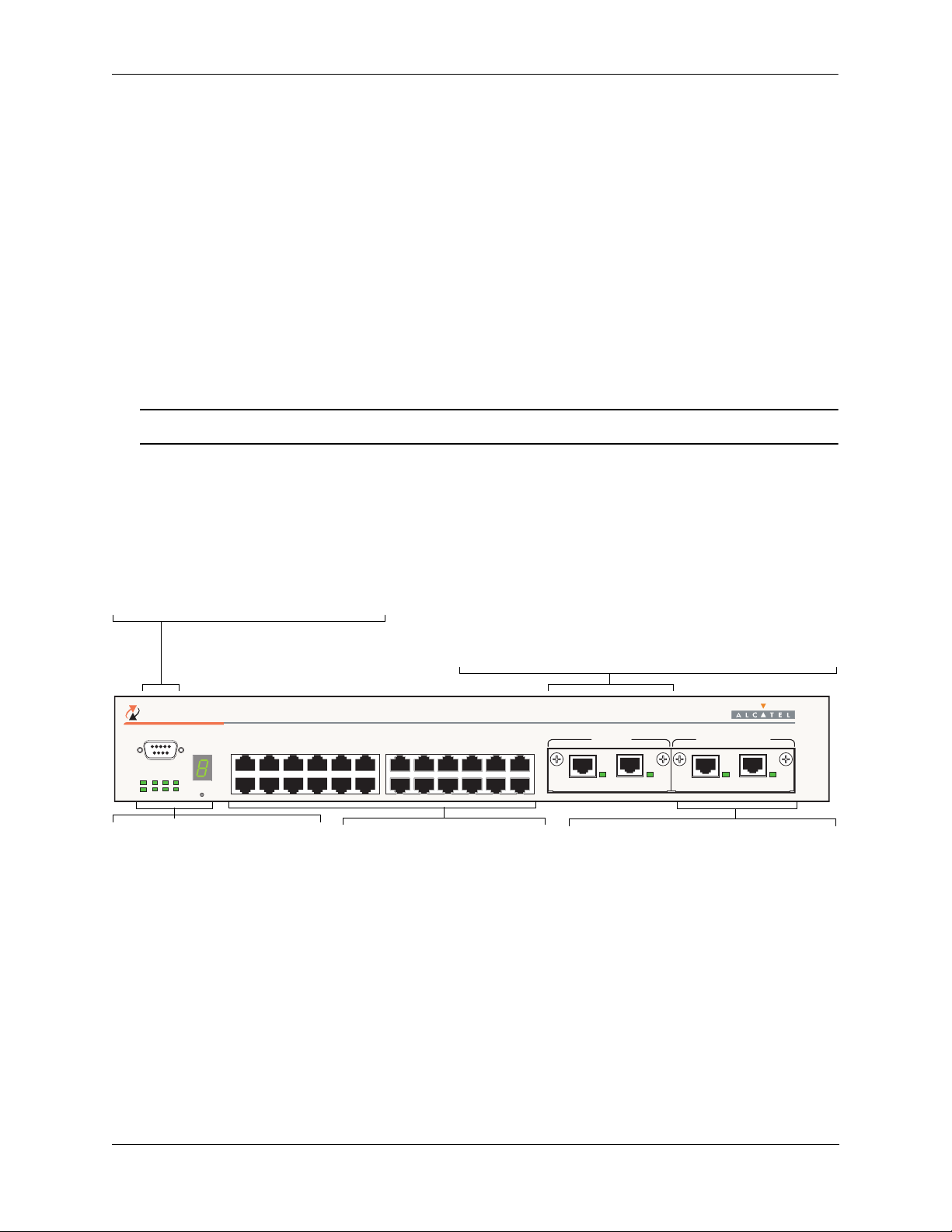
OmniSwitch 6624
The OS6624 is a stackable edge/workgroup switch offering 24 10/100 Ethernet ports. The OS6624 can
also be equipped with upto four Gigabit Ethernet ports for connections to a high speed backbone or server.
The front panel of the OS6624 chassis contains the following major components:
• Console (DB-9) port
• Stack indicator LED
• 24 10/100 Ethernet ports
• One slot for OS6600-GNI-U2 (fiber) or OS6600-GNI-C2 (copper) Gigabit Ethernet uplink module
• One slot for Gigabit Ethernet uplink module as described above or stacking module
Note. The OmniSwitch 6624 is also known as the OmniSwitch 6602-24.
Refer to the illustration below for more front panel information. For detailed LED descriptions, refer to
page 2-18. For information on the chassis rear panel, refer to page 2-20.
Console Port
The OS6624 front panel provides one RS232
port for console connections. Serial console
connections are used by network administrators
for switch management. This female DB-9 connector provides a DCE console connection.
Gigabit Ethernet Uplink Module Slot
The OS6624 provides a dedicated slot for Gigabit Ethernet uplink
modules. This slot supports the following module types:
• OS6600-GNI-C2—Provides two fixed 1000BaseT copper
connections (uses two RJ-45 connectors). Supports distances
up to 100 meters.
• OS6600-GNI-U2—Provides two MiniGBIC bays that
support hot-swappable 1000BASE-X MiniGBIC transceivers.
OmniSwitch 6624
TM
CONSOLE
34567891011
1
OK1
PS1
PRI
TEMP
OK2
PS2
SEC
FAN SEL
2
Status and Slot Indicator LEDs
For information on the OS6624’s
status and slot indicator LEDs,
refer to page 2-18.
Slot Selector Button
The slot selector button, located
directly beneath the slot indicator
LED, is used to manually assign
slot numbers to switches in stacked
configurations. Refer to Chapter 4,
“Managing OmniSwitch 6600
Family Stacks,” for detailed infor-
mation.
1314151617181920212223
12
24
10/100 Ethernet Ports
The OS6624 provides 24 10/100
Ethernet ports. These ports are
twisted-pair and are individually
configurable as 10BaseT or
100BaseTX. The ports use RJ-45
connectors.
25 26 27 28
LINK/ACT
LINK/ACT
Stacking or Uplink Module Slot
The OS6624 provides an additional slot that
can accommodate either a stacking module or
a Gigabit Ethernet uplink module.
If you use a Gigabit Ethernet uplink module
in this slot, the OS6624 must be used as a
stand-alone switch.
A stacking module must be installed in this
slot if the switch is to be used in a stack. For
detailed information on stacking switches,
refer to Chapter 4, “Managing OmniSwitch
6600 Family Stacks.”
EXPANSION/STACKINGEXPANSION
LINK/ACT
LINK/ACT
OmniSwitch 6624 Front Panel
OmniSwitch 6600 Family Hardware Users Guide September 2006 page 2-2
Page 27

OmniSwitch 6600 Family Chassis and Hardware Components OmniSwitch 6624
OS6624 Specifications
Total number of 10/100 Mbps
24
ports per switch
Total number of Gigabit
4 (for stand-alone switches); 2 (for stacked configurations)
Ethernet ports per switch
Total number of 10/100 Mbps
192 (stack of eight switches)
ports per stack
Total number of Gigabit
16 (stack of eight switches)
Ethernet ports per stack
Fabric capacity 7.0 Gbps full duplex; 14 Gbps aggregate
Current draw Approximately 2.3 Amps
Power Approximately 55 Watts
Total available power supplies 2 (one factory-installed power supply and one optional backup power
supply)
Flash memory size 64 MB
RAM memory size 128 MB
Overall Width (rack-mount
19.125 inches
flanges included)
Chassis Width (rack-mount
17.2 inches
flanges not included)
Height 2.65 inches
Height (rack units) 1.5 RU
Chassis Depth 14 inches
Chassis Weight Approximately 12 lbs (13.5 lbs with optional backup power supply
installed)
Humidity 5% to 90% Relative Humidity (Operating)
0% to 95% Relative Humidity (Storage)
Altitude Sea level to 10,000 feet (3 km)
10/100 Ethernet Port Specifications
Connector type RJ-45
Standards supported IEEE 802.3u, IAB RFCs 826, 894
Data rate 10 or 100 Mbps (full or half duplex)
Maximum frame size 1518 Bytes; 1522 Bytes with IEEE 802.1Q tags
Connections supported 10BaseT hub or device; 100BaseTX hub or device
Cable supported 10BaseT: unshielded twisted-pair (UTP)
100BaseTX: unshielded twisted-pair (UTP), Category 5, EIA/TIA 568
or shielded twisted-pair (STP), Category 5, 100 ohm
Maximum cable distance 100 meters
OmniSwitch 6600 Family Hardware Users Guide September 2006 page 2-3
Page 28

OmniSwitch 6600 Family Chassis and Hardware Components OmniSwitch 6600-U24
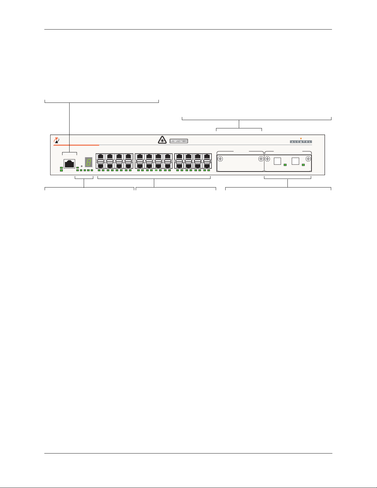
OmniSwitch 6600-U24
The OS6600-U24 is a stackable edge/workgroup switch offering 24 fiber 100 Mbps Ethernet SFP ports.
The OS6600-U24 can also be equipped with up to four Gigabit Ethernet ports for connections to a high
speed backbone or server.
The front panel of the OS6600-U24 chassis contains the following major components:
• Console (RJ-45) port
• Stack indicator LED
• 24 fiber 100 Ethernet SFP ports
• One slot for OS6600-GNI-U2 (fiber) or OS6600-GNI-C2 (copper) Gigabit Ethernet uplink module
• One slot for Gigabit Ethernet uplink module as described above or stacking module
The following SFP transceivers are available for the OS6600-U24:
• SFP-100-LC-MM—100Base FX multimode 62.5/125 and 50/125 micron fiber, supports distances up
to 2 km; uses LC connectors.
• SFP-100-LC-SM15—100Base FX single mode 9/125 micron fiber, supports distances up to 15 km;
uses LC connectors.
• SFP-100-LC-SM40—100Base FX single mode 9/125 micron fiber, supports distances up to 40 km;
uses LC connectors.
• SFP-100-MTRJ-MM—100Base FX multimode 62.5/125 and 50/125 micron fiber, supports distances
up to 2 km; uses MTRJ connectors.
Note. See “Installing SFPs (OS6600-U24)” on page 2-51 for information on installing SFP transceivers.
Refer to the illustration on the following page for more front panel information. For detailed LED descriptions, refer to page 2-18. For information on the chassis rear panel, refer to page 2-20.
OmniSwitch 6600 Family Hardware Users Guide September 2006 page 2-4
Page 29
OmniSwitch 6600 Family Chassis and Hardware Components OmniSwitch 6600-U24
Console Port
The OS6600-U24 front panel provides one RJ-45
port for console connections. Serial console connections are used by network administrators for
switch management. This female RJ-45connector
provides a DCE console connection.
OmniSwitch 6600-U24
TM
357 911
CONSOLE
OK1
OK2
SEL
PS1
PS2 PRI SEC TEMPFAN
Status and Slot Indicator LEDs
For information on the OS6600-U24’s
status and slot indicator LEDs, refer to
page 2-18.
1
2 24
2143658710912111413
100 Fiber Ethernet SFP Ports
The OS6600-U24 provides 24
fiber 100 Ethernet SFP ports.
These ports can use the SFP-100LC-MM, SFP-100-LC-SM, and
Slot Selector Button
The slot selector button, located
SFP-100-MTRJ-MM transceivers
in any combination.
directly beneath the slot indicator
LED, is used to manually assign
slot numbers to switches in stacked
configurations. Refer to Chapter 4,
“Managing OmniSwitch 6600
Family Stacks,” for detailed infor-
mation.
Gigabit Ethernet Uplink Module Slot
The OS6600-U24 provides a dedicated slot for Gigabit Ethernet
uplink modules. This slot supports the following module types:
• OS6600-GNI-C2—Provides two fixed 1000BaseT copper
connections (uses two RJ-45 connectors). Supports distances
up to 100 meters.
• OS6600-GNI-U2—Provides two MiniGBIC bays that
support hot-swappable 1000BASE-X MiniGBIC transceivers.
13 15 17 19 21
1615 1817 2019 2221 2423
23
25 26 27 28
EXPANSION/STACKINGEXPANSION
LINK/ACT
LINK/ACT
Stacking or Uplink Module Slot
The OS6600-U24 provides an additional slot
that can accommodate either a stacking module or a Gigabit Ethernet uplink module.
If you use a Gigabit Ethernet uplink module
in this slot, the OS66600-U24 must be used
as a stand-alone switch.
A stacking module must be installed in this
slot if the switch is to be used in a stack. For
detailed information on stacking switches,
refer to Chapter 4, “Managing OmniSwitch
6600 Family Stacks.”
OmniSwitch 6600-U24 Front Panel
OmniSwitch 6600 Family Hardware Users Guide September 2006 page 2-5
Page 30

OmniSwitch 6600 Family Chassis and Hardware Components OmniSwitch 6600-U24
OS6600-U24 Specifications
Total number of 100 Mbps SFP
24
ports per switch
Total number of Gigabit
4 (for stand-alone switches); 2 (for stacked configurations)
Ethernet ports per switch
Total number of 100 Mbps SFP
192 (stack of eight switches)
ports per stack
Total number of Gigabit
16 (stack of eight switches)
Ethernet ports per stack
Fabric capacity 7.0 Gbps full duplex; 14 Gbps aggregate
Power The OS6600-U24 power supply provides 100 W
Total available power supplies 2 (one factory-installed power supply and one optional backup power
supply)
Flash memory size 64 MB
RAM memory size 128 MB
Overall Width (rack-mount
19.125 inches
flanges included)
Chassis Width (rack-mount
17.2 inches
flanges not included)
Height 2.65 inches
Height (rack units) 1.5 RU
Chassis Depth 14 inches
Chassis Weight Approximately 11.56 lbs not including uplink/stacking modules or
SFPs (13.06 lbs with optional backup power supply installed)
Humidity 5% to 90% Relative Humidity (Operating)
0% to 95% Relative Humidity (Storage)
Altitude Sea level to 10,000 feet (3 km)
OmniSwitch 6600 Family Hardware Users Guide September 2006 page 2-6
Page 31

OmniSwitch 6600 Family Chassis and Hardware Components OmniSwitch 6600-U24
100 Mbps Ethernet SFP Port Specifications
Connector type SFP
Standards supported IEEE 802.3u, IAB RFCs 826, 894 (see data sheet for more information)
Data rate 100 Mbps (full or half duplex)
Maximum frame size 1518 Bytes; 1522 Bytes with IEEE 802.1Q tags
Connections supported 100BaseFX
Cable supported SFP-100-LC-MM: 62.5/125 and 50/125 micron multimode fiber
SFP-100-LC-SM: 9/125 micron single mode
SFP-100-MTRJ-MM: 62.5/125 and 50/125 micron multimode fiber
Optical output power SFP-100-LC-MM: -19 to -14 dBm (62.5/125 micron);
-22.5 to -14 dBm (50/125 micron)
SFP-100-LC-SM15: -15 to -8 dBm
SFP-100-LC-SM40: -5 to 0 dBm
SFP-100-MTRJ-MM: -20 to -14 dBm
Input optical power
(Receiver sensitivity)
SFP-100-LC-MM: -31 to -14 dBm
SFP-100-LC-SM15: -31 to 0dBm
SFP-100-LC-SM40: -34 to 0 dBm
SFP-100-MTRJ-MM: -31 to -14 dBm
Maximum cable distance SFP-100-LC-MM: 2 km
SFP-100-LC-SM15: 15 km
SFP-100-LC-SM40: 40 km
SFP-100-MTRJ-MM: 2 km
OmniSwitch 6600 Family Hardware Users Guide September 2006 page 2-7
Page 32

OmniSwitch 6600 Family Chassis and Hardware Components OmniSwitch 6600-P24
OmniSwitch 6600-P24
The OS6600-P24 is a stackable edge/workgroup switch offering 24 Power over Ethernet (PoE) 10/100
Ethernet ports. The OS6600-P24 can also be equipped with up to four Gigabit Ethernet ports for connections to a high speed backbone or server.
The front panel of the OS6600-P24 chassis contains the following major components:
• Console (RJ-45) port
• Stack indicator LED
• 24 10/100 PoE ports
• One slot for OS6600-GNI-U2 (fiber) or OS6600-GNI-C2 (copper) Gigabit Ethernet uplink module
• One slot for Gigabit Ethernet uplink module as described above or stacking module
OmniSwitch 6600 Family Hardware Users Guide September 2006 page 2-8
Page 33

OmniSwitch 6600 Family Chassis and Hardware Components OmniSwitch 6600-P24
Refer to the illustration below for more front panel information. For detailed LED descriptions, refer to
page 2-18. For information on the chassis rear panel, refer to page 2-20.
Console Port
The OS6600-P24 front panel provides one RJ45 port for console connections. Serial console
connections are used by network administrators
for switch management. This female RJ-45 connector provides a DCE console connection.
OmniSwitch 6600-P24
TM
34567891011
CONSOLE
OK1
PS1
OK2
PS2
SEC
PRI
Status and Slot Indicator LEDs
For information on the OS6600-P24’s
status and slot indicator LEDs, refer
to page 2-18.
1
SEL
TEMP
FAN
2
12
10/100 Ethernet Ports
The OS6600-P24 provides 24
Power over Ethernet (PoE) 10/100
Ethernet ports. These ports are
twisted-pair and are individually
Slot Selector Button
The slot selector button, located
directly beneath the slot indicator
LED, is used to manually assign
configurable as 10BaseT or
100BaseTX. The ports use RJ-45
connectors. For information more
information, refer to page 2-18.
slot numbers to switches in stacked
configurations.
Gigabit Ethernet Uplink Module Slot
The OS6600-P24 provides a dedicated slot for Gigabit Ethernet
uplink modules. This slot supports the following module types:
• OS6600-GNI-C2—Provides two fixed 1000BaseT copper
connections (uses two RJ-45 connectors). Supports distances
up to 100 meters.
• OS6600-GNI-U2—Provides two MiniGBIC bays that
support hot-swappable 1000BASE-X MiniGBIC transceivers.
1314151617181920212223
25 26 27 28
LINK/ACT
LINK/ACT
24
EXPANSION/STACKINGEXPANSION
LINK/ACT
LINK/ACT
Stacking or Uplink Module Slot
The OS6600-P24 provides an additional slot
that can accommodate either a stacking module or a Gigabit Ethernet uplink module.
If you use a Gigabit Ethernet uplink module
in this slot, the OS6600-P24 must be used as
a stand-alone switch.
A stacking module must be installed in this
slot if the switch is to be used in a stack. For
detailed information on stacking switches,
refer to Chapter 4, “Managing OmniSwitch
6600 Family Stacks.”
OmniSwitch 6600-P24 Front Panel
OmniSwitch 6600 Family Hardware Users Guide September 2006 page 2-9
Page 34

OmniSwitch 6600 Family Chassis and Hardware Components OmniSwitch 6600-P24
OS6600-P24 Specifications
Total number of PoE 10/100
24
Mbps ports per switch
Total number of Gigabit
4 (for stand-alone switches); 2 (for stacked configurations)
Ethernet ports per switch
Total number of PoE 10/100
192 (stack of eight switches)
Mbps ports per stack
Total number of Gigabit
16 (stack of eight switches)
Ethernet ports per stack
Fabric capacity 7.0 Gbps full duplex; 14 Gbps aggregate
Current draw Switch functions (24 Volts max.): 2.3 Amps
PoE (49 Volts max.): 4.3 Amps
Power Switch functions (24 Volts max.): 55 Watts (100 Watts available)
PoE (49 Volts max.): 210 Watts
Total available power supplies
(OS6600-P24)
Total available power supplies
(OS6600-BPS-P)
2: Two built-in factory-installed power supplies (one powering switch
functions and the other powering PoE)
2: Two built-in factory-installed power supplies (one powering switch
functions and the other powering PoE)
Flash memory size 64 MB
RAM memory size 128 MB
Overall Width (rack-mount
19.025 inches
flanges included)
Chassis Width (rack-mount
17.1 inches
flanges not included)
Height 2.65 inches
Height (rack units) 1.5 RU
Chassis Depth 14.5 inches (without an OS6600-BPS-P)
19.3 inches (with an OS6600-BPS-P)
Chassis Weight Approximately 12 lbs
Humidity 5% to 90% Relative Humidity (Operating)
0% to 95% Relative Humidity (Storage)
Altitude Sea level to 10,000 feet (3 km)
OmniSwitch 6600 Family Hardware Users Guide September 2006 page 2-10
Page 35

OmniSwitch 6600 Family Chassis and Hardware Components OmniSwitch 6600-P24
10/100 Power over Ethernet (PoE) Port Specifications
Connector type RJ-45
Standards supported IEEE 802.3u, 802.3af (DTE Power via MDI MIB); IAB RFCs 826, 894
Data rate 10 or 100 Mbps (full or half duplex)
Maximum frame size 1518 Bytes; 1522 Bytes with IEEE 802.1Q tags
Connections supported 10BaseT or 100BaseTX IP phones, Bluetooth Access Points, Internet
cameras, and other devices requiring power over Ethernet
Cable supported 10BaseT: unshielded twisted-pair (UTP)
100BaseTX: unshielded twisted-pair (UTP), Category 5, EIA/TIA 568
or shielded twisted-pair (STP), Category 5, 100 ohm
Power supplied to port 15.4 watts per port
Maximum cable distance 100 meters
OmniSwitch 6600 Family Hardware Users Guide September 2006 page 2-11
Page 36

OmniSwitch 6600 Family Chassis and Hardware Components OmniSwitch 6648
OmniSwitch 6648
The OS6648 is a stackable edge/workgroup switch offering 48 10/100 Ethernet ports. The OS6648 can
also be equipped with up to four Gigabit Ethernet ports for connections to a high speed backbone or
server.
The front panel of the OS6648 chassis contains the following major components:
• Console (DB-9) port
• Stack indicator LED
• 48 10/100 Ethernet ports
• One slot for OS6600-GNI-U2 (fiber) or OS6600-GNI-C2 (copper) Gigabit Ethernet uplink module
• One slot for Gigabit Ethernet uplink module as described above or stacking module
Note. The OmniSwitch 6648 is also known as the OmniSwitch 6600-48.
Refer to the illustration below for more front panel information. For detailed LED descriptions, refer to
page 2-18. For information on the chassis rear panel, refer to page 2-20.
Console Port
The OS6648 front panel provides one RS232
port for console connections. Serial console
connections are used by network administrators
for switch management. This female DB-9 connector provides a DCE console connection.
272829303132333435
OmniSwitch 6648
TM
CONSOLE
OK1
PS1
PRI
TEMP
OK2
PS2
SEC
FAN
Status and Slot Indicator LEDs
For information on the OS6648’s
status and slot indicator LEDs,
refer to page 2-18.
Slot Selector Button
The slot selector button, located
directly beneath the slot indicator
25
26
34567891011
1
SEL
2
36
12
10/100 Ethernet Ports
The OS6648 provides 48 10/100
Ethernet ports. These ports are
twisted-pair and are individually
configurable as 10BaseT or
100BaseTX. The ports use RJ-45
connectors.
LED, is used to manually assign
slot numbers to switches in stacked
configurations. Refer to Chapter 4,
“Managing OmniSwitch 6600
Family Stacks,” for detailed infor-
mation.
OmniSwitch 6648 Front Panel
Gigabit Ethernet Uplink Module Slot
The OS6648 provides a dedicated slot for Gigabit Ethernet uplink
modules. This slot supports the following module types:
• OS6600-GNI-C2—Provides two fixed 1000BaseT copper
connections (uses two RJ-45 connectors). Supports distances
up to 100 meters.
• OS6600-GNI-U2—Provides two MiniGBIC bays that
support hot-swappable 1000BASE-X MiniGBIC transceivers.
3738394041424344454647
1314151617181920212223
EXPANSION
LINK/ACT
EXPANSION/STACKING
LINK/ACT
LINK/ACT
LINK/ACT
48
24
49 50 51 52
Stacking or Uplink Module Slot
The OS6648 provides an additional slot that
can accommodate either a stacking module or
a Gigabit Ethernet uplink module.
If you use a Gigabit Ethernet uplink module
in this slot, the OS6648 must be used as a
stand-alone switch.
A stacking module must be installed in this
slot if the switch is to be used in a stack. For
detailed information on stacking switches,
refer to Chapter 4, “Managing OmniSwitch
6600 Family Stacks.”
OmniSwitch 6600 Family Hardware Users Guide September 2006 page 2-12
Page 37

OmniSwitch 6600 Family Chassis and Hardware Components OmniSwitch 6648
OS6648 Specifications
Total number of 10/100 Mbps
48
ports per switch
Total number of Gigabit Ether-
net ports per switch
Total number of 10/100 Mbps
4 (for stand-alone switches);
2 (for stacked configurations)
384 (stack of eight switches)
ports per stack
Total number of Gigabit Ether-
16 (stack of eight switches)
net ports per stack
Fabric capacity 10.0 Gbps full duplex; 20.0 Gbps aggregate
Current draw Approximately 2.3 Amps
Power Approximately 55 Watts
Total power supplies 2 (one factory-installed power supply and
one optional backup power supply)
Flash memory size 64 MB
RAM memory size 128 MB
Overall Width (rack-mount
19.125 inches
flanges included)
Chassis Width (rack-mount
17.2 inches
flanges not included)
Height 2.65 inches
Height (rack units) 1.5 RU
Chassis Depth 14 inches
Chassis Weight Approximately 14 lbs (15.5 lbs with optional
backup power supply installed)
Humidity 5% to 90% Relative Humidity (Operating)
0% to 95% Relative Humidity (Storage)
Altitude Sea level to 10,000 feet (3 km)
10/100 Ethernet Port Specifications
Connector type RJ-45
Standards supported IEEE 802.3u, IAB RFCs 826, 894
Data rate 10 or 100 Mbps (full or half duplex)
Maximum frame size 1518 Bytes; 1522 Bytes with IEEE 802.1Q tags
Connections supported 10BaseT hub or device; 100BaseTX hub or device
Cable supported 10BaseT: unshielded twisted-pair (UTP)
100BaseTX: unshielded twisted-pair (UTP), Category 5, EIA/TIA 568
or shielded twisted-pair (STP), Category 5, 100 ohm
Maximum cable distance 100 meters
OmniSwitch 6600 Family Hardware Users Guide September 2006 page 2-13
Page 38

OmniSwitch 6600 Family Chassis and Hardware Components OmniSwitch 6602-24
35698
10
1
1
1
20
2
SEC
28
CLASS
UCT
252
S
C
1
S2
Sel
OK2
OmniSwitch 6602-24
The OS6602-24 is a stackable edge/workgroup switch offering 24 10/100 Ethernet ports. The OS6602-24
has Gigabit Ethernet ports for connections to a high speed backbone or server and two ports for stacking
switches.
The front panel of the OS6602-24 chassis contains the following major components:
• Console (RJ-45) port
• Stack indicator LED
• 24 10/100 Ethernet ports
• Two MiniGBIC Gigabit Ethernet uplink ports
• Two stacking ports
Refer to the illustration below for more front panel information. For detailed LED descriptions, refer to
page 2-18. For information on the chassis rear panel, refer to page 2-20.
10/100 Ethernet Ports
The OS6602-24 provides 24 10/100
Ethernet ports. These ports are
twisted-pair and are individually
configurable as 10BaseT or
100BaseTX. The ports use RJ-45
connectors.
Console Port
The OS6602-24 front panel provides one serial port for console
connections. Serial console connections are used by network
administrators for switch management. This female RJ-45 connector provides a DCE console
connection.
Status and Slot Indicator LEDs
For information on the OS6602-24’s
status and slot indicator LEDs, refer
to page 2-18.
Slot Selector Button
The slot selector button, located to
the right of the slot indicator LED,
is used to manually assign slot
numbers to switches in stacked
configurations. Refer to Chapter 4,
“Managing OmniSwitch 6600
Family Stacks,” for detailed infor-
mation.
3
7161514 211918
Gigabit Ethernet Uplink Ports
The OS6602-24 provides two MiniGBIC
Gigabit Ethernet slots. Refer to page 2-45 for
information on MiniGBIC types.
2 2324
Stacking Ports
The OS6602-24 provides two built-in stacking
ports. Refer to Chapter 4, “Managing
OmniSwitch 6600 Family Stacks,” for detailed
OmniSwitch 6602-24
TM
o
n
s
o
l
1 LASER PROD
PS1OK
P
6
27
tack
information on using these ports to stack switches
in a stack.
OmniSwitch 6602-24 Front Panel
OmniSwitch 6600 Family Hardware Users Guide September 2006 page 2-14
Page 39

OmniSwitch 6600 Family Chassis and Hardware Components OmniSwitch 6602-24
OS6602-24 Specifications
Total number of 10/100 Mbps
24
ports per switch
Total number of Gigabit
2
Ethernet ports per switch
Total number of 10/100 Mbps
192 (stack of eight switches)
ports per stack
Total number of Gigabit
16 (stack of eight switches)
Ethernet ports per stack
Fabric capacity 7.0 Gbps full duplex; 14 Gbps aggregate
Current draw Approximately 0.3 Amps @ 115VAC
Power Approximately 34 Watts @ 25C
Total available power supplies 2 (one factory-installed power supply and one optional backup power
supply)
Flash memory size 64 MB
RAM memory size 128 MB
Overall Width (rack-mount
18.95 inches
flanges included)
Chassis Width (rack-mount
17.25 inches
flanges not included)
Height 1.75 inches
Height (rack units) 1 RU
Chassis Depth 16.95 inches
Chassis Weight Approximately 11.9 lbs
Humidity 5% to 90% Relative Humidity (Operating)
0% to 95% Relative Humidity (Storage)
Altitude Sea level to 10,000 feet (3 km)
10/100 Ethernet Port Specifications
Connector type RJ-45
Standards supported IEEE 802.3u, IAB RFCs 826, 894
Data rate 10 or 100 Mbps (full or half duplex)
Maximum frame size 1518 Bytes; 1522 Bytes with IEEE 802.1Q tags
Connections supported 10BaseT hub or device; 100BaseTX hub or device
Cable supported 10BaseT: unshielded twisted-pair (UTP)
100BaseTX: unshielded twisted-pair (UTP), Category 5, EIA/TIA 568
or shielded twisted-pair (STP), Category 5, 100 ohm
Maximum cable distance 100 meters
OmniSwitch 6600 Family Hardware Users Guide September 2006 page 2-15
Page 40

OmniSwitch 6600 Family Chassis and Hardware Components OmniSwitch 6602-48
3
1
5
6
9810
1311615191820
23
4
SEC
PR1
52
CLASS
9
50
S
k
1
PS1
O
PS
S
OK2
FAN
62829
303
36
353
4
8454
42
44464
48
2
OmniSwitch 6602-48
The OS6602-48 is a stackable edge/workgroup switch offering 48 10/100 Ethernet ports. The OS6602-48
has Gigabit Ethernet ports for connections to a high speed backbone or server and two ports for stacking
switches.
The front panel of the OS6602-48 chassis contains the following major components:
• Console (RJ-45) port
• Stack indicator LED
• 48 10/100 Ethernet ports
• Two MiniGBIC Gigabit Ethernet uplink ports
• Two stacking ports
Refer to the illustration below for more front panel information. For detailed LED descriptions, refer to
page 2-18. For information on the chassis rear panel, refer to page 2-20.
10/100 Ethernet Ports
The OS6602-48 provides 48 10/100
Ethernet ports. These ports are
twisted-pair and are individually
configurable as 10BaseT or
100BaseTX. The ports use RJ-45
connectors.
Console Port
The OS6602-48 front panel provides one serial port for console
connections. Serial console connections are used by network
administrators for switch management. This female RJ-45 connector provides a DCE console
connection.
Status and Slot Indicator LEDs
For information on the OS6602-48’s
status and slot indicator LEDs, refer
to page 2-18.
Slot Selector Button
The slot selector button, located to
the right of the slot indicator LED,
is used to manually assign slot
numbers to switches in stacked
configurations. Refer to Chapter 4,
“Managing OmniSwitch 6600
Family Stacks,” for detailed infor-
mation.
2
Gigabit Ethernet Uplink Ports
The OS6602-48 provides two MiniGBIC
Gigabit Ethernet slots. Refer to page 2-45 for
information on MiniGBIC types.
2
5
1 3332 34
7
140393
3
7
OmniSwitch 6602-48
TM
C
o
el
4
n
s
o
1 LASER PRODUCT
K1
l
TMP
2
5
tac
Stacking Ports
The OS6602-48 provides two built-in stacking
ports. Refer to Chapter 4, “Managing
OmniSwitch 6600 Family Stacks,” for detailed
information on using these ports to stack switches
in a stack.
OmniSwitch 6602-48 Front Panel
OmniSwitch 6600 Family Hardware Users Guide September 2006 page 2-16
Page 41

OmniSwitch 6600 Family Chassis and Hardware Components OmniSwitch 6602-48
OS6602-48 Specifications
Total number of 10/100 Mbps
48
ports per switch
Total number of Gigabit Ether-
2
net ports per switch
Total number of 10/100 Mbps
384 (stack of eight switches)
ports per stack
Total number of Gigabit Ether-
16 (stack of eight switches)
net ports per stack
Fabric capacity 10.0 Gbps full duplex; 20.0 Gbps aggregate
Current draw Approximately 0.4 Amps @ 115VAC
Power Approximately 46 Watts @ 25C
Total power supplies 2 (one factory-installed power supply and
one optional backup power supply)
Flash memory size 64 MB
RAM memory size 128 MB
Overall Width (rack-mount
18.95 inches
flanges included)
Chassis Width (rack-mount
17.25 inches
flanges not included)
Height 1.75 inches
Height (rack units) 1 RU
Chassis Depth 16.95 inches
Chassis Weight Approximately 12.0 lbs
Humidity 5% to 90% Relative Humidity (Operating)
0% to 95% Relative Humidity (Storage)
Altitude Sea level to 10,000 feet (3 km)
10/100 Ethernet Port Specifications
Connector type RJ-45
Standards supported IEEE 802.3u, IAB RFCs 826, 894
Data rate 10 or 100 Mbps (full or half duplex)
Maximum frame size 1518 Bytes; 1522 Bytes with IEEE 802.1Q tags
Connections supported 10BaseT hub or device; 100BaseTX hub or device
Cable supported 10BaseT: unshielded twisted-pair (UTP)
100BaseTX: unshielded twisted-pair (UTP), Category 5, EIA/TIA 568
or shielded twisted-pair (STP), Category 5, 100 ohm
Maximum cable distance 100 meters
OmniSwitch 6600 Family Hardware Users Guide September 2006 page 2-17
Page 42

OmniSwitch 6600 Family Chassis and Hardware Components Status LEDs
Status LEDs
LEDs provide visual status information. These “status lights” are used to indicate conditions such as
hardware and software status, primary and backup power supply status, primary and secondary status
(stacked configurations), temperature and fan errors, slot number information, link integrity, and data
flow. Refer to the diagram below for detailed information on OmniSwitch 6600 Family LED states.
Ethernet Port LEDs
Each Ethernet port has a built-in corresponding status LED
on the lefthand side (OS6624, OS6648, OS6600-P24),
below the port OS6600-U24), or above the port (OS660224 and OS6602-48). This LED indicates the link and activity status for each Ethernet port. The LED displays green
when a valid Ethernet cable connection exists. Flashes
Slot Indicator LED
The slot indicator LED is manually configurable
and displays the switch’s current slot number in a
stacked configuration (i.e., 1 – 8). For detailed
information on manually setting the switch’s slot
number, refer to Chapter 4, “Managing
OmniSwitch 6600 Family Stacks.”
green as data is transmitted or received on the port.
The OS6600-P24 only has a right-hand PoE LED. This
LED displays solid green when power is properly supplied
to the port. Flashes green when there is an overload or short.
And this LED is off if there is a power failure.
OmniSwitch 6648
TM
CONSOLE
OK1
PS1
PRI
TEMP
OK2
PS2
SEC
FAN
Hardware and Software
Status LEDs
OK1. Hardware Status. Dis-
plays solid green when powered on and the switch has
passed hardware diagnostic
tests. Displays solid amber
when powered on and the
switch has failed hardware
diagnostic tests.
OK2. Software Status. Blinks
green when the switch’s system management software is
operational. Displays solid
amber when a system software failure occurs. Blinks
amber when the software is in
a transitional state (e.g., when
software is being downloaded
to the switch).
Status LED Location
272829303132333435
25
26
34567891011
1
SEL
2
3738394041424344454647
36
1314151617181920212223
12
Power Supply LEDs
PS1. Displays solid green
when the primary (i.e., factoryinstalled) power supply status
is OK and the power supply is
operating normally. Displays
solid amber in the unlikely
event of a power supply failure.
PS2. Displays solid green
when the optional redundant
power supply status is OK and
the power supply is operating
normally. Displays solid amber
if no redundant power supply
is installed or in the unlikely
event of a redundant power
supply failure.
547
LINK/ACT
LINK/ACT
48
24
49 50 51 52
EXPANSION
Stack LEDs
PRI. Displays solid green
when if the switch is either a
stand-alone switch or the primary switch in a stack; otherwise, if the switch status is
secondary or idle, this LED is
off.
SEC. Displays solid green if
the switch is the secondary
switch in a stack; otherwise,
this LED is off.
Port Power LED
(OS6600-P24
only)
EXPANSION/STACKING
LINK/ACT
LINK/ACT
Temperature Management
LEDs
TEMP. Displays solid green
when the switch is operating
within the allowed temperature
range; displays solid amber if a
temperature error occurs (i.e.,
the switch is operating outside
the temperature range).
FAN. Displays solid green
when all fans in the fan tray
are running at normal speed.
Displays solid amber if a fan
error occurs (i.e., one or more
fans are not running at normal
speed).
Front Panel LED Descriptions (OS6648 Shown)
OmniSwitch 6600 Family Hardware Users Guide September 2006 page 2-18
Page 43

OmniSwitch 6600 Family Chassis and Hardware Components Status LEDs
Note. For information on uplink module LEDs, refer to page 2-36. For information on stacking module
LEDs, refer to page 2-39.
OmniSwitch 6600 Family Hardware Users Guide September 2006 page 2-19
Page 44

OmniSwitch 6600 Family Chassis and Hardware Components Rear Panel
Rear Panel
The rear panel of OmniSwitch 6600 Family switches contains the following major components:
Note. Arrangement and location of components vary depending on chassis type.
• Factory-installed power supply (all OmniSwitch 6600 Family switches)
• Backup power supply bay for optional OS6600-BPS (OS6624, OS6648, OS6600-U24), OS6602-BPS
(OS6602-24 and OS6602-48), or OS6602-BPS-DC (OS6602-24 and OS6602-48) power supply
• Connector for OS6600-BPS-P PoE backup power supply (OS6600-P24 only)
• Power switch (OS6624, OS6648, OS6600-U24, OS6600-P24)
• Grounding block for type LCD8-10A-L grounding lug (all OmniSwitch 6600 Family switches)
Power Switch
indicates on position;
indicates off position.
Product, Safety, and Compliance Information
Refer to the “Regulatory Compliance and Safety
Information” chapter for detailed information.
MODEL NO: OS-6648
RATING: 100-240V 50-60Hz, 1.02A
THIS DEVICE COMPLIES WITH PART 15 OF THE FCC RULES. OPERATION
IS SUBJECT TO THE FOLLOWING TWO CONDITIONS:
(1) THIS DEVICE MAY NOT CAUSE HARMFUL INTERFERENCE, AND
(2) THIS DEVICE MUST ACCEPT ANY INTERFERENCE RECEIVED, INCLUDING
INTERFERENCE THAT MAY CAUSE UNDESIRED OPERATION.
THIS CLASS A DIGITAL APPARATUS MEETS ALL REQUIREMENTS OF THE
CANADIAN INTERFERENCE-CAUSING EQUIPMENT REGULATIONS.
CET APPAREIL NUMÉRIQUE DE LA CLASSE A RESPECTE TOUTS LES
EXIGENCES DU REGLEMENT SUR LE MATÉRIEL BROUILLEUR DU CANADA.
Redundant Power Supply Bay
Slot for optional user-installable OS6600-BPS (OS6624,
OS6648, OS6600-U24) or OS6602-BPS (OS6602-24 and
OS6602-48) backup power supply. For more information on
the backup power supply, including technical specifications
and installation instructions, refer to “Backup Power Supply”
on page 2-26.
Note: The OS6600-P24 does not have a backup power supply
bay. Instead, it has a connector for the OS6600-BPS-P PoE
backup power supply.
!
Assembled in the US of US and Non-US Components
CAUTION:
THIS UNIT MAY BE EQUIPPED
WITH TWO POWER CONNECTIONS. TO REDUCE
THE RISK OF ELECTRICAL SHOCK, DISCONNECT
BOTH POWER CONNECTIONS BEFORE
SERVICING UNIT.
U.S. PATENT NO. 5,394,402
LISTED
I.T.E.
5Z71
E164613C
TUV
Rheinland
ProductSafety
ATTENTION:
PLUS D'UN CORDON D'ALIMENTATION. AFIN DE
PREVENIR LES CHOCS ELECTRIQUES, DEBRANCHE
LES DEUX CORDONS D'ALIMENTATION AVANTE DE
FAIRE LA REPARATION.
RR
geprufte
Sicherheit
Power Connector Socket
Type IEC-320-C13. Supports
one 10 amp power cord.
It is recommended that you use
only Alcatel-provided power
cords.
Ground Lug Connection
Unpainted area for Type
LCD copper lug attachment. Refer to page 2-25
for more information.
CET APPAREIL COMPORTE
100/115/230 V
50/60 Hz, 2/2/1 A
LAN PWR PORT
PoE Power Connector
Reserved for use with the
PoE backup power supply
on the OS6600-P24. See
Chapter 3, “Installing and
Managing Power over
Ethernet (PoE).”
OmniSwitch 6600 Family Rear Panel
OmniSwitch 6600 Family Hardware Users Guide September 2006 page 2-20
Page 45

OmniSwitch 6600 Family Chassis and Hardware Components Mounting the Switch
Mounting the Switch
Note. If you are relocating the switch, be sure to power it down and remove all network, stacking, and
power cables before moving.
Airflow Considerations
Be sure that your switch is placed in a well-ventilated, static-free environment. Always allow adequate
clearance at the front, rear, and sides of the switch.
The following diagram shows recommended minimum clearances for adequate chassis airflow and access
to components at the rear of the chassis—e.g., backup power supply and power switch(es).
Rear Recommended 5 inches
minimum at rear of chassis for
access to power switch(es) and
power cord(s).
}
Sides 2 inches minimum at left
and right sides for adequate airflow. For detailed information on
chassis airflow, refer to page 2-58.
Front Recommended 6 inches
minimum at front of chassis for
access to LEDs and network
}
cables.
OmniSwitch 6600 Family Chassis Top View
Note. Never obstruct the air intake vents located at the sides of the chassis. Obstructing these vents can
cause switch failure. Clearance is not required at the top and bottom of the chassis. For detailed chassis
airflow diagrams, refer to “Chassis Airflow” on page 2-58.
OmniSwitch 6600 Family Hardware Users Guide September 2006 page 2-21
Page 46

OmniSwitch 6600 Family Chassis and Hardware Components Mounting the Switch
Installation Options
There are two ways in which the OmniSwitch 6600 Family switches can be installed:
• Tabletop installation
• Rack-mount installation
Installing the Switch on a Tabletop or Bench
OmniSwitch 6600 Family switches can be installed freestanding as tabletop units. Place your switch in a
stable, flat, static-free surface.
Note. OmniSwitch 6600 Family switches must be placed “right side up.” Never attempt to operate a
switch positioned on its side.
To install the switch as a tabletop unit, follow the steps below:
1 Position the chassis on the table or bench where it is to be installed.
2 Be sure that adequate clearance has been provided for chassis airflow and access to the front, back, and
sides of the switch. For recommended clearances, refer to page 2-21. Also, be sure that you have placed
the chassis within reach of all required AC power sources.
3 If you are placing multiple switches in a stacked configuration, carefully stack the remaining switches,
one on top of the other. Up to eight switches may be stacked to form a single virtual chassis. Be sure to
maintain adequate clearance at the front, rear, left, and right side of all switches. Also, be sure that you
have placed all switches in the stack within reach of required AC power sources.
Rack-Mounting the Switch
Refer to the important guidelines below before installing the OmniSwitch chassis in a rack.
• It is recommended that two people install the switch in the rack—one person to hold the chassis and
position it in the rack, and a second person to secure the chassis to the rack using attachment screws
(not supplied).
• Alcatel provides two rack-mount flanges with each OmniSwitch 6600 Family switch. These flanges
support standard 19-inch rack mount installations. These flanges must be attached to the chassis before
the switch can be rack mounted.
Note. If you are installing the switch in a 23-inch wide rack, Alcatel offers optional 23-inch rack-mounting hardware. For more information, contact your Alcatel representative.
• Alcatel does not provide rack-mount screws. Use the screws supplied by the rack vendor.
• To prevent a rack from becoming top heavy, it is recommended that you install heavier equipment at
the bottom of the rack whenever possible.
• If you are installing the switch in a relay rack, be sure to install and secure the rack per the rack manu-
facturer’s specifications.
• Review page 2-21 for important chassis airflow and access recommendations before installing.
OmniSwitch 6600 Family Hardware Users Guide September 2006 page 2-22
Page 47

OmniSwitch 6600 Family Chassis and Hardware Components Mounting the Switch
3
4
8
To rack-mount the switch, follow the steps below:
1 Align the holes in the provided rack-mount flanges with the four threaded holes in the OmniSwitch
chassis. These threaded holes are located in the left and right sides of the chassis, near the front panel.
2 Attach the flanges to the chassis using the provided Phillips-head screws. Be sure to tighten each of the
screws firmly using a Phillips screwdriver.
4
OmniSwitch 662
M
T
LE
ONSO
C
P
TEM
SEL
I
PR
PS1
1
FAN
OK
SEC
S2
P
2
OK
Attaching a Rack-Mount Flange
3 After the rack-mount flanges are secured to the chassis, mark the holes on the rack where the switch is
to be installed.
4 Lift and position the switch until the rack-mount flanges are flush with the rack post.
5 Align the holes in the flanges with the rack holes that were marked in step 3.
6 Once the holes are aligned, insert a rack mount screw (not provided) through the bottom hole of each
flange. Tighten both screws until they are secure.
ACKING
52
EXPANSION/ST
51
4
9
50
EXPANSION
7
Attaching the Switch to the Rack
Note. Be sure to install the screws in the bottom hole of each flange, as shown, before proceeding.
OmniSwitch 6600 Family Hardware Users Guide September 2006 page 2-23
Page 48

OmniSwitch 6600 Family Chassis and Hardware Components Mounting the Switch
7 Once the screws at the bottom of each flange are secure, install the remaining two rack mount screws.
Be sure that all screws are securely tightened.
Note. If you are installing multiple switches in a rack to form a stacked configuration, refer to the “Rack
Mounting Stacked Configurations” section below.
Rack Mounting Stacked Configurations
If you are rack mounting multiple switches in a stacked configuration, be sure to place all switches in
vertically-adjacent rack positions. This will ensure that all required stacking cables will have adequate
length for the installation. For additional instructions on rack mounting a stacked configuration, follow the
steps below:
1 Install the rack mount flanges for all switches that are to be included in the stacked configuration, as
described on page 2-23. Up to eight switches may be stacked to form a single virtual chassis.
2 Place the next switch in the stack directly on top of the previously installed switch.
3 Align the holes in the flanges with the holes in the rack’s vertical posts.
4 Once the holes are aligned, insert a rack mount screw through the bottom hole of each flange. Tighten
both screws until they are secure. Once the screws at the bottom of each flange are secure, install the
remaining two rack mount screws. Be sure that all screws are securely tightened.
5 Repeat steps 1 through 4 above for all remaining switches.
OmniSwitch 6600 Family Hardware Users Guide September 2006 page 2-24
Page 49

OmniSwitch 6600 Family Chassis and Hardware Components Power Cords
Power Cords
Since the power cord is the power supply’s main disconnect device, it should be plugged into an easily
accessible outlet. In the event that your power cord is lost or damaged, refer to the specifications below.
Specifications
The power cord to be used with 115-Volt configuration is a minimum type SJT (SVT) 18/3, rated at 250
Volts AC, 10 Amps with a maximum length of 15 feet. One end terminates in an IEC 320 attachment plug
and the other end terminates in a NEMA 5-15P plug.
The power cord to be used with 230-Volt configuration is minimum type SJT (SVT) 18/3, rated 250 Volts
AC, 10 Amps with a maximum length of 15 feet. One end terminates in an IEC 320 attachment plug and
the other end terminates as required by the country where it will be installed.
European cords must be Harmonized (HAR) type. Refer to the information below for power plug types by
region:
Power Cord Types
North America NEMA 5-15-P (US), C22.2, No. 42 (Canada)
United Kingdom / Ireland BS 1,363
Europe CEE 7/7
Japan JIS 8,303
Australia AS 3,112
India BS 546
Italy CIE 2,316
Switzerland / Liechtenstein SEV 1011
Denmark / Greenland SRAF 1,962 / D816 / 87
Argentina AR1-10P
Grounding the Chassis
The switch has two threaded holes for grounding screws located on the back of the chassis. These holes
use 10-32 screws and are approximately one inch apart. These holes are surrounded by a small paint-free
rectangular area, which provides metal-to-metal contact for a ground connection.
Use this connector to supplement the ground provided by the AC power cord. To do so, install a Panduit
Grounding Lug (type LCD8-10A-L) using 8AWG copper conductors to the paint-free rectangular area. Be
sure to use a crimping tool.
OmniSwitch 6600 Family Hardware Users Guide September 2006 page 2-25
Page 50

OmniSwitch 6600 Family Chassis and Hardware Components Backup Power Supply
Backup Power Supply
OmniSwitch 6600 Family switches provide one factory-installed power supply per chassis. OmniSwitch
6624, 6600-U24, and 6648 switches provide one bay for the optional OS6600-BPS backup power supply
while OmniSwitch 6602-24 and 6602-48 switches provide one bay for the optional OS6602-BPS or
OS6602-BPS-DC backup power supplies. This backup power supply bay is located on the chassis rear
panel (see page 2-20 for details).
Product, Safety, and Compliance Information.
Refer to the “Regulatory Compliance and Safety
(OS6600-BPS and OS6602-BPS). Supports one
10 amp power cord.
Information” chapter for detailed information.
It is recommended that you use Alcatelprovided power cords.
Power Connector Socket. Type IEC-320-C13
CAUTION:
THIS UNIT MAY BE EQUIPPED
WITH TWO POWER CONNECTIONS. TO REDUCE
THE RISK OF ELECTRICAL SHOCK, DISCONNECT
BOTH POWER CONNECTIONS BEFORE
SERVICING UNIT.
!
ATTENTION:
CET APPAREIL COMPORTE
PLUS D'UN CORDON D'ALIMENTATION. AFIN DE
PREVENIR LES CHOCS ELECTRIQUES, DEBRANCHE
LES DEUX CORDONS D'ALIMENTATION AVANTE DE
FAIRE LA REPARATION.
100/115/230 V
50/60 Hz, 2/2/1 A
Power Switch.
indicates on position;
indicates off position.
Backup Power Supply Front Panel (OS6600-BPS Shown)
OmniSwitch 6600-P24 switches use the external OS6600-BPS-P backup power supply, which provides
backup electrical current used for switch functions and PoE ports. The OS6600-BPS-P contains two builtin power supplies—one supplying 55 Watts (100 Watts maximum) for switch functions and the other
supplying 210 watts for PoE functions. For information on setting up the OS6600-BPS-P, refer to
Chapter 3, “Installing and Managing Power over Ethernet (PoE).”
OmniSwitch 6600 Family Hardware Users Guide September 2006 page 2-26
Page 51

OmniSwitch 6600 Family Chassis and Hardware Components Backup Power Supply
OS6600-P24 Connectors
Two attachment locations on
each side of the BPS to connect
to the OS6600-P24.
BPS Power Connector
Reserved for use with the
OS6600-BPS backup
power supply on the
OS6600-P24.
OS6600-BPS-P Backup Power Supply Front Panel
OI
Assembled in the US of US and Non-US Components
EXIGENCES DU REGLEMENT SUR LE MATERIEL BROUILLEUR DU CANADA.
'
CET APPAREIL NUMERIQUE DE LA CLASSE A RESPECTE TOUTES LES
THE CANADIAN INTERFERENCE-CAUSING EQUIPMENT REGULATIONS.
THIS CLASS A DIGITAL APPARATUS MEETS ALL REQUIREMENTS OF
INCLUDING INTERFERENCE THAT MAY CAUSE UNDESIRED OPERATION.
(2) THIS DEVICE MUST ACCEPT ANY INTERFERENCE RECEIVED,
(1) THIS DEVICE MAY NOT CAUSE HARMFUL INTERFERENCE, AND
OPERATION IS SUBJECT TO THE FOLLOWING TWO CONDITIONS:
THIS DEVICE COMPLIES WITH PART 15 OF THE FCC RULES.
100/115/220/230 V , 50/60 Hz, 2/2/1/1 A
RATING:
MODEL NO:
OS6600-P24
'
'
C
E164613
R
5Z71
I.T.E.
LISTED
U.S. PATENT NO. 5,394,402
AR
R
S
Sicherheit
geprufte
R
..
Safety
Product
Rheinland
TUV
..
6600-BPS-P
OS6600-BPS-P Backup Power Supply Back Panel
OmniSwitch 6600 Family Hardware Users Guide September 2006 page 2-27
Page 52

OmniSwitch 6600 Family Chassis and Hardware Components Backup Power Supply
OS6602-BPS Backup Power Supply Front Panel
OS6602-BPS-DC Backup Power Supply Back Panel
For information on installing a backup power supply, refer to page 2-31. For information on removing a
backup power supply, refer to page 2-33.
Power Supply Specifications
The tables below list the specifications for OmniSwitch 6600 Family backup power supplies:
OS6600-BPS Backup Power Supply Specifications
Input Voltage 85 to 250 VAC
Input Frequency 47 to 63 Hz
Efficiency 75% measured at 115 VAC
Temperature Operating: 0 to +50 Celsius
Non-Operating: - 40 to +85 Celsius
Relative Humidity 5% to 90% Relative Humidity (Operating)
0% to 95% Relative Humidity (Storage)
Altitude 10,000 feet @ +32 Celsius
OmniSwitch 6600 Family Hardware Users Guide September 2006 page 2-28
Page 53

OmniSwitch 6600 Family Chassis and Hardware Components Backup Power Supply
OS6602-BPS Backup Power Supply Specifications
Input Voltage 85 to 150 VAC
Input Frequency 47 to 63 Hz
Efficiency 75% measured at 115 VAC
Temperature Operating: 0 to +50 Celsius
Non-Operating: - 40 to +85 Celsius
Relative Humidity 5% to 90% Relative Humidity (Operating)
0% to 95% Relative Humidity (Storage)
Altitude 10,000 feet @ +32 Celsius
OS6602-BPS-DC Backup Power Supply Specifications
Input Voltage 36 to 72 VAC
Input Frequency N/A
Efficiency 75% measured at 115 VAC
Temperature Operating: 0 to +50 Celsius
Non-Operating: - 20 to +85 Celsius
Relative Humidity 5% to 90% Relative Humidity (Operating)
0% to 95% Relative Humidity (Storage)
Altitude 10,000 feet @ +32 Celsius
OS6600-BPS-P PoE Backup Power Supply Specifications
Width 15.50 inches, approx.
Height 2.61 inches, approx.
Height (rack units) 1.5 RU
Depth 4.53 inches, approx.
Ambient Temperature 0 to +70 deg C, operating;
-40 to +85 deg C, non-operating
Humidity 5% to 90% Relative Humidity (Operating)
0% to 95% Relative Humidity (Storage)
Altitude 10000 feet at +32 deg C, operating; 50000 feet, non-operating
Power Supply Redundancy
After a backup power supply is installed, the primary (factory-installed) power supply continues to take on
the full power load for switch operations. Meanwhile, the backup power supply operates in active standby
mode. If the primary power supply fails unexpectedly, the backup power supply automatically takes up the
full power load without disrupting the switch.
OmniSwitch 6600 Family Hardware Users Guide September 2006 page 2-29
Page 54

OmniSwitch 6600 Family Chassis and Hardware Components Backup Power Supply
Redundant AC Circuit Recommendation
When a backup power supply is installed, it is recommended that the AC source connected to the backup
power supply resides on a separate circuit from the primary power supply. With redundant AC, if a single
circuit fails, the switch’s backup power supply (on a separate circuit) will likely be unaffected and the
switch can continue operating.
Note. The switch must have a backup power supply installed for the redundant AC circuit recommendation to be applicable.
The diagram below shows a simple redundant AC circuit scenario for OS6600 Family switches.
AC Circuit 1
Backup
Power Supply
CAUTION:
THIS UNIT MAY BE EQUIPPED
WITH TWO POWER CONNECTIONS. TO REDUCE
THE RISK OF ELECTRICAL SHOCK, DISCONNECT
BOTH POWER CONNECTIONS BEFORE
SERVICING UNIT.
!
ATTENTION:
PLUS D'UN CORDON D'ALIMENTATION. AFIN DE
PREVENIR LES CHOCS ELECTRIQUES, DEBRANCHE
LES DEUX CORDONS D'ALIMENTATION AVANTE DE
FAIRE LA REPARATION.
CET APPAREIL COMPORTE
100/115/230 V
50/60 Hz, 2/2/1 A
BackUp
Power Supply
CAUTION:
THIS UNIT MAY BE EQUIPPED
WITH TWO POWER CONNECTIONS. TO REDUCE
THE RISK OF ELECTRICAL SHOCK, DISCONNECT
BOTH POWER CONNECTIONS BEFORE
SERVICING UNIT.
!
ATTENTION:
PLUS D'UN CORDON D'ALIMENTATION. AFIN DE
PREVENIR LES CHOCS ELECTRIQUES, DEBRANCHE
LES DEUX CORDONS D'ALIMENTATION AVANTE DE
FAIRE LA REPARATION.
CET APPAREIL COMPORTE
100/115/230 V
50/60 Hz, 2/2/1 A
Factory-Installed (Primary)
Power Supply
CAUTION:
ATTENTION:
THIS UNIT MAY BE EQUIPPED
MODEL NO: OS-6648
RATING: 100-240V 50-60Hz, 1.02A
THIS DEVICE COMPLIES WITH PART 15 OF THE FCC RULES. OPERATION
IS SUBJECT TO THE FOLLOWING TWO CONDITIONS:
(1) THIS DEVICE MAY NOT CAUSE HARMFUL INTERFERENCE, AND
(2) THIS DEVICE MUST ACCEPT ANY INTERFERENCE RECEIVED, INCLUDING
INTERFERENCE THAT MAY CAUSE UNDESIRED OPERATION.
THIS CLASS A DIGITAL APPARATUS MEETS ALL REQUIREMENTS OF THE
CANADIAN INTERFERENCE-CAUSING EQUIPMENT REGULATIONS.
CET APPAREIL NUMÉRIQUE DE LA CLASSE A RESPECTE TOUTS LES
EXIGENCES DU REGLEMENT SUR LE MATÉRIEL BROUILLEUR DU CANADA.
Assembled in the US of US and Non-US Components
WITH TWO POWER CONNECTIONS. TO REDUCE
THE RISK OF ELECTRICAL SHOCK, DISCONNECT
BOTH POWER CONNECTIONS BEFORE
!
SERVICING UNIT.
U.S. PATENT NO. 5,394,402
LISTED
I.T.E.
5Z71
E164613C
PLUS D'UN CORDON D'ALIMENTATION. AFIN DE
PREVENIR LES CHOCS ELECTRIQUES, DEBRANCHE
LES DEUX CORDONS D'ALIMENTATION AVANTE DE
FAIRE LA REPARATION.
RR
TUV
Rheinland
ProductSafety
geprufte
Sicherheit
CET APPAREIL COMPORTE
100/115/230 V
50/60 Hz, 2/2/1 A
LAN PWR PORT
LAN PWR PORT
!
Both the primary and redundant
power supplies are installed in the
chassis, providing power supply
redundancy
.
Each power supply is connected to
an AC source on a separate circuit.
AC Circuit 2
AC Circuit 1
In the event of a failure at circuit 1
(for example, a tripped circuit
breaker), the redundant power
supply plugged into the grounded
AC outlet on circuit 2 allows
switch operations to continue.
AC Circuit 2
OmniSwitch 6600 Family Redundant AC Circuit Example
OmniSwitch 6600 Family Hardware Users Guide September 2006 page 2-30
Page 55

OmniSwitch 6600 Family Chassis and Hardware Components Backup Power Supply
Installing a Backup Power Supply
You can add a backup power supply to the chassis at any time without disturbing the switch’s network
functions. You are not required to power down the switch.
Note. This section only applies to OmniSwitch 6624, 6648, and 6600-U24 switches.
Hot Swapping
Hot swapping a backup power supply refers to the action of replacing the unit while the switch is operating. Again, because it is a backup (i.e., redundant component), you are not required to power off the
switch’s primary power source.
To add the optional backup power supply to the chassis, follow the steps below:
Anti-Static Warning. Before handling any component, free yourself of static by wearing a grounding
strap, or by grounding yourself properly. Static discharge can damage the switch and the backup power
supply.
1 Locate the backup power supply bay. The backup power supply bay is located at the switch’s rear
panel. Refer to page 2-20 for a view of the chassis rear panel.
2 If there is a blank cover panel installed at the backup power supply bay, uninstall it by removing the
two Phillips attachment screws. After the attachment screws have been removed, carefully pry the blank
cover panel out and away from the chassis. Set the cover panel and attachment screws aside.
3 To avoid attempting to install the backup power supply upside down, orient the unit as shown in the
diagram below.
Top
15/230 V
/1
z, 2/2/1 A
100
ED
/60 H
50
O REDUCE
TIONS. T
THIS UNIT MAY BE EQUIPP
:
ER CONNEC
N
TIONS BEFORE
DE
IO
POW
T
U
ONNEC
A
C
ITH TWO
W
THE RISK OF ELECTRICAL SHOCK, DISCONNECT
BOTH PO
SERVICING UNIT.
E
T
T
A
PLUS D'UN COR
PREVENIR LES
!
LES DEUX COR
FAIRE LA
ER C
W
IO
T
N
REP
CET APPAREIL COMPORTE
:
ELECTRIQUES
N
DON D'ALIMEN
CHOCS
DONS D'ALIME
ARATION.
TATION. AFI N
NTATION AVAN
, DEBRANCHE
TE DE
Orient the backup power
supply with the vent side
up, as shown.
Orienting the Backup Power Supply
OmniSwitch 6600 Family Hardware Users Guide September 2006 page 2-31
Page 56

OmniSwitch 6600 Family Chassis and Hardware Components Backup Power Supply
A
D
A
OS
0V
ITH
G
T
AR
ER
RED
IRE
LAT
ES
ADA
4 Grasp the front portion of the power supply and carefully insert the rear of the casing into the power
supply bay. Slide the power supply back until the unit meets the connector in the chassis power supply
bay.
N
s
A
t
C
n
e
U
n
o
D
p
R
m
U
o
E
C
L
L
S
I
U
U
-
n
O
o
R
N
B
d
L
n
E
a
I
R
S
É
f U
o
S
U
e
h
t
n
i
d
le
b
m
e
s
s
A
V
D
100/115/230
50/60 Hz, 2/2/1 A
O REDUCE
T
CONNECT
Y BE EQUIPPE
CTIONS.
E
SHOCK, DIS
S BEFORE
THIS UNIT MA
TE
HE
DE
OWER CONN
P
E
ELECTRICAL
RANC
WO
CONNECTION
EB
CAUTION:
TE D
ON. AFIN
N
ATI
VA
WITH T
AREIL COMPOR
THE RISK OF
ON A
APP
ATI
ICING UNIT.
ET
BOTH POWER
C
N D'ALIMENT
SERV
RDO
O
NTION:
NS D'ALIMENT
.
S CHOCS ELECTRIQUES, D
E
'UN C
RDO
ATTE
ARATION
PLUS D
REP
PREVENIR L
!
LES DEUX CO
FAIRE LA
E
E
T
E
H
R
D
C
N
PO
A
FIN
M
R
A
DE
O
.
B
E
E
C
T
IL
ION
N
, D
E
T
A
S
R
A
V
E
A
A
U
NT
N
PP
Q
E
O
A
M
RI
I
TI
T
T
L
A
E
C
A
T
'
C
E
L
:
D
EN
N
E
N
IM
O
S
O
L
D
C
I
R
O
T
D'A
O
N
CH
S
C
E
N
.
S
T
N
UN
T
'
LE
DO
T
O
I
D
R
R
A
R
T
S
O
A
NI
O
R
C
LU
E
A
P
P
P
UX
EV
E
R
R
RE
D
P
E
D
E
A
C
30 V
S
W
P
L
U
E
T
E
L
IP
P
C
R
U
ED
I
E
A
R
N
F
EQ
NN
O
A
E
T
O
Hz, 2/2/1 A
C
L
B
00/115/2
S.
Y
IS
1
N
60
A
IO
M
, D
T
50/
IT
RE
C
CK
N
E
FO
U
N
HO
E
N
S
IS
B
O
L
S
A
TH
C
N
C
:
R
I
02
E
IO
4
N
T
TR
W
4,
O
C
O
I
9
EC
E
P
3
T
L
,
N
O
N
U
E
. 5
O
F
A
O
TW
C
O
C
N
R
H
K
.
T
E
IT
IS
IT
N
W
W
R
E
UN
T
PO
HE
A
T
H
NG
P
.
CI
OT
I
.S
B
V
U
R
E
S
D
R
E
!
T
IS
L
.
E
.
I.T
1
C
7
3
Z
1
5
6
V
4
d
U
n
T
y
a
l
t
e
in
f
16
e
a
h
S
t
E
R
c
u
d
o
r
P
e
t
R
f
u
r
t
p
i
e
e
g
h
r
e
h
c
i
S
.
A
D
A
N
s
A
t
C
n
e
U
n
o
D
p
R
m
U
o
E
C
L
L
S
I
U
U
n
O
o
R
N
B
d
L
n
E
I
a
R
S
É
U
f
o
S
U
e
th
n
i
d
e
l
b
m
e
s
s
A
V
A
0
3
1
/
2
/
2
/
5
2
1
,
1
/
z
0
H
0
D
E
0
1
E
C
6
P
/
U
T
P
I
0
D
C
U
E
5
E
R
Q
N
E
N
O
E
T
O
.
B
C
S
S
Y
I
N
A
D
O
I
M
,
E
T
K
T
I
R
C
C
N
O
E
O
F
U
N
H
E
N
S
S
I
B
O
L
H
S
C
A
T
N
C
R
:
I
O
E
E
I
R
N
E
T
T
T
E
W
H
R
C
O
C
D
O
I
C
E
O
E
P
N
T
N
P
L
N
I
A
E
E
F
O
N
M
U
R
A
D
O
F
O
W
A
.
B
C
T
C
O
E
N
E
C
T
L
R
H
K
D
O
I
.
I
N
,
T
E
S
T
E
I
I
T
I
A
S
R
A
W
V
R
N
W
E
T
A
A
O
U
E
U
P
N
P
N
H
Q
P
E
G
I
T
O
H
A
N
I
M
R
I
I
T
T
T
T
L
C
O
A
I
E
C
A
T
'
B
V
C
E
N
D
R
L
:
E
E
E
N
N
M
S
I
O
S
L
O
D
C
I
A
'
R
O
T
D
O
H
N
C
C
S
E
N
.
N
S
T
O
N
E
U
'
L
D
T
O
D
I
R
A
R
T
I
S
O
A
N
U
C
R
L
E
A
X
P
V
P
U
E
E
E
R
R
D
P
A
!
S
L
E
E
L
R
I
A
F
Inserting the Backup Power Supply
5 Continue sliding the power supply back until the front panel is flush with the rear panel of the chassis.
Do not force the power supply into the bay. Otherwise you can damage the connectors.
6 Tighten the two captive screws, located at the left and right sides of the power supply’s front panel. Be
sure not to overtighten the captive screws. If you use a screwdriver, the torque used to tighten the screws
must not exceed 2.3 inch pounds.
!
THIS UNIT
ER CONNE
ELECTRICA
CONNECTION
CAUTION:
WITH TWO POW
THE RISK OF
BOTH POWER
VICING UNIT.
SER
RDO
RDO
ATTENTION:
ARATION.
PLUS D'UN CO
REP
PREVENIR LES CHOCS EL
LES DEUX CO
FAIRE LA
CET APPAREIL
N D'ALIMENT
NS D'ALIMENT
MAY BE EQUIPPED
CTIONS.
L SHOCK, DISCO
S BEFORE
COMPOR
ATION. AFIN DE
ATION AVANTE DE
ECTRIQUES,
O REDUCE
T
NNECT
TE
DEBRANCHE
100/115/230
50/60 Hz, 2/2/1 A
ANY INT
100-24
NOT CAUSE H
MODEL NO:
ACCEPT
TO THE FOLLOWIN
AY CAUSE UNDESI
RATING:
ATUS MEETS
THIS DEVICE COMPLIES W
DEVICE MAY
PAR
IS SUBJECT
DEVICE MUST
(1) THIS
ENCE-CAUSING EQUIPMENT
IGITAL AP
(2) THIS
A D
INTERFERENCE THAT M
RIQUE DE LA CLA
Assembled in the US of US and Non-US Component
THIS CLASS
REGLEMENT SUR LE MATÉRIEL BROUILLEUR DU CAN
CANADIAN INTERFER
CET APPAREIL NUMÉ
EXIGENCES DU
V
s
TS L
REQU
REGU
ALL
RESPECTE TOU
SSE A
Tightening the Captive Screws
7 Verify that the power supply’s on/off switch is in the off ( O ) position.
8 Connect the power supply cord (provided) into an easily accessible power source.
Note. If you are installing backup power supplies in a multi-chassis, stacked configuration, install all
remaining units by repeating steps 1 through 8 for each chassis.
OmniSwitch 6600 Family Hardware Users Guide September 2006 page 2-32
Page 57

OmniSwitch 6600 Family Chassis and Hardware Components Backup Power Supply
OS
0V
IT
H
G
T
A
R
E
R
R
E
D
IR
E
LA
T
E
S
A
D
A
A
D
A
Removing a Backup Power Supply
1 Before removing the backup power supply, make sure that the power switch is in the off ( O ) position.
2 Unplug the power cord from the AC power source, as well as from the socket located on the power
supply’s front panel.
3 Loosen the two captive screws, located at the left and right sides of the power supply’s front panel. If
necessary, use a flat-blade screwdriver to loosen the screws.
Note. Be sure that both captive screws are completely disengaged from the threaded holes in the chassis
before continuing.
T
N
U
I
H
L
IN
U
THIS UNIT MAY BE EQUIPPED
CAUTION:
WITH TWO POWER CONNECTIONS. TO REDUCE
THE RISK OF ELECTRICAL SHOCK, DISCONNECT
BOTH POWER CONNECTIONS BEFORE
CET APPAREIL COMPORTE
SERVICING UNIT.
ATTENTION:
PLUS D'UN CORDON D'ALIMENTATION. AFIN DE
PREVENIR LES CHOCS ELECTRIQUES, DEBRANCHE
!
LES DEUX CORDONS D'ALIMENTATION AVANTE DE
FAIRE LA REPARATION.
100/115/230 V
0/60 H
5
z, 2/2/1 A
MODEL NO:
RATING:
D
IS
H
T
U
S
IS
) TH
H
(1
) T
R
(2
E
T
IN
C
IS
A
TH
N
A
C
A
T
E
E
C
IG
X
E
W
S
E
I
LO
L
L
P
O
M
100-24
T
F
O
O
E
C
H
N
C
E
Y
T
A
A
IC
T
TO
V
M
A
S
E
T
E
U
C
M
IC
T
M
V
JE
A
E
E
B
H
IC
D
T
V
PP
E
IS
E
C
A
D
L
N
C
A
E
IS
N
R
IT
E
E
R
IG
F
E
D
F
A
U
R
S
E
IQ
S
T
R
E
A
É
L
IN
M
M
N
E
U
L
IA
G
N
D
E
IL
E
R
R
U
A
D
P
S
P
E
C
N
A
Q
S
ts
E
G
IN
W
E
E
TS
S
C
E
Y
D
U
U
U
R
N
nen
R
N
A
O
o
A
T
D
LL
p
T
U
C
T
N
R
A
m
E
E
P
E
U
o
S
T
S
E
T
C
U
C
C
LE
PM
E
I
E
A
S
IL
E
U
P
U
C
S
Q
M
Y
n-U
O
E
S
o
E
R
U
R
G
B
T
A
d N
L
IN
A
E
S
R
IE
S
an
U
A
R
S
S
A
É
A
T
L
f U
-C
A
E
o
C
M
S
LA
U
LE
E
R
D
U
E
S
d in the
T
le
N
b
m
se
s
A
Loosening the Captive Screws
4 Once the captive screws are completely disengaged, grasp both captive screws and slowly pull the
power supply out of the power supply bay.
N
s
A
t
C
n
e
U
n
o
D
p
R
m
U
o
E
C
L
S
IL
U
U
-
O
on
R
N
B
d
L
n
IE
a
R
S
É
U
of
S
U
e
h
t
in
d
e
l
b
m
e
s
s
A
100/115/230 V
ED
EDUCE
50/60 Hz, 2/2/1 A
O R
T
CONNECT
SHOCK, DIS
S BEFORE
THIS UNIT MAY BE EQUIPP
TE
DE
POWER CONNECTIONS.
ELECTRICAL
CONNECTION
EBRANCHE
COMPOR
CAUTION:
TE DE
ATION. AFIN
VAN
WITH TWO
AREIL
THE RISK OF
APP
ATION A
BOTH POWER
CET
N D'ALIMENT
SERVICING UNIT.
RDO
NTION:
NS D'ALIMENT
S CHOCS ELECTRIQUES, D
RDO
ATTE
TION.
ARA
PLUS D'UN CO
REP
PREVENIR LE
!
LES DEUX CO
FAIRE LA
E
E
T
E
H
R
D
C
O
N
P
IN
A
E
F
M
R
A
O
D
.
B
E
N
C
E
T
L
O
I
D
I
N
E
T
A
S,
R
A
V
E
T
A
A
U
P
N
P
EN
IQ
A
IO
R
IM
T
T
T
L
A
E
C
T
'A
C
E
N
L
:
D
E
N
E
N
M
I
O
S
O
D
C
I
AL
'
R
O
T
D
O
H
N
S
C
C
E
N
.
N
S
T
O
N
T
'U
LE
D
T
O
D
I
R
R
A
R
T
I
S
O
A
N
O
U
R
C
L
E
A
P
X
P
V
P
U
E
E
V
E
R
R
D
R
P
E
D
E
A
C
W
P
L
U
ES
T
E
L
IP
P
D
C
R
U
E
I
E
2/2/1 A
Q
A
N
R
N
F
N
O
/115/230
A
E E
T
O
.
C
L
B
S
Y
IS
100
N
A
IO
, D
M
E
T
K
50/60 Hz,
IT
R
C
C
N
O
E
O
F
N
U
H
E
N
S
IS
B
O
L
H
S
A
T
C
N
2
:
R
IC
0
E
IO
N
,4
T
TR
W
4
C
O
C
O
I
9
E
P
3
T
LE
,
N
5
O
N
U
E
.
O
F
W
A
O
C
T
O
C
N
R
H
K
.
T
E
S
IT
I
IT
N
W
R
N
W
E
O
E
U
T
P
H
G
A
T
H
P
IN
T
.
O
IC
S
.
B
V
U
R
E
S
D
R
E
!
T
IS
L
.
E
.
.T
I
1
C
7
3
Z
1
5
6
V
4
d
U
n
T
y
a
6
l
t
n
e
i
f
1
e
a
h
S
t
E
R
c
u
d
o
r
P
e
t
R
f
u
r
t
p
i
e
e
g
h
r
e
h
c
i
S
.
A
D
A
N
A
ts
n
C
e
U
n
o
D
p
R
m
U
o
E
C
L
L
S
I
U
U
n
O
o
R
N
B
d
L
n
IE
a
R
S
É
U
f
o
S
U
e
h
t
n
i
d
e
l
b
m
e
s
s
A
V
A
0
3
1
/
2
/
2
/
5
2
1
,
1
/
z
0
H
0
D
E
0
1
E
C
6
P
/
U
T
P
I
0
D
C
U
E
5
E
R
Q
N
E
N
O
E
T
O
.
B
C
S
S
Y
I
N
A
D
O
I
M
,
E
T
K
T
I
R
C
C
N
O
E
O
F
U
N
H
E
N
S
S
I
B
O
L
H
S
C
A
T
N
C
R
:
I
O
E
E
I
R
N
E
T
T
T
E
W
H
R
C
O
C
D
O
I
C
E
O
E
P
N
T
N
P
L
N
I
A
E
E
F
O
N
M
U
R
A
D
O
F
O
W
A
.
B
C
T
C
E
O
N
E
C
T
L
R
H
K
D
O
I
.
I
N
,
T
E
S
T
E
I
I
T
I
A
S
R
A
W
V
R
N
W
E
T
A
A
O
U
E
U
P
N
P
N
H
Q
P
E
G
I
T
O
H
A
N
I
M
R
I
I
T
T
T
T
L
C
O
A
I
E
C
A
T
'
B
V
C
E
N
D
R
L
:
E
E
E
N
N
M
S
I
O
S
L
O
D
C
I
A
'
R
O
T
D
O
H
N
C
C
S
E
N
.
N
S
T
O
N
E
U
'
L
D
T
O
D
I
R
A
R
T
I
S
O
A
N
U
C
R
L
E
A
X
P
V
P
U
E
E
E
R
R
D
P
A
!
S
L
E
E
L
R
I
A
F
Removing the Backup Power Supply
5 Store the power supply in a secure, static-free location. Placing the unit in an anti-static bag is
recommended.
OmniSwitch 6600 Family Hardware Users Guide September 2006 page 2-33
Page 58

OmniSwitch 6600 Family Chassis and Hardware Components Backup Power Supply
Blank Cover Panel Requirement
If you are not replacing the backup power supply being removed, be sure to install a blank cover panel
(supplied with your switch) over the empty power supply bay. To install a blank cover panel, follow the
steps below.
1 Place the blank cover panel over the empty power supply bay and insert two Phillips screws (also
supplied with the switch) through the panel and into the threaded holes in the chassis.
2 Once the screws are inserted, fasten the panel to the chassis by tightening the screws. Be sure not to
overtighten the screws.
Viewing Primary and Backup Power Supply Status
The switch constantly monitors primary and backup power supply operation. If either power supply unexpectedly shuts down, the switch sends out a trap to the user and the PS1 and/or PS2 LEDs on the chassis
front panel turn amber.
Note. For detailed LED information, including the PS1 and PS2 LEDs, refer to “Status LEDs” on
page 2-18.
To check the number of power supplies currently operating, and the status of each power supply, use the
show power command. For example:
-> show power
Power Supplies in chassis 8
PS Operational Status
-----+------------------PS-1 UP
PS-2 NOT PRESENT
The primary (i.e., factory-installed) power supply is listed as PS-1 in the show power command output.
The backup power supply is listed as PS-2. In the example above, there is no backup power supply
installed in the chassis.
Note. For information on viewing primary and backup power supply status in a stacked configuration,
refer to page 2-35.
OmniSwitch 6600 Family Hardware Users Guide September 2006 page 2-34
Page 59

OmniSwitch 6600 Family Chassis and Hardware Components Backup Power Supply
Viewing Power Supply Status for Stacked Configurations
When entering the show power command on the primary switch in a stacked configuration, you can either
enter only the show power syntax or you can specify a specific slot number. For more information, refer
to the examples below:
A Slot Number is Specified
If you specify a slot number after the command syntax, power supply information for only the corresponding switch displays. For example:
-> show power 2
Power Supplies in chassis 2
PS Operational Status
-----+------------------PS-1 UP
PS-2 NOT PRESENT
In the example above, power supply status for the switch operating in slot 2 displays. No backup power
supply is installed in the slot 2 chassis (or the backup power supply is powered off).
No Slot Number is Specified
If you do not enter a slot number, power supply information for all switches in the stack displays. For
example:
-> show power
Power Supplies in chassis 1
PS Operational Status
-----+------------------PS-1 UP
PS-2 UP
Power Supplies in chassis 2
PS Operational Status
-----+------------------PS-1 UP
PS-2 NOT PRESENT
The example above shows the power supply status for a stack consisting of two switches. A backup power
supply is present and running in the switch operating in slot 1; no backup power supply is installed in the
switch operating in slot 2 (or the unit is powered off).
More Information on Stacked Configurations. For detailed information on stacked OmniSwitch 6600
Family switches, refer to Chapter 4, “Managing OmniSwitch 6600 Family Stacks.”
OmniSwitch 6600 Family Hardware Users Guide September 2006 page 2-35
Page 60

OmniSwitch 6600 Family Chassis and Hardware Components Gigabit Ethernet Uplink Modules
Gigabit Ethernet Uplink Modules
OmniSwitch 6624, 6600-U24, 6600-P24, and 6648 switches support the following Gigabit Ethernet uplink
modules:
• OS6600-GNI-C2 Copper Gigabit Ethernet Uplink Module
• OS6600-GNI-U2 Fiber Gigabit Ethernet Uplink Module
Note. OmniSwitch 6602-24 and 6602-48 switches have built-in Gigabit Ethernet MiniGBIC ports.
OS6600-GNI-U2
The OS6600-GNI-U2 Gigabit Ethernet uplink module provides two MiniGBIC bays that support
1000BASE-X MiniGBIC transceivers. Cable options include multimode, single mode, and long-reach
single mode fiber. The OS6600-GNI-U2 supports bi-directional wire speed switching on all ports simultaneously. Also, because it supports any combination of the three MiniGBIC options, this module offers a
flexible solution for various customer requirements.
This uplink module may be used to support multiple uplinks from the wiring closet switch to the Gigabit
Ethernet backbone links in the core. With the two MiniGBIC ports provided by the OS6600-GNI-U2, upto
16 Gigabit Ethernet ports can be supported in a fully-loaded stacked configuration.
Note. For detailed information on MiniGBICs, including technical specifications and installation instructions, refer to “Mini Gigabit Interface Converters (MiniGBICs)” on page 2-44.
MiniGBIC Slots
The OS6600-GNI-U2 provides two universal MiniGBIC
ports for hot-pluggable MiniGBIC fiber transceivers.
MiniGBIC options include multimode, single mode, and
long-reach single mode fiber. Refer to “Mini Gigabit Inter-
face Converters (MiniGBICs)” on page 2-44 for more infor-
mation.
LINK/ACT
LINK/ACT LEDs
Each MiniGBIC port has a built-in corresponding LED. This LED
indicates the link and activity status for each MiniGBIC installed. The
LED displays green when a valid cable connection exists. Flashes
green as data is transmitted or received on the interface.
LINK/ACT
OS6600-GNI-U2 Gigabit Ethernet Uplink Front Panel
OmniSwitch 6600 Family Hardware Users Guide September 2006 page 2-36
Page 61

OmniSwitch 6600 Family Chassis and Hardware Components Gigabit Ethernet Uplink Modules
OS6600-GNI-U2 Uplink Module Specifications
Number of ports 2 (hot-pluggable)
Power Approximately 5 Watts
Connector type MiniGBIC
Standards supported 802.3z; 1000Base-SX, 1000Base-LX
Data rate 1 Gigabit per second (full duplex)
Note. Because specifications vary depending on the type(s) of MiniGBIC installed in the OS6600-GNI-U2
uplink module, refer to “MiniGBIC Specifications” on page 2-45 for additional specifications.
OmniSwitch 6600 Family Hardware Users Guide September 2006 page 2-37
Page 62

OmniSwitch 6600 Family Chassis and Hardware Components Gigabit Ethernet Uplink Modules
OS6600-GNI-C2
The OS6600-GNI-C2 Gigabit Ethernet uplink module provides two fixed 1000BASE-T (copper) connections. This uplink module supports bi-directional wire speed switching on all ports simultaneously and
offers a flexible solution for Gigabit Ethernet-over-copper applications.
The OS6600-GNI-C2 uplink module supports multiple uplinks from the wiring closet to Gigabit Ethernet
backbone links in the core. With the two RJ-45 ports on this uplink module, upto 16 Gigabit Ethernet ports
can be supported in a fully loaded stackable configuration.
Copper Gigabit Ethernet Ports
TheOS6600-GNI-C2 provides two fixed
1000BASE-T (copper) connections. The port type is
RJ-45.
LINK/ACT
LINK/ACT LEDs
Each RJ-45 port has a built-in corresponding LED. This LED indicates the link and activity status for each Gigabit Ethernet copper
port. The LED displays green when a valid cable connection exists.
Flashes green as data is transmitted or received on the interface.
LINK/ACT
OS6600-GNI-C2 Ethernet Uplink Front Panel
OS6600-GNI-C2 Uplink Module Specifications
Number of ports 2 twisted-pair
Power Approximately 9 Watts
Connector type RJ-45
Standards supported 802.3z, 802.3ab; 1000Base-T
Data rate 1 Gigabit per second (full duplex)
Connections supported 1000BaseT connection to backbone or server
Cable supported 1000BaseT unshielded twisted-pair (UTP), Category 5e
Maximum cable distance 100 meters, Category 5
OmniSwitch 6600 Family Hardware Users Guide September 2006 page 2-38
Page 63

OmniSwitch 6600 Family Chassis and Hardware Components Gigabit Ethernet Uplink Modules
Stacking Module
Stacking modules are used to connect OmniSwitch 6624, 6600-U24, and 6648 switches in a stack.
(OmniSwitch 6602-24 and 6602-48 switches have built-in stacking ports.) The stack acts as a virtual chassis, with switches serving as primary and secondary management modules and Network Interface (NI)
modules. For detailed information, refer to Chapter 4, “Managing OmniSwitch 6600 Family Stacks.”
For information on installing stacking modules, refer to page 2-40. For information on removing stacking
modules, refer to page 2-42. For important installation restrictions, refer to the chassis front panel information on pages 2-2 and 2-12, as well as “Installing Uplink and Stacking Modules” on page 2-40.
Note. Stacking modules cannot be hot swapped at any time. For more information on hot swapping, refer
to Chapter 1, “OmniSwitch 6600 Family.”
HSSDC Stacking Connectors
The stacking module provides two dedicated High Speed Serial Data
Connectors (HSSDCs). These connectors are used to connect OS6624/
OS6600-U24/OS6648 switches in a stack. For detailed information on
stacks, refer to Chapter 4, “Managing OmniSwitch 6600 Family Stacks.”
LINK/ACT LINK/ACT
LINK/ACT LEDs
Each stacking connector has a built-in corresponding LED. This LED
indicates the link and activity status for each connector. The LED displays green when a valid cable connection exists. Flashes green as data is
being transmitted to, or received from, the adjacent switch in the stack.
Stacking Module Front Panel
Stacking Module Specifications
Number of ports 2
Power Approximately 8 Watts
Data Speed 1 Gigabit per second per stacking cable installed
Connector type High Speed Serial Data Connector (HSSDC)
Chassis port locations 27 and 28 (OS6624, OS6600-U24, and OS6600-
P24);
51 and 52 (OS6648)
Hot-swappable with other module types? No
OmniSwitch 6600 Family Hardware Users Guide September 2006 page 2-39
Page 64

OmniSwitch 6600 Family Chassis and Hardware Components Installing Uplink and Stacking Modules
Installing Uplink and Stacking Modules
Before installing uplink or stacking modules, refer to the important guidelines listed below:
Note. These steps only apply to OmniSwitch 6624, 6600-U24, 6600-P24, and 6648 switches and not to
OmniSwitch 6602-24 and 6602-48 switches.
• Stacking modules can only be installed in the far-right module slot. This slot is labeled EXPANSION/
STACKING and contains port positions 27 and 28 (OS6624/6600-U24) or 51 and 52 (OS6648).
• Do not attempt to install stacking modules at the EXPANSION slot at port positions 25 and 26
(OS6624/OS6600-U24) or 49 and 50 (OS6648).
• OS6600-GNI-C2 and OS6600-GNI-U2 uplink modules can be installed in either slot location.
However, if you install a Gigabit Ethernet uplink module in the EXPANSION/STACKING slot, the
switch must be used as a stand-alone unit.
• Port numbers are clearly marked on the OS6624, OS6600-U24, and OS6648 chassis front panels.
• Stacking modules cannot be hot swapped at any time.
Anti-Static Warning. Before handling any component, free yourself of static by wearing a grounding
strap, or by grounding yourself properly. Static discharge can damage the switch and the uplink or stacking module.
1 If there is a blank cover panel installed over the uplink or stacking module slot position, uninstall it by
removing the two Phillips attachment screws. After the attachment screws have been removed, carefully
pry the blank cover panel out and away from the chassis. Set the cover panel and attachment screws aside.
2 Holding the uplink or stacking module by the front panel, carefully slide the circuit board into the card
guide located in the chassis slot.
EXPANSION/STACKING
51 52
LINK/ACT
LINK/ACT
Inserting the Uplink or Stacking Module
OmniSwitch 6600 Family Hardware Users Guide September 2006 page 2-40
Page 65

OmniSwitch 6600 Family Chassis and Hardware Components Installing Uplink and Stacking Modules
Note. The module should slide in easily. Do not force the module into the slot. If any resistance is encountered, ensure that the module is aligned properly in the card guide and try again.
3 Slide the module back until the backplane connector is inserted in the chassis backplane; the module’s
front panel should be flush with the front of the chassis. Do not force the module into the slot. Otherwise
you can damage the connectors.
4 Once the module is firmly seated and flush with the chassis front panel, secure the module by tighten-
ing the two captive screws. Be sure not to overtighten the captive screws. If you use a screwdriver, the
torque used to tighten the screws must not exceed 2.3 inch pounds.
52
EXPANSION/STACKING
51
LINK/ACT
LINK/ACT
Tightening the Captive Screws
OmniSwitch 6600 Family Hardware Users Guide September 2006 page 2-41
Page 66

OmniSwitch 6600 Family Chassis and Hardware Components Removing Uplink and Stacking Modules
Removing Uplink and Stacking Modules
To remove an uplink or stacking module from the chassis, follow the steps below:
Anti-Static Warning. Before handling any component, free yourself of static by wearing a grounding
strap, or by grounding yourself properly. Static discharge can damage the switch and the uplink or stacking module.
1 Loosen the two captive screws, located at the left and right sides of the module’s front panel. If neces-
sary, use a Phillips screwdriver to loosen the screws.
Note. Be sure that both captive screws are completely disengaged from the threaded holes in the chassis
before continuing.
52
EXPANSION/STACKING
51
CT
/A
K
LIN
LINK
T
C
/A
Loosening the Captive Screws
OmniSwitch 6600 Family Hardware Users Guide September 2006 page 2-42
Page 67

OmniSwitch 6600 Family Chassis and Hardware Components Removing Uplink and Stacking Modules
2 Once the captive screws are completely disengaged, grasp both captive screws and slowly pull the
module out of the slot.
G
IN
K
C
A
T
S
/
N
SIO
N
PA
EX
51 52
CT
INK/A
L
T
LINK/AC
G
N
I
K
C
A
T
2
S
5
/
N
O
I
S
N
A
P
X
E
1
5
0
5
T
C
A
/
N
7
4
5
4
3
4
1
4
8
4
9
3
3
2
6
4
7
1
3
2
4
4
9
1
5
3
2
4
7
1
3
3
0
4
4
2
5
1
1
3
8
2
3
2
3
1
9
2
0
2
6
3
7
1
2
1
8
1
4
3
5
9
2
6
1
2
3
7
4
1
0
3
5
4
2
6
8
2
2
1
6
3
h
c
it
6
2
0
1
w
1
S
i
n
m
8
O
M
T
E
6
L
O
S
N
O
C
4
2
P
M
L
E
E
T
S
I
R
P
1
S
P
N
1
A
K
F
O
C
E
S
2
S
P
2
K
O
K
N
O
I
I
L
S
N
A
P
9
X
4
E
T
C
A
/
K
N
I
L
Removing the Module
3 Store the module in a secure, static-free location. Placing the module in an anti-static bag is recom-
mended.
Blank Cover Panel Requirement
If you are not replacing the uplink or stacking module being removed, be sure to install a blank cover
panel (supplied with your switch) over the empty module slot. To install a blank cover panel, follow the
steps below.
1 Place the blank cover panel over the empty slot and insert two Phillips screws (also supplied with the
switch) through the panel and into the threaded holes in the chassis.
2 Once the screws are inserted, fasten the panel to the chassis by tightening the screws. Be sure not to
overtighten the screws.
OmniSwitch 6600 Family Hardware Users Guide September 2006 page 2-43
Page 68

OmniSwitch 6600 Family Chassis and Hardware Components Mini Gigabit Interface Converters (MiniGBICs)
TX
RX
Mini Gigabit Interface Converters (MiniGBICs)
Mini Gigabit Interface Converters (MiniGBICs) are fiber-based Gigabit Ethernet transceivers for use with
OS6600-GNI-U2 uplink modules on OmniSwitch 6624, 6600-U24, 6600-P24, and 6648 switches and the
built-in MiniGBIC ports on OmniSwitch 6602-24 and 6602-48 switches. MiniGBICs are interchangeable
and hot-swappable, thus providing users an easy, flexible solution for adapting OS6600 Family switches
to different physical interfaces types.
Alcatel offers three MiniGBIC options:
• MiniGBIC-SX: 1000BASE-SX short-haul
• MiniGBIC-LX: 1000BASE-LX long-haul
• MiniGBIC-LH-70: 1000BASE-LH extra long-haul
All MiniGBIC types support bi-directional wire-speed switching. For additional technical specifications
on all three MiniGBIC types, refer to page 2-45. For information on installing MiniGBICs, refer to
page 2-46.
Mini Gigabit Interface Converter (MiniGBIC)
Note. For OS6624, OS6600-U24, OS6600-P24, and OS6648 switches, MiniGBICs can be used on
OS6600-GNI-U2 uplink modules only. For detailed information on OS6600-GNI-U2 uplink modules,
refer to page 2-36.
OmniSwitch 6600 Family Hardware Users Guide September 2006 page 2-44
Page 69

OmniSwitch 6600 Family Chassis and Hardware Components Mini Gigabit Interface Converters (MiniGBICs)
MiniGBIC Specifications
MiniGBIC-SX Technical Specifications
Connector type LC
Standards supported 802.3z, 1000Base-SX
Connections supported 1000Base-SX connection to backbone or server
Fiber optic cable supported Multimode
Source type 850 nm
Output optical power -9.5 to 0 dBm
Input optical power -17 to 0 dBm
Cable distance
MiniGBIC-LX Technical Specifications
Connector types LC
Standards supported 802.3z, 1000Base-LX
Connections supported 1000Base-LX connection to backbone or server
Fiber optic cable supported Single mode
Source type 1310 nm
Output optical power -11 to -3 dBm
Input optical power -19 to -3 dBm (intermediate reach single mode)
Cable distance
MiniGBIC-LH-70 Technical Specifications
Connector types LC
Standards supported 802.3z, 1000Base-LH70
Connections supported 1000Base-LH70 connection to backbone or server
Fiber optic cable supported Single mode
Source type 1550 nm
≈ 220 m
≈10 km
Output optical power 0 to +5 dBm
Input optical power -23 to -3 dBm
Cable distance Long reach single mode fiber
single mode fiber or dispersion-shifted single mode fiber)
OmniSwitch 6600 Family Hardware Users Guide September 2006 page 2-45
≈ 70 km (up to 100 km using premium
Page 70

OmniSwitch 6600 Family Chassis and Hardware Components Installing MiniGBICs
Installing MiniGBICs
Each OS6600-GNI-U2 uplink module supports up to two MiniGBICs on OmniSwitch 6624, 6600-U24,
6600-P24, and 6648 switches. On OmniSwitch 6602-24 and 6602-48 there are two built-in MiniGBIC
ports for MiniGBICs. These MiniGBICs are packaged separately and therefore are not factory-installed.
You can install the MiniGBIC(s) by following the steps below:
Anti-Static Warning. Before handling any component, free yourself of static by wearing a grounding
strap, or by grounding yourself properly. Static discharge can damage the MiniGBIC, as well as the switch
and uplink module.
1 Holding the MiniGBIC by its sides, carefully slide it into the desired MiniGBIC slot in the OS6600-
GNI-U2 module on OmniSwitch 6624, 6600-U24, 6600-P24, and 6648 switches or the built-in MiniGBIC ports on OmniSwitch 6602-24 and 6602-48 switches, as shown.
52
EXPANSION/STACKING
51
G
CKIN
A
T
2
5
/S
N
IO
S
AN
P
EX
1
5
0
5
N
7
4
NSIO
A
9
4
5
EXP
4
3
4
1
4
8
4
9
3
3
2
6
4
7
1
3
2
4
4
9
1
5
3
2
4
7
1
3
3
0
4
4
2
5
1
1
3
8
2
3
2
3
1
9
2
0
2
6
3
7
1
2
1
8
1
4
3
5
9
2
6
1
2
3
7
4
1
0
3
5
8
2
2
1
6624
3
6
2
0
1
1
8
OmniSwitch
M
T
E
6
L
SO
N
O
C
4
2
P
M
E
EL
T
S
I
R
P
1
S
P
N
1
A
K
F
O
C
E
S
2
S
P
2
K
O
Inserting the MiniGBIC (OS6648 Shown)
Note. The MiniGBIC should slide in easily. Do not force the MiniGBIC into the slot. Otherwise you can
damage the connectors. If any resistance is encountered, ensure the MiniGBIC is aligned and oriented
properly, as shown in the diagram above.
OmniSwitch 6600 Family Hardware Users Guide September 2006 page 2-46
Page 71

OmniSwitch 6600 Family Chassis and Hardware Components Removing MiniGBICs
2 Push the MiniGBIC into the slot until it is completely inserted and securely seated in the
OS6600-GNI-U2 module on OmniSwitch 6624, 6600-U24, 6600-P24, and 6648 or the built-in MiniGBIC
ports on OmniSwitch 6602-24 and 6602-48 switches, as shown.
52
EXPANSION/STACKING
51
Installed MiniGBIC (OS6648 Shown)
Removing MiniGBICs
MiniGBICs modules can be hot swapped. You are not required to power off the switch before removing a
MiniGBIC from the uplink module. To remove a MiniGBIC from the uplink module, follow the steps
below:
Anti-Static Warning. Before handling any component, free yourself of static by wearing a grounding
strap, or by grounding yourself properly. Static discharge can damage the MiniGBIC, as well as the switch
and uplink module.
1 On OmniSwitch 6624, 6600-U24, 6600-P24, and 6648 switches only, make sure that the captive
screws on the OS6600-GNI-U2 are tightened and the module is securely installed in the chassis.
2 There is a small removal handle at the front of the MiniGBIC transceiver. Carefully lift this handle;
then, grasp the handle and carefully pull the MiniGBIC from the module.
3 Store the MiniGBIC in a secure, static-free location. Placing the MiniGBIC in an anti-static bag is
recommended.
OmniSwitch 6600 Family Hardware Users Guide September 2006 page 2-47
Page 72

OmniSwitch 6600 Family Chassis and Hardware Components 100 Mbps SFPs (OS6600-U24)
100 Mbps SFPs (OS6600-U24)
Small Form Pluggable (SFP) modules are fiber-based 100 Mbps Ethernet transceivers for use with ports 1
through 24 on OmniSwitch 6600-U24. SFPs are interchangeable and hot-swappable, thus providing users
an easy, flexible solution for adapting OS6600-U24 switches to different physical interfaces types.
Alcatel offers four SFP options:
• SFP-100-LC-MM: 100BaseFM short haul, LC connector
• SFP-100-LC-SM15: 100BaseFS intermediate haul, LC connector
• SFP-100-LC-SM40: 100BaseFS long haul, LC connector
• SFP-100-MTRJ-MM: 100BaseFM short haul, MTRJ connector
All SFP types support bi-directional wire-speed switching. For additional technical specifications on all
four SFP types, refer to page 2-49. For information on installing SFPs, refer to page 2-51.
SFP Module
Note. SFPs can be used on ports 1 through 24 on OmniSwitch 6600-U24 switches only.
OmniSwitch 6600 Family Hardware Users Guide September 2006 page 2-48
Page 73

OmniSwitch 6600 Family Chassis and Hardware Components 100 Mbps SFPs (OS6600-U24)
100 Mbps SFP Specifications
SFP-100-LC-MM Technical Specifications
Connector type LC
Standards supported IEEE 802.3u, IAB RFCs 826, 894 (see data sheet for more information)
Connections supported 100BaseFM
Fiber optic cable supported multimode fiber
Source type 62.5/125 and 50/125 micron
Output optical power -19 to -14 dBm (62.5/125); -22.5 to -14 dBm (50/125)
Input optical power
(Receiver sensitivity)
Cable distance 2 km
SFP-100-LC-SM15 Technical Specifications
Connector types LC
Standards supported IEEE 802.3u, IAB RFCs 826, 894 (see data sheet for more information)
Connections supported 100BaseFS
Fiber optic cable supported single mode fiber
Source type 9/125 micron
Output optical power -15 to -8 dBm
Input optical power
(Receiver sensitivity)
Cable distance 15 km
SFP-100-LC-SM40 Technical Specifications
Connector types LC
Standards supported IEEE 802.3u, IAB RFCs 826, 894 (see data sheet for more information)
-31 to -14 dBm
-31 to 0 dBm
Connections supported 100BaseFS
Fiber optic cable supported single mode fiber
Source type 9/125 micron
Output optical power -5 to 0 dBm
Input optical power
(Receiver sensitivity)
Cable distance 40 km
OmniSwitch 6600 Family Hardware Users Guide September 2006 page 2-49
-34 to 0 dBm
Page 74

OmniSwitch 6600 Family Chassis and Hardware Components 100 Mbps SFPs (OS6600-U24)
SFP-100-MTRJ-MM Technical Specifications
Connector types MTRJ
Standards supported IEEE 802.3u, IAB RFCs 826, 894 (see data sheet for more information)
Connections supported 100BaseFM
Fiber optic cable supported multimode fiber
Source type 62.5/125 and 50/125 micron
Output optical power -20 to -14 dBm (multimode)
Input optical power
-31 to -14 dBm
(Receiver sensitivity)
Cable distance 2 km
OmniSwitch 6600 Family Hardware Users Guide September 2006 page 2-50
Page 75

OmniSwitch 6600 Family Chassis and Hardware Components Installing SFPs (OS6600-U24)
Installing SFPs (OS6600-U24)
OmniSwitch 6600-U24 switches support upto twenty-four 100 Mbps Small Form Pluggable (SFP)
modules. These SFPs are packaged separately and therefore are not factory-installed. You can install the
SFP(s) by following the steps below:
Anti-Static Warning. Before handling any component, free yourself of static by wearing a grounding
strap, or by grounding yourself properly. Static discharge can damage the SFP, as well as the switch and
uplink module.
1 Align the transceiver with the transceiver slot on the OS6600-U24 as shown.
Inserting the SFP
Note. The SFP should slide in easily. Do not force the SFP into the slot. Otherwise you can damage the
connectors. If any resistance is encountered, ensure the SFP is aligned and oriented properly, as shown in
the diagram above.
2 Holding the SFP by its sides, carefully slide it into the desired SFP slot (ports 1–24) until it clicks into
place; this is an indication that the connectors are firmly seated.
OmniSwitch 6600 Family Hardware Users Guide September 2006 page 2-51
Page 76

OmniSwitch 6600 Family Chassis and Hardware Components Removing SFPs (OS6600-U24)
Removing SFPs (OS6600-U24)
SFPs modules can be hot swapped. You are not required to power off the switch before removing a SFP
from the uplink module. To remove a SFP from the uplink module, follow the steps below:
Anti-Static Warning. Before handling any component, free yourself of static by wearing a grounding
strap, or by grounding yourself properly. Static discharge can damage the SFP, as well as the switch and
uplink module.
1 On some SFPs there is a small removal handle at the front of the SFP transceiver. Carefully lift this
handle.
On other SFPs there is an ejector button located just below the transceiver port. Push this button to
disengage the SFP.
2 Grasp the SFP and carefully pull it from the OS6600-U24.
3 Store the SFP in a secure, static-free location. Placing the SFP in an anti-static bag is recommended.
OmniSwitch 6600 Family Hardware Users Guide September 2006 page 2-52
Page 77

OmniSwitch 6600 Family Chassis and Hardware Components Temperature Management
Temperature Management
The operating temperature of your switch is an important factor in its overall health. In order to avoid a
temperature-related system failure, your switch must always run at an operating temperature between
0 and 45 degrees Celsius (32 to 113 degrees Fahrenheit).
To avoid chassis over-temperature conditions, follow these important guidelines:
1 Be sure that your switch is installed in a well-ventilated environment. To ensure adequate airflow,
leave at least two inches of clearance at the left and right sides.
2 If your switch chassis is not fully populated with uplink or stacking modules, be sure that blank cover
panels are installed at empty slot positions at all times. Blank cover panels help regulate airflow and thus
regulate the overall operating temperature in the switch. Refer to page 2-59 for more information.
Viewing Chassis Temperature Status
As with power supply status, the switch constantly monitors the chassis temperature. If a temperature error
has occurred, the switch sends out a trap to the user and the TEMP LED on the chassis front panel
displays amber.
Note. For detailed LED information, including the TEMP LED, refer to “Status LEDs” on page 2-18.
To check the current chassis temperature status, use the show temperature command. For example:
-> show temperature
Temperature for chassis 1
Hardware Board Temperature (deg C) = 39,
Hardware Cpu Temperature (deg C) = N/A,
Temperature Upper Threshold Range (deg C) = 30 to 77,
Temperature Upper Threshold (deg C) = 57,
Temperature Range = UNDER THRESHOLD,
Temperature Danger Threshold (deg C) = 77
In the example above, the switch’s current temperature is 39 degrees Celsius. The switch is operating
under the upper temperature threshold, which is 57 degrees Celsius.
OmniSwitch 6600 Family Hardware Users Guide September 2006 page 2-53
Page 78

OmniSwitch 6600 Family Chassis and Hardware Components Temperature Management
Viewing Temperature Status for Stacked Configurations
When entering the show temperature command on the primary switch in a stacked configuration, you
can either enter only the show temperature syntax or you can specify a specific slot number. For more
information, refer to the examples below:
A Slot Number is Specified
If you specify a slot number after the command syntax, chassis temperature information for only the corresponding switch displays. For example:
-> show temperature 3
Temperature for chassis 3
Hardware Board Temperature (deg C) = 43,
Hardware Cpu Temperature (deg C) = N/A,
Temperature Upper Threshold Range (deg C) = 30 to 77,
Temperature Upper Threshold (deg C) = 57,
Temperature Range = UNDER THRESHOLD,
Temperature Danger Threshold (deg C) = 77
The example above shows chassis temperature information for the switch operating in slot position 3 only.
The current temperature is 43 degrees Celsius. The switch is operating under the upper temperature threshold.
No Slot Number is Specified
If you do not enter a slot number, fan status information for all switches in the stack displays.
For example:
-> show temperature
Temperature for chassis 1
Hardware Board Temperature (deg C) = 40,
Hardware Cpu Temperature (deg C) = N/A,
Temperature Upper Threshold Range (deg C) = 30 to 77,
Temperature Upper Threshold (deg C) = 57,
Temperature Range = UNDER THRESHOLD,
Temperature Danger Threshold (deg C) = 77
Temperature for chassis 2
Hardware Board Temperature (deg C) = 31,
Hardware Cpu Temperature (deg C) = N/A,
Temperature Upper Threshold Range (deg C) = 30 to 77,
Temperature Upper Threshold (deg C) = 57,
Temperature Range = UNDER THRESHOLD,
Temperature Danger Threshold (deg C) = 77
The example above shows chassis temperature information for a stack consisting of two switches. The
current temperature of the switch operating in slot position 1 is 40 degrees Celsius; the current temperature of the switch operating in slot 2 is 31 degrees Celsius. Both switches are operating under the upper
temperature threshold.
More Information on Stacked Configurations. For detailed information on stacked OmniSwitch 6600
Family switches, refer to Chapter 4, “Managing OmniSwitch 6600 Family Stacks.”
OmniSwitch 6600 Family Hardware Users Guide September 2006 page 2-54
Page 79

OmniSwitch 6600 Family Chassis and Hardware Components Temperature Management
Temperature Errors
The switch monitors the chassis ambient air temperature at all times via an onboard sensor. If an overtemperature condition occurs, there are two different levels of error severity:
• Warning threshold has been exceeded
• Danger threshold has been exceeded
Warning Threshold
If the temperature exceeds the switch’s user-configurable warning threshold, the switch sends out a trap.
Traps are printed to the console in the form of text error messages. The chassis TEMP LED also displays
amber, indicating an error. (Refer to page 2-18 for status LED locations and descriptions.)
When the warning threshold has been exceeded, switch operations remain active. However, it is recommended that immediate steps be taken to address the over-temperature condition.
Addressing warning threshold temperature conditions may include:
• Checking for a chassis air flow obstruction
• Checking the ambient room temperature
• Checking the fan status using the show fan command. See page 2-56 for more information.
• Verifying that the warning threshold has not been manually set to an otherwise common or acceptable
ambient temperature—for example, 31 degrees Centigrade. (The default warning threshold is 57
degrees Celsius. This value may be configured using the temp-threshold command. The current warning threshold may be viewed using the show temperature command.)
Note. Once the ambient air temperature is reduced to below the warning threshold, the switch’s
TEMP LED automatically resets to green.
Danger Threshold
If the chassis ambient air temperature rises above the switch’s danger threshold of 80 degrees Centigrade,
the switch will power off. The danger threshold is factory-set and cannot be configured by the user.
Addressing danger threshold temperature conditions may include:
• Checking for a chassis air flow obstruction
• Checking the ambient room temperature
• Checking the fan status using the show fan command. See page page 2-56 for more information.
Note. When the danger threshold has been exceeded, the switch’s TEMP LED will not reset from amber
to green until after a system boot.
OmniSwitch 6600 Family Hardware Users Guide September 2006 page 2-55
Page 80

OmniSwitch 6600 Family Chassis and Hardware Components Temperature Management
Viewing Fan Status
The switch also constantly monitors fan operation. If any of the three fans unexpectedly shuts down, the
switch sends out a trap to the user and the FAN LED on the chassis front panel displays amber.
Note. For detailed LED information, including the FAN LED, refer to “Status LEDs” on page 2-18.
To check the current fan status, use the show fan command. For example:
-> show fan
Chassis Fan Status
-------+---+---------- 1 1 Running
1 2 Running
1 3 Running
In the example above, all three fans are operating normally.
Viewing Fan Status for Stacked Configurations
When entering the show fan command on the primary switch in a stacked configuration, you can either
enter only the show fan syntax or you can specify a specific slot number. For more information, refer to
the examples below:
A Slot Number is Specified
If you specify a slot number after the command syntax, fan status information for only the corresponding
switch displays. For example:
-> show fan
Chassis Fan Status
-------+---+---------- 1 1 Running
1 2 Running
1 3 Running
In the example above, fan status displays only for the switch operating in slot 3.
OmniSwitch 6600 Family Hardware Users Guide September 2006 page 2-56
Page 81

OmniSwitch 6600 Family Chassis and Hardware Components Temperature Management
No Slot Number is Specified
If you do not enter a slot number, fan status information for all switches in the stack displays.
For example:
-> show fan
Chassis Fan Status
-------+---+---------- 1 1 Running
1 2 Running
1 3 Running
2 1 Running
2 2 Running
2 3 Running
3 1 Running
3 2 Running
3 3 Running
The example above shows the fan status for a stack consisting of three switches. All fans for those
switches—operating in slots 1, 2, and 3—are operating normally.
More Information on Stacked Configurations. For detailed information on stacked OmniSwitch 6600
Family switches, refer to Chapter 4, “Managing OmniSwitch 6600 Family Stacks.”
OmniSwitch 6600 Family Hardware Users Guide September 2006 page 2-57
Page 82

OmniSwitch 6600 Family Chassis and Hardware Components Temperature Management
Chassis Airflow
The fans pull air from the air intake vent located at the right-hand side of the chassis. The air is directed
horizontally through the chassis and past the circuit board and uplink and stacking modules (if installed).
Airflow is then exhausted through the fan vents at the left-hand side of the chassis. Refer to the illustrations below for more information.
1. Air Intake. The three
chassis fans pull air from the
main air intake vent located
at the right-hand side of the
chassis.
Front of Chassis
Uplink and Stacking Submodules
2. Airflow. The air from the
intake vent is directed
through the chassis past the
main circuit board and submodule daughtercards. This
airflow provides required
cooling for these chassis components.
3. Air Exhaust. The airflow
is exhausted through the fan
exhaust vents at the left-hand
side of the chassis.
Air Intake Vent
Right Side Air Intake Vent
Uplink and Stacking Submodules
Front of Chassis
Fan Exhaust Vents
Left Side Fan Exhaust Vents
Important. Maintain a clearance of at least two inches at the left and right sides. Otherwise, airflow may
become restricted. Restricted airflow can cause your switch to overheat; overheating can lead to switch
failure.
OmniSwitch 6600 Family Hardware Users Guide September 2006 page 2-58
Page 83

OmniSwitch 6600 Family Chassis and Hardware Components Temperature Management
Blank Cover Panels
Blank cover panels are provided with your switch and are used to cover empty uplink and stacking module
slots, as well as empty backup power supply bays (if applicable). These cover panels play an important
role in chassis airflow and temperature management. They also protect the switch’s processor board and
other sensitive internal switch components from physical damage by closing off a chassis that is not fully
populated.
If your switch is not fully populated with submodules and a redundant power supply, and blank cover
panels are not installed over empty slot locations, airflow is adversely affected.
When blank cover panels are missing, air does not take the direct route from the air intake vent, through
the chassis, and then out through the fan exhaust vents. Instead, a portion of the airflow is allowed to be
drawn in through the front and rear of the chassis. As a result, normal airflow is disrupted and an extra
task is placed on the fans to cool the chassis.
Cover panels also provide protection for module processor boards and other sensitive internal switch
components by closing off a chassis that is not fully populated.
Because they regulate airflow and help protect internal chassis components, blank cover panels should
remain installed over empty module slots and power supply bays at all times.
Missing Cover Panels.
Missing cover panels affect
airflow by allowing air to be
drawn in through the front
submodule bays or rear
redundant power supply bay.
As a result, the direct route
from the air intake vent to the
fan exhaust vents is disrupted.
Air leakage due to
missing redundant
power supply panel
Air Intake Vent
For optimal airflow and
chassis component protection, always install blank
cover panels over empty
slots and power supply bays.
Air leakage due to
missing submodule
cover panels
Effects of Missing Blank Panels on Chassis Airflow
OmniSwitch 6600 Family Hardware Users Guide September 2006 page 2-59
Page 84

OmniSwitch 6600 Family Chassis and Hardware Components Pinouts
Pinouts
10/100 Ethernet Port – RJ-45 Pinout
Pin Number Description
1RX+
2RX3TX+
4 not used
5 not used
6TX7 not used
8 not used
Copper Gigabit Ethernet Port – RJ-45 Pinout
Pin Number Description
1BI_DB+
2BI_DB3BI_DA+
4BI_DD+
5BI_DD6BI_DA7BI_DC+
8BI_DC-
10/100 Mbps Power over Ethernet Port – RJ-45 Pinout (OS6600-P24)
Pin Number Description
1 RX+ (-VDC)
2 RX- (-VDC)
3TX+ (+VDC)
4
5
6 TX- (+VDC)
7
8
OmniSwitch 6600 Family Hardware Users Guide September 2006 page 2-60
Page 85

OmniSwitch 6600 Family Chassis and Hardware Components Pinouts
RS232 Console Port – Female DB9 Connector Pinout
Pin Number Signals as DCE Console Port
1 Not used
2 RXD (from the switch)
3 TXD (to the switch)
4 Not used
5Ground
6 Not used
7 Not used
8 Not used
9 Not used
Shell Chassis ground
RJ-45 Console Port – Connector Pinout
Pin Number Signals as DCE Console Port
1CTS
2NC
3RXD
4Ground
5Ground
6TXD
7NC
8RTS (Request To Send)
Shell Chassis Ground
OmniSwitch 6600 Family Hardware Users Guide September 2006 page 2-61
Page 86

OmniSwitch 6600 Family Chassis and Hardware Components Console Port
Console Port
The console port, located on the chassis front panel, provides a serial connection to the switch and is
required when logging into the switch for the first time (refer to the OmniSwitch 6600 Family Getting
Started Guide for more information). By default, this connector (a female DB-9 on OmniSwitch 6624 and
6648 switches and an RJ-45 port on OmniSwitch 6600-U24, 6600-P24, 6602-24, and 6602-48 switches)
provides a DCE console connection.
Serial Connection Default Settings
The factory default settings for the serial connection are as follows:
baud rate 9600
parity none
data bits (word size) 8
stop bits 1
X-ON/X-OFF enabled
Modifying the Serial Connection Settings
If you wish to modify the default serial connection settings (i.e., baud rate, parity, data bits, and stop bits),
refer to the following steps.
Note. You must be connected to the switch via the console port before attempting to change serial connection settings. Otherwise, an error message will display. In addition, if you are changing console port
settings for switches in a stack, console port settings must be identical on all switches. Before configuring
the console port settings for a stack, make sure each switch is operating in either primary or secondary
status (you may be required to disconnect switches within the stack before beginning).
1 Enter modify boot parameters at the CLI prompt. The boot prompt displays:
Boot >
2 To change the baud rate, enter boot serialbaudrate, followed by the desired baud rate value. Options
include 1200, 2400, 4800, 9600 (default), 19200, 38400, 57600, 76800, and 115200. For example:
Boot > boot serialbaudrate 19200
Note. Setting the console port to speeds above 9600 baud can cause problems with Zmodem uploads.
3 To change the parity value, enter boot serialparity, followed by the desired parity value. Options
include none (default), even, and odd. For example:
Boot > boot serialparity even
OmniSwitch 6600 Family Hardware Users Guide September 2006 page 2-62
Page 87

OmniSwitch 6600 Family Chassis and Hardware Components Console Port
4 To change the data bits (i.e., word size) value, enter boot serialwordsize, followed by the number of
data bits. Options include 7 and 8 (default). For example:
Boot > boot serialwordsize 7
5 To change the stop bits value, enter boot serialstopbits, followed by the number of stop bits. Options
include 1 (default) and 2. For example:
Boot > boot serialstopbits 2
6 Verify your current changes by entering show at the boot prompt:
Boot > show
Edit buffer contents:
Serial (console) baud : 19200
Serial (console) parity : even
Serial (console) stopbits : 2
Serial (console) wordsize : 7
(additional table output not shown)
7 You can save your changes to the boot.params file by entering commit file at the boot prompt:
Boot > commit file
Note. When the commit file command is used, changes will not be enabled until after the next switch
reboot.
8 You can also save your changes in real time to the switch’s running memory by entering commit
system at the boot prompt:
Boot > commit system
Caution. There are two important things to consider when using the commit system command to save
serial connection changes:
• Output to the terminal may become illegible due to incompatible serial connection settings between the
switch and the terminal emulation software.
• If you use the commit system command only, changes will not be saved to the switch’s boot.params
file and will be lost if the switch is rebooted. To save changes to the boot.params file, refer to step 7.
9 Return to the CLI prompt by entering exit at the boot prompt.
OmniSwitch 6600 Family Hardware Users Guide September 2006 page 2-63
Page 88

OmniSwitch 6600 Family Chassis and Hardware Components Console Port
Configuring X-ON/X-OFF Protocol
By default, X-ON/X-OFF protocol is enabled on the console port. To enable and disable the X-ON/X-OFF
protocol on a console port that you are logged into use the session xon-xoff command by entering session
xon-xoff followed by either enable or disable.
For example, to disable X-ON/X-OFF on a console port enter:
-> session xon-xoff disable
Note. To enable or disable the X-ON/X-OFF protocol on secondary or idle switches in a stack you must
log into those switches and then execute the session xon-xoff command.
OmniSwitch 6600 Family Hardware Users Guide September 2006 page 2-64
Page 89

OmniSwitch 6600 Family Chassis and Hardware Components Viewing Basic Chassis Information
Viewing Basic Chassis Information
This section covers the following basic chassis information and monitoring commands:
show hardware info
show module
show module long (and show ni)
show chassis
show cmm
show session xon-xoff
Important Hardware Status Commands. Additional commands, used to view important hardware status
information, are described earlier in this chapter:
• For information on viewing primary and backup power supply status, refer to page 2-34.
• For information on viewing chassis temperature status, refer to page 2-53.
• For information on viewing chassis fan status, refer to page 2-56.
Hardware Information
To view basic hardware information about the switch, enter the show hardware info command at the CLI
prompt. This command displays the following information:
• CPU type
• Flash and RAM memory information
• NVRAM battery status
• Jumper settings
• BootROM and Miniboot versions
For example:
-> show hardware info
CPU Type : PowerPC 8245,
Flash Manufacturer : SanDisk SDCFB-64
Flash size : 64094208 bytes (61 MB),
RAM Manufacturer : Kingston,
RAM size : 134217728 bytes (128 MB),
NVRAM Battery OK : YES,
Interrupt Boot Jumper : OFF,
Force UART Defaults Jumper : ON,
Run Extended Memory Diags Jumper : OFF,
Spare Jumper : ON,
BootROM Version : 5.1.5.115.R02,
Backup Miniboot Version : 5.1.5.115.R02,
Default Miniboot Version : 5.1.5.115.R02
OmniSwitch 6600 Family Hardware Users Guide September 2006 page 2-65
Page 90

OmniSwitch 6600 Family Chassis and Hardware Components Viewing Basic Chassis Information
Stacked Configurations. For remote sessions (e.g., Telnet and WebView) the show hardware info
command displays information for only the primary switch. The command may also be used while
connected directly to the primary or secondary switch via the console port. For detailed information on
stacked OS6600 Family switches, refer to Chapter 4, “Managing OmniSwitch 6600 Family Stacks.”
Slot and Component Information
To view basic slot position and component information, enter the show module command at the CLI
prompt. This command displays the following information:
• Current slot position
• Alcatel part number
• Serial number
• Hardware revision level
• Manufacture date(s)
• Model name, also referred to as chassis type
For example:
-> show module
HW Mfg
Slot Part-Number Serial # Rev Date Model Name
-------+--------------+------------+---+-----------+----------------------------
CMM-1 902098-10 2313283p 210 FEB 05 2106€ OS6648
NI-1 902098-10 2313283p 210 FEB 05 2106€ OS6648
The Slot column lists both the main PCB (CMM) and 10/100 Ethernet bay (NI), along with the switch’s
current slot position. CMM-1 and NI-1 indicates that the switch and its corresponding 10/100 Ethernet bay
(a virtual Network Interface card) have been assigned to slot position 1.
For complete descriptions of the command output, refer to the OmniSwitch CLI Reference Guide.
Stacked Configurations. You can use the show module command to display information for all switches
in a stack, or for a specified switch only. When the show module syntax is entered with no specified slot
number, information for all switches displays. When a slot position is specified in the command line
(e.g., 3), information displays for the corresponding switch only. For detailed information on stacked
OS6600 Family switches, refer to Chapter 4, “Managing OmniSwitch 6600 Family Stacks.”
Detailed Slot and Component Information
To view more detailed slot and component information, including information on installed uplink and
stacking modules, use the show module long command.
OmniSwitch 6600 Family Hardware Users Guide September 2006 page 2-66
Page 91

OmniSwitch 6600 Family Chassis and Hardware Components Viewing Basic Chassis Information
Note. Because OmniSwitch 6600 Family switches can also be thought of as Network Interface modules in
a virtual chassis, the show ni command displays the same information as the show module long
command.
This command displays the following information:
• Model name, also referred to as chassis type
• Chassis description
• Alcatel part number
• Hardware revision level
• Serial number
• Manufacture date(s)
• Current power and operational status
• Base chassis MAC address (for more information on the base chassis MAC address, see page 2-71)
• ASIC and firmware information
• Detailed information on all installed uplink and stacking modules
• Information on all installed MiniGBICs
For example:
-> show module long
CMM in slot 1
Model Name: OS6648 ,
Description: 48PT 10/100 Stack,
Part Number: 902098-10,
Hardware Revision: 210,
Serial Number: 2313283p,
Manufacture Date: FEB 05 2106€,
Firmware Version: N/A,
Admin Status: POWER ON,
Operational Status: UP,
Power Consumption: 40,
Power Control Checksum: 0x0,
MAC Address: 00:d0:95:12:ed:00,
ASIC - Physical:
(Screen output continued on next page.)
OmniSwitch 6600 Family Hardware Users Guide September 2006 page 2-67
Page 92

OmniSwitch 6600 Family Chassis and Hardware Components Viewing Basic Chassis Information
Module in slot 1
Model Name: OS6648 ,
Description: 48PT 10/100 Stack,
Part Number: 902098-10,
Hardware Revision: 210,
Serial Number: 2313283p,
Manufacture Date: FEB 05 2106€,
Firmware Version: N/A,
Admin Status: POWER ON,
Operational Status: UP,
Power Consumption: 40,
Power Control Checksum: 0x0,
MAC Address: 00:d0:95:12:ed:02,
ASIC - Physical:
Daughter Board in port 1
Model Name: OS66MINIGBIC2 ,
Description: 2pt Giga Fiber,
Part Number: 902084-10,
Hardware Revision: 201,
Serial Number: 2263006P,
Manufacture Date: FEB 05 2106€,
Firmware Version: ,
Admin Status: POWER ON,
Operational Status: UP
GBIC 1
Model Name: IBM,
Description: IBM,
Part Number: IBM42P12SNY,
Hardware Revision: AA10,
Serial Number: 21P704213Z49IBM,
Manufacture Date: 01040101,
Firmware Version: ,
Admin Status: POWER ON,
Operational Status: UP
Daughter Board in port 2
Model Name: OS66-STK-MOD ,
Description: 2pt Giga Stack,
Part Number: 902086-10,
Hardware Revision: 201,
Serial Number: 2243041P,
Manufacture Date: FEB 05 2106€,
Firmware Version: ,
Admin Status: POWER ON,
Operational Status: UP
For complete descriptions of the command output, refer to the OmniSwitch CLI Reference Guide.
Stacked Configurations. You can use the show module long command to display information for all
switches in a stack, or for a specified switch only. When the show module long syntax is entered with no
specified slot number, information for all switches displays. When a slot position is specified in the
command line (e.g., 3), information displays for the corresponding switch only. For detailed information
on stacked OmniSwitch 6600 Family switches, refer to Chapter 4, “Managing OmniSwitch 6600 Family
Stacks.”
OmniSwitch 6600 Family Hardware Users Guide September 2006 page 2-68
Page 93

OmniSwitch 6600 Family Chassis and Hardware Components Viewing Basic Chassis Information
Basic Primary Slot and Component Information
To view basic slot and component information for the base chassis only (i.e., no installed uplink or stacking modules), enter the show cmm command at the CLI prompt. This command displays the following
information:
• Model name, also referred to as chassis type
• Chassis description
• Alcatel part number
• Hardware revision level
• Serial number
• Manufacture date(s)
• Current power and operational status
• Base chassis MAC address
• ASIC and firmware information
For example:
-> show cmm
CMM in slot 1
Model Name: OS6648 ,
Description: 48PT 10/100 Stack,
Part Number: 902098-10,
Hardware Revision: 210,
Serial Number: 2313283p,
Manufacture Date: FEB 05 2106€,
Firmware Version: N/A,
Admin Status: POWER ON,
Operational Status: UP,
Power Consumption: 40,
Power Control Checksum: 0x0,
MAC Address: 00:d0:95:12:ed:00,
ASIC - Physical:
For complete descriptions of the command output, refer to the OmniSwitch CLI Reference Guide.
Stacked Configurations. You can use the show cmm command to display information for all switches in
a stack, or for a specified switch only. When the show cmm syntax is entered with no specified slot
number, information for all switches displays. When a slot position is specified in the command line
(e.g., 3), information displays for the corresponding switch only. For detailed information on stacked
OmniSwitch 6600 Family switches, refer to Chapter 4, “Managing OmniSwitch 6600 Family Stacks.”
OmniSwitch 6600 Family Hardware Users Guide September 2006 page 2-69
Page 94

OmniSwitch 6600 Family Chassis and Hardware Components Viewing Basic Chassis Information
Basic Chassis Information
To view basic chassis information (i.e., no installed uplink or stacking modules), enter the show chassis
command at the CLI prompt. This command displays the following information:
• Model name, also referred to as chassis type
• Chassis description
• Alcatel part number
• Hardware revision level
• Serial number
• Manufacture date(s)
• Current power and operational status
• Number of times the switch has been reset (i.e., rebooted) since it was last powered up
For example:
-> show chassis
Chassis 1
Model Name: OS6648 ,
Description: 48PT 10/100 Stack,
Part Number: 902098-10,
Hardware Revision: 210,
Serial Number: 2313283p,
Manufacture Date: FEB 05 2106€,
Admin Status: POWER ON,
Operational Status: UP,
Number Of Resets: 271
For complete descriptions of the command output, refer to the OmniSwitch CLI Reference Guide.
Stacked Configurations. You can use the show chassis command to display information for all switches
in a stack, or for a specified switch only. When the show chassis syntax is entered with no specified slot
number, information for all switches displays. When a slot position is specified in the command line
(e.g., 3), information displays for the corresponding switch only. For detailed information on stacked
OmniSwitch 6600 Family switches, refer to Chapter 4, “Managing OmniSwitch 6600 Family Stacks.”
X-ON/X-OFF Protocol Status
To view the administrative status of the X-ON/X-OFF protocol on a console port, enter the show session
xon-xoff command at the CLI prompt. This command displays the following information:
XON-XOFF Enabled
Note. To view the administrative status of the X-ON/X-OFF protocol on secondary or idle switches in a
stack you must log into those switches and then execute the session xon-xoff command.
OmniSwitch 6600 Family Hardware Users Guide September 2006 page 2-70
Page 95

OmniSwitch 6600 Family Chassis and Hardware Components Managing MAC Addresses on the Switch
Managing MAC Addresses on the Switch
Your OmniSwitch 6600 Family switch is shipped with thirty-two factory-installed MAC addresses. These
MAC addresses, which are stored on an EEPROM card in the chassis, are used by the switch as unique
identifiers for the following functions:
• Base chassis MAC address
• 802.1X authentication
• VLAN router ports
Similar to IP addresses, MAC addresses are assigned by the Internet Assigned Numbers Authority (IANA)
and distributed to users in sequential blocks. A sequential block of MAC addresses is referred to as a
MAC address range.
The switch’s EEPROM contains two factory-installed MAC address ranges:
MAC Range 1 Reserved for the first two MAC addresses in the factory installed range of 32
MAC addresses. The first—or start—MAC address in this range is always
allocated as the base chassis MAC address. The second MAC address is
allocated for 802.1X authentication.
MAC Range 3 Contains MAC addresses used for each port in the system.
MAC Range Guidelines
• You cannot edit or delete MAC range 1 or MAC range 3 at any time.
• The factory-installed 32 MAC addresses are sufficient for most network configurations. However, if
you require additional MAC addresses for your network, you may purchase additional MAC addresses
from Alcatel. Contact your Alcatel representative for more information.
OmniSwitch 6600 Family MAC Range Specifications
Number of Factory-installed MAC Ranges 2 (MAC Range 1; MAC Range 3)
Number of MAC Addresses in Default Range 1 2
Number of MAC Addresses in Default Range 3 30
Maximum MAC Ranges on Switch 2 (MAC Range 1; MAC Range 3)
Base chassis MAC address Unique to each switch. The base
chassis MAC address is always the
first MAC address listed in the
switch’s default MAC range 1.
Supported MAC Router Mode Single
OmniSwitch 6600 Family Hardware Users Guide September 2006 page 2-71
Page 96

OmniSwitch 6600 Family Chassis and Hardware Components Managing MAC Addresses on the Switch
Base Chassis MAC Address as Unique Identifier
The switch chassis requires a unique identifier in order to be recognized by other devices in the network.
The base chassis MAC address, which is automatically allocated by the switch, serves as this identifier.
The base chassis MAC address is always the start MAC address listed in the switch’s default
MAC range 1.
Viewing the Base Chassis MAC Address
To display the switch’s base chassis MAC address, use the show mac-range command to display the
default MAC range 1. Be sure to specify the MAC range number ( 1 ), as shown below:
-> show mac-range 1
The following information displays:
Mac Local/
Range Row Status Global Start Mac Addr End Mac Addr
-----+----------------+--------+------------------+-----------------01 ACTIVE GLOBAL 00:d0:95:6a:79:6e 00:d0:95:6a:79:8d
Because MAC address 00:d0:95:6a:79:6e is the first address in default MAC range 1, it is automatically
allocated as the base chassis MAC address and, therefore, serves as a unique identifier for the switch as a
whole.
Determining Current MAC Address Allocation on the Switch
To quickly view all allocated MAC addresses, use the show mac-range alloc command. For example:
-> show mac-range
Mac Local/
Range Row Status Global Start Mac Addr End Mac Addr
-----+----------------+--------+------------------+-----------------01 ACTIVE GLOBAL 00:d0:95:12:db:60 00:d0:95:12:db:61
03 ACTIVE GLOBAL 00:d0:95:12:db:62 00:d0:95:12:db:7d
Base Chassis MAC Address in Stacked Configurations
In stacked configurations of two or more OmniSwitch 6600 Family switches, the base MAC address for
the stack (also referred to as the virtual chassis) is always provided by the primary switch.
If a failover occurs and another switch assumes the primary role, the stack’s base MAC address changes to
the address provided by the new primary switch.
For detailed information on stacked configurations, refer to Chapter 4, “Managing OmniSwitch 6600
Family Stacks.”
OmniSwitch 6600 Family Hardware Users Guide September 2006 page 2-72
Page 97

3 Installing and Managing
Power over Ethernet (PoE)
Power over Ethernet (PoE) is supported on OmniSwitch 6600-P24 switches and provides inline power
directly from the switch’s Ethernet ports. Powered Devices (PDs) such as IP phones, wireless LAN
stations, Ethernet hubs, and other access points can be plugged directly into the Ethernet ports. From these
RJ-45 ports the devices receive both electrical power and data flow.
Because the feature reduces devices’ dependence on conventional power sources, PoE eliminates many
restrictions that traditional electrical considerations have imposed on networks.
In a PoE configuration, power source equipment (PSE) detects the presence of a PD and provides an electrical current that is conducted along the data cable. The PD operates using the power received via the
Ethernet data cable; no connection to an additional power source (e.g., an AC wall socket) is required.
Note on Terminology. There are several general terms used to describe this feature. The terms Power
over Ethernet (PoE), Power over LAN (PoL), Power on LAN (PoL), and Inline Power are synonymous
terms used to describe the powering of attached devices via Ethernet ports. For consistency, this chapter
and the CLI Command Reference Guide refer to the feature as Power over Ethernet (PoE).
Additional terms, such as Powered Device (PD) and Power Source Equipment (PSE) are terms that are not
synonymous with PoE, but are directly related to the feature:
• PD refers to any attached device that uses a PoE data cable as its only source of power. Examples
include access points such as IP telephones, Ethernet hubs, wireless LAN stations, etc.
• PSE refers to power sourcing equipment which provides power to a single link section. PSE main func-
tions include searching the PD, optionally classifying the PD, supplying power to the link section only
if the PD is detected, monitoring the power on the link section, and scaling power back to detect level
when power is no longer requested or required.
Because OmniSwitch 6600-P24 switches fully support 10/100 Ethernet connectivity, you may also attach
non-PD equipment—such as computer workstations, printers, servers, etc.—to the PoE ports. See
Chapter 2, “OmniSwitch 6600 Family Chassis and Hardware Components,” for more information on the
OmniSwitch 6600-P24 chassis.
Important. Alcatel recommends that PoE-enabled switches with attached IP telephones should have operational power supply redundancy at all times for 911 emergency requirements. In addition, both the
OS6600-P24 and the OS6600-BPS-P should be plugged into an Uninterruptible Power Source (UPS).
OmniSwitch 6600 Family Hardware Users Guide September 2006 page 3-1
Page 98

In This Chapter Installing and Managing Power over Ethernet (PoE)
In This Chapter
This chapter provides specifications and descriptions of hardware and software used to provide PoE for
attached devices.
The chapter also provides information on configuring PoE settings on the switch through the Command
Line Interface (CLI). CLI commands are used in the configuration examples; for more details about the
syntax of commands, see the OmniSwitch CLI Reference Guide. Topics and configuration procedures
described in this chapter include:
• Power over Ethernet Specifications on page 3-3
• Slot Numbering on page 3-4
• Viewing Power Status on page 3-4
• Configuring Power over Ethernet Parameters on page 3-5
• Understanding Priority Disconnect on page 3-9
• Monitoring Power over Ethernet via the CLI on page 3-11
• Power over Ethernet Tutorial on page 3-12
Note. You can also monitor all chassis components and manage many chassis features, including Power
over Ethernet, with WebView, Alcatel’s embedded web-based device management application. WebView
is an interactive and easy-to-use GUI that can be launched from OmniVista or a web browser. Please refer
to WebView’s online documentation for more information.
page 3-2 OmniSwitch 6600 Family Hardware Users Guide September 2006
Page 99

Installing and Managing Power over Ethernet (PoE) Power over Ethernet Specifications
Power over Ethernet Specifications
The table below lists general specifications for Alcatel’s Power over Ethernet support. For more detailed
power supply and Power Source Equipment (PSE) specifications, refer to Chapter 2, “OmniSwitch 6600
Family Chassis and Hardware Components.”
IEEE Standards supported
Default PoE administrative status Enabled
Default PoE operational status Disabled (PoE must be activated on a switch-
OmniSwitch 6600 Family platforms supporting PoE OmniSwitch 6600-P24
Backup power supply for the OS6600-P24 OS6600-BPS-P
Cable distances supported 100 meters (approx.)
Total number of PoE-capable ports per OmniSwitch
6600-P24
Maximum number of PoE-capable ports per stack 192
Default amount of inline power allocated for each port 15400 milliwatts
Range of inline power allowed for each port 3000–20000 milliwatts
PoE Current draw Approximately 4.3 Amps
PoE Power Approximately 210 watts
Range of inline power allowed for each switch in a stack 37–210 watts
IEEE 802.3af DTE Power via MDI
by-switch basis via the lanpower start command.)
24
OmniSwitch 6600 Family Hardware Users Guide September 2006 page 3-3
Page 100

Viewing OS6600-BPS-P Status Installing and Managing Power over Ethernet (PoE)
Viewing OS6600-BPS-P Status
To view the current status of power supplies installed in the backup power supply, use the show power
command as shown below.
-> show power 2
Power Supplies in chassis 2
PS Operational Status
-----+------------------PS-1 UP
PS-2 UP
The OS6600-BPS-P will always display as “PS-2”. For detailed information on show power command
output, refer to the CLI Command Reference Guide.
page 3-4 OmniSwitch 6600 Family Hardware Users Guide September 2006
 Loading...