


Signature Gold
Models 7130/7131 and 7230/7231
Technical Service Manual
Signature Edition
®
GOLD Infusion System
OPTIONS
SEC
PRI
POWER
RUN
HOLD
Clear
Enter
PRI SEC HLD
OPT KVO
HLD PRI SECKVO OPT
2
3
4
5
6
7
8
9
•
0
1
POWER
RUN
HOLD
A
B
A B
ml/hr
ml/hr
SEC
PRI
Clear
Enter
OPT PRI HLD SEC KVO
1
RUN
HOLD
POWER
OPTIONS
23
4
56
7
8
9
.
0
ml/hr

This Technical Service Manual is subject to change without notification.
GENERAL CONTACT INFORMATION
ALARIS Medical Systems, Inc.
10221 Wateridge Circle
San Diego, California 92121
Customer Advocacy - North America
Clinical and technical feedback.
Phone: (800) 854-7128, Ext. 7812
E-Mail: CustomerFeedback@alarismed.com
Technical Support - North America
Maintenance and service information support; troubleshooting.
United States:
Phone:
(858) 458-6003
(800) 854-7128, Ext. 6003
Canada:
Phone:
Eastern: (800) 908-9918
Western: (800) 908-9919
Customer Care - North America
Instrument return, service assistance, and order placement.
United States:
Phone:
(800) 482-4822
Canada:
Phone:
(800) 387-8309
Technical Support and Customer Care - UK
Maintenance and service information support.
Instrument return, service assistance, and order placement.
Customer Service:
Freephone: 0800 917 8776
Fax: 01256 330 860
Technical Support:
Freephone: 0800 389 6972
Signature Edition
®
GOLD Infusion System, Models 7130/7131 and 7230/7231
Technical Service Manual

Chapter 1 - General Information
1.1 Introduction
. . . . . . . . . . . . . . . . . . . . . . . . . . . . . . . . . . . . . . . . . . . . . . . . . . . . . . . . . . . . . . . . . . . . . . . . . . . . . . . . . . . . . . . . . . . . 1-1
1.2 Precaution Definitions
. . . . . . . . . . . . . . . . . . . . . . . . . . . . . . . . . . . . . . . . . . . . . . . . . . . . . . . . . . . . . . . . . . . . . . . . . . . . . . . . 1-2
1.3 Specifications
. . . . . . . . . . . . . . . . . . . . . . . . . . . . . . . . . . . . . . . . . . . . . . . . . . . . . . . . . . . . . . . . . . . . . . . . . . . . . . . . . . . . . . . . . 1-2
1.4 Accessories
. . . . . . . . . . . . . . . . . . . . . . . . . . . . . . . . . . . . . . . . . . . . . . . . . . . . . . . . . . . . . . . . . . . . . . . . . . . . . . . . . . . . . . . . . . .
1-2
1.4.1 Nurse Call (7130/7230 only)
. . . . . . . . . . . . . . . . . . . . . . . . . . . . . . . . . . . . . . . . . . . . . . . . . . . . . . . . . . . . . . . . . . . . . . . . . 1-2
1.4.2 Learn/Teach RS-232 Cable
. . . . . . . . . . . . . . . . . . . . . . . . . . . . . . . . . . . . . . . . . . . . . . . . . . . . . . . . . . . . . . . . . . . . . . . . . . 1-2
1.4.3 Flow Sensor
. . . . . . . . . . . . . . . . . . . . . . . . . . . . . . . . . . . . . . . . . . . . . . . . . . . . . . . . . . . . . . . . . . . . . . . . . . . . . . . . . . . . . . . . . . . 1-7
1.5 Alarms, Errors, Messages
. . . . . . . . . . . . . . . . . . . . . . . . . . . . . . . . . . . . . . . . . . . . . . . . . . . . . . . . . . . . . . . . . . . . . . . . . . .
1-7
1.5.1 Silencing Alarms
. . . . . . . . . . . . . . . . . . . . . . . . . . . . . . . . . . . . . . . . . . . . . . . . . . . . . . . . . . . . . . . . . . . . . . . . . . . . . . . . . . . . . . 1-7
1.6 Battery Management System
. . . . . . . . . . . . . . . . . . . . . . . . . . . . . . . . . . . . . . . . . . . . . . . . . . . . . . . . . . . . . . . . . . . . . . . . 1-7
1.6.1 Fan
. . . . . . . . . . . . . . . . . . . . . . . . . . . . . . . . . . . . . . . . . . . . . . . . . . . . . . . . . . . . . . . . . . . . . . . . . . . . . . . . . . . . . . . . . . . . . . . . . . . . . 1-7
1.6.2 Battery and Charging Process
. . . . . . . . . . . . . . . . . . . . . . . . . . . . . . . . . . . . . . . . . . . . . . . . . . . . . . . . . . . . . . . . . . . . . . . 1-7
1.6.3 Refresh Cycle
. . . . . . . . . . . . . . . . . . . . . . . . . . . . . . . . . . . . . . . . . . . . . . . . . . . . . . . . . . . . . . . . . . . . . . . . . . . . . . . . . . . . . . . . . 1-8
1.6.4 Battery Gauge
. . . . . . . . . . . . . . . . . . . . . . . . . . . . . . . . . . . . . . . . . . . . . . . . . . . . . . . . . . . . . . . . . . . . . . . . . . . . . . . . . . . . . . . . 1-10
1.6.5 Power On/Off . . . . . . . . . . . . . . . . . . . . . . . . . . . . . . . . . . . . . . . . . . . . . . . . . . . . . . . . . . . . . . . . . . . . . . . . . . . . . . . . . . . . . . . . . 1-10
1.6.6 Lower LCD Display
. . . . . . . . . . . . . . . . . . . . . . . . . . . . . . . . . . . . . . . . . . . . . . . . . . . . . . . . . . . . . . . . . . . . . . . . . . . . . . . . . . . 1-11
1.6.7 Clock
. . . . . . . . . . . . . . . . . . . . . . . . . . . . . . . . . . . . . . . . . . . . . . . . . . . . . . . . . . . . . . . . . . . . . . . . . . . . . . . . . . . . . . . . . . . . . . . . . . . 1-11
1.6.8 Battery Maintenance
. . . . . . . . . . . . . . . . . . . . . . . . . . . . . . . . . . . . . . . . . . . . . . . . . . . . . . . . . . . . . . . . . . . . . . . . . . . . . . . . . 1-11
1.7 NiCad Battery Capacity Information
. . . . . . . . . . . . . . . . . . . . . . . . . . . . . . . . . . . . . . . . . . . . . . . . . . . . . . . . . . . . . . . . . 1-12
1.8 Dynamic Monitoring
®
System (DMS) . . . . . . . . . . . . . . . . . . . . . . . . . . . . . . . . . . . . . . . . . . . . . . . . . . . . . . . . . . . . . . . . 1-14
1.9 Data Communications Function
. . . . . . . . . . . . . . . . . . . . . . . . . . . . . . . . . . . . . . . . . . . . . . . . . . . . . . . . . . . . . . . . . . . . . 1-16
1.10 Trumpet and Start-Up Curves
. . . . . . . . . . . . . . . . . . . . . . . . . . . . . . . . . . . . . . . . . . . . . . . . . . . . . . . . . . . . . . . . . . . . . . . 1-16
Chapter 2A - Checkout and Configuration (Software Versions 4.06 and 4.08)
2.1 Introduction . . . . . . . . . . . . . . . . . . . . . . . . . . . . . . . . . . . . . . . . . . . . . . . . . . . . . . . . . . . . . . . . . . . . . . . . . . . . . . . . . . . . . . . . . . . . 2A-1
2.2 New Instrument Checkout
. . . . . . . . . . . . . . . . . . . . . . . . . . . . . . . . . . . . . . . . . . . . . . . . . . . . . . . . . . . . . . . . . . . . . . . . . . . 2A-1
2.3 Configurable Options and Defaults
. . . . . . . . . . . . . . . . . . . . . . . . . . . . . . . . . . . . . . . . . . . . . . . . . . . . . . . . . . . . . . . . . . 2A-1
2.4 Configuration Procedure . . . . . . . . . . . . . . . . . . . . . . . . . . . . . . . . . . . . . . . . . . . . . . . . . . . . . . . . . . . . . . . . . . . . . . . . . . . . . 2A-2
2.4.1 Entering Configuration Mode
. . . . . . . . . . . . . . . . . . . . . . . . . . . . . . . . . . . . . . . . . . . . . . . . . . . . . . . . . . . . . . . . . . . . . . . . 2A-3
2.4.2 Setting to Defaults
. . . . . . . . . . . . . . . . . . . . . . . . . . . . . . . . . . . . . . . . . . . . . . . . . . . . . . . . . . . . . . . . . . . . . . . . . . . . . . . . . . . . 2A-3
2.4.3 Regional Settings
. . . . . . . . . . . . . . . . . . . . . . . . . . . . . . . . . . . . . . . . . . . . . . . . . . . . . . . . . . . . . . . . . . . . . . . . . . . . . . . . . . . . . 2A-4
2.4.4 Setting Air-in-Line Threshold
. . . . . . . . . . . . . . . . . . . . . . . . . . . . . . . . . . . . . . . . . . . . . . . . . . . . . . . . . . . . . . . . . . . . . . . . 2A-4
2.4.5 Profiles
. . . . . . . . . . . . . . . . . . . . . . . . . . . . . . . . . . . . . . . . . . . . . . . . . . . . . . . . . . . . . . . . . . . . . . . . . . . . . . . . . . . . . . . . . . . . . . . . 2A-5
2.4.6 Setting Maximum Rate
. . . . . . . . . . . . . . . . . . . . . . . . . . . . . . . . . . . . . . . . . . . . . . . . . . . . . . . . . . . . . . . . . . . . . . . . . . . . . . . 2A-6
2.4.7 Setting Computer Link
. . . . . . . . . . . . . . . . . . . . . . . . . . . . . . . . . . . . . . . . . . . . . . . . . . . . . . . . . . . . . . . . . . . . . . . . . . . . . . . . 2A-6
2.4.8 Setting Optional Modes
. . . . . . . . . . . . . . . . . . . . . . . . . . . . . . . . . . . . . . . . . . . . . . . . . . . . . . . . . . . . . . . . . . . . . . . . . . . . . . 2A-7
TABLE OF CONTENTS
i
Signature Edition
®
GOLD Infusion System, Models 7130/7131 and 7230/7231
Technical Service Manual

Chapter 2A - Checkout and Configuration (Continued)
2.4.9 Setting Optional Features . . . . . . . . . . . . . . . . . . . . . . . . . . . . . . . . . . . . . . . . . . . . . . . . . . . . . . . . . . . . . . . . . . . . . . . . . . . . 2A-8
2.4.10 Setting KVO Rate . . . . . . . . . . . . . . . . . . . . . . . . . . . . . . . . . . . . . . . . . . . . . . . . . . . . . . . . . . . . . . . . . . . . . . . . . . . . . . . . . . . . . 2A-9
2.4.11 Setting Dynamic Monitoring
®
System Features . . . . . . . . . . . . . . . . . . . . . . . . . . . . . . . . . . . . . . . . . . . . . . . . . . . . 2A-10
2.4.12 Setting Audio Volume . . . . . . . . . . . . . . . . . . . . . . . . . . . . . . . . . . . . . . . . . . . . . . . . . . . . . . . . . . . . . . . . . . . . . . . . . . . . . . . . 2A-12
2.4.13 Setting Configuration Name (Instrument ID Label)
. . . . . . . . . . . . . . . . . . . . . . . . . . . . . . . . . . . . . . . . . . . . . . . . . 2A-13
2.4.14 Resistance Options
. . . . . . . . . . . . . . . . . . . . . . . . . . . . . . . . . . . . . . . . . . . . . . . . . . . . . . . . . . . . . . . . . . . . . . . . . . . . . . . . . . . 2A-14
2.4.15 Pressure Options
. . . . . . . . . . . . . . . . . . . . . . . . . . . . . . . . . . . . . . . . . . . . . . . . . . . . . . . . . . . . . . . . . . . . . . . . . . . . . . . . . . . . . 2A-15
2.4.16 Manual Baseline . . . . . . . . . . . . . . . . . . . . . . . . . . . . . . . . . . . . . . . . . . . . . . . . . . . . . . . . . . . . . . . . . . . . . . . . . . . . . . . . . . . . . . 2A-16
2.5 Transferring Settings to Another Instrument
. . . . . . . . . . . . . . . . . . . . . . . . . . . . . . . . . . . . . . . . . . . . . . . . . . . . . . . . 2A-17
2.5.1 Learn/Teach Instrument Procedure
. . . . . . . . . . . . . . . . . . . . . . . . . . . . . . . . . . . . . . . . . . . . . . . . . . . . . . . . . . . . . . . . . 2A-18
2.5.2 Pop-Up Displays . . . . . . . . . . . . . . . . . . . . . . . . . . . . . . . . . . . . . . . . . . . . . . . . . . . . . . . . . . . . . . . . . . . . . . . . . . . . . . . . . . . . . . 2A-19
Chapter 2B - Checkout and Configuration (Software Version 2.78)
2.1 Introduction . . . . . . . . . . . . . . . . . . . . . . . . . . . . . . . . . . . . . . . . . . . . . . . . . . . . . . . . . . . . . . . . . . . . . . . . . . . . . . . . . . . . . . . . . . . . 2B-1
2.2 New Instrument Checkout
. . . . . . . . . . . . . . . . . . . . . . . . . . . . . . . . . . . . . . . . . . . . . . . . . . . . . . . . . . . . . . . . . . . . . . . . . . . 2B-1
2.3 Configurable Options and Defaults
. . . . . . . . . . . . . . . . . . . . . . . . . . . . . . . . . . . . . . . . . . . . . . . . . . . . . . . . . . . . . . . . . . 2B-1
2.4 Configuration Procedure
. . . . . . . . . . . . . . . . . . . . . . . . . . . . . . . . . . . . . . . . . . . . . . . . . . . . . . . . . . . . . . . . . . . . . . . . . . . . . 2B-2
2.4.1 Entering Configuration Mode
. . . . . . . . . . . . . . . . . . . . . . . . . . . . . . . . . . . . . . . . . . . . . . . . . . . . . . . . . . . . . . . . . . . . . . . . 2B-3
2.4.2 Setting to Defaults
. . . . . . . . . . . . . . . . . . . . . . . . . . . . . . . . . . . . . . . . . . . . . . . . . . . . . . . . . . . . . . . . . . . . . . . . . . . . . . . . . . . . 2B-3
2.4.3 Setting Language
. . . . . . . . . . . . . . . . . . . . . . . . . . . . . . . . . . . . . . . . . . . . . . . . . . . . . . . . . . . . . . . . . . . . . . . . . . . . . . . . . . . . . 2B-4
2.4.4 Setting Air-in-Line Threshold
. . . . . . . . . . . . . . . . . . . . . . . . . . . . . . . . . . . . . . . . . . . . . . . . . . . . . . . . . . . . . . . . . . . . . . . . 2B-4
2.4.5 Setting Dose Rate Drugs
. . . . . . . . . . . . . . . . . . . . . . . . . . . . . . . . . . . . . . . . . . . . . . . . . . . . . . . . . . . . . . . . . . . . . . . . . . . . . 2B-5
2.4.6 Setting Maximum Rate . . . . . . . . . . . . . . . . . . . . . . . . . . . . . . . . . . . . . . . . . . . . . . . . . . . . . . . . . . . . . . . . . . . . . . . . . . . . . . . 2B-7
2.4.7 Setting Computer Link
. . . . . . . . . . . . . . . . . . . . . . . . . . . . . . . . . . . . . . . . . . . . . . . . . . . . . . . . . . . . . . . . . . . . . . . . . . . . . . . . 2B-8
2.4.8 Setting Optional Modes
. . . . . . . . . . . . . . . . . . . . . . . . . . . . . . . . . . . . . . . . . . . . . . . . . . . . . . . . . . . . . . . . . . . . . . . . . . . . . . 2B-9
2.4.9 Setting Optional Features
. . . . . . . . . . . . . . . . . . . . . . . . . . . . . . . . . . . . . . . . . . . . . . . . . . . . . . . . . . . . . . . . . . . . . . . . . . . . 2B-10
2.4.10 Setting KVO Rate
. . . . . . . . . . . . . . . . . . . . . . . . . . . . . . . . . . . . . . . . . . . . . . . . . . . . . . . . . . . . . . . . . . . . . . . . . . . . . . . . . . . . . 2B-10
2.4.11 Setting Dynamic Monitoring
®
System Features . . . . . . . . . . . . . . . . . . . . . . . . . . . . . . . . . . . . . . . . . . . . . . . . . . . . 2B-11
2.4.12 Setting Audio Volume . . . . . . . . . . . . . . . . . . . . . . . . . . . . . . . . . . . . . . . . . . . . . . . . . . . . . . . . . . . . . . . . . . . . . . . . . . . . . . . . 2B-14
2.4.13 Setting Configuration Name (Instrument ID Label) . . . . . . . . . . . . . . . . . . . . . . . . . . . . . . . . . . . . . . . . . . . . . . . . . 2B-14
2.5 Transferring Settings to Another Instrument
. . . . . . . . . . . . . . . . . . . . . . . . . . . . . . . . . . . . . . . . . . . . . . . . . . . . . . . . 2B-15
2.5.1 Learn/Teach Instrument Procedure
. . . . . . . . . . . . . . . . . . . . . . . . . . . . . . . . . . . . . . . . . . . . . . . . . . . . . . . . . . . . . . . . . 2B-15
2.5.2 Pop-Up Displays
. . . . . . . . . . . . . . . . . . . . . . . . . . . . . . . . . . . . . . . . . . . . . . . . . . . . . . . . . . . . . . . . . . . . . . . . . . . . . . . . . . . . . . 2B-16
2.6 Resistance Options
. . . . . . . . . . . . . . . . . . . . . . . . . . . . . . . . . . . . . . . . . . . . . . . . . . . . . . . . . . . . . . . . . . . . . . . . . . . . . . . . . . . 2B-17
2.7 Pressure Options
. . . . . . . . . . . . . . . . . . . . . . . . . . . . . . . . . . . . . . . . . . . . . . . . . . . . . . . . . . . . . . . . . . . . . . . . . . . . . . . . . . . . . 2B-18
ii
TABLE OF CONTENTS
Signature Edition
®
GOLD Infusion System, Models 7130/7131 and 7230/7231
Technical Service Manual

TABLE OF CONTENTS
Chapter 3 - Preventive Maintenance
3.1 Introduction . . . . . . . . . . . . . . . . . . . . . . . . . . . . . . . . . . . . . . . . . . . . . . . . . . . . . . . . . . . . . . . . . . . . . . . . . . . . . . . . . . . . . . . . . . . . 3-1
3.2 Preventive Maintenance Inspections . . . . . . . . . . . . . . . . . . . . . . . . . . . . . . . . . . . . . . . . . . . . . . . . . . . . . . . . . . . . . . . . 3-1
3.2.1 Regular Inspection
. . . . . . . . . . . . . . . . . . . . . . . . . . . . . . . . . . . . . . . . . . . . . . . . . . . . . . . . . . . . . . . . . . . . . . . . . . . . . . . . . . . . 3-1
3.2.2 Functional Test . . . . . . . . . . . . . . . . . . . . . . . . . . . . . . . . . . . . . . . . . . . . . . . . . . . . . . . . . . . . . . . . . . . . . . . . . . . . . . . . . . . . . . . 3-2
3.2.3 Flow Stop Test
. . . . . . . . . . . . . . . . . . . . . . . . . . . . . . . . . . . . . . . . . . . . . . . . . . . . . . . . . . . . . . . . . . . . . . . . . . . . . . . . . . . . . . . . 3-3
3.2.4 Rate Calibration Procedure
. . . . . . . . . . . . . . . . . . . . . . . . . . . . . . . . . . . . . . . . . . . . . . . . . . . . . . . . . . . . . . . . . . . . . . . . . . 3-3
3.2.5 Post Calibration Rate Accuracy Verification . . . . . . . . . . . . . . . . . . . . . . . . . . . . . . . . . . . . . . . . . . . . . . . . . . . . . . . . 3-5
3.2.6 Pressure Calibration . . . . . . . . . . . . . . . . . . . . . . . . . . . . . . . . . . . . . . . . . . . . . . . . . . . . . . . . . . . . . . . . . . . . . . . . . . . . . . . . . . 3-7
3.2.7 Ground Current Leakage Test
. . . . . . . . . . . . . . . . . . . . . . . . . . . . . . . . . . . . . . . . . . . . . . . . . . . . . . . . . . . . . . . . . . . . . . . 3-9
3.2.8 Ground Resistance Test
. . . . . . . . . . . . . . . . . . . . . . . . . . . . . . . . . . . . . . . . . . . . . . . . . . . . . . . . . . . . . . . . . . . . . . . . . . . . . 3-9
3.2.9 Battery Refresh Cycle . . . . . . . . . . . . . . . . . . . . . . . . . . . . . . . . . . . . . . . . . . . . . . . . . . . . . . . . . . . . . . . . . . . . . . . . . . . . . . . . 3-9
3.2.10 Reset Time . . . . . . . . . . . . . . . . . . . . . . . . . . . . . . . . . . . . . . . . . . . . . . . . . . . . . . . . . . . . . . . . . . . . . . . . . . . . . . . . . . . . . . . . . . . . 3-10
3.2.11 Reset PM Due
. . . . . . . . . . . . . . . . . . . . . . . . . . . . . . . . . . . . . . . . . . . . . . . . . . . . . . . . . . . . . . . . . . . . . . . . . . . . . . . . . . . . . . . . 3-10
3.3 Storage and Cleaning
. . . . . . . . . . . . . . . . . . . . . . . . . . . . . . . . . . . . . . . . . . . . . . . . . . . . . . . . . . . . . . . . . . . . . . . . . . . . . . . . 3-10
3.3.1 Storage . . . . . . . . . . . . . . . . . . . . . . . . . . . . . . . . . . . . . . . . . . . . . . . . . . . . . . . . . . . . . . . . . . . . . . . . . . . . . . . . . . . . . . . . . . . . . . . . 3-10
Chapter 4 - Principles of Operation
4.1 Introduction . . . . . . . . . . . . . . . . . . . . . . . . . . . . . . . . . . . . . . . . . . . . . . . . . . . . . . . . . . . . . . . . . . . . . . . . . . . . . . . . . . . . . . . . . . . . 4-1
4.2 General Information . . . . . . . . . . . . . . . . . . . . . . . . . . . . . . . . . . . . . . . . . . . . . . . . . . . . . . . . . . . . . . . . . . . . . . . . . . . . . . . . . . 4-1
4.3 Overview
. . . . . . . . . . . . . . . . . . . . . . . . . . . . . . . . . . . . . . . . . . . . . . . . . . . . . . . . . . . . . . . . . . . . . . . . . . . . . . . . . . . . . . . . . . . . . . 4-2
4.4 Main PCB
. . . . . . . . . . . . . . . . . . . . . . . . . . . . . . . . . . . . . . . . . . . . . . . . . . . . . . . . . . . . . . . . . . . . . . . . . . . . . . . . . . . . . . . . . . . . . 4-3
4.4.1 CPU Kernel . . . . . . . . . . . . . . . . . . . . . . . . . . . . . . . . . . . . . . . . . . . . . . . . . . . . . . . . . . . . . . . . . . . . . . . . . . . . . . . . . . . . . . . . . . . 4-3
4.4.2 Combo IC . . . . . . . . . . . . . . . . . . . . . . . . . . . . . . . . . . . . . . . . . . . . . . . . . . . . . . . . . . . . . . . . . . . . . . . . . . . . . . . . . . . . . . . . . . . . . 4-4
4.4.3 EEPROM
. . . . . . . . . . . . . . . . . . . . . . . . . . . . . . . . . . . . . . . . . . . . . . . . . . . . . . . . . . . . . . . . . . . . . . . . . . . . . . . . . . . . . . . . . . . . . . 4-4
4.4.4 RAM
. . . . . . . . . . . . . . . . . . . . . . . . . . . . . . . . . . . . . . . . . . . . . . . . . . . . . . . . . . . . . . . . . . . . . . . . . . . . . . . . . . . . . . . . . . . . . . . . . . . 4-4
4.4.5 Flash EEPROM . . . . . . . . . . . . . . . . . . . . . . . . . . . . . . . . . . . . . . . . . . . . . . . . . . . . . . . . . . . . . . . . . . . . . . . . . . . . . . . . . . . . . . . 4-5
4.4.6 RS-232 Interface . . . . . . . . . . . . . . . . . . . . . . . . . . . . . . . . . . . . . . . . . . . . . . . . . . . . . . . . . . . . . . . . . . . . . . . . . . . . . . . . . . . . . 4-5
4.5 Power System
. . . . . . . . . . . . . . . . . . . . . . . . . . . . . . . . . . . . . . . . . . . . . . . . . . . . . . . . . . . . . . . . . . . . . . . . . . . . . . . . . . . . . . . . 4-7
4.5.1 Battery Manager . . . . . . . . . . . . . . . . . . . . . . . . . . . . . . . . . . . . . . . . . . . . . . . . . . . . . . . . . . . . . . . . . . . . . . . . . . . . . . . . . . . . . . 4-7
4.5.2 AC Off-Line Switcher . . . . . . . . . . . . . . . . . . . . . . . . . . . . . . . . . . . . . . . . . . . . . . . . . . . . . . . . . . . . . . . . . . . . . . . . . . . . . . . . . 4-8
4.5.3 Battery Charge Regulator
. . . . . . . . . . . . . . . . . . . . . . . . . . . . . . . . . . . . . . . . . . . . . . . . . . . . . . . . . . . . . . . . . . . . . . . . . . . . 4-8
4.5.4 Refresh Cycle Load
. . . . . . . . . . . . . . . . . . . . . . . . . . . . . . . . . . . . . . . . . . . . . . . . . . . . . . . . . . . . . . . . . . . . . . . . . . . . . . . . . . 4-9
4.5.5 VAO Shutdown
. . . . . . . . . . . . . . . . . . . . . . . . . . . . . . . . . . . . . . . . . . . . . . . . . . . . . . . . . . . . . . . . . . . . . . . . . . . . . . . . . . . . . . . 4-9
4.5.6 AC Line Sense
. . . . . . . . . . . . . . . . . . . . . . . . . . . . . . . . . . . . . . . . . . . . . . . . . . . . . . . . . . . . . . . . . . . . . . . . . . . . . . . . . . . . . . . . 4-9
4.5.7 System Power Source Select
. . . . . . . . . . . . . . . . . . . . . . . . . . . . . . . . . . . . . . . . . . . . . . . . . . . . . . . . . . . . . . . . . . . . . . . . 4-9
4.5.8 Battery Voltage Monitor . . . . . . . . . . . . . . . . . . . . . . . . . . . . . . . . . . . . . . . . . . . . . . . . . . . . . . . . . . . . . . . . . . . . . . . . . . . . . . 4-10
iii
Signature Edition
®
GOLD Infusion System, Models 7130/7131 and 7230/7231
Technical Service Manual

Chapter 4 - Principles of Operation (Continued)
4.5.9 VMEAS . . . . . . . . . . . . . . . . . . . . . . . . . . . . . . . . . . . . . . . . . . . . . . . . . . . . . . . . . . . . . . . . . . . . . . . . . . . . . . . . . . . . . . . . . . . . . . . . 4-10
4.5.10 Voltage Reference 4.1V . . . . . . . . . . . . . . . . . . . . . . . . . . . . . . . . . . . . . . . . . . . . . . . . . . . . . . . . . . . . . . . . . . . . . . . . . . . . . . 4-10
4.5.11 System Current Monitor
. . . . . . . . . . . . . . . . . . . . . . . . . . . . . . . . . . . . . . . . . . . . . . . . . . . . . . . . . . . . . . . . . . . . . . . . . . . . . . 4-11
4.5.12 Always On Supply (+5VAO) . . . . . . . . . . . . . . . . . . . . . . . . . . . . . . . . . . . . . . . . . . . . . . . . . . . . . . . . . . . . . . . . . . . . . . . . . 4-11
4.5.13 System Switching Supplies
. . . . . . . . . . . . . . . . . . . . . . . . . . . . . . . . . . . . . . . . . . . . . . . . . . . . . . . . . . . . . . . . . . . . . . . . . . 4-11
4.5.14 VRAM Supply
. . . . . . . . . . . . . . . . . . . . . . . . . . . . . . . . . . . . . . . . . . . . . . . . . . . . . . . . . . . . . . . . . . . . . . . . . . . . . . . . . . . . . . . . . 4-13
4.5.15 VPOS Supply . . . . . . . . . . . . . . . . . . . . . . . . . . . . . . . . . . . . . . . . . . . . . . . . . . . . . . . . . . . . . . . . . . . . . . . . . . . . . . . . . . . . . . . . . 4-13
4.5.16 Battery Temperature Sensor . . . . . . . . . . . . . . . . . . . . . . . . . . . . . . . . . . . . . . . . . . . . . . . . . . . . . . . . . . . . . . . . . . . . . . . . . 4-13
4.5.17 System Watchdog
. . . . . . . . . . . . . . . . . . . . . . . . . . . . . . . . . . . . . . . . . . . . . . . . . . . . . . . . . . . . . . . . . . . . . . . . . . . . . . . . . . . . 4-14
4.5.18 Power Switch
. . . . . . . . . . . . . . . . . . . . . . . . . . . . . . . . . . . . . . . . . . . . . . . . . . . . . . . . . . . . . . . . . . . . . . . . . . . . . . . . . . . . . . . . . 4-15
4.5.19 System Reset/Power On . . . . . . . . . . . . . . . . . . . . . . . . . . . . . . . . . . . . . . . . . . . . . . . . . . . . . . . . . . . . . . . . . . . . . . . . . . . . . 4-16
4.5.20 Lower LCD Display Backlight Drive . . . . . . . . . . . . . . . . . . . . . . . . . . . . . . . . . . . . . . . . . . . . . . . . . . . . . . . . . . . . . . . . . 4-16
4.6 Motor Drive/Sensors
. . . . . . . . . . . . . . . . . . . . . . . . . . . . . . . . . . . . . . . . . . . . . . . . . . . . . . . . . . . . . . . . . . . . . . . . . . . . . . . . . . 4-17
4.6.1 Motor Drive
. . . . . . . . . . . . . . . . . . . . . . . . . . . . . . . . . . . . . . . . . . . . . . . . . . . . . . . . . . . . . . . . . . . . . . . . . . . . . . . . . . . . . . . . . . . . 4-17
4.6.2 Air-in-Line Sensor . . . . . . . . . . . . . . . . . . . . . . . . . . . . . . . . . . . . . . . . . . . . . . . . . . . . . . . . . . . . . . . . . . . . . . . . . . . . . . . . . . . . 4-20
4.6.3 Transducer
. . . . . . . . . . . . . . . . . . . . . . . . . . . . . . . . . . . . . . . . . . . . . . . . . . . . . . . . . . . . . . . . . . . . . . . . . . . . . . . . . . . . . . . . . . . . 4-20
4.7 User Interface
. . . . . . . . . . . . . . . . . . . . . . . . . . . . . . . . . . . . . . . . . . . . . . . . . . . . . . . . . . . . . . . . . . . . . . . . . . . . . . . . . . . . . . . . . 4-21
4.7.1 Main Speaker Driver . . . . . . . . . . . . . . . . . . . . . . . . . . . . . . . . . . . . . . . . . . . . . . . . . . . . . . . . . . . . . . . . . . . . . . . . . . . . . . . . . . 4-22
4.7.2 Backup Audio Buzzer and Test Circuit
. . . . . . . . . . . . . . . . . . . . . . . . . . . . . . . . . . . . . . . . . . . . . . . . . . . . . . . . . . . . . . 4-22
4.8 LED Module . . . . . . . . . . . . . . . . . . . . . . . . . . . . . . . . . . . . . . . . . . . . . . . . . . . . . . . . . . . . . . . . . . . . . . . . . . . . . . . . . . . . . . . . . . 4-23
4.9 Lower LCD Display
. . . . . . . . . . . . . . . . . . . . . . . . . . . . . . . . . . . . . . . . . . . . . . . . . . . . . . . . . . . . . . . . . . . . . . . . . . . . . . . . . . . 4-24
4.10 Main LCD Module . . . . . . . . . . . . . . . . . . . . . . . . . . . . . . . . . . . . . . . . . . . . . . . . . . . . . . . . . . . . . . . . . . . . . . . . . . . . . . . . . . . . 4-24
4.10.1 Main LCD Backlight
. . . . . . . . . . . . . . . . . . . . . . . . . . . . . . . . . . . . . . . . . . . . . . . . . . . . . . . . . . . . . . . . . . . . . . . . . . . . . . . . . . 4-25
4.10.2 Graphic LCD Contrast
. . . . . . . . . . . . . . . . . . . . . . . . . . . . . . . . . . . . . . . . . . . . . . . . . . . . . . . . . . . . . . . . . . . . . . . . . . . . . . . . 4-25
4.11 Nurse Call Circuit (7130/7230 only)
. . . . . . . . . . . . . . . . . . . . . . . . . . . . . . . . . . . . . . . . . . . . . . . . . . . . . . . . . . . . . . . . .
4-25
4.12 Panel Lock Switch
. . . . . . . . . . . . . . . . . . . . . . . . . . . . . . . . . . . . . . . . . . . . . . . . . . . . . . . . . . . . . . . . . . . . . . . . . . . . . . . . . . . . 4-25
4.13 ECD Board . . . . . . . . . . . . . . . . . . . . . . . . . . . . . . . . . . . . . . . . . . . . . . . . . . . . . . . . . . . . . . . . . . . . . . . . . . . . . . . . . . . . . . . . . . . . 4-25
Chapter 5 - Corrective Maintenance
5.1 Introduction . . . . . . . . . . . . . . . . . . . . . . . . . . . . . . . . . . . . . . . . . . . . . . . . . . . . . . . . . . . . . . . . . . . . . . . . . . . . . . . . . . . . . . . . . . . . 5-1
5.2 Disassembly/Reassembly
. . . . . . . . . . . . . . . . . . . . . . . . . . . . . . . . . . . . . . . . . . . . . . . . . . . . . . . . . . . . . . . . . . . . . . . . . . . . 5-2
5.2.1 Removing Battery
. . . . . . . . . . . . . . . . . . . . . . . . . . . . . . . . . . . . . . . . . . . . . . . . . . . . . . . . . . . . . . . . . . . . . . . . . . . . . . . . . . . . . 5-3
5.2.2 Separating Case Assemblies . . . . . . . . . . . . . . . . . . . . . . . . . . . . . . . . . . . . . . . . . . . . . . . . . . . . . . . . . . . . . . . . . . . . . . . . 5-5
5.2.3 Removing Power Supply Board Assembly . . . . . . . . . . . . . . . . . . . . . . . . . . . . . . . . . . . . . . . . . . . . . . . . . . . . . . . . . 5-11
5.2.4 Removing ECD and RS-232 Board Assemblies
. . . . . . . . . . . . . . . . . . . . . . . . . . . . . . . . . . . . . . . . . . . . . . . . . . . 5-13
iv
TABLE OF CONTENTS
Signature Edition
®
GOLD Infusion System, Models 7130/7131 and 7230/7231
Technical Service Manual

TABLE OF CONTENTS
Chapter 5 - Corrective Maintenance (Continued)
5.2.5 Removing Line Filter . . . . . . . . . . . . . . . . . . . . . . . . . . . . . . . . . . . . . . . . . . . . . . . . . . . . . . . . . . . . . . . . . . . . . . . . . . . . . . . . . 5-16
5.2.6 Removing Speaker Fan . . . . . . . . . . . . . . . . . . . . . . . . . . . . . . . . . . . . . . . . . . . . . . . . . . . . . . . . . . . . . . . . . . . . . . . . . . . . . . 5-17
5.2.7 Removing Pole Clamp
. . . . . . . . . . . . . . . . . . . . . . . . . . . . . . . . . . . . . . . . . . . . . . . . . . . . . . . . . . . . . . . . . . . . . . . . . . . . . . . 5-18
5.2.8 Disconnecting Cables . . . . . . . . . . . . . . . . . . . . . . . . . . . . . . . . . . . . . . . . . . . . . . . . . . . . . . . . . . . . . . . . . . . . . . . . . . . . . . . 5-21
5.2.9 Removing Main Board
. . . . . . . . . . . . . . . . . . . . . . . . . . . . . . . . . . . . . . . . . . . . . . . . . . . . . . . . . . . . . . . . . . . . . . . . . . . . . . . . 5-24
5.2.10 Removing LED and LCD Modules
. . . . . . . . . . . . . . . . . . . . . . . . . . . . . . . . . . . . . . . . . . . . . . . . . . . . . . . . . . . . . . . . . .
5-26
5.2.11 Removing Mechanism
. . . . . . . . . . . . . . . . . . . . . . . . . . . . . . . . . . . . . . . . . . . . . . . . . . . . . . . . . . . . . . . . . . . . . . . . . . . . . . .
5-27
5.2.12 Removing AIL Transmitter (Arm)
. . . . . . . . . . . . . . . . . . . . . . . . . . . . . . . . . . . . . . . . . . . . . . . . . . . . . . . . . . . . . . . . . . . . 5-28
5.2.13 Removing AIL Receiver (Button) . . . . . . . . . . . . . . . . . . . . . . . . . . . . . . . . . . . . . . . . . . . . . . . . . . . . . . . . . . . . . . . . . . . . 5-30
5.2.14 Removing Seal Clip . . . . . . . . . . . . . . . . . . . . . . . . . . . . . . . . . . . . . . . . . . . . . . . . . . . . . . . . . . . . . . . . . . . . . . . . . . . . . . . . . . 5-31
5.2.15 Removing Mechanism Seal . . . . . . . . . . . . . . . . . . . . . . . . . . . . . . . . . . . . . . . . . . . . . . . . . . . . . . . . . . . . . . . . . . . . . . . . . . 5-32
5.2.16 Removing Keypad Assembly
. . . . . . . . . . . . . . . . . . . . . . . . . . . . . . . . . . . . . . . . . . . . . . . . . . . . . . . . . . . . . . . . . . . . . . . . 5-33
5.2.17 Routing and Connecting Cables
. . . . . . . . . . . . . . . . . . . . . . . . . . . . . . . . . . . . . . . . . . . . . . . . . . . . . . . . . . . . . . . . . . . . . 5-34
5.3 Test and Calibration
. . . . . . . . . . . . . . . . . . . . . . . . . . . . . . . . . . . . . . . . . . . . . . . . . . . . . . . . . . . . . . . . . . . . . . . . . . . . . . . . . . 5-38
5.3.1 Power-On Self Test
. . . . . . . . . . . . . . . . . . . . . . . . . . . . . . . . . . . . . . . . . . . . . . . . . . . . . . . . . . . . . . . . . . . . . . . . . . . . . . . . . . . 5-38
5.3.2 Mechanism Visual Check . . . . . . . . . . . . . . . . . . . . . . . . . . . . . . . . . . . . . . . . . . . . . . . . . . . . . . . . . . . . . . . . . . . . . . . . . . . . 5-38
5.3.3 Mechanical Leak Test . . . . . . . . . . . . . . . . . . . . . . . . . . . . . . . . . . . . . . . . . . . . . . . . . . . . . . . . . . . . . . . . . . . . . . . . . . . . . . . . 5-42
5.3.4 Pressure Verification and Calibration Test . . . . . . . . . . . . . . . . . . . . . . . . . . . . . . . . . . . . . . . . . . . . . . . . . . . . . . . . . . 5-43
5.3.5 Set Sensor Check
. . . . . . . . . . . . . . . . . . . . . . . . . . . . . . . . . . . . . . . . . . . . . . . . . . . . . . . . . . . . . . . . . . . . . . . . . . . . . . . . . . . . 5-43
5.3.6 Test Run Mode . . . . . . . . . . . . . . . . . . . . . . . . . . . . . . . . . . . . . . . . . . . . . . . . . . . . . . . . . . . . . . . . . . . . . . . . . . . . . . . . . . . . . . . 5-44
5.3.7 Hard Pressure Cal Procedure . . . . . . . . . . . . . . . . . . . . . . . . . . . . . . . . . . . . . . . . . . . . . . . . . . . . . . . . . . . . . . . . . . . . . . . 5-45
5.3.8 Checking Pressure Calibration Set
. . . . . . . . . . . . . . . . . . . . . . . . . . . . . . . . . . . . . . . . . . . . . . . . . . . . . . . . . . . . . . . . . . 5-46
5.4 Level of Testing Guidelines . . . . . . . . . . . . . . . . . . . . . . . . . . . . . . . . . . . . . . . . . . . . . . . . . . . . . . . . . . . . . . . . . . . . . . . . . . 5-47
Chapter 6 - Troubleshooting
6.1 Introduction . . . . . . . . . . . . . . . . . . . . . . . . . . . . . . . . . . . . . . . . . . . . . . . . . . . . . . . . . . . . . . . . . . . . . . . . . . . . . . . . . . . . . . . . . . . . 6-1
6.2 Diagnostics Mode . . . . . . . . . . . . . . . . . . . . . . . . . . . . . . . . . . . . . . . . . . . . . . . . . . . . . . . . . . . . . . . . . . . . . . . . . . . . . . . . . . . . . 6-11
6.2.1 Entering Diagnostics Mode
. . . . . . . . . . . . . . . . . . . . . . . . . . . . . . . . . . . . . . . . . . . . . . . . . . . . . . . . . . . . . . . . . . . . . . . . . . 6-11
6.2.2 Setting Preventive Maintenance Interval
. . . . . . . . . . . . . . . . . . . . . . . . . . . . . . . . . . . . . . . . . . . . . . . . . . . . . . . . . . . . 6-12
6.2.3 Viewing Alarm or Event History (Event Log)
. . . . . . . . . . . . . . . . . . . . . . . . . . . . . . . . . . . . . . . . . . . . . . . . . . . . . . . . 6-13
6.2.4 Setting Time (and Date)
. . . . . . . . . . . . . . . . . . . . . . . . . . . . . . . . . . . . . . . . . . . . . . . . . . . . . . . . . . . . . . . . . . . . . . . . . . . . . . 6-16
6.2.5 Viewing Battery Status . . . . . . . . . . . . . . . . . . . . . . . . . . . . . . . . . . . . . . . . . . . . . . . . . . . . . . . . . . . . . . . . . . . . . . . . . . . . . . . 6-16
6.2.6 Changing Rated Capacity of Battery . . . . . . . . . . . . . . . . . . . . . . . . . . . . . . . . . . . . . . . . . . . . . . . . . . . . . . . . . . . . . . . . 6-17
6.2.7 Viewing DC Voltages
. . . . . . . . . . . . . . . . . . . . . . . . . . . . . . . . . . . . . . . . . . . . . . . . . . . . . . . . . . . . . . . . . . . . . . . . . . . . . . . . . 6-18
6.2.8 Setting ID Number
. . . . . . . . . . . . . . . . . . . . . . . . . . . . . . . . . . . . . . . . . . . . . . . . . . . . . . . . . . . . . . . . . . . . . . . . . . . . . . . . . . . . 6-18
6.2.9 Viewing Battery and Total Run Times . . . . . . . . . . . . . . . . . . . . . . . . . . . . . . . . . . . . . . . . . . . . . . . . . . . . . . . . . . . . . . . 6-19
6.2.10 Viewing Self-Check Timer . . . . . . . . . . . . . . . . . . . . . . . . . . . . . . . . . . . . . . . . . . . . . . . . . . . . . . . . . . . . . . . . . . . . . . . . . . . 6-19
v
Signature Edition
®
GOLD Infusion System, Models 7130/7131 and 7230/7231
Technical Service Manual

Chapter 6 - Troubleshooting (Continued)
6.2.11 Testing Channel Sensors . . . . . . . . . . . . . . . . . . . . . . . . . . . . . . . . . . . . . . . . . . . . . . . . . . . . . . . . . . . . . . . . . . . . . . . . . . . . 6-20
6.2.12 Viewing/Changing Rate Calibration Information . . . . . . . . . . . . . . . . . . . . . . . . . . . . . . . . . . . . . . . . . . . . . . . . . . . . 6-21
6.2.13 Testing Main LCD
. . . . . . . . . . . . . . . . . . . . . . . . . . . . . . . . . . . . . . . . . . . . . . . . . . . . . . . . . . . . . . . . . . . . . . . . . . . . . . . . . . . . 6-22
6.2.14 Testing Aux (Lower) LCD . . . . . . . . . . . . . . . . . . . . . . . . . . . . . . . . . . . . . . . . . . . . . . . . . . . . . . . . . . . . . . . . . . . . . . . . . . . . 6-22
6.2.15 Testing Switches
. . . . . . . . . . . . . . . . . . . . . . . . . . . . . . . . . . . . . . . . . . . . . . . . . . . . . . . . . . . . . . . . . . . . . . . . . . . . . . . . . . . . . . 6-23
6.2.16 Changing Main LCD Contrast
. . . . . . . . . . . . . . . . . . . . . . . . . . . . . . . . . . . . . . . . . . . . . . . . . . . . . . . . . . . . . . . . . . . . . . . 6-23
6.2.17 Calibrating Channel Pressure . . . . . . . . . . . . . . . . . . . . . . . . . . . . . . . . . . . . . . . . . . . . . . . . . . . . . . . . . . . . . . . . . . . . . . . 6-24
6.2.18 DAC Settings . . . . . . . . . . . . . . . . . . . . . . . . . . . . . . . . . . . . . . . . . . . . . . . . . . . . . . . . . . . . . . . . . . . . . . . . . . . . . . . . . . . . . . . . . . 6-27
6.2.19 Configuring Pressure System Auto Zero
. . . . . . . . . . . . . . . . . . . . . . . . . . . . . . . . . . . . . . . . . . . . . . . . . . . . . . . . . . . . 6-28
Chapter 7 - Illustrated Part Breakdown
7.1 Introduction . . . . . . . . . . . . . . . . . . . . . . . . . . . . . . . . . . . . . . . . . . . . . . . . . . . . . . . . . . . . . . . . . . . . . . . . . . . . . . . . . . . . . . . . . . . . 7-1
7.2 Illustrations . . . . . . . . . . . . . . . . . . . . . . . . . . . . . . . . . . . . . . . . . . . . . . . . . . . . . . . . . . . . . . . . . . . . . . . . . . . . . . . . . . . . . . . . . . . . 7-1
7.3 Parts List
. . . . . . . . . . . . . . . . . . . . . . . . . . . . . . . . . . . . . . . . . . . . . . . . . . . . . . . . . . . . . . . . . . . . . . . . . . . . . . . . . . . . . . . . . . . . . . 7-1
7.4 Ordering Parts . . . . . . . . . . . . . . . . . . . . . . . . . . . . . . . . . . . . . . . . . . . . . . . . . . . . . . . . . . . . . . . . . . . . . . . . . . . . . . . . . . . . . . . . 7-2
List of Figures
1-1 Battery Refresh Cycle
. . . . . . . . . . . . . . . . . . . . . . . . . . . . . . . . . . . . . . . . . . . . . . . . . . . . . . . . . . . . . . . . . . . . . . . . . . . . . . . . 1-9
1-2 Lower LCD Display Layout
. . . . . . . . . . . . . . . . . . . . . . . . . . . . . . . . . . . . . . . . . . . . . . . . . . . . . . . . . . . . . . . . . . . . . . . . . . . 1-11
1-3 Resistance Graph . . . . . . . . . . . . . . . . . . . . . . . . . . . . . . . . . . . . . . . . . . . . . . . . . . . . . . . . . . . . . . . . . . . . . . . . . . . . . . . . . . . . 1-14
1-4 Pressure and Resistance Graph . . . . . . . . . . . . . . . . . . . . . . . . . . . . . . . . . . . . . . . . . . . . . . . . . . . . . . . . . . . . . . . . . . . . 1-15
2-1 Map of Configuration Screens (Software versions 4.06 and higher) . . . . . . . . . . . . . . . . . . . . . . . . . . . . . . 2-22A
2-2 Map of Configuration Screens (Software version 2.78)
. . . . . . . . . . . . . . . . . . . . . . . . . . . . . . . . . . . . . . . . . . . . 2-23B
3-1 Rate Accuracy Test Setup . . . . . . . . . . . . . . . . . . . . . . . . . . . . . . . . . . . . . . . . . . . . . . . . . . . . . . . . . . . . . . . . . . . . . . . . . . . 3-5
3-2 Pressure Test Setup
. . . . . . . . . . . . . . . . . . . . . . . . . . . . . . . . . . . . . . . . . . . . . . . . . . . . . . . . . . . . . . . . . . . . . . . . . . . . . . . . . 3-8
4-1 Main Block Diagram
. . . . . . . . . . . . . . . . . . . . . . . . . . . . . . . . . . . . . . . . . . . . . . . . . . . . . . . . . . . . . . . . . . . . . . . . . . . . . . . . . . 4-2
4-2 COMBO IC Block Diagram . . . . . . . . . . . . . . . . . . . . . . . . . . . . . . . . . . . . . . . . . . . . . . . . . . . . . . . . . . . . . . . . . . . . . . . . . . . 4-5
4-3 Electrical Partitioning . . . . . . . . . . . . . . . . . . . . . . . . . . . . . . . . . . . . . . . . . . . . . . . . . . . . . . . . . . . . . . . . . . . . . . . . . . . . . . . . . 4-6
4-4 Battery Manager Block Diagram
. . . . . . . . . . . . . . . . . . . . . . . . . . . . . . . . . . . . . . . . . . . . . . . . . . . . . . . . . . . . . . . . . . . . . 4-7
4-5 Battery Monitor . . . . . . . . . . . . . . . . . . . . . . . . . . . . . . . . . . . . . . . . . . . . . . . . . . . . . . . . . . . . . . . . . . . . . . . . . . . . . . . . . . . . . . . . 4-12
4-6 Main Power Supply . . . . . . . . . . . . . . . . . . . . . . . . . . . . . . . . . . . . . . . . . . . . . . . . . . . . . . . . . . . . . . . . . . . . . . . . . . . . . . . . . . . 4-13
4-7 System Watchdog . . . . . . . . . . . . . . . . . . . . . . . . . . . . . . . . . . . . . . . . . . . . . . . . . . . . . . . . . . . . . . . . . . . . . . . . . . . . . . . . . . . . 4-14
4-8 System Reset/Power On
. . . . . . . . . . . . . . . . . . . . . . . . . . . . . . . . . . . . . . . . . . . . . . . . . . . . . . . . . . . . . . . . . . . . . . . . . . . . . 4-15
4-9 Motor Drive Circuit, Phase 1(A)
. . . . . . . . . . . . . . . . . . . . . . . . . . . . . . . . . . . . . . . . . . . . . . . . . . . . . . . . . . . . . . . . . . . . . 4-19
4-10 Motor and Mechanism Sensors Block Diagram
. . . . . . . . . . . . . . . . . . . . . . . . . . . . . . . . . . . . . . . . . . . . . . . . . . . . 4-19
4-11 Air-in-Line Detector Block Diagram
. . . . . . . . . . . . . . . . . . . . . . . . . . . . . . . . . . . . . . . . . . . . . . . . . . . . . . . . . . . . . . . . . 4-20
4-12 Pressure Sensor Interface Block Diagram
. . . . . . . . . . . . . . . . . . . . . . . . . . . . . . . . . . . . . . . . . . . . . . . . . . . . . . . . . . 4-20
vi
TABLE OF CONTENTS
Signature Edition
®
GOLD Infusion System, Models 7130/7131 and 7230/7231
Technical Service Manual

TABLE OF CONTENTS
List of Figures (Continued)
4-13 User Interface Block Diagram . . . . . . . . . . . . . . . . . . . . . . . . . . . . . . . . . . . . . . . . . . . . . . . . . . . . . . . . . . . . . . . . . . . . . . . 4-22
4-14 Main Speaker . . . . . . . . . . . . . . . . . . . . . . . . . . . . . . . . . . . . . . . . . . . . . . . . . . . . . . . . . . . . . . . . . . . . . . . . . . . . . . . . . . . . . . . . . 4-23
4-15 Backup Audio
. . . . . . . . . . . . . . . . . . . . . . . . . . . . . . . . . . . . . . . . . . . . . . . . . . . . . . . . . . . . . . . . . . . . . . . . . . . . . . . . . . . . . . . . . 4-24
4-16 Lower LCD Display . . . . . . . . . . . . . . . . . . . . . . . . . . . . . . . . . . . . . . . . . . . . . . . . . . . . . . . . . . . . . . . . . . . . . . . . . . . . . . . . . . . 4-24
4-17 Flow Sensor Interface Block Diagram
. . . . . . . . . . . . . . . . . . . . . . . . . . . . . . . . . . . . . . . . . . . . . . . . . . . . . . . . . . . . . . . 4-26
5-1 Instrument Assembly Organization
. . . . . . . . . . . . . . . . . . . . . . . . . . . . . . . . . . . . . . . . . . . . . . . . . . . . . . . . . . . . . . . . . . 5-2
5-2 View From Back of Instrument . . . . . . . . . . . . . . . . . . . . . . . . . . . . . . . . . . . . . . . . . . . . . . . . . . . . . . . . . . . . . . . . . . . . . . . 5-4
5-3 Alternate View From Back of Instrument . . . . . . . . . . . . . . . . . . . . . . . . . . . . . . . . . . . . . . . . . . . . . . . . . . . . . . . . . . . . 5-4
5-4 Cap Handle Screws
. . . . . . . . . . . . . . . . . . . . . . . . . . . . . . . . . . . . . . . . . . . . . . . . . . . . . . . . . . . . . . . . . . . . . . . . . . . . . . . . . . 5-6
5-5 Hidden Case Screw in Battery Compartment
. . . . . . . . . . . . . . . . . . . . . . . . . . . . . . . . . . . . . . . . . . . . . . . . . . . . . . 5-6
5-6 Case Screw and Pole Clamp Position . . . . . . . . . . . . . . . . . . . . . . . . . . . . . . . . . . . . . . . . . . . . . . . . . . . . . . . . . . . . . . 5-7
5-7 Separating Case Assemblies . . . . . . . . . . . . . . . . . . . . . . . . . . . . . . . . . . . . . . . . . . . . . . . . . . . . . . . . . . . . . . . . . . . . . . . . 5-8
5-8 Locking Bar
. . . . . . . . . . . . . . . . . . . . . . . . . . . . . . . . . . . . . . . . . . . . . . . . . . . . . . . . . . . . . . . . . . . . . . . . . . . . . . . . . . . . . . . . . . . 5-8
5-9a Torque Sequence (Single)
. . . . . . . . . . . . . . . . . . . . . . . . . . . . . . . . . . . . . . . . . . . . . . . . . . . . . . . . . . . . . . . . . . . . . . . . . . . 5-9
5-9b Torque Sequence (Dual) . . . . . . . . . . . . . . . . . . . . . . . . . . . . . . . . . . . . . . . . . . . . . . . . . . . . . . . . . . . . . . . . . . . . . . . . . . . . 5-10
5-10a Removing Power Supply Board Assembly
. . . . . . . . . . . . . . . . . . . . . . . . . . . . . . . . . . . . . . . . . . . . . . . . . . . . . . . . .
5-11
5-10b Disconnecting Cable
. . . . . . . . . . . . . . . . . . . . . . . . . . . . . . . . . . . . . . . . . . . . . . . . . . . . . . . . . . . . . . . . . . . . . . . . . . . . . . . . . 5-12
5-11 Rear Case ECD Board . . . . . . . . . . . . . . . . . . . . . . . . . . . . . . . . . . . . . . . . . . . . . . . . . . . . . . . . . . . . . . . . . . . . . . . . . . . . . . . 5-13
5-12 RS-232 Cover
. . . . . . . . . . . . . . . . . . . . . . . . . . . . . . . . . . . . . . . . . . . . . . . . . . . . . . . . . . . . . . . . . . . . . . . . . . . . . . . . . . . . . . . . . 5-14
5-13 RS-232 Board . . . . . . . . . . . . . . . . . . . . . . . . . . . . . . . . . . . . . . . . . . . . . . . . . . . . . . . . . . . . . . . . . . . . . . . . . . . . . . . . . . . . . . . . . 5-15
5-14 Line Filter Assembly
. . . . . . . . . . . . . . . . . . . . . . . . . . . . . . . . . . . . . . . . . . . . . . . . . . . . . . . . . . . . . . . . . . . . . . . . . . . . . . . . . . 5-16
5-15 Speaker and Fan Assembly . . . . . . . . . . . . . . . . . . . . . . . . . . . . . . . . . . . . . . . . . . . . . . . . . . . . . . . . . . . . . . . . . . . . . . . . . 5-17
5-16 Pole Clamp Assembly
. . . . . . . . . . . . . . . . . . . . . . . . . . . . . . . . . . . . . . . . . . . . . . . . . . . . . . . . . . . . . . . . . . . . . . . . . . . . . . . . 5-19
5-17 Retaining Ring Installation
. . . . . . . . . . . . . . . . . . . . . . . . . . . . . . . . . . . . . . . . . . . . . . . . . . . . . . . . . . . . . . . . . . . . . . . . . . . 5-20
5-18a Rear Case Cable Routing . . . . . . . . . . . . . . . . . . . . . . . . . . . . . . . . . . . . . . . . . . . . . . . . . . . . . . . . . . . . . . . . . . . . . . . . . . . . 5-21
5-18b Front Case Cable Routing . . . . . . . . . . . . . . . . . . . . . . . . . . . . . . . . . . . . . . . . . . . . . . . . . . . . . . . . . . . . . . . . . . . . . . . . . . . 5-22
5-18c Front Case Cable Routing
. . . . . . . . . . . . . . . . . . . . . . . . . . . . . . . . . . . . . . . . . . . . . . . . . . . . . . . . . . . . . . . . . . . . . . . . . . . 5-23
5-19 Removing Main Board
. . . . . . . . . . . . . . . . . . . . . . . . . . . . . . . . . . . . . . . . . . . . . . . . . . . . . . . . . . . . . . . . . . . . . . . . . . . . . . . . 5-25
5-20 LED / LCD Modules and Snap Fittings . . . . . . . . . . . . . . . . . . . . . . . . . . . . . . . . . . . . . . . . . . . . . . . . . . . . . . . . . . . . . 5-26
5-21 Mechanism Latch in Middle Position
. . . . . . . . . . . . . . . . . . . . . . . . . . . . . . . . . . . . . . . . . . . . . . . . . . . . . . . . . . . . . . . 5-27
5-22 Remove Mechanism
. . . . . . . . . . . . . . . . . . . . . . . . . . . . . . . . . . . . . . . . . . . . . . . . . . . . . . . . . . . . . . . . . . . . . . . . . . . . . . . . . . 5-27
5-23 Unlocking AIL Gear Tab
. . . . . . . . . . . . . . . . . . . . . . . . . . . . . . . . . . . . . . . . . . . . . . . . . . . . . . . . . . . . . . . . . . . . . . . . . . . . . . 5-29
5-24 AIL Transmitter in Open Position
. . . . . . . . . . . . . . . . . . . . . . . . . . . . . . . . . . . . . . . . . . . . . . . . . . . . . . . . . . . . . . . . . . . . 5-29
5-25 AIL Transmitter in Closed Position . . . . . . . . . . . . . . . . . . . . . . . . . . . . . . . . . . . . . . . . . . . . . . . . . . . . . . . . . . . . . . . . . . 5-29
5-26 Flat Edge of AIL Receiver
. . . . . . . . . . . . . . . . . . . . . . . . . . . . . . . . . . . . . . . . . . . . . . . . . . . . . . . . . . . . . . . . . . . . . . . . . . . . 5-30
5-27 Faceplate Hook
. . . . . . . . . . . . . . . . . . . . . . . . . . . . . . . . . . . . . . . . . . . . . . . . . . . . . . . . . . . . . . . . . . . . . . . . . . . . . . . . . . . . . . . 5-30
5-28 Mechanism Latch in Middle Position . . . . . . . . . . . . . . . . . . . . . . . . . . . . . . . . . . . . . . . . . . . . . . . . . . . . . . . . . . . . . . . . 5-31
vii
Signature Edition
®
GOLD Infusion System, Models 7130/7131 and 7230/7231
Technical Service Manual

List of Figures (Continued)
5-29 Apply RTV Under Edges of Seal . . . . . . . . . . . . . . . . . . . . . . . . . . . . . . . . . . . . . . . . . . . . . . . . . . . . . . . . . . . . . . . . . . . . 5-32
5-30a Front Case Cable Routing . . . . . . . . . . . . . . . . . . . . . . . . . . . . . . . . . . . . . . . . . . . . . . . . . . . . . . . . . . . . . . . . . . . . . . . . . . . 5-35
5-30b Front Case Cable Routing
. . . . . . . . . . . . . . . . . . . . . . . . . . . . . . . . . . . . . . . . . . . . . . . . . . . . . . . . . . . . . . . . . . . . . . . . . . . 5-36
5-31 Rear Case Cable Routing . . . . . . . . . . . . . . . . . . . . . . . . . . . . . . . . . . . . . . . . . . . . . . . . . . . . . . . . . . . . . . . . . . . . . . . . . . . . 5-37
5-32 Mechanism Assembly Spring Location:
Between motor plate and clamp arm
. . . . . . . . . . . . . . . . . . . . . . . . . . . . . . . . . . . . . . . . . . . . . . . . . . . . . . . . . . . . . . . . 5-40
5-33 Mechanism Assembly Spring Location:
Between back guide and clamp arm . . . . . . . . . . . . . . . . . . . . . . . . . . . . . . . . . . . . . . . . . . . . . . . . . . . . . . . . . . . . . . . . 5-40
5-34 Detail of Proper Mechanism Spring Position
. . . . . . . . . . . . . . . . . . . . . . . . . . . . . . . . . . . . . . . . . . . . . . . . . . . . . . . 5-41
5-35 Spring Installation Tool Position
. . . . . . . . . . . . . . . . . . . . . . . . . . . . . . . . . . . . . . . . . . . . . . . . . . . . . . . . . . . . . . . . . . . . 5-41
5-36 Leak Test Setup
. . . . . . . . . . . . . . . . . . . . . . . . . . . . . . . . . . . . . . . . . . . . . . . . . . . . . . . . . . . . . . . . . . . . . . . . . . . . . . . . . . . . . . 5-42
5-37 Run-In Set
. . . . . . . . . . . . . . . . . . . . . . . . . . . . . . . . . . . . . . . . . . . . . . . . . . . . . . . . . . . . . . . . . . . . . . . . . . . . . . . . . . . . . . . . . . . . . 5-44
5-38 Transducer Pot
. . . . . . . . . . . . . . . . . . . . . . . . . . . . . . . . . . . . . . . . . . . . . . . . . . . . . . . . . . . . . . . . . . . . . . . . . . . . . . . . . . . . . . . 5-45
6-1 Map of Diagnostic Screens
. . . . . . . . . . . . . . . . . . . . . . . . . . . . . . . . . . . . . . . . . . . . . . . . . . . . . . . . . . . . . . . . . . . . . . . . . . 6-28
7-1 Power Cord Wrap Kit (Item 403)
. . . . . . . . . . . . . . . . . . . . . . . . . . . . . . . . . . . . . . . . . . . . . . . . . . . . . . . . . . . . . . . . . . . . 7-5
7-2a Case Assembly, Single Channel . . . . . . . . . . . . . . . . . . . . . . . . . . . . . . . . . . . . . . . . . . . . . . . . . . . . . . . . . . . . . . . . . . . . 7-6
7-2b Case Assembly, Dual Channel . . . . . . . . . . . . . . . . . . . . . . . . . . . . . . . . . . . . . . . . . . . . . . . . . . . . . . . . . . . . . . . . . . . . . . 7-7
7-3a Front Case Assembly, Single Channel . . . . . . . . . . . . . . . . . . . . . . . . . . . . . . . . . . . . . . . . . . . . . . . . . . . . . . . . . . . . . . 7-9
7-3b Front Case Assembly, Dual Channel
. . . . . . . . . . . . . . . . . . . . . . . . . . . . . . . . . . . . . . . . . . . . . . . . . . . . . . . . . . . . . . . 7-10
7-4 Mechanism Assembly
. . . . . . . . . . . . . . . . . . . . . . . . . . . . . . . . . . . . . . . . . . . . . . . . . . . . . . . . . . . . . . . . . . . . . . . . . . . . . . . . 7-11
7-5a Rear Case Assembly, Single Channel
. . . . . . . . . . . . . . . . . . . . . . . . . . . . . . . . . . . . . . . . . . . . . . . . . . . . . . . . . . . . . . 7-13
7-5b Rear Case Assembly, Dual Channel
. . . . . . . . . . . . . . . . . . . . . . . . . . . . . . . . . . . . . . . . . . . . . . . . . . . . . . . . . . . . . . . . 7-14
7-6 Pole Clamp Assembly . . . . . . . . . . . . . . . . . . . . . . . . . . . . . . . . . . . . . . . . . . . . . . . . . . . . . . . . . . . . . . . . . . . . . . . . . . . . . . . . 7-16
7-7 Label / Literature Locations . . . . . . . . . . . . . . . . . . . . . . . . . . . . . . . . . . . . . . . . . . . . . . . . . . . . . . . . . . . . . . . . . . . . . . . . . . 7-19
List of T
ables
1-1 Specifications
. . . . . . . . . . . . . . . . . . . . . . . . . . . . . . . . . . . . . . . . . . . . . . . . . . . . . . . . . . . . . . . . . . . . . . . . . . . . . . . . . . . . . . . . . 1-3
1-2 Battery Trip Points
. . . . . . . . . . . . . . . . . . . . . . . . . . . . . . . . . . . . . . . . . . . . . . . . . . . . . . . . . . . . . . . . . . . . . . . . . . . . . . . . . . . . 1-9
1-3 Abbreviations, Acronyms, Symbols . . . . . . . . . . . . . . . . . . . . . . . . . . . . . . . . . . . . . . . . . . . . . . . . . . . . . . . . . . . . . . . . 1-17
2-1 Record of Configured Instruments . . . . . . . . . . . . . . . . . . . . . . . . . . . . . . . . . . . . . . . . . . . . . . . . . . . . . . . . . . . . . . . . . . 2-20A
2-2 Drug List (7130/7230 only) . . . . . . . . . . . . . . . . . . . . . . . . . . . . . . . . . . . . . . . . . . . . . . . . . . . . . . . . . . . . . . . . . . . . . . . . . . . 2-6B
2-3 Record of Configured Instruments . . . . . . . . . . . . . . . . . . . . . . . . . . . . . . . . . . . . . . . . . . . . . . . . . . . . . . . . . . . . . . . . . . 2-20B
2-4 Drug List Configuration . . . . . . . . . . . . . . . . . . . . . . . . . . . . . . . . . . . . . . . . . . . . . . . . . . . . . . . . . . . . . . . . . . . . . . . . . . . . . . . 2-22B
3-1 PM Inspections
. . . . . . . . . . . . . . . . . . . . . . . . . . . . . . . . . . . . . . . . . . . . . . . . . . . . . . . . . . . . . . . . . . . . . . . . . . . . . . . . . . . . . . .
3-11
4-1 Motor Control Signals
. . . . . . . . . . . . . . . . . . . . . . . . . . . . . . . . . . . . . . . . . . . . . . . . . . . . . . . . . . . . . . . . . . . . . . . . . . . . . . . . 4-18
5-1 Test Equipment . . . . . . . . . . . . . . . . . . . . . . . . . . . . . . . . . . . . . . . . . . . . . . . . . . . . . . . . . . . . . . . . . . . . . . . . . . . . . . . . . . . . . . . 5-1
viii
TABLE OF CONTENTS
Signature Edition
®
GOLD Infusion System, Models 7130/7131 and 7230/7231
Technical Service Manual

TABLE OF CONTENTS
List of Tables (Continued)
5-2 Level of Testing Guidelines . . . . . . . . . . . . . . . . . . . . . . . . . . . . . . . . . . . . . . . . . . . . . . . . . . . . . . . . . . . . . . . . . . . . . . . . . . 5-47
6-1 Technical Troubleshooting Guide
. . . . . . . . . . . . . . . . . . . . . . . . . . . . . . . . . . . . . . . . . . . . . . . . . . . . . . . . . . . . . . . . . . . 6-1
6-2 Error Messages
. . . . . . . . . . . . . . . . . . . . . . . . . . . . . . . . . . . . . . . . . . . . . . . . . . . . . . . . . . . . . . . . . . . . . . . . . . . . . . . . . . . . . . . 6-5
6-3 Battery Manager Error Codes (not in Alarm History) . . . . . . . . . . . . . . . . . . . . . . . . . . . . . . . . . . . . . . . . . . . . . . . 6-10
7-1 Other Parts
. . . . . . . . . . . . . . . . . . . . . . . . . . . . . . . . . . . . . . . . . . . . . . . . . . . . . . . . . . . . . . . . . . . . . . . . . . . . . . . . . . . . . . . . . . . . 7-3
7-2 Case Assembly . . . . . . . . . . . . . . . . . . . . . . . . . . . . . . . . . . . . . . . . . . . . . . . . . . . . . . . . . . . . . . . . . . . . . . . . . . . . . . . . . . . . . . . 7-4
7-3 Front Case Assembly
. . . . . . . . . . . . . . . . . . . . . . . . . . . . . . . . . . . . . . . . . . . . . . . . . . . . . . . . . . . . . . . . . . . . . . . . . . . . . . . . 7-8
7-4 Mechanism Assembly . . . . . . . . . . . . . . . . . . . . . . . . . . . . . . . . . . . . . . . . . . . . . . . . . . . . . . . . . . . . . . . . . . . . . . . . . . . . . . . .
7-11
7-5 Rear Case Assembly
. . . . . . . . . . . . . . . . . . . . . . . . . . . . . . . . . . . . . . . . . . . . . . . . . . . . . . . . . . . . . . . . . . . . . . . . . . . . . . . . . 7-12
7-6 Pole Clamp Assembly
. . . . . . . . . . . . . . . . . . . . . . . . . . . . . . . . . . . . . . . . . . . . . . . . . . . . . . . . . . . . . . . . . . . . . . . . . . . . . . . . 7-15
7-7 Label / Literature
. . . . . . . . . . . . . . . . . . . . . . . . . . . . . . . . . . . . . . . . . . . . . . . . . . . . . . . . . . . . . . . . . . . . . . . . . . . . . . . . . . . . . . 7-17
7-8 Packing Materials
. . . . . . . . . . . . . . . . . . . . . . . . . . . . . . . . . . . . . . . . . . . . . . . . . . . . . . . . . . . . . . . . . . . . . . . . . . . . . . . . . . . 7-18
ix
Signature Edition
®
GOLD Infusion System, Models 7130/7131 and 7230/7231
Technical Service Manual

x
TABLE OF CONTENTS
Signature Edition
®
GOLD Infusion System, Models 7130/7131 and 7230/7231
Technical Service Manual
THIS PAGE
INTENTIONALLY
LEFT BLANK

1
GENERAL INFORMATION

1.1 INTRODUCTION
This manual covers Signature Edition
®
GOLD Infusion Systems, with software
versions 2.78, 4.06 and 4.08. It is used in
conjunction with an applicable Signature
Edition
®
GOLD Infusion System Directions
for Use (DFU).
This manual contains instructions for
maintenance, repair, and configuration of
the instrument. It is intended for personnel
experienced in the analysis,
troubleshooting, and repair of analog/digital
microprocessor-based electronic
equipment.
If the instrument requires service while
under warranty, it is to be serviced only by
ALARIS Medical Systems authorized
service personnel. Refer to the “Service
Information” and “Warranty” sections of the
applicable Signature Edition
®
GOLD
Infusion System DFU.
The Signature Edition
®
GOLD Infusion
System includes:
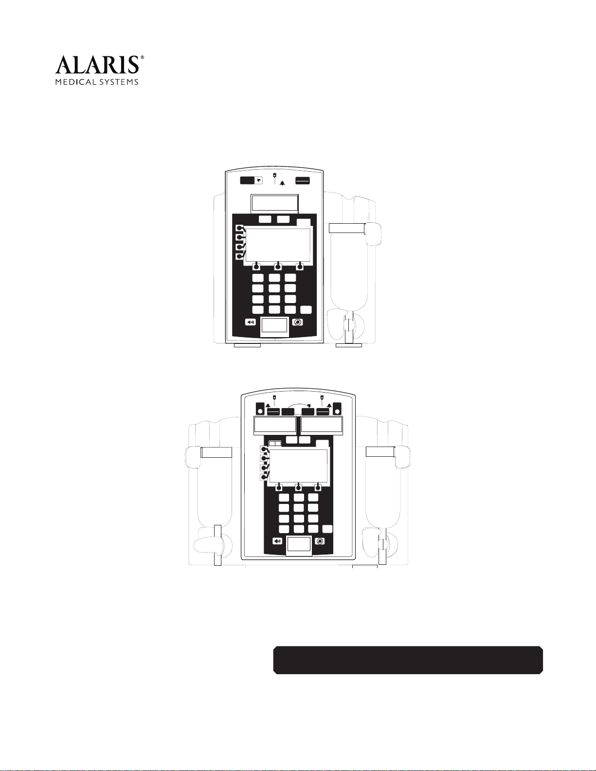
• Single-Channel, Models 7130/7131
• Dual-Channel, Models 7230/7231
• AccuSlide
®
Flow Regulator
administration sets
The Signature Edition
®
GOLD Infusion
System series includes the following
configurations:
• 7130B, 7130D, 7130E
• 7131A, 7131B
• 7230B, 7230D, 7230E
• 7231A, 7231B
Chapter 1 — GENERAL INFORMATION
1-1
Do not use sharp objects (pens, pencils, etc.)
to activate switches, as this will damage the
keypad.
Any attempt to service an ALARIS Medical
Systems instrument by anyone other than an
authorized ALARIS Medical Systems Service
Representative while the instrument is under
warranty may invalidate the warranty.
CAUTION
CAUTION
Signature Edition
®
GOLD Infusion System, Models 7130/7131 and 7230/7231
Technical Service Manual

1.1 INTRODUCTION (Continued)
7130/7131 and 7230/7231 Series:
• is a 100-240 VAC, 50/60 Hz instruments
family that supports both single and dual
channel fluid delivery
• features user-interactive software
• displays prompts, alarms and alert
messages, and troubleshooting
information on main LCD display
• can be configured to specific operational
requirements
• allows upgrades for future instrument
enhancements
• has been designed to interface with
accessory equipment.
7131/7231 Series key differences from
7130/7230 Series are:
• HARDWARE
The 7131/7231 Series is labeled for
220V with two power cord options and
has isolated RS-232 Board, potential
equalization (PE) connector, and drop
sensor board installed.
There is no Nurse Call option.
Keypads, other than English, have
symbols instead of words.
• SOFTWARE
The 7131/7231 Series has a drug list
only if the software version is 4.08 or
higher and profiles are enabled. Some
defaults are different in configuration
mode and there are several languages to
choose from in version 2.78.
Refer to the applicable Signature Edition
®
GOLD Infusion System DFU for complete
setup and operation information.
1.2 PRECAUTION DEFINITIONS
A is an alert to a potential
hazard which could result in serious
personal injury and/or instrument damage if
proper procedures are not followed.
A is an alert to a potential
hazard which could result in minor
personal
injury and/or instrument damage if proper
procedures are not followed.
1.3 SPECIFICATIONS
Refer to Table 1-1.
1.4 ACCESSORIES
Accessory items are available for use with
the instrument. These items are described
in the following paragraphs.
1.4.1 Nurse Call (7130/7230 only)
All instruments are equipped with the nurse
call feature. Alarms and some alerts from
the instrument will be relayed to the facility’s
existing nurse call system. No operating
features of the instrument are changed and
it will alarm with or without the nurse call.
The only additional item needed is a cable
with a 9-pin to mono phone jack (ALARIS
P/N 136111).
1.4.2 Learn/Teach RS-232 Cable
This is a standard commercially available
9-pin Null Modem RS-232 cable (ALARIS
P/N 133450). The Learn/Teach RS-232
cable is used to connect two instruments for
the purpose of transferring (downloading)
configuration data from/to another
instrument.
NOTE: Guardrails
®
Safety Software data
sets cannot be transferred via the
Learn/Teach function. They must be
downloaded directly from a PC.
GENERAL INFORMATION
1-2
WARNING
CAUTION
Signature Edition
®
GOLD Infusion System, Models 7130/7131 and 7230/7231
Technical Service Manual

GENERAL INFORMATION
1-3
Signature Edition
®
GOLD Infusion System, Models 7130/7131 and 7230/7231
Technical Service Manual
Administration Sets:
Use only ALARIS Medical Systems
®
72 Series administration sets. All
disposable IV set and IV set accessory models are defined on a separate
card.
Air-in-Line Accuracy:
Alarms:
• Accumulated Air in
Line
• Air in Line
• Battery Depleted
• Channel
Malfunction
• Computer Link
Failure
• Flow Sensor
Unplugged
• Hold Time
Exceeded
• Instrument
Malfunction
• Key Stuck
• Latch Open
• No Upstream Flow
Detected
• Occlusion
Downstream
• Occlusion Upstream
• Primary Flow
Detection During
Secondary
• Set Out
• Set Up Time
Exceeded
Altitude:
Operating Altitude: -500 ft. (-150m) to 7,500 ft. (2285m)
Battery:
Rechargeable nickel-cadmium (NiCad). Use only NiCad 12V, 1.8
ampere-hour (Ah) (minimum) batteries. A single channel instrument will
operate for 4 hours nominal and a dual channel instrument will operate
for 3 hours nominal, under the following conditions:
• new, fully-charged battery
• ambient room temperature 73 ± 7°F (23 ± 4°C)
• resistance monitoring modes
• rate: 100 mL/h on a single channel instrument and 50 mL/h on each
channel of a dual channel instrument.
Battery run time is affected by operating mode, rate, monitoring options,
and back pressure.
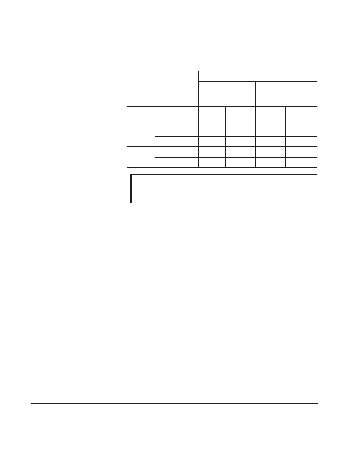
Table 1-1. Specifications
Configured Threshold Air Volume Detection Range
50µL 15µL - 85µL
100µL 35µL - 140µL
200µL 100µL - 235µL
500µL 275µL - 565µL
GENERAL INFORMATION
1-4
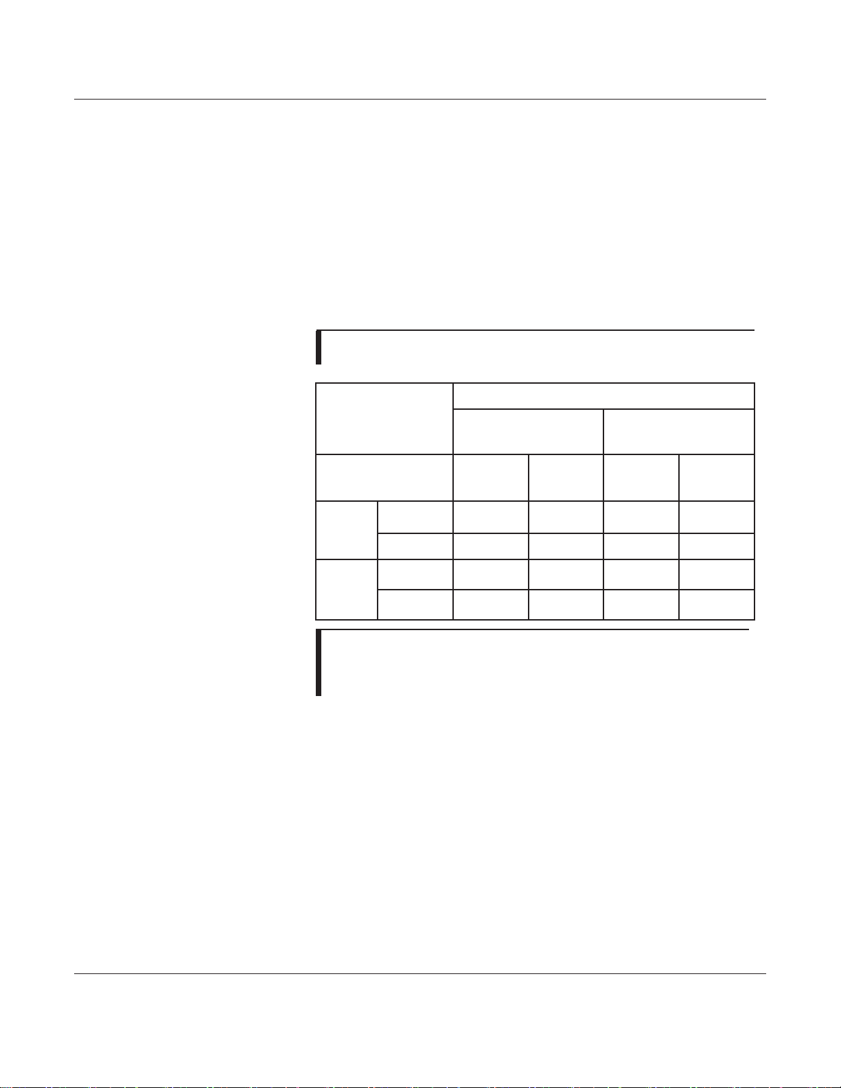
Table 1-1. Specifications (Continued)
Bolus Volume Limits:
NOTE: When the occlusion alarm pressure limit is set to the maximum
threshold setting, the maximum infusion pressure generated into a hard
occlusion at 25 mL/h is 11.6±3.9 psi. Testing performed using IV set
Model 72003, at 68±4°F (20±2°C).
Case:
Impact and flame resistant plastic.
Critical Volume:
Maximum incremental volume in case of single point failure will not
exceed 1.0 mL at 999.9 mL/h.
Dimensions (Nominal):
7130/7131 7230/7231
Width
Height
Depth §
Weight §§
Power Cord
§ without pole clamp
§§ without power cord
7.6 in/19.3 cm
8.6 in/21.8 cm
5.0 in/12.7 cm
6.6 lbs/3.0 kg
10 ft/3 m
10.7 in/26.7 cm
8.6 in/21.8 cm
5.0 in/12.7 cm
8.4 lbs/3.8 kg
10 ft/3 m
Environmental Conditions:
Operating Storage/Transport
Temperature Range
Relative Humidity
Atmospheric Pressure
5 to 40°C
(41 to 104°F)
20 to 90%
Non-condensing
700 to 1060 hPa
-40 to 60°C
(-40 to 104°F)
5 to 95%
Non-condensing
500 to 1060 hPa
Fluid Ingress Rating:
Drip proof IPX1
Time Bolus Volume
Released Upon Correcting
Downstream Occlusion
(mL)
Monitoring Options
Pressure
Resistance and
High Resistance
Threshold Settings
25
mmHg
600
mmHg
100%
25 mmHg
100%
600 mmHg
1 mL/h
Maximum 0.5 0.5 0.5 0.5
Typical <0.1 0.3 <0.1 <0.1
25 mL/h
Maximum 0.5 0.5 0.5 0.5
Typical <0.1 0.3 <0.1 <0.1
Signature Edition
®
GOLD Infusion System, Models 7130/7131 and 7230/7231
Technical Service Manual
GENERAL INFORMATION
1-5
Signature Edition
®
GOLD Infusion System, Models 7130/7131 and 7230/7231
Technical Service Manual
Table 1-1. Specifications (Continued)
Ground Current Leakage:
Electrical leakage current, enclosure: <100 microamperes
Electrical leakage current, patient: <10 microamperes
Log Capacity:
Software version 2.78:
2000 Event History Log
Software version 4.06/4.08:
300 Continuous Quality Improvement (CQI)
1500 Event History Log
Maximum Infusion Pressure:
16 psi
NOTE: Testing performed per proposed standard IEC 601-2-24 using
IVAC
®
IV sets.
Maximum Time to Alarm:
NOTE: When the occlusion alarm pressure limit is set to the
maximum threshold setting, the maximum infusion pressure
generated into a hard occlusion at 25 mL/h is 11.6±3.9 psi. Testing
was performed using IV set Model 72003, at 68±4°F (20±2°C).
Memory: 4.06 and higher: Maintains infusion perimeters indefinitely until the
instrument is reprogrammed.
2.78: Interrupted secondary or advanced operating modes retain special
program settings up to 6 hours. Resistance/pressure trending
information is retained for 6 hours.
Mode of Operation: Continuous
Number of Instruments
per Pole: 3 (713X), 2 (723X), single pole, weighted base, 5 legs.
Time to Detect
Downstream
Occlusion (minutes)
Monitoring Options
Pressure
Resistance and
High Resistance
Threshold Settings
25
mmHg
600
mmHg
100%
25 mmHg
100%
25 mmHg
1 mL/h
Maximum 2 75 2 7
Typical 0.6 30 0.6 4
25 mL/h
Maximum 1 25 1 3
Typical 0.1 1 1.0 1

GENERAL INFORMATION
1-6
Signature Edition
®
GOLD Infusion System, Models 7130/7131 and 7230/7231
Technical Service Manual
Occlusion Alarm Pressure:
12 ± 4 psi maximum
Parts per mL:
Precision Flow 3600 steps to deliver 1 mL Pressure Mode (rate < 50
mL/h). All other occlusion monitoring options 1150 steps to deliver 1 mL
(Cal # = 0.0) steps will vary with Cal #.
Power Requirements:
100-240 VAC, 50-60 Hz (40 W), 3-wire grounded system. Class 1 with
internal power source.
Rate Accuracy:
For rates greater than 1 mL/h, up to 999.9 mL/h: ±5%, 95% of the time
with 95% confidence, under the conditions listed below.
For rates equal to or less than 1 mL/h: ±6.5%, 95% of the time with 95%
confidence, under the conditions listed below.
Variations of head height, back pressure, time, monitoring mode option,
instrument tilt, or any combination of these, may affect rate accuracy.
Factors that can influence head height and back pressure are: IV set
configuration, IV solution viscosity and IV solution temperature. Back
pressure may also be affected by type of catheter.
Rate Range:
0.1 to 999.9 mL/h in 0.1 mL/h increments (primary)
0.1 to 270.0 mL/h in 0.1 mL/h increments (secondary)
RFI:
Tolerance < 10 V/m across frequency range.
Temperature:
Operating above 30°C, for extended periods will reduce battery life.
Volume to Be Infused Range:
0.1 to 9999.9 mL in 0.1 mL increments (primary and dose rate)
0.1 to 999.9 mL in 0.1 mL increments (secondary and loading dose)
0.1 to 999.9 mL per step in 0.1 mL increments (multi-step)
0.1 to 999.9 mL per dose in 0.1 mL increments (multi-dose)
WARNINGS (Alerts):
• Battery Low • Load Dose Complete
• Checking Line • Multi-Step Complete
• Complete Entry • Resistance Alert
• Computer Control Released • Secondary Complete
• Dose Complete • VTBI = 0
• Infusion in KVO
CAUTION
Table 1-1. Specifications (Continued)
NOTE: The Signature Edition
®
GOLD Infusion System has been assessed and complies with the following
Technical Standards: IEC 60601-1 / BS 5724, including amendments A1 and A2; IEC 60601-2-24; CISPR
11, Group 1, Class B Emissions; IEC 60601-1-2.
Infusion rate range:
0.1 to 999.9 mL/h
Head height: 24 ± 1 in.
(61 ± 2.5 cm)
Environment temperature:
68±8°F (20±4°C)
Back pressure: 0 psi.
Test solution: distilled water Set Model: 72003
Needle: 18 gauge Minimum collection volume: 6 mL

GENERAL INFORMATION
1-7
Signature Edition
®
GOLD Infusion System, Models 7130/7131 and 7230/7231
Technical Service Manual
1.4 ACCESSORIES (Continued)
1.4.3 Flow Sensor
Flow sensor capability is available with an
upgrade kit for the 7130/7230 (refer to the
“Illustrated Parts Breakdown” chapter). For
7131/7231, all that is needed is a flow
sensor.
The flow sensor attaches to the
administration set's drip chamber. It detects
an empty solution container and verifies
fluid flow. When installed, it will allow VTBI
to be turned off. The flow sensor will not
see drops falling if the drip chamber is tilted
more than 24°.
1.5 ALARMS, ERRORS, MESSAGES
Alarm messages are displayed on the Main
Display. Refer to the applicable Signature
Edition
®
GOLD Infusion System DFU for
detailed information.
1.5.1 Silencing Alarms
All alarms can be temporarily silenced by
pressing the Silence Key.
1.6 BATTERY MANAGEMENT SYSTEM
This section contains general information on
the battery management system. Included
is information on how the Battery Manager
monitors and maintains the battery, controls
the power on/off for the rest of the
instrument, and provides support functions
for the main processor. Refer to the
“Principles of Operation” chapter for more
detailed functional descriptions.
The battery management system consists of
the Battery Manager IC and various sensors
and signal processing circuits. The Battery
Manager IC (Rev. 3.06) is a custom-
programmed microcontroller that performs
the following functions:
• Controls battery charger
• Provides a battery status "battery gauge"
• Monitors voltage and temperature of
battery
• Controls instrument power source (on/off
function)
• Drives Lower LCD Display
(refer to Figure 1-2)
• Includes a relative-time clock
The Battery Manager communicates with
the main processor via a serial data
channel. The main processor issues
commands to the Battery Manager which
then responds with status information and
data using this channel.
1.6.1 Fan
The internal fan is used for cooling, mainly
to help prolong battery life. It is a ball-
bearing, brushless DC fan. The fan is
always on when the battery is charging with
"Fast" or "Top-up" charge. The fan will go
on any time battery temperature is over
22°C.
1.6.2 Battery and Charging Process
The battery is a ten-cell (1.2V per cell), high
capacity nickel-cadmium type rated at
12 volts and 1.8 amp-hours (with a minimum
of 500 charge cycles).
The battery pack (10 to 18V) has a built-in
temperature sensor which allows the Battery
Manager to monitor the temperature of the
battery. The pack also includes a
temperature-limiting thermostat which opens
the circuit if the battery temperature gets too
hot and closes again when the temperature
returns to normal.

GENERAL INFORMATION
1-8
Signature Edition
®
GOLD Infusion System, Models 7130/7131 and 7230/7231
Technical Service Manual
1.6 BATTERY MANAGEMENT SYSTEM
(Continued)
1.6.2 Battery and Charging Process
(Continued)
The battery charge circuit charges the
battery with a constant current of 1 ampere
whenever the Battery Manager turns the
charger on. The Battery Manager regulates
average charge current by turning the
charger on and off with the appropriate duty
ratio. The battery charge cycle consists of
four modes; fast charge, top-up charge, float
charge, and hot charge.
• Fast Charge
: Fast charge is initiated
whenever the battery is less than 36°C,
and has been discharged by more than
200 Ampere-seconds through actual use
or self discharge. Leaving the instrument
unplugged for a day would cause about
200 Ampere-seconds of self discharge.
The charge current is a continuous
1 Ampere. The end of a fast charge is
detected when the temperature of the
battery rises 7°C above its temperature
at start of charge and is at least 30°C, or
when the battery voltage declines by
192mV below its peak value, or total
charge time exceeds 3.2 hours. Refer to
“Battery Charge Regulator” section in the
“Principles of Operation” chapter for
further details.
•T
op-Up Charge: The top-up charge
phase begins at the end of the fast
charge phase and finishes adding the
last few percent of charge to the battery
and balances individual cell charges.
This phase charges at an average rate of
180 mA (1 A for 0.9 seconds every 5
seconds) for 180 minutes. At that time,
the instrument will go into float charge
mode.
The charger will suspend top-up if the
battery temperature exceeds 37°C. The
time spent to cool down to below 37°C is
in addition to the 180 minutes top-up
charge time. If top-up cool down time
exceeds 5 1/2 hours, the instrument will
go into float charge mode.
• Float Charge
: The float charge phase
begins at the end of the top-up phase
and helps maintain a fully charged
battery. This phase charges at an
average rate of 40 mA (1A for 0.2
seconds every 5 seconds). The fan
remains on or turns on when battery
temperature exceeds 22°C.
• Hot Charge
: The hot charge mode occurs
when the instrument determines that the
battery is >36°C (normally due to
ambient temperature being >27°C) to
allow a charge after waiting 3 hours for it
to cool down. Hot charge mode charges
at an average rate of 180 mA (1A for 0.9
seconds every 5 seconds) for a total
charge time of 18 hours. If the battery
temperature exceeds 43°C, the charging
is turned off until the temperature falls
below 43°C.
Note that the cool down time is in
addition to the 18-hour charge time. The
float charge cycle begins at the end of
the hot charge cycle.
1.6.3 Refresh Cycle
A battery refresh cycle performs a full
charge, discharge, and recharge to
condition and measure the capacity of the
battery. This refresh results in a new
"Measured Capacity" in the battery
diagnostics and can be used to judge the
condition of the battery.
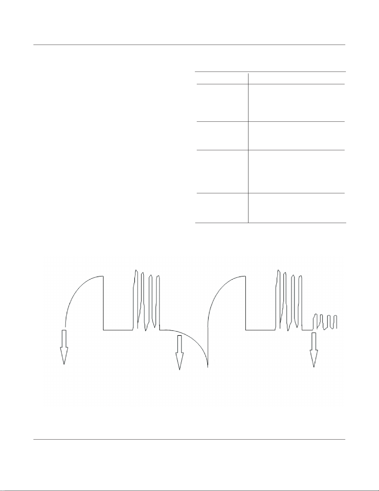
Battery Voltage Instrument Response
12.0V (Single)
12.1V (Dual)
• One tick mark left on gauge
• Instrument continues to function
• Warning tone activated
• Low battery warning
11.45V • Instrument does not pump
• Constant alarm
• Low battery alarm (depletion)
10.25V • 1 minute or longer (nominal 5
min.) after low battery alarm
• Backup speaker activated
• Instrument shutdown (5 min.
after alarm)
9.75V • No AC power applied
• Battery disconnected from
circuit by shutdown signal
GENERAL INFORMATION
1-9
Signature Edition
®
GOLD Infusion System, Models 7130/7131 and 7230/7231
Technical Service Manual
1.6 BATTERY MANAGEMENT SYSTEM
(Continued)
1.6.3 Refresh Cycle (Continued)
The refresh cycle must be initiated
manually, either by disconnecting/
reconnecting the battery or by loading 0.0
Ah as the rated capacity in the battery
diagnostics page. After the zero rated
capacity is loaded and the OK soft key is
pressed, the original rated capacity must be
reloaded to preserve the battery gauge.
The empty ("E") icon will flash during the
discharge part of the refresh cycle (see
Figure 1-1). Important: The AC power must
remain connected and uninterrupted during
the discharge cycle. If the AC power is
removed during this cycle, the discharge
cycle will be terminated and another refresh
cycle will have to be initiated. The time for
complete refresh is dependent upon battery
Figure 1-1. Battery Refresh Cycle
Table 1-2. Battery Trip Points
Refresh cycle starts
“E” blinks
Cycle ends
11.45 Volts
Fast Fast
Cool* Cool*
Top-Up*Top-Up*
FloatDischarge
* Cool and Top-Up portions of cycle will vary with
temperature. The complete cycle could last 24 hours if
instrument turned on with the Fan running most of the time.

GENERAL INFORMATION
1-10
1.6 BATTERY MANAGEMENT SYSTEM
(Continued)
1.6.3 Refresh Cycle (Continued)
temperature and takes an average of 20
hours to complete (refer to Figure 1-1).
Two ways to initiate a manual refresh cycle
are:
• Disconnect from AC, unplug battery, and
then press power switch. Lower LCD
will go blank. Reconnect battery and
then reconnect instrument to AC.
• Enter Diagnostics Mode, go to page D2,
Select Battery Status, and enter 0.0 Ah
for battery-rated capacity. Press Enter
and ok. Turn instrument off and back on,
and then reconnect to AC. Once the fan
turns on (indicating start of a refresh
cycle), return to page D2 and reset
battery rated capacity to 1.3 Ah.
1.6.4 Battery Gauge
The battery gauge provides an indication of
the approximate amount of charge
remaining on the battery. It will usually
indicate less charge than is actually
available with a new battery. This is
displayed in a bar graph format on the
lower LCD Display and is active as long as
the battery is connected to the instrument.
(Refer to Figure 1-2, Lower LCD Display
Layout.)
The battery gauge circuitry measures the
current flow into and out of the battery and
maintains a record of the state of charge of
the battery. This record is reset each time
the instrument completes a full refresh
cycle. The battery gauge uses this record,
together with a measurement of the present
power requirements of the instrument, to
estimate the charge available on battery
power at the current infusion rate.
NOTES:
• The instrument label and battery gauge
are always displayed, even when the
instrument is turned off; however, the
battery gauge does not represent the
battery charge remaining when the
instrument is turned off.
• To ensure a more accurate battery gauge
reading, review the battery gauge five
minutes after starting an infusion. The
gauge updates for each program change
while infusing. Battery run time may be
affected by the operating mode, rate,
monitoring options and back pressure.
1.6.5 Power On/Off
The Battery Manager provides the interface
between the power on/off switch(es) and
the main processor. When the instrument
is off, the Battery Manager interprets either
power switch as a turn on command and
applies power to the rest of the instrument,
informing the main processor which switch
was pressed. Once power is on, further
presses of a power switch are passed on to
the main processor which determines the
appropriate response under the existing
conditions. If the response is to turn the
power off, the main processor requests that
the Battery Manager remove power from
the rest of the instrument.
If an error has been detected which causes
the watchdog to be in alarm, pushing the
power switch (or for dual channel
instruments, either power switch)
immediately causes the power to be turned
off, without intervention by the Battery
Manager.
Signature Edition
®
GOLD Infusion System, Models 7130/7131 and 7230/7231
Technical Service Manual
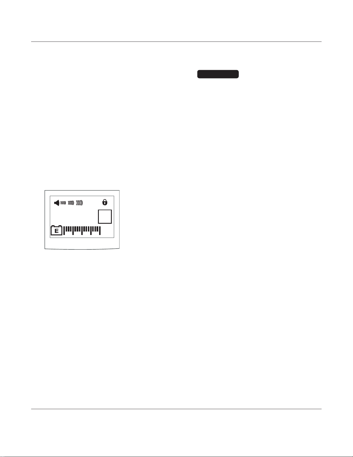
GENERAL INFORMATION
1-11
Signature Edition
®
GOLD Infusion System, Models 7130/7131 and 7230/7231
Technical Service Manual
1.6 BATTERY MANAGEMENT SYSTEM
(Continued)
1.6.6 Lower LCD Display
The Battery Manager also contains the
driver for the Lower LCD Display. In addition
to the battery gauge, this display contains a
four-character alphanumeric "configuration"
display and several icons. The information
for these other displays is controlled by the
main processor and is communicated to the
Battery Manager through the serial channel.
The Battery Manager also uses the four-
character display to indicate errors detected
in the Battery Manager system itself.
1.6.7 Clock
The Battery Manager provides a "relative
time" clock which the main processor can
set and read. This clock consists of a 32-bit
counter which is incremented once a
second under all conditions. The main
processor uses this counter as a means of
determining elapsed time even when power
has been turned off. The clock is used to
compensate for normal battery capacity
degradation over time.
1.6.8 Battery Maintenance
Several features have been included in the
Battery Manager to help properly maintain
the battery.
• A battery capacity measurement is
available in diagnostic mode.
• A special circuit removes all load from
battery when voltage falls too low,
preventing damage from over discharge
due to long-term storage.
NiCad batteries can be stored indefinitely
with no load but will self-discharge from a
charged state in about 100 days. This does
not damage the battery as it would if it were
a lead acid-type battery. Connect
instrument to AC to recharge batteries.
MNTR
GOLD
Figure 1-2. Lower LCD Display Layout
• Use only batteries approved by ALARIS
Medical Systems, due to Battery
Manager requirements and the
thermostat contained in the battery
assembly. If the instrument has been in
storage, connect it to AC power before
turning it on. Usually one refresh cycle
is sufficient to restore battery capacity.
If necessary, repeat the procedure at
24-hour intervals, 2 or 3 times, to
increase capacity.
• Battery replacement should be
performed by qualified service
personnel while instrument is not in use.
DO NOT open, incinerate or short circuit
the battery. Worn-out batteries must be
disposed of properly, according to local
regulations.
CAUTIONS

GENERAL INFORMATION
1-12
1.6 BATTERY MANAGEMENT SYSTEM
(Continued)
1.6.8 Battery Maintenance (Continued)
NOTE: If under load (inside instrument), the
maximum storage time would be about 130
days before electrolyte extrusion occurs past
the battery seal.
If the battery exhibits short run times, a
reconditioning procedure can be used:
1. Disconnect battery and AC
2. Press On/Off switch and verify lower
LCD goes blank.
3. Reconnect battery.
4. Reconnect instrument to AC. A refresh
cycle will be initiated.
5. Repeat this procedure at 24-hour
intervals, 2 or 3 times, to increase
capacity or use a battery conditioner.
1.7 NICAD BATTERY CAPACITY
INFORMATION
All batteries have specific conditions under
which they are guaranteed to meet their
published specifications. Deviations from
these conditions typically result in a
reduction of available capacity.
Manufacturers of NiCad batteries rate
capacities, usually expressed in Ah, based
on a specified "ideal" charge and discharge
condition, as well as the use of a "new"
battery. Battery manufacturers do not use
the calendar year for battery date codes.
The battery date code year starts on
September 1. The first two digits of the date
code are for the year and the last two digits
are for the week of the year (for example,
date code 0411 = the year 2004 and the
eleventh week from September 1).
An ideal charge cycle starts with a fully
discharged battery charged at C/10 (C is the
rated capacity in Ah) constant current for 15
hours while at room temperature. For
instance, a 1.8Ah battery would be charged
for 15 hours at 180mA constant current with
a room temperature of 23°C.
The ideal discharge starts with a fully
charged battery under a C/5 constant
current load at room temperature,
discharging to a cell voltage of 0.9V. The
rated capacity is then calculated as the time
to discharge divided by 5. Again, a 1.8Ah
cell would be discharged at 360mA constant
current and not reach 0.9V for at least 5
hours. Note that a given battery type has
different capacities based on the load. For
instance, a battery rated at 1.8Ah at a
360mA load may have only 1.6Ah at a
1600mA load.
As can be seen from the preceding ideal
conditions, there are many conditions which
can affect the battery capacity. The
following conditions have the most practical
impact on battery capacity delivered in this
instrument.
•T
emperature During Charge:
As the effective ambient temperature of
the battery increases, the amount of
charge that the battery will accept is
decreased. At an ambient temperature of
35°C, an enclosed battery will
temporarily accept only about 90% of the
charge it would otherwise accept at
23°C. Because the batteries are internal
to the instrument case and the instrument
itself generates heat, the batteries will be
exposed to temperatures above room
temperature. Some of the ways the
instrument limits the temperatures that
the battery sees include forcing air
across it (an internal fan) and turning off
the charger when the battery temperature
gets too high.
Signature Edition
®
GOLD Infusion System, Models 7130/7131 and 7230/7231
Technical Service Manual

GENERAL INFORMATION
1-13
Signature Edition
®
GOLD Infusion System, Models 7130/7131 and 7230/7231
Technical Service Manual
1.7 NICAD BATTERY CAPACITY
INFORMATION (Continued)
• Cycle Life and
Aging:
As batteries get older and go through
many charge/discharge cycles, batteries
"wear out," in that the chemicals and
materials used to construct the cell break
down. The way the instrument deals with
this is to assume that a battery will
continually reduce capacity at a rate
equivalent to 30% over 4 years, and
continually reduce capacity at a rate
equivalent to 30% per 200 full charge
cycles. These calculated values are
used to reduce the displayed runtime on
the battery gauge.
• Partial Discharge/Charge:
When a battery is partially discharged,
then charged for less than the full time,
differences between individual cell
capacities result in cells completing
charge at different times. If the full
charge sequence is not then completed,
the cell "mismatch" becomes
progressively greater. This is viewed by
the user as low apparent runtimes and
premature low battery warning and
alarms.
The problem is cumulative in that the
mismatch increases for every partial
cycle. The lowered capacity is not
permanent, but may require 2-3 full
charge cycles to recover. The way the
instrument deals with this is to reduce the
displayed runtime based on a limited
history of partial cycles.
• Charge Rate:
The ideal charge rate requires 15 hours
to get to full charge, which is undesirable
from the user's perspective. The
instrument provides a multiphase charge
cycle which results in about 80% capacity
in the first 2 hours after fast charge. The
next charge phase, top-up, is designed to
finish the charge and to bring all
individual cells to the fully charged state,
essentially rematching them. Refer to
“Battery and Charging Process” section
in this chapter for “Fast Charge” and
“Top-up Charge” information. If the
top–up charge is not completed, then the
cell mismatch is not reduced and the
cumulative capacity reduction occurs.
Top-up is a 3-hour charge, but the
elapsed time to complete it may be over
5 hours, as the charger is turned on and
off to keep the battery cool during that
time.
• Battery
Alarm Voltage:
The battery alarm voltage is the voltage
at which the instrument stops operating
and generates an alarm indicating the
instrument needs to be connected to AC
power. As noted in the ideal discharge
condition, the end of discharge is
determined by 0.9V/cell.
Under perfect conditions, a battery of 10
cells connected in series would reach the
end of discharge at 9.0V; however, cells
are not perfectly matched so some will
reach 0.9V before others. The problem
occurs when a cell in series with other
cells can go below 0.9V and actually can
go into cell reversal, which permanently
damages the particular cell. On the other
hand, increasing the alarm voltage to
compensate for imperfectly matched cells
results in reduced runtimes with available
capacity.

1.7 NICAD BATTERY CAPACITY
INFORMATION (Continued)
The user sees this as premature low
battery warnings and alarms. The way
the instrument deals with this is to
increase the alarm voltage to guarantee
the battery is not damaged and to reduce
the assumed capacity to below that
printed on the battery. The battery gauge
is intended to show the minimum run
time left on the battery taking all these
factors into account.
NOTE: In the event ALARIS Medical Systems
provides different battery packs in the future,
the replacement battery may have a different
rated capacity. Therefore, the Battery
Manager of the instrument needs to know that
a new battery has been added and the rated
capacity has changed. Refer to the
“Removing Battery” section of “Corrective
Maintenance” chapter and the “Changing
Rated Capacity of Battery” section of
“Troubleshooting” chapter.
1.8 DYNAMIC MONITORING
®
SYSTEM
(DMS)
The following is general information
regarding the Dynamic Monitoring
®
System.
In order for fluid to move through the
administration set, a pressure difference
(gradient) must exist. In a gravity setup, this
is done by head height. In a pump, the
instrument will develop pressure to
overcome downstream effects on fluid flow.
The fundamental concept behind the
Dynamic Monitoring
®
System is that the
resistance to fluid flow from the mechanism
to the patient's infusion site can be
measured. This is done by intentionally
varying the flow rate while monitoring the
resulting changes in fluid pressure (refer to
Figure 1-3 "Resistance Graph"). Signal
processing of the pressure and flow data
can then produce the fluid impedance value.
Such measurements can be made
continuously at short intervals and be
independent of the selected rate. Head
height and resulting pressure variations,
likewise, will not affect the measurement.
When a complete occlusion occurs, the
resistive part of the fluid impedance is very
large (theoretically infinite). Elevated
resistances due to clotting, clogged filters,
partial occlusions or infiltrations can be
measured.
The Dynamic Monitoring
®
System provides
a means to measure the mechanical
properties of the downstream flow path.
Figure 1-3. Resistance Graph
Pressure =
Effect when a force is against a restriction.
Resistance =
Caused when impediment to fluid flow
occurs.
Resistance = Change in Pressure (
∆P)
Change in Flow ( ∆F)
Refer to Figure 1-4 "Pressure and Resistance
Graph".
GENERAL INFORMATION
1-14
Signature Edition
®
GOLD Infusion System, Models 7130/7131 and 7230/7231
Technical Service Manual
F Nominal
0
FLOW (cause)
RATE HI
RATE LO
W
SET RATE
PRESSURE (result)
P
F
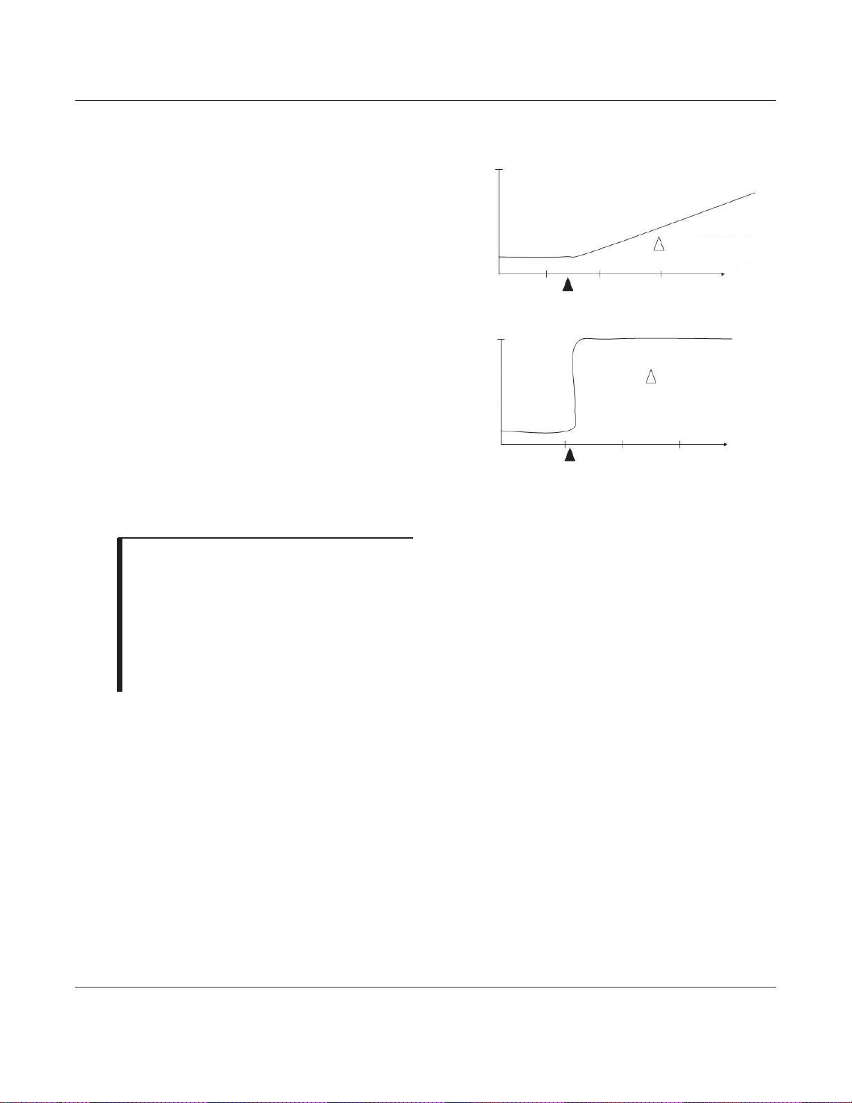
GENERAL INFORMATION
1-15
Signature Edition
®
GOLD Infusion System, Models 7130/7131 and 7230/7231
Technical Service Manual
1.8 DYNAMIC MONITORING
®
SYSTEM
(DMS) (Continued)
Features include:
• Alarm setting is based on dynamic
system impedance (pressure changes,
not absolute pressure).
• Detection of complete occlusions.
• Reduced nuisance alarms by minimizing
artifact effects such as head height and
patient movement.
• AutoRestartPlus feature allows
instrument to automatically continue
operation if an occlusion is cleared within
self-check period (40 seconds). A
warning tone and “Checking Line”
message will occur for up to 40 seconds.
The feature can be turned off (set
restarts to zero), or number of restarts
may be set from 1 to 9.
NOTES:
• The restart counter is reset whenever
Run/Hold is pressed, the instrument or
channel is turned off or an alarm occurs.
• When infusion is started, the resistance
may be other than 0%, depending on
solution viscosity, catheter/tubing size and
filters.
• Resistance Alert provides an early
warning of slow or gradual changes in
resistance of IV line/site. Resistance Alert
marker can be set from 5 to 100%. It
allows resistance to be monitored and
provides a tone every 30 seconds if
percent resistance exceeds resistance
alert mark.
• Resistance display may be turned off. If
off, system continues to monitor
downstream resistance and alarm
appropriately.
Figure 1-4. Pressure and Resistance Graph
Pressure rise is quite small with site
complication, especially with low flow rates.
Resistance rises dramatically with site
complication.
OCCLUSION
PRESSURE mmHg
IN PRESSURE
TIME
0
300
600
OCCLUSION
IN PRESSURE
TIME
FLUID OHMS
mmHg/Liter/Hr
100%
0
50%
75%

GENERAL INFORMATION
Signature Edition
®
GOLD Infusion System, Models 7130/7131 and 7230/7231
Technical Service Manual
1-16
1.9 DATA COMMUNICATIONS FUNCTION
The instrument has built-in remote
monitoring capability. This allows features
and their data to be monitored by a
computer, providing a means to create
advanced clinical systems. A separate
manual on data communications is available
and organized to support technical
personnel with a wide range of experience
and needs. The separate manual includes:
• General Information: Includes phone
number for technical support.
• Operation: Instrument's communications
modes, controls, indicators, and
procedures from user's point of view.
• Instrument Setup: How to set the baud
rate, enable or disable computer
monitoring, and other parameters.
• Electrical Interfacing: RS-232
background information, connectors and
recommended wiring for common
computers.
• Communications Protocol: Inquiry,
response, and command codes, data
formats, message sequences, and error
detection.
1.10 TRUMPET AND START-UP CURVES
Refer to the applicable Signature Edition
®
GOLD Infusion System DFU.

GENERAL INFORMATION
Signature Edition
®
GOLD, Models 7130/7131 and 7230/7231
Technical Service Manual
1-17
Table 1-3. Abbreviations, Acronyms, Symbols
Various abbreviations, acronyms and symbols are used throughout this manual. The following are those that are
not commonly known or easily recognized.
* "active Low" logic signal VAO voltage alternating oscillator
AlL air-in-line VBKUP voltage backup
DFU directions for use VNEG negative voltage
DS display VMEAS voltage measured
ECD empty container detection VMOTOR voltage to motor
F fuse VPOS positive voltage
FB ferrite bead VRAW voltage raw (unregulated voltage)
H hexadecimal VTBI volume to be infused
KVO keep vein open VTHRES voltage threashold
PM preventive maintenance WD watchdog
PR power regulator WDI watchdog input
PRI/SEC primary to secondary WDO watchdog output
SCU serial control unit
 Loading...