


PCAM
IVAC® PCAM®Syringe Pump
Technical Service Manual

This manual has been prepared for use by qualified service personnel only.
Cardinal Health cannot accept any liability for any breakdown or deterioration in
performance of parts or equipment resulting from unauthorised repair or modification.
t Cardinal Health, 1180 Rolle, Switzerland
Alaris®, IVAC® and PCAM® are registered trademarks of
Cardinal Health, Inc. or one of its subsidiaries.
All other trademarks belong to their respective owners.
© 2005-2006 Cardinal Health, Inc or one of its subsidiaries. All rights reserved.
IVAC® PCAM® Syringe Pump 2/106 1000SM00017 Issue 2

Contents
Chapter 1 Introduction & Start Up 4
Chapter 2 Configuration & Calibration 13
Chapter 3 Routine Maintenance 26
Chapter 4 Troubleshooting 38
Chapter 5 Circuit Descriptions 42
Chapter 6 Spare Parts Replacement Procedures 47
Appendix A Specifications 83
Appendix B Spare Parts Listing 90
Appendix C Configured Options & Drug Protocol Rec. 97
Appendix D Service Centres 100
Appendix E Disposal 102
Appendix F Document History 105
IVAC® PCAM® Syringe Pump 3/106 1000SM00017 Issue 2

Introduction & Start Up
In this chapter
Introduction 5
Chapter 1
General Precautions 6
Front Panel, Controls and Indicators 7
Main Display 8
Loading a Syringe 9
Starting the Pump 10
Modifying a Preset Protocol 10
Basic Features 11
Printer Set Up 12
Patient Hand Set 12
Introduction & Start Up
Introduction
The IVAC® PCAM® Syringe Pump is designed to provide a small, self-administered dose of analgesic, as and when the patient demands
it by activating a hand operated button. The clinician can select limits for various parameters, including the size of each individual
dose, the minimum time between doses and the number of doses allowed during a period. In parallel to the patient controlled
operation the pump allows the clinician to set an automatic loading dose which will be delivered at the onset of treatment. Similarly a
continuous background infusion which is delivered irrespective of the patients demands for analgesia, can also be selected.
In addition, the pump will automatically record valuable information about each patients treatment and their individual demands for
analgesia. This allows further analysis of the frequency with which analgesia is being requested, the total dose delivered etc.
Product Familiarity
Prior to operation of the pump and prior to attempting any repairs or servicing, carefully read the Directions for Use (DFU)
As part of continuous improvement, product enhancements and changes are introduced from time to time.
Purpose of this Manual
This Technical Service Manual describes how to set up, test and maintain the IVAC® PCAM® Syringe Pump. This manual is intended for
use by personnel experienced in medical equipment testing and maintenance procedures .
Conventions Used in this Manual
BOLD Used for pump Display names, access codes, controls and indicators referenced in this manual, for
example, GENERAL OPTIONS menu, access code 251, LOCK 1 keyswitch.
'Single quotes' Used to indicate cross-references made to another section of this manual. For example, see Chapter
2, 'Configuration & Calibration'.
underline Used to indicate links to another section of this manual.
Italics Used to refer to other documents or manuals. For example, refer to the relevant Directions for Use (DFU)
for further information. Also used for emphasis, for example, ...position the narrow end of the tool...
Wherever this symbol is shown a Hints & Tips note is found. These notes provide useful advice or
information that may help to perform the task more effectively.
Wherever this symbol is shown a Toolbox note is found. These notes highlight an aspect of test or
maintenance that is important to know about. A typical example is drawing attention to a software
upgrade that should be checked that it has been installed.
IVAC® PCAM® Syringe Pump 5/106 1000SM00017 Issue 2

General Precautions
Prior to using this pump, carefully read the Operating Precautions described in the Directions for Use (DFU).
w
This pump contains static-sensitive components. Observe strict precautions for the protection of static
sensitive components when attempting to repair and service the pump.
An explosion hazard exists if the pump is used in the presence of flammable anaesthetics. Exercise care to
locate the pump away from any such hazardous sources.
Dangerous Voltage. An electrical shock hazard exists if the casing of the pump is opened or removed. Refer
all servicing to qualified service personnel.
This pump is protected against the effects of high energy radio frequency emissions and is designed to
be fail safe if extremely high levels of interference are encountered. Should false alarm conditions be
M
encountered, either remove the source of the interference or regulate the infusion by another appropriate
means.
If the pump is dropped, subjected to excessive moisture, humidity or high temperature, or otherwise
suspected to have been damaged, remove it from service for inspection by qualified service personnel.
Introduction & Start Up
IVAC® PCAM® Syringe Pump 6/106 1000SM00017 Issue 2
Introduction & Start Up
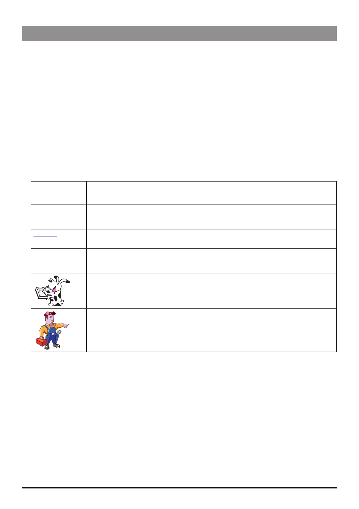
Front Panel, Controls and Indicators
Front Panel
Controls and Indicators
H
R
Q
S
START Press to start the infusion. The green
LED will flash during infusion.
STOP Press to stop/hold the infusion. The
amber LED will be lit while on hold.
BATTERY When illuminated, indicates that
the pump is running on the internal
backup battery. When flashing,
indicates that the battery power is
low, with less than 30 minutes of use
remaining.
AC POWER When illuminated, indicates that the
pump is connected to an AC power
supply and the battery is being
charged.
PLUS/MINUS
BUTTONS
ARROW
BUTTONS
Use to move cursor and to increase
or decrease values shown on main
display.
Use as softkeys in conjunction with
the prompts shown on the display.
For example, to select the CALIBRATE
option.
W
HISTORY Press to display PCA demands
J
PRINT Press to print patient history.
LOCK 1 Insert key into LOCK 1
OFF
SET
RUN
LOCK 2 Insert key into LOCK 2 and
PURGE/
BOLUS
Press and hold both buttons to
purge the extension set during
set up. See 'Basic Features' for
further information.
and drug infused history
graphs, 24 hour review and
event log.
Note: A suitable printer must be
connected to the pump.
keyswitch and turn key to
switch between OFF, SET and
RUN positions.
OFF - Turns the power off.
SET - Use to select or modify
protocols and to access
configuration and test routines.
RUN - Use to start the infusion.
Note: Switching from RUN
mode to SET mode without
first pressing the STOP button
automatically stops the
infusion.
turn key clockwise to open the
syringe cover.
This key lock is located
on the left side of the
pump
IVAC® PCAM® Syringe Pump 7/106 1000SM00017 Issue 2
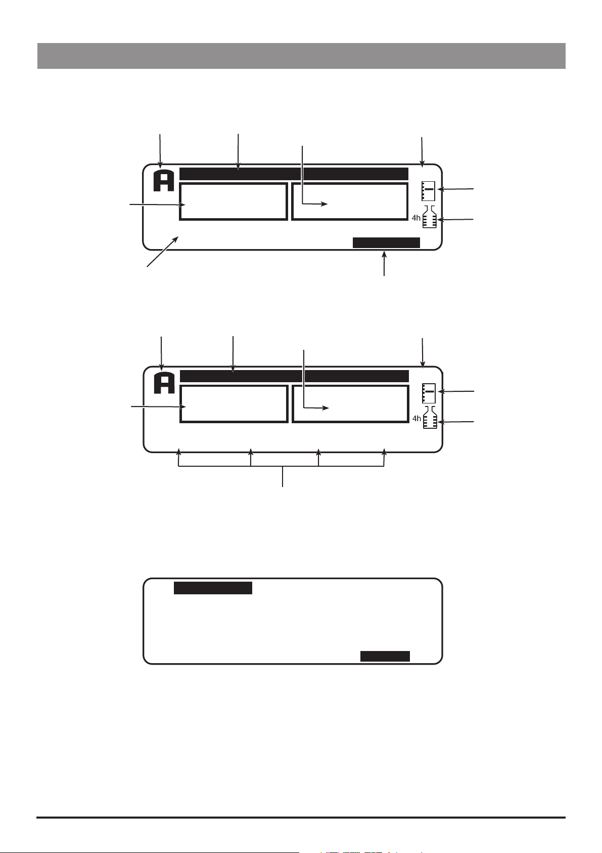
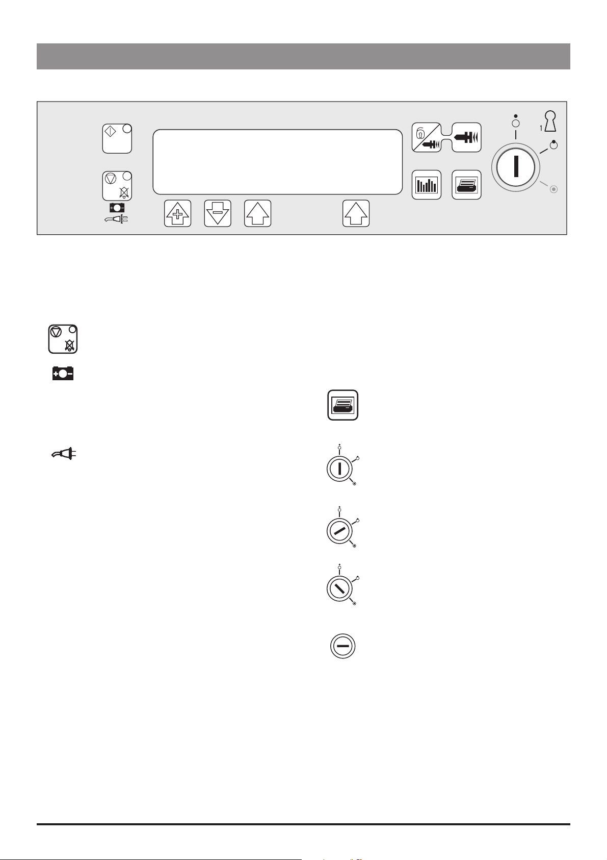
Main Display
Main Display
Example Software V3R2
Introduction & Start Up
Current Protocol
PCA Demand
Status
Syringe Type/Infusion Rate
Example Software V2R8
Current Protocol
PCA Demand
Status
PCA AVAILABLE
TOTAL
GOOD
BD PLASTIPAK
50 ml
PCA AVAILABLE
TOTAL
GOOD
MORPHINE 1
1.0 mg/ml
Pump Status
DEMANDS
Pump Status
DEMANDS
PCA DOSE
1.0 ml
Volume Infused
(Mass/Volume)
1
1
Volume Infused
(Mass/Volume)
1
1
DRUG INFUSED
1.0 μg
0.1 ml
View Protocol Summary
DRUG INFUSED
1.0 ug
0.5 ml
LOCKOUT
5 min
PROTOCOL
CONTINUOUS
0.0 ml/h
Time
13:07
Pumping
Pressure Icon*
Maximum
Dose Icon*
Time
13:07
Pumping
Pressure Icon*
Maximum
Dose Icon*
Protocol Summary Screen
Example: Software V3R2 only
PROTOCOL
MORPHINE
1.0 mg/ml
LOADING
0
μg
* These icons are not displayed when disabled.
DOSE LIMIT
50.0 mg IN 4 h
Protocol Summary
PCA DOSE
1.0 mg
LOCKOUT
2 min
CONTINUOUS
0
μg/h
DOSE RATE
STAT
QUIT
IVAC® PCAM® Syringe Pump 8/106 1000SM00017 Issue 2
Introduction & Start Up
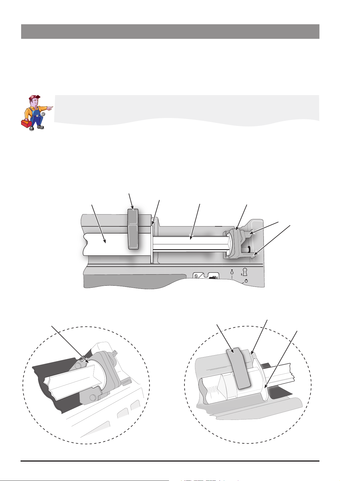
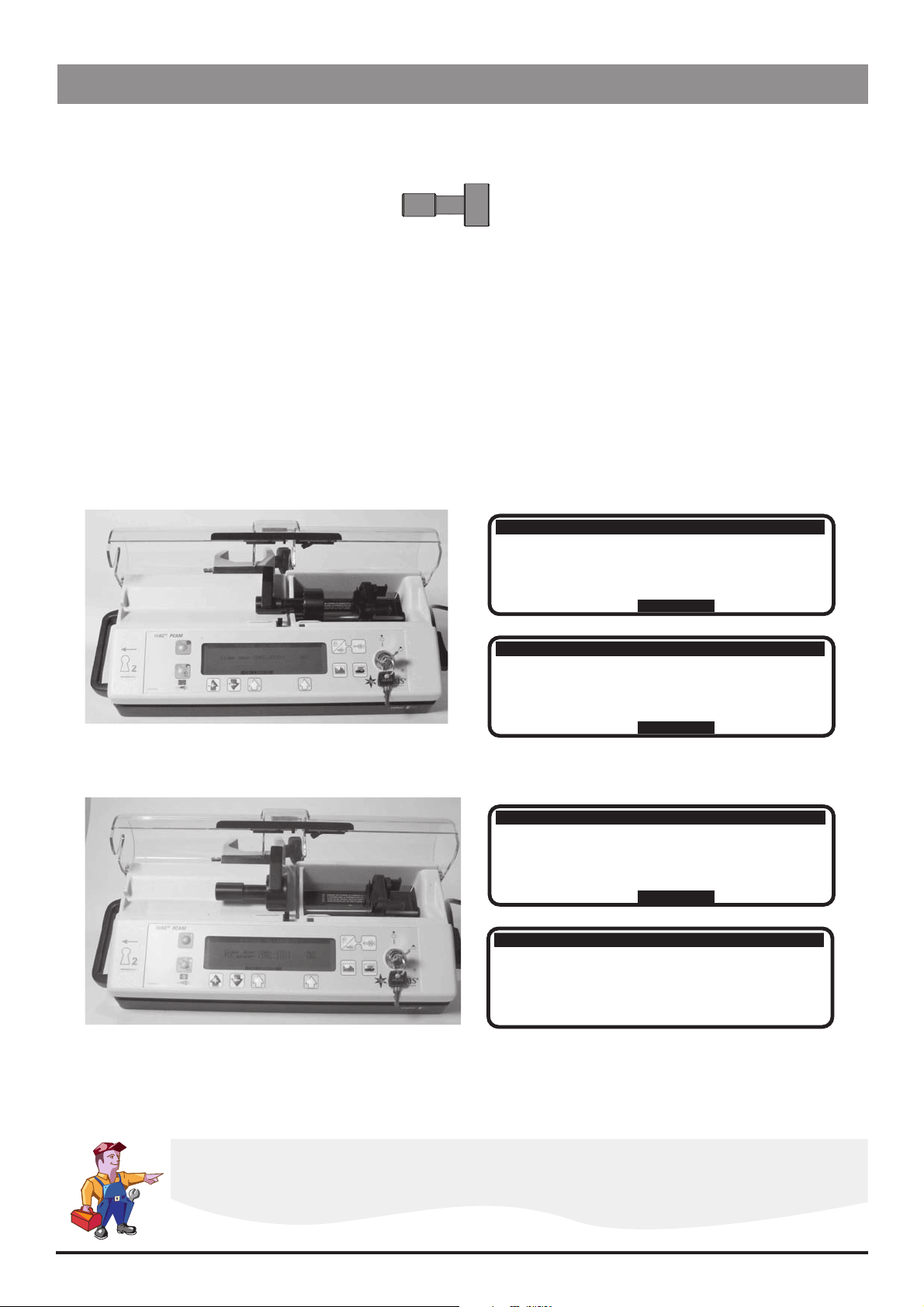
Loading a Syringe
1. Open the cover by turning the key in LOCK 2.
2. Squeeze the finger grips together on the plunger holder and slide the mechanism to the left.
3. Lift the syringe clamp and rotate to the left.
4. Insert the syringe into the slots on the plunger holder (see Figure 1).
5. Squeeze the finger grips on the plunger holder and slide the mechanism to the right until the syringe barrel flange locates into the
V slot (see Figure 2).
Ensure that the syringe is advanced until the syringe barrel flange touches the front of the V slot
closest to the syringe clamp. This is important to prevent delay at the start of the infusion.
6. Release the finger grips. Apply gentle pressure on the plunger holder to ensure that the drive is engaged.
7. Rotate the syringe clamp until it locks onto the syringe barrel (see Figure 2).
8. Check that the syringe plunger and syringe barrel flange are correctly located into their slots.
Syringe inserted
into plunger holder slots
Syringe barrel
Syringe clamp
Syringe barrel flange
Syringe plunger
Syringe clamp shown
locked onto syringe barrel
Plunger holder
Finger grips
V slot
Syringe barrel flange
Figure 1.
IVAC® PCAM® Syringe Pump 9/106 1000SM00017 Issue 2
Figure 2.

Introduction & Start Up
Starting the Pump
1. Connect the pump to AC Mains.
2. Open the cover by turning the key in LOCK 2.
3. Load the syringe. See instructions in previous section.
4. Power the pump ON by switching LOCK 1 to the SET position.
5. NEW PATIENT? NO retains patient data then displays the last protocol used. YES clears previous patient data then displays preset
protocol A.
6. Check the protocol displayed. If required, select the NEXT PROTOCOL option to choose an alternative preset protocol, or select the
MODIFY PROTOCOL option to adjust the current protocol. See 'Modifying a Preset Protocol' below for further information.
7. Switch LOCK 1 to the RUN position and remove the key.
8. CONFIRM PROTOCOL. Select OK.
9. CONFIRM SYRINGE. Select OK.
10. Purge (cover must be open): Press and hold the
11. Close the cover.
12. Connect the pump to test equipment as required (see Chapter 2, 'Configuration & Calibration' and Chapter 3, 'Routine
Maintenance').
buttons together.
W
13. Press the
H button to start operation.
Modifying a Preset Protocol
1. Switch LOCK 1 to the SET position. PROTOCOL SUMMARY is displayed.
2. Select the MODIFY PROTOCOL option (this option is not available when disabled). The current protocol parameters/values are
listed.
3. Use the
R Q buttons to move up/down the list of parameters. To change a parameter, highlight it and select ALTER. Use the R
Q buttons to toggle the values then select OK to confirm and return to the PROTOCOL SUMMARY. Note: A modified protocol
has no preset letter in the top left corner of the PROTOCOL SUMMARY.
Note: See 'Preset Protocol Setup' in Chapter 2 for details of protocol parameters.
If enabled, an additional 'generic' drug with parameter limits set to maximum values can be selected
when modifying protocols. Indicated by the drug name XXX DRUG , the drug can be selected
from the preset list of drug names.
IVAC® PCAM® Syringe Pump 10/106 1000SM00017 Issue 2
Basic Features
Introduction & Start Up
Purge
Clinician Over-ride
History
Press and hold the
buttons together to deliver a limited volume of fluid in order to purge
W
the extension line prior to being conected to the patient.
The purge feature cannot be activated when the cover is closed
Ensure the extension line is disconnected from the patient before purging the
line
Alarms are not disabled during a purge operation
Press and hold the T button for 2 seconds then enter the pre-programmed clinician over-ride
code to use this feature. Clinician over-ride can be used in RUN mode to administer an additional
bolus dose or a continuous background infusion of a limited dose and duration, for example, during the
PCA lock out period. It can also be used in SET mode to allow modification of the pre-set PCA Protocol
when this option has been disabled.
For further information, see 'Access Codes' in Chapter 2.
If the over-ride code is incorrectly entered more than three times, the event
CLIN. ACCESS TAMPER is logged in the event log and a warning appears on the
Display
Delivery of the clinician over-ride continuous infusion will automatically halt
while a Patient or Clinician over-ride bolus is being administered
To cancel clinician over-ride during delivery, press the STOP button then select
YES
Pressing the J button provides records of patient history and events since NEW PATIENT was last
selected:
Press x 1 to display an hour-by-hour record of the number of good/failed PCA demands and
the total drug infused over the last 24 hours
Press x 2 to display a graph of the good/failed PCA demands over the last 24 hours
Press x 3 times to view a graph of the total drug infused over the last 24 hours
Press x 4 times to view the event log
Print
Pressure
Maximum Dose
With a suitable printer connected (see 'Printer Set Up' on the following page), pressing the
button provides printouts of Patient History, Protocol Summary and the Event Log. Refer to the
DFU for detailed printing instructions.
Notes:
1) Access to the full Event Log can be enabled by entering access code 794.
2) Continuous printing can be configured, see 'General Options (251)'.
When enabled, this icon is shown on the Display. It provides a visual indicator of current
pumping pressure and pressure level at which the alarm will operate.
When enabled, this icon is shown on the Display. It provides a visual indication of the
H
amount of drug administered during the limit period (as shown to the left of the icon).
If the dose limit reaches the alarm level, the bottle icon will appear full, the pump will
stop infusing and the message Max Dose Limit is displayed. The icon will flash until the
dosing is less than the maximum dose limit. Clinician over-ride is always available.
IVAC® PCAM® Syringe Pump 11/106 1000SM00017 Issue 2
Introduction & Start Up
Printer Set Up
To set up a printer, fit a suitable printer with a serial interface cable and connect to the pump. See list of recommended printers below.
See also PRINT button functions on previous page.
Cable Requirements
RS232 9-pin D type (1000SP01008)
Wiring connections
GND PWR1 TXD2 RXD2 ALM IN
5 4 3 2 15 4 3 2 1
6 7 8 9
NC NC CTS1 TXD1
Pump Printer
Female Male
Pin 5
Pin 8
Pin 9
GND Pin 5 GND
CTS1 Pin 8 CTS1
TXD1 Pin 3 RXD1
Recommended printers
Seiko DPU-414, thermal printer (use cable 1000SP01184)
Citizen N60 (use cable 5000SP00010)
Canon Bubblejet (use cable 5000SP00008). Note: A serial to parallel adapter is required.
Continuous Printing
To configure continuous printing of events as they occur, enable the CONTINUOUS PRINT option in GENERAL OPTIONS.
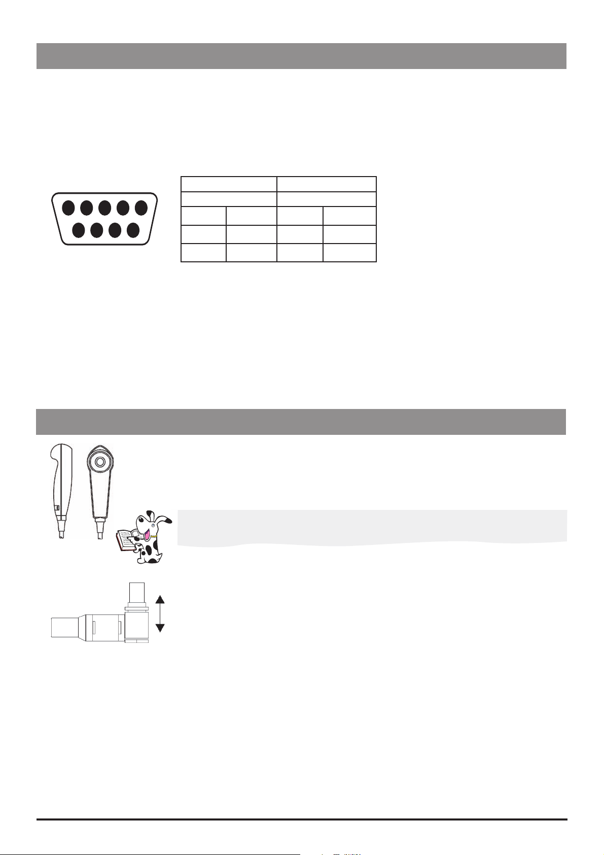
Patient Hand Set
The electronic patient hand set is designed to be ambidextrous and suitable for both adult and paediatric use.
The indicator light can be configured to show when the PCA dose is available or being delivered. Should the clinical
situation require it, the indicator light can be disabled. The PCA button will provide feed-back on all, or just good
demands. See Chapter 2, 'General Options' for HANDSET MODE configuration details.
The patient handset does not contain any latex.
The hand set connector is a latching (but non-locking) connector. To remove, hold the body of the
connector and pull away from the pump. If required, the pump can be operated in continuous or
clinician over-ride modes without the hand set connected.
Note: An alarm warning will operate if the hand set is disconnected from the pump while it is in
operation, or when the handset is connected to the pump with the PCA button depressed.
IVAC® PCAM® Syringe Pump 12/106 1000SM00017 Issue 2

Chapter 2
Configuration & Calibration
In this chapter
Access Codes 14
Entering an Access Code 14
Configuration Options (251) 15
Drug Names and Safety Limits Set Up (251) 16
General Options (251) 17
Preset Protocol Set Up (251) 19
Syringe Range Selection (359) 20
Language Selection (359) 20
Setting the End of Infusion (EOI) Position 21
Calibration Procedures 22
Syringe Size Calibration (243) 22
Occlusion Calibration (717) 23
Battery Charge Circuit Verification 25
Clearing Internal RAM (611) 25

Configuration & Calibration
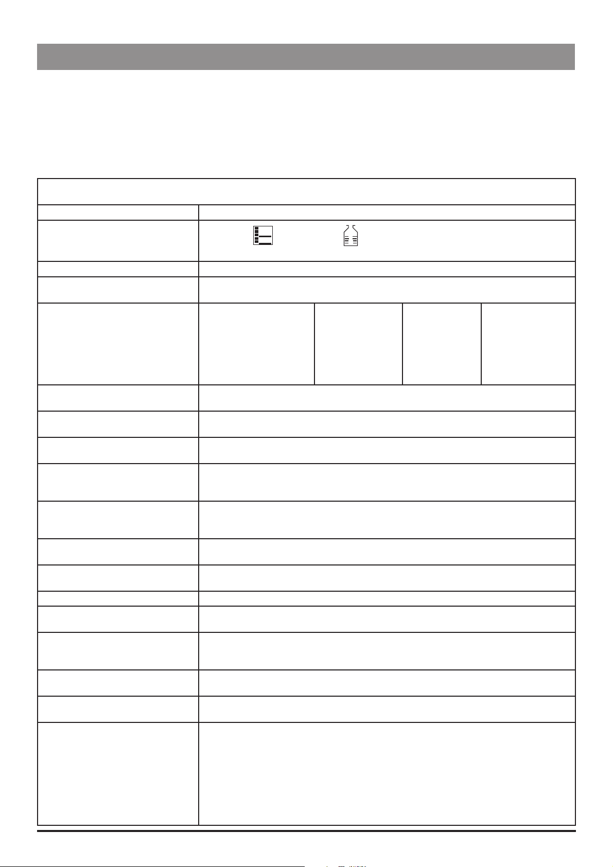
Access Codes
The syringe pump software contains a number of configuration and test routines that can be accessed using a technical access code as
shown in the table below.
Code Title Description
111* HOSPITAL NAME Configure name of hospital/ward to be displayed when pump is powered on and
when pump is in 'sleep' mode (when DISPLAY SLEEP is enabled).
To set the hospital name, use the
S button to adjust, then select OK to store.
the
123 SELF TEST Self test routine begins from the start. See Chapter 3, 'Routine Maintenance' for
further information.
124 SELF TEST Self test routine begins at internal PSU voltage test.
125 SELF TEST Self test routine begins at display test.
126 SELF TEST Self test routine begins at declutch test.
127 SELF TEST Self test routine begins at handset test.
167 COMMS LEARN MODE Configuration set via comms interface.
R Q buttons to toggle through characters and
168 COMMS TEACH MODE Configuration output to another device (pump).
243 SYRINGE SIZE CALIBRATION Syringe size measurement calibration. See 'Calibration Procedures' on the following
pages for instructions.
251 CONFIGURATION OPTIONS
MENU
359 BUILD CONFIGURATION Configure language and syringe range.
376 SERVICE LOG Review and clear service log errors, hours of battery use and hours of pump on
501** MASS DOSING Enable mass dosing. Drugs and protocols use mass dose mode.
502** VOLUME DOSING Enable volume dosing. Drugs and protocols use a mix of mass and volume.
611 TOTAL MEMORY CLEAR Reset memory. Note that the pump will require full calibration.
717 OCCLUSION CALIBRATION Occlusion calibration. See 'Calibration Procedures' on the following pages for
794 FULL EVENT LOG Enable access to full Event Log.
835 MODIFY CLINICIAN CODE Change the 3-digit clinician over-ride code.
***This option is not available on pumps with software version V2R8 and below.
These options are no longer in use on pumps with software version V3R2 and above. See DOSE MODE in 'Drugs and Safety
Limits' and MIX MASS & VOL MODES in 'General Options (251)'.
Configuration of drug limits, options, protocols and real-time clock. See
'Configuration Options (251)' on the following pages for further details.
time. To reset the service log to zero press the RESET softkey.
instructions.
Entering an Access Code
Each menu (and certain individual options) has its own three-digit technical access code which is entered using the following
procedure:
1. Hold down the
2. When the display shows ACCESS CODE 0 0 0, release the H button.
3. Enter the required access code "XXX" using the
move through the digits).
4. When the required code is shown, select the ENTER option to confirm.
IVAC® PCAM® Syringe Pump 14/106 1000SM00017 Issue 2
H button and switch LOCK 1 to the SET position.
R Q buttons in conjunction with the S button (to select the NEXT option to

Configuration & Calibration
Configuration Options (251)
Enter the access code 251 (see 'Entering an Access Code' on the previous page for instructions). The CONFIGURATION OPTIONS menu
is displayed:
CONFIGURATION OPTIONS MENU
Option Description
DRUG NAMES AND SAFETY LIMITS Set drug names and limits. See the next section for further details.
GENERAL OPTIONS See 'General Options (251)' for further details.
PROTOCOL DEFAULT SET-UP Set default protocol and alter preset protocols. See 'Preset Protocol Set Up' for further
details.
CLOCK SET Set the internal clock.
To set the clock, use the
store.
The internal clock is the reference against which patient history and
events are stored. Patient history should always be recorded and if
required, printed prior to changing the clock.
Changing the clock will automatically:
Reset the time and date against which all new patient history is
Clear previous patient data. Only NEW PATIENT? YES will be
R Q buttons and the S button to adjust, then select OK to
stored and may affect the presentation of the history graphs.
available at start up.
IVAC® PCAM® Syringe Pump 15/106 1000SM00017 Issue 2

Configuration & Calibration
Drug Names and Safety Limits Set Up (251)
1. Enter the access code 251 to display the CONFIGURATION OPTIONS menu.
2. Select DRUG NAMES AND SAFETY LIMITS using the
3. Select NEXT DRUG to choose another drug or select MODIFY DRUG to modify the current drug, as detailed below. Alternatively,
select QUIT to return to the CONFIGURATION OPTIONS menu.
4. Step through each DRUG option (see table below) and modify as required.
Use the R Q buttons to toggle/select a value then select OK to confirm and continue to the next option.
Use the S button at any time to go back to the previous option.
5. When set up is complete, switch LOCK 1 to the OFF position.
DRUG option Description
DRUG NAME Enter drug name.
Use the R Q buttons in conjunction with the S button (to go to the next drug
name letter).
DOSE MODE* Select the dose mode:
VOLUME Volume mode. Drugs and protocols use volume based units. Not
MASS Mass mode. Drugs and protocols use mass based units only.
MINIMUM: DRUG CONC. Set the minimum drug concentration between 1 μg/ml and 999 μg/ml or 1.0 mg/ml
and 99.9 mg/ml. OFF is also available in Volume mode.
R Q buttons then select ENTER. DRUG 1 is displayed.
DRUG NAMES AND SAFETY LIMITS
available when MIX MASS & VOL MODES is disabled.
MAXIMUM: DRUG CONC. Set the maximum drug concentration between 1 μg/ml and 999 μg/ml or 1.0 mg/
ml and 99.9 mg/ml. Maximum value cannot be set below the minimum value.
MINIMUM: LOCKOUT PERIOD Set the minimum lockout period (0 - 180 minutes).
MAXIMUM: LOCKOUT PERIOD Set the maximum lockout period (0 - 180 minutes). Maximum period cannot be set
below minimum period.
MINIMUM: PCA DOSE Set the minimum PCA dose. In Mass mode - between 0 μg and 999 μg or 1.0 mg
and 99.9 mg. In Volume mode, between 0.0 ml and 99.9 ml.
MAXIMUM: PCA DOSE Set the maximum PCA dose. In Mass mode between 0 μg and 999 μg or 1.0 mg and
99.9 mg. Volume mode between 0.0 ml and 99.9 ml.
MAXIMUM: CONTINUOUS Set the maximum continuous dose. In Mass mode - between 0 μg/h and 999 μg/h
or 1.0 mg/h and 99.9 mg/h. In Volume mode - between 0.1 ml/h and 25.0 ml/h
(V2R8 or below), between 0.1 ml/h and 35.0 ml/h (V3R2 or above and for syringes
>50ml).
MAXIMUM: LOADING DOSE Set the maximum loading dose. In Mass mode - between 0 μg and 999 μg or 1.0
mg and 99.9 mg. In Volume mode - between 0.0 ml and 99.9 ml.
MAXIMUM: MAX LIMIT Set the maximum limit. In Mass mode - between 0 μg and 999 μg or 1.0 mg and
999 mg. In Volume mode - between 0.0 ml and 999 ml.
MAXIMUM: CLINICIAN BOLUS Set the maximum clinician bolus dose. In Mass mode - between 1 μg and 999 μg or
1.0 mg and 99.9 mg. In Volume mode - between 0.1 ml and 99.9 ml.
* This option is not available on pumps with software version V2R8 and below.
Note: For pumps with software version V2R8 or earlier, the options may vary, or will not be available. Refer to the
relevant DFU for comprehensive information.
IVAC® PCAM® Syringe Pump 16/106 1000SM00017 Issue 2
Configuration & Calibration
General Options (251)
1. Enter the access code 251 to display the CONFIGURATION OPTIONS menu.
2. Select GENERAL OPTIONS using the
R Q buttons then select ENTER.
3. Use the R Q buttons to toggle/alter a value then select NEXT to move to the next option. Select QUIT at any time to go back to
GENERAL OPTIONS menu.
4. When set up is complete, switch LOCK 1 to the OFF position.
GENERAL OPTIONS
Software version: V3R2
Option Description
1. ICONS ON DISPLAY
YES:
The
NO:
No icons are shown on the Display.
(Pressure) and
H
(Max dose) icons are shown on the Display.
2. PROTOCOLS IN USE Set the number of preset protocols to be available (1 to 10).
3. MODIFY PROTOCOL YES:
NO:
4. HANDSET MODE MODE
BEEP
Allows protocols to be modified in SET mode.
MODIFY PROTOCOL option disabled (removed from SET mode).
A
GOOD
ALL
B
ALL
C
Handset light:
PCA STOPPED
PCA AVAILABLE
PCA DELIVERING
PCA LOCKOUT
5. DELAYED CALL BACK YES:
NO:
6. DISPLAY SLEEP YES:
NO:
7. CHIRP LOW ALARMS YES:
NO:
8. CONTINUOUS INFUSIONS YES:
NO:
Call-back alarm can be delayed (10 - 90 minutes).
Call-back will be cancelled (up to 2 minutes, or extended to 15 minutes).
During operation, Display goes blank (into sleep mode) after 2 minutes.
Display stays on during operation.
"Chirp" alarm occurs during use of battery/near end of battery.
No "chirp" alarm during use of battery/near end of battery.
CONTINUOUS infusion option enabled in PROTOCOL set up.
Continuous infusions are not available. Option not available in PROTOCOL set
OFF
ON
FLASH
OFF
ON
ON
ON
ON
OFF
ON
FLASH
ON
up.
9. LOADING DOSES YES:
LOADING DOSE option enabled in PROTOCOL set up. To activate this option,
NEW PATIENT is confirmed. Start the PCA.
NO:
10. MAX DOSE LIMITS YES:
NO:
11. VARIABLE DOSE RATES YES:
NO:
Loading doses are not available.
MAX LIMIT option enabled in PROTOCOL set up.
Dose limits are not available. Option not available in PROTOCOL set up.
PCA DELIVERY option enabled in PROTOCOL set up
Variable PCA doses not available.
12. COMMS PUMP IDENTITY Set pump identity for use with remote communications (000 to 127).
13. COMMS ENABLED YES:
NO:
14. NURSE CALL YES:
RS232 communications enabled.
RS232 communications disabled.
Nurse Call feature enabled (hardware feature allowing pump to communicate
with the hospital's nurse call system, typically linked to central nurse's station).
NO:
15. NURSE CALL INVERTED YES:
NO:
16. CONTINUOUS PRINT YES:
NO:
Nurse Call feature disabled.
Nurse call hardware output is inverted.
Nurse call hardware output normal.
Enables printing of events as they occur.
Continuous printing disabled.
17. DEFAULT SYRINGE Set default syringe type:
BD PLASTIPAK
IVAC
TERUMO
B. BRAUN OMNIFIX
MONOJECT
R.R PRONTO
BD WORLDWIDE
ONCE
FRESENIOUS INJECT.
RAPIJECT
PHARMA-JECT
BD PRECISE
BRAUN PERFUSOR*
JANPOL*
* with options kit fitted
IVAC® PCAM® Syringe Pump 17/106 1000SM00017 Issue 2

Configuration & Calibration
General Options (251) continued
GENERAL OPTIONS (continued)
Software version: V3R2
Option Description
18. LOCK SYRINGE TYPE YES:
NO:
19. QUIET MODE YES:
NO:
20. GENERIC DRUG ENABLED YES:
NO:
21. MAX DOSE LIMIT ALARM YES:
NO:
22. MIX MASS & VOL MODES YES:
NO:
Notes:
1) For pumps with software version V2R8 or earlier, the options may vary, or will not be available. Refer to the relevant DFU for
comprehensive information.
2) For default settings, refer to Appendix C, 'Configured Options and Drug Protocol Records'.
Syringe type locked to default syringe type (as set in previous option).
Syringe type not locked to default syringe type - can be changed.
Pump in quiet mode.
Pump in normal mode.
Generic drug (indicated by
protocols. See 'Preset Protocol Set Up' for further details.
Generic drug is not available.
Pump alarms when the maximum dose limit is exceeded.
Pump does not alarm when the maximum dose limit is exceeded.
Drugs can be set in either Mass mode or Volume mode.
All drugs and protocols are in Mass mode only.
XXX DRUG ) is available when modifying
IVAC® PCAM® Syringe Pump 18/106 1000SM00017 Issue 2

Configuration & Calibration
Preset Protocol Set Up (251)
The number of protocols available for use is configured in GENERAL OPTIONS.
1. Enter the access code 251 to display the CONFIGURATION OPTIONS menu.
2. Select PROTOCOL DEFAULT SET-UP using the
3. Select NEXT PROTOCOL to choose another protocol or select MODIFY PROTOCOL to modify the current protocol, as detailed
below. Alternatively, select QUIT to return to the CONFIGURATION OPTIONS menu.
4. Use the
To enter a parameter, highlight it and select ALTER. Where relevant, the limits set in DRUG NAMES AND SAFETY LIMITS are
Use the R Q buttons to toggle/select a value then select OK to confirm. Alternatively, use CANCEL to quit.
Select OK at any time to return to PROTOCOL DEFAULT.
5. When set up is complete, switch LOCK 1 to the OFF position.
R Q buttons to move up/down the list of parameters (see table below).
displayed.
PROTOCOL parameter Description
DRUG NAME
Select the drug. Use the
set up in DRUG NAMES AND SAFETY LIMITS).
If enabled, a generic drug is available, indicated by MASS DRUG or VOL DRUG
(only available when MIX MASS & VOL MODES option is enabled).
Important: The parameter limits of the generic drug are automatically set to the maximum
value.
R Q buttons then select ENTER. PROTOCOL DEFAULT A is displayed.
PROTOCOL DEFAULT SET-UP
R Q buttons to step through the names of the available drugs (as
DRUG CONC. Set the drug concentration between the minimum/maximum limits set for the selected drug.
PCA DOSE Set the PCA dose between the minimum/maximum limits set for the selected drug.
LOCKOUT PERIOD Set the lockout period between the minimum/maximum limits set for the selected drug.
OCCLUSION LEVEL Set the occlusion level (L0 to L10).
CONTINUOUS* Set the continuous rate, below the maximum continuous rate limit set for the selected drug,
or 35ml/h (for syringes >50ml), 20ml/h (for syringes <50 ml and all syringes on pumps with
V2R8 or below), whichever is lowest.
LOADING DOSE* Set the loading dose, below the maximum loading dose set for the selected drug.
MAX LIMIT* Set maximum dose, below the maximum max dose set for the selected drug.
LIMIT DURATION* Set the maximum cumulative period (1 to 8 hours).
PCA DELIVERY* Set the PCA delivery rate. STAT rate 100 ml/h (80 ml/h for 20 ml syringes), or set by delivery
time (1 to 60 minutes).
* These options are not available if disabled.
Note: For pumps with software version V2R8 or earlier, the options may vary, or will not be available. Refer to the
relevant DFU for comprehensive information.
IVAC® PCAM® Syringe Pump 19/106 1000SM00017 Issue 2

Configuration & Calibration
Syringe Range Selection (359)
Configure the pump to use one of the three standard disposable syringe ranges, as listed in the table below.
Ensure that the required options kit is fitted to the pump before selecting the syringe range.
1. Enter the access code 359. See 'Entering an Access Code' for instructions. The display will show the current syringe range.
2. Use the
Syringe Range Syringe Types Size (ml)
UNIVERSAL BD PLASTIPAK 20, 30, 50
IVAC 50, 100
TERUMO 20, 30, 50
BRAUN OMNIFIX 20, 30, 50
MONOJECT 20, 30, 50
RR PRONTO 20, 30, 50
BD WORLDWIDE 20, 30, 50
ONCE 50
FRESENIUS INJECT. 50
RAPIJECT 50
PHARMA-JECT 50
BD PRECISE 20, 50
BRAUN PERFUSOR B BRAUN PERFUSOR 50
JANPOL JANPOL 50
3. Turn LOCK 1 to OFF to complete the configuration.
R Q buttons to select the required syringe range:
Language Selection (359)
Configure the pump's language used for messages shown on display.
1. Enter the access code 359. See 'Entering an Access Code' for instructions. The display will show the current syringe range.
2. Press NEXT to go to language selection.
3. Use the
4. Turn LOCK 1 to OFF to complete the configuration.
R Q buttons to select the required language:
IVAC® PCAM® Syringe Pump 20/106 1000SM00017 Issue 2

Configuration & Calibration
Setting the End of Infusion (EOI) Position
Use the following procedure to check and to set the EOI point.
1. Enter the access code 126 (see 'Entering an Access Code' for instructions).
2. Select NEXT to step through the self-test routines until the display reads EOI opto: x (where x is the current status of the EOI
detector).
3. Move the plunger holder to the right. The display will read EOI opto: 0
4. Load an empty 50ml syringe (see list of suitable syringes below), squeeze the finger grips and move the plunger holder slowly to
the left.
5. Check the display switches from 0 to 1. The position at which the display changes is the EOI point and it depends on the type of
syringe in use. Use the following table to check the EOI point:
Syringe Type Syringe Size (ml) EOI Point (ml)
BD Plastipak 50 5.5
IVAC 50 6.0
Terumo (US manufactured) 50 6.0
Braun Omnifix 50 5.0
Monoject 50 5.5
R.R Pronto 50 7.5
Rapiject 50 3.0
BD Worldwide 50 6.5
Once 50 4.5
Fresenius Inject 50 5.0
Braun Perfusor 50 3.0
Janpol 50 3.0
6. If necessary, separate the lower and upper case of the pump (see Chapter 6, 'Spare Parts Replacement Procedures') and adjust the
position of the EOI actuator on the bottom of the carriage to the desired position, so that the EOI status changes from 0 to 1 at the
position set out in table above.
7. Move the plunger holder and observe that the display changes from 0 to 1 as the syringe passes the EOI position.
If it does not repeat procedure from Step 3.
8. Fit and fasten the case halves together and check the EOI point again.
IVAC® PCAM® Syringe Pump 21/106 1000SM00017 Issue 2
Configuration & Calibration
Calibration Procedures
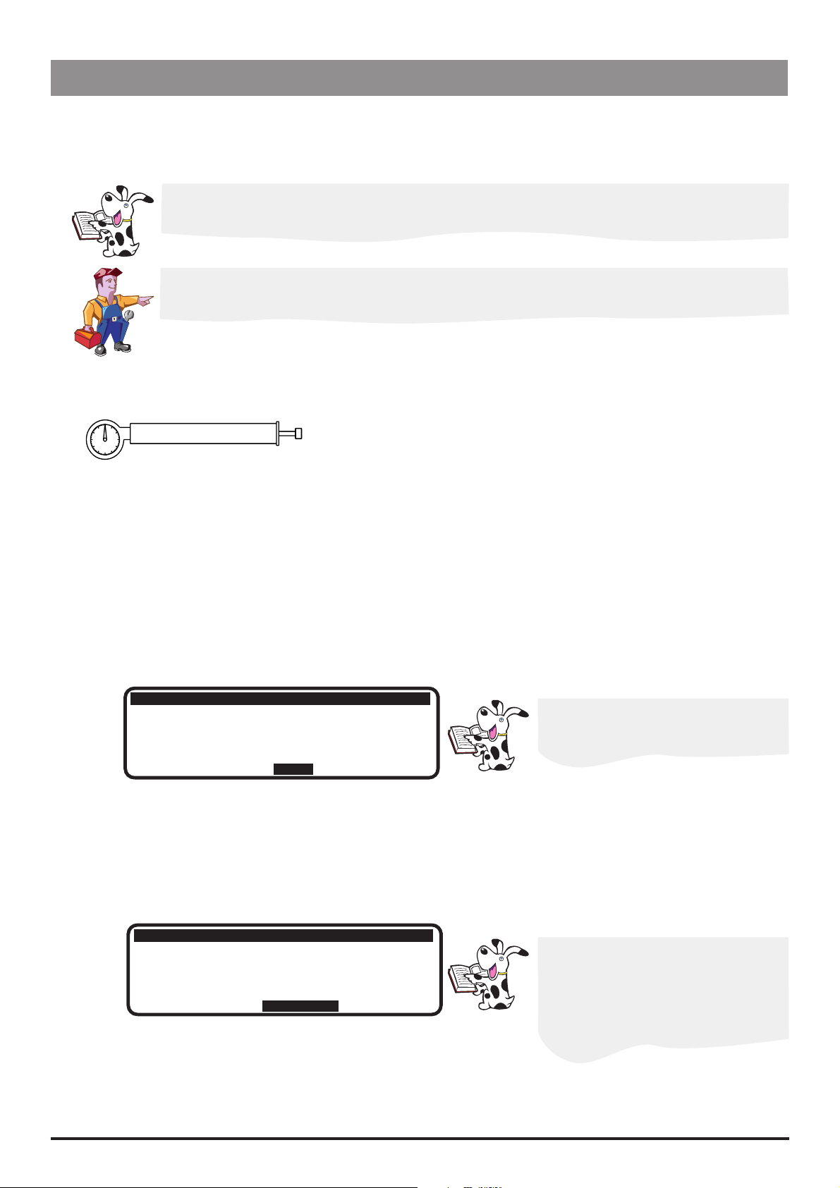
Syringe Size Calibration (243)
To calibrate the syringe size detection system, follow the two-point calibration procedure described below.
Calibration tools required:
1000TG00055 (Syringe Sizing Spacer)
Calibration procedure:
Enter the access code 243.
Fit calibration tool into position on the pump and close the clamp, following Steps 1 - 3 below.
At each step, CALIBRATE is displayed if value is within tolerances.
Select CALIBRATE to store calibration point. Select NEXT to continue to the next screen.
Notes:
1) If CALIBRATE is not displayed, check for correct positioning of calibration tool. If calibration cannot be performed, repairs to
pump may be necessary.
2) The calibration values shown below are for illustrative purposes only.
1000TG00055
Step 1:
Step 2:
Position the narrow end of the calibration
tool under the syringe clamp
Re-position the calibration tool with the
wide end under the syringe clamp
243
243
243
SYRINGE CALIBRATION
Clamp down
SYRINGE CALIBRATION
Clamp down
SYRINGE CALIBRATION
Clamp down
Fit spacer
(40.. 070) : 060
CALIBRATE
(40.. 070) : 060
NEXT
(40.. 070) : 060
(170.. 210) : 186
CALIBRATE
243
SYRINGE CALIBRATION
Clamp down
Fit spacer
Difference
(40.. 070) : 060
(170.. 210) : 186
126
Step 3: Complete calibration
Switch LOCK 1 to the OFF position to complete the
calibration sequence.
Confirmatory Check - To confirm that the syringe sizing calibration has been performed correctly,
select a syringe (preferably 50ml), load and confirm the correct syringe type. Verify that the correct
syringe size is detected and displayed.
IVAC® PCAM® Syringe Pump 22/106 1000SM00017 Issue 2
Configuration & Calibration
Calibration Procedures (continued)
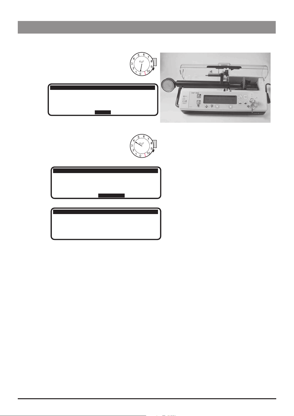
Occlusion Calibration (717)
To set the pump occlusion alarm level, follow the calibration procedure described below. To test the occlusion alarm levels, see
'Occlusion Alarm Levels Test' in Chapter 3.
To convert Kilograms of Force (KgF) to Newtons (N) multiply by 9.806650. For example 10 KgF =
98.07N.
Excessive force will damage the plunger mechanism. Do not apply more than 10 KgF ±0.05
KgF to the plunger mechanism at any time.
Calibration tools required:
0000TG00020 (shown) or 0000TG00200 and 0000JG00014
Calibration procedure:
Enter the access code 717.
Select the OK option to start the drive, following Steps 1-5 below.
Notes:
1) If CALIBRATE does not appear in display, check for correct positioning of tool. If calibration cannot be performed, repairs to the
pump may be necessary.
2) The calibration values shown on the pump displays are for illustrative purposes only.
Step 1: Start drive (without calibration tool fitted)
717
PRESSURE CALIBRATION
Base level 0kgf
(-020.. +020) :
+006
Allow drive to run for approximately
30 seconds to enable the zero pressure
level to settle.
OK
Step 2: Base level
Check pressure reading is within the range displayed.
717
PRESSURE CALIBRATION
Base level 0kgf
(-020.. +020) :
+000
If necessary, open up the pump and
adjust pot RV1 on the Control PCB
until it falls within the range
CALIBRATE
IVAC® PCAM® Syringe Pump 23/106 1000SM00017 Issue 2
Strive for a pressure reading as
close as possible to +000
Configuration & Calibration
Calibration Procedures (continued)
Occlusion Calibration (717) continued
Step 3: Fit calibration tools (0KgF)
717
PRESSURE CALIBRATION
Base level 0kgf
Step 4: Test gear 4.0 KgF
Allow pump to run until the dial gauge
on the test gear reads 4Kgf.
717
Base level 0kgf
Test gear 4.0kgf
717
Base level 0kgf
Test gear 4.0kgf
Difference 0 kgf
(-020.. +020) :
NEXT
PRESSURE CALIBRATION
(-020.. +020) :
(+050.. +100) :
CALIBRATE
PRESSURE CALIBRATION
(-020.. +020) :
(+050.. +100) :
to 4.0 kgf :
+000
+000
+062
+000
+062
+062
Step 5: Complete calibration
Switch LOCK 1 to the OFF position to complete
the calibration sequence.
IVAC® PCAM® Syringe Pump 24/106 1000SM00017 Issue 2

Configuration & Calibration
Battery Charge Circuit Verification
Replacement Power Supply PCBs are supplied with the charging voltage set to the correct value. The procedure below can be followed
in order to check the DC voltage setting if deemed necessary.
Equipment required: Oscilloscope
1. Ensure that the pump is swtiched OFF and is disconnected from the AC power supply.
2. Access the pump, see Chapter 6, 'Spare Parts Replacement Procedures' for instructions.
3. Disconnect the battery connector from the Power Supply PCB and connect the oscilloscope to PL3 (0V to pin 1).
4. Set the oscilloscope range to 0 to 7 VDC.
5. Connect the pump to AC power supply.
6. Adjust RV1 on the Power Supply PCB until the peak voltage level displayed on the oscilloscope is 7.0 ± 0.1 VDC.
7. Reseal RV1.
8. Disconnect the AC power supply, remove the oscilloscope connections and refit the battery connector.
Clearing Internal RAM (611)
Warning: Do not clear the RAM unless absolutely necessary because all the calibration and
configuration in the pump will be cleared.
If the internal RAM or its associated battery is replaced on the Control PCB, or if the pump fails with a 'CODE 5' RAM error it will be
necessary to do the following:
Clear the internal RAM:
1. Enter the access code 611.
2. Select ENTER and wait for the RAM to be cleared.
3. When the message RAM CLEARED appears, switch LOCK 1 to the OFF position.
Fully calibrate pump. Perform each of the two calibration procedures, as described in this chapter.
Reconfigure the pump:
Set Configuration, Drugs and Safety Limits and Protocols (it may be possible to use the Teach/Learn facility, see Chapter 3,
'Routine Maintenance' for instructions)
Enter the access code 359 and set syringe range and language
Enter the access code 376 and set service date
Carry out Performance Verification Procedure (PVP). See Chapter 3, 'Routine Maintenance' for instructions.
IVAC® PCAM® Syringe Pump 25/106 1000SM00017 Issue 2

Routine Maintenance
In this chapter
Introduction 27
Chapter 3
Self-Test Procedure (123) 27
Upgrading Software 28
Event Log Download 29
Teach Learn 31
Linear Speed Test 32
Syringe Constant Values 33
Occlusion Test 34
Potential Equalisation Terminal Resistance Test (PE Test) 35
Battery Maintenance 36
Physical Inspection and Clean 36
Performance Verification Procedure 37

Routine Maintenance
Introduction
For routine maintenance, the following tests and performance verification procedure should be performed in addition to the tasks
described in the section 'Physical Inspection and Clean'.
Refer to the relevant DFU for the recommended routine maintenance period.
Self-Test Procedure (123)
The self-test procedure is designed to allow confirmation of many of the pump functions, defaults and calibrations without requiring
internal inspection.
1. Enter the access code 123. See 'Entering an Access Code' in Chapter 2 for instructions.
2. The pump now proceeds through a series of tests. Press the NEXT softkey to move to the next test.
Refer to the table below for details of each test.
Important: If the pump fails the test sequence at any stage, it should be taken out of service and inspected by a qualified service
engineer.
Test Display Description/Action
Review software setup Software revision
Program CRC
Language
Hospital name
Displays software version, program CRC, language and hospital name.
Review syringe data Syr range
Syr cal
Occ cal
Internal PSU voltage Internal PSU voltage:
_ . _ _ V
Audible: Alarm Audible alarm Check that the alarm sounds continuously.
Visual: Display and
Backlight
Touch panel buttons Press S1 Press buttons in turn from START (01) to PURGE (10).
Display test
Backlight
Displays syringe range, syringe and occlusion calibration figures.
On mains supply: 9.00V approximately
On battery supply: 5.20V - 6.50V
Check that the display dots are an even tone as they all go on full
backlight, then to dim, then turn off.
H 01 S 06
I 02 J 07
R 03 V 08
Q 04 G 09
S 05 T 10
Visual: LED Indicators LEDS flashing Check that the STOP and START LED’S are flashing.
Declutch switch Declutch: Squeeze plunger holder finger grips and check that the display
alternates between 1 (engaged) and 0 (disengaged - finger grips
squeezed together).
Near End of Infusion EOI opto: Starting with an empty, extended 50ml syringe on the pump, squeeze
the finger grips and move the plunger holder slowly to the left. Check the
display switches from 0 to 1. The position at which the display changes (EOI
point) depends on the type of syringe in use. See 'Setting the EOI Position' in
Chapter 2. for values.
Linear Grid Grid opto: Squeeze the plunger holder grips together and slide the mechanism
to the right. Slowly move the syringe plunger to the left and check the
display alternates between 0 (OPTO over slot) and 1 (OPTO over bar).
Plunger Detector Plunger opto: Press plunger plate button. Check the display switches from 1 (no syringe
plunger fitted) to 0 (syringe plunger fitted).
Motor Encoder Motor/encoders: Motor is pulsed while encoders are tested. Motor moves forwards and
backwards as encoders pass.
Cover Detect Cover detect: Open and close the cover. Check that the display changes from 0 (cover
open) to 1 (cover closed).
IVAC® PCAM® Syringe Pump 27/106 1000SM00017 Issue 2
Routine Maintenance
Self-Test Procedure (123) continued
Test Display Description/Action
Syringe Size Detection Syringe pot: Lift the syringe clamp and check that the values displayed increase
within the normal range (approx. 045 to 215).
Pumping Pressure
Detection
Patient Handset Handset: Connect handset and check that the display changes from OFF to ON
Key Switch Key switch: Turn key from SET position to RUN position and the check the display
Nursecall Nurse call on/off/on Check for audible clicks of the relay.
Beam value: Remove the syringe and confirm that the value displayed is within
normal range (-020 to +020). Gently press back on the plunger holder
and watch the value increase.
when the button is pressed. Also check that the handset LED lights up
then goes off.
changes accordingly.
Configuration summary Summary of configured
options
Select the NEXT option and scroll to the next page of configured
options, then to normal operation.
Upgrading Software
Upgrade of the IVAC® PCAM Syringe Pump software to V2R8 or greater is recommended when
serviced.
Perform upgrades by acquiring the software upgrade kits specified in spare parts listings.
Equipment required: Software upgrade kit (includes EPROM fitting and removal instructions)
Software Upgrade Kits Available
Part Number Description
5000SP00049 V3R2 software + DFU English/French/German
5000SP00053 V3R2 software + DFU English/French/Dutch
5000SP00054 V3R2 software + DFU English/Spanish
5000SP00055 V3R2 software + DFU English/Italian/German
5000SP00056 V3R2 software + DFU English/Swedish
IVAC® PCAM® Syringe Pump 28/106 1000SM00017 Issue 2
Routine Maintenance
Event Log Download
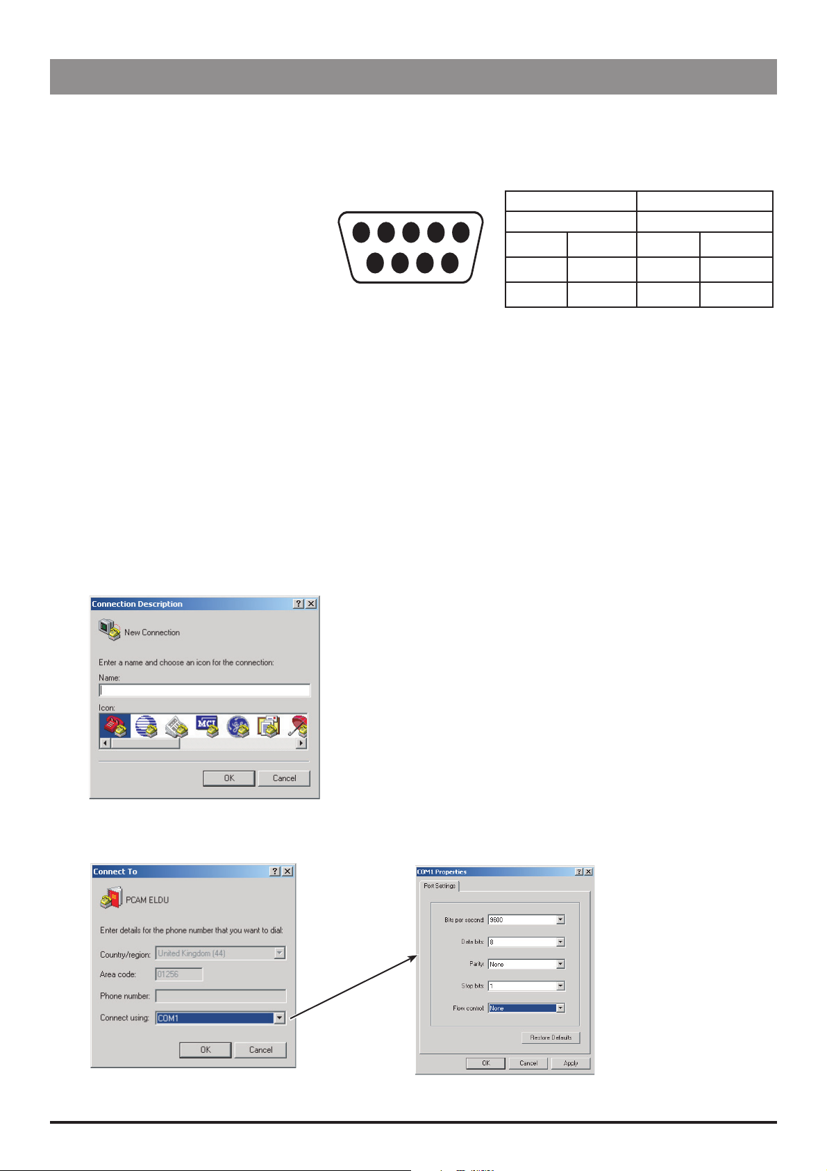
The Event Log can be downloaded directly to a PC using Microsoft HyperTerminal.
Note: The procedure below uses Microsoft HyperTerminal - Microsoft Windows XP Professional.
Equipment required:
RS232 cable, 9-pin D type
PC running Microsoft Windows
Cabling connections:
GND PWR1 TXD2 RXD2 ALM IN
5 4 3 2 15 4 3 2 1
6 7 8 9
NC NC CTS1 TXD1
Pump PC
Male Female
Pin 5
Pin 8
Pin 9
GND Pin 5 GND
CTS1 Pin 4 PWR1
TXD1 Pin 2 RXD2
Pump Set Up
1. Connect the RS232 cable to the serial port of the pump and the COM port of the PC.
2. Enter access code 794. See 'Entering an Access Code' in Chapter 2 for instructions. This enables access to the full Event Log.
3. Turn the pump OFF.
4. Turn the pump ON. Select NO to retain previous patient data.
5. Press the
to be downloaded.
J button four times to display the Event Log. Use the R Q buttons to position the cursor at the start point of events
Set Up HyperTerminal on your PC
1. Open HyperTerminal on your PC. Click Start, point to All Programs, point to Accessories, point to Communications, and then
click HyperTerminal. Enter a HyperTerminal connection name, for example, PCAM ELDU, select an icon and click OK.
2. Select COM1 and click OK (leaving Country/region and Area code as default). Ensure COM1 is not already pre configured, for
example, pre configured for a hand-held PC. Configure COM1 Properties as shown below, click Apply then OK.
IVAC® PCAM® Syringe Pump 29/106 1000SM00017 Issue 2
Routine Maintenance
Event Log Download (continued)
Set Up HyperTerminal on your PC (continued)
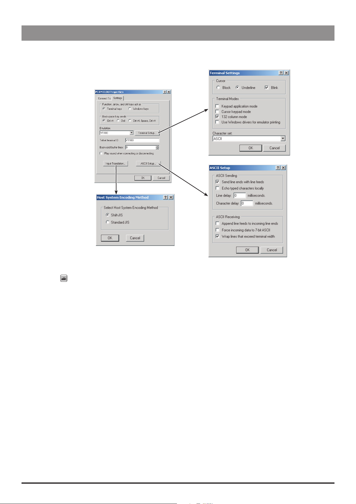
3. On the File menu, select Properties. Select the Settings tab then configure settings as shown below. Click OK to close the
Properties window.
4. On the Transfer menu, select Capture Text. Enter file name and desired location for data to be saved to (example, D:\DATA\PCAM
EVENTLOG). Click Start.
5. Press the
button on the pump.
6. Once finished, the Event Log data will be displayed on the PC screen.
7. Save and Close HyperTerminal.
8. Locate the saved file (example D:\DATA\PCAM EVENTLOG) and open it using Wo rdPad. Save the WordPad document as a unicode
text document:
On the WordPad File menu, select Save As. Enter a File name (i.e. pump serial number). Select file type (Unicode Text Document)
from the drop-down box then click Save.
Example Event Log Download
08/06/04 10:07 ---- POWER ON ---- 0 ug
08/06/04 10:07 NEW PATIENT 0 ug
08/06/04 10:07 PROTOCOL CONFIRMED 0 ug
08/06/04 10:07 DRUG UFTU 1
08/06/04 10:07 DRUG CONC. 1.0 mg/ml
08/06/04 10:07 PCA DOSE 1.0 mg
08/06/04 10:07 LOCKOUT 5 min
08/06/04 10:07 OCCLUSION ALARM 4
08/06/04 10:07 CONTINUOUS 0 ug/h
08/06/04 10:07 DOSE LIMIT 50.0 mg
08/06/04 10:07 LIMIT PERIOD 4 h
08/06/04 10:07 50 ml BD PLASTIPAK
08/06/04 10:07 PCAM START 0 ug
08/06/04 10:07 GOOD DEMAND 0 ug
Example (continued)
08/06/04 10:07 PCAM STOP 90 ug
08/06/04 10:07 PCAM START 90 ug
08/06/04 10:08 LOCKOUT START 1.00 mg
IVAC® PCAM® Syringe Pump 30/106 1000SM00017 Issue 2
 Loading...