


Technical Service Manual
Alaris® PC Unit, Models 8000 and 8015
Alaris® Pump Module, Model 8100
Supports: Guardrails® Suite (v7)
Guardrails® Suite MX (v8)
March 2007
ALARM
I
NFU
S
E
S
TANDBY
SILENCE |
|
SILENCE |
|
SYSTEM |
|
OPTIONS |
ON |
OPTIONS |
1 |
2 |
3 |
|
1 |
2 |
3 |
4 |
5 |
6 |
|
4 |
5 |
6 |
7 |
8 |
9 |
ENTER |
7 |
8 |
9 |
CLEAR |
0 |
. |
CANCEL |
CLEAR |
0 |
|
RATE (mL/h)
CHANNEL
SELECT
PAUSE
SYSTEM
ON CHANNEL
OFF
RESTART
ENTER
CANCEL
Model 8000 |
Model 8015 |
Model 8100 |
Alaris® Products

General Contact Information
Cardinal Health
Alaris® Products 10221 Wateridge Circle
San Diego, California 92121 cardinal.com/alaris
Customer Advocacy - North America
Clinical and technical feedback.
Phone: 800.854.7128, Ext. 7812
E-Mail: CustomerFeedback@cardinal.com
Technical Support - North America
Maintenance and service information support; troubleshooting.
United States: |
Canada: |
Phone: |
Phone: |
858.458.6003 |
Eastern: 800.908.9918 |
800.854.7128, Ext. 6003 |
Western: 800.908.9919 |
Customer Care - North America
Instrument return, service assistance, and order placement.
United States: |
Canada: |
Phone: 800.482.4822 |
Phone: 800.387.8309 |
|
|
Alaris® PC Unit
Alaris® Pump Module
Technical Service Manual

|
TABLE OF CONTENTS |
|
|
|
|
Chapter 1 - General Information |
|
|
1.1 |
Introduction....................................................................................................................................................................................... |
1-1 |
1.2 |
Alarms and Messages............................................................................................................................................................... |
1-2 |
1.3 |
Battery Management System................................................................................................................................................ |
1-2 |
1.3.1 |
Battery and Charging Process............................................................................................................................................. |
1-2 |
1.3.2 |
System On/Off................................................................................................................................................................................ |
1-3 |
1.3.3 |
Real Time Clock (RTC) with NVRam Control Lithium Battery-Backed RTC .......................................... |
1-3 |
1.3.4 |
Battery Maintenance................................................................................................................................................................... |
1-4 |
1.4 |
Battery Capacity Information................................................................................................................................................. |
1-5 |
1.5 |
Pole Clamp Feature..................................................................................................................................................................... |
1-6 |
1.6 |
Memory............................................................................................................................................................................................... |
1-6 |
Chapter 2 - Checkout and Configuration |
|
|
2.1 |
Introduction....................................................................................................................................................................................... |
2-1 |
2.2 |
New Instrument Checkout....................................................................................................................................................... |
2-1 |
2.3 |
Configuration Options and Setup - General ................................................................................................................ |
2-1 |
2.3.1 |
Configuration Notes .................................................................................................................................................................... |
2-1 |
2.3.2 |
Configuration Setup Notes...................................................................................................................................................... |
2-2 |
2.4 |
Configuration Setup - PC Unit .............................................................................................................................................. |
2-2 |
2.4.1 |
Access System Configuration Options ........................................................................................................................... |
2-2 |
2.4.2 |
Alarm audio ...................................................................................................................................................................................... |
2-3 |
2.4.3 |
Anesthesia Mode.......................................................................................................................................................................... |
2-3 |
2.4.4 |
Battery meter................................................................................................................................................................................... |
2-3 |
2.4.5 |
Clock setup....................................................................................................................................................................................... |
2-4 |
2.4.6 |
Key click audio................................................................................................................................................................................ |
2-5 |
2.4.7 |
Max Pt. weight................................................................................................................................................................................ |
2-5 |
2.4.8 |
Patient ID Entry.............................................................................................................................................................................. |
2-6 |
2.4.9 |
PM reminder..................................................................................................................................................................................... |
2-6 |
2.4.10 |
Profiles................................................................................................................................................................................................. |
2-6 |
2.4.11 |
Tamper resist................................................................................................................................................................................... |
2-7 |
2.5 |
Configuration Setup - Pump Module ................................................................................................................................ |
2-7 |
2.5.1 |
Access System Configuration Options ........................................................................................................................... |
2-7 |
2.5.2 |
Accumulated air............................................................................................................................................................................. |
2-8 |
2.5.3 |
Air-in-line settings......................................................................................................................................................................... |
2-8 |
2.5.4 |
Auto-restart attempts ................................................................................................................................................................. |
2-8 |
2.5.5 |
KVO rate adjust.............................................................................................................................................................................. |
2-9 |
2.5.6 |
Max rate.............................................................................................................................................................................................. |
2-10 |
Alaris® PC Unit |
i |
Alaris® Pump Module |
|
Technical Service Manual |
|

TABLE OF CONTENTS
Chapter 2 - Checkout and Configuration (Continued)
2.5.7 |
Max VTBI........................................................................................................................................................................................... |
2-10 |
2.5.8 |
Pressure mode............................................................................................................................................................................... |
2-11 |
2.5.9 |
SEC-PRI alert ................................................................................................................................................................................. |
2-12 |
2.5.10 |
Secondary......................................................................................................................................................................................... |
2-13 |
2.6 |
Configuration Setup - Shared Infusion............................................................................................................................ |
2-13 |
2.6.1 |
Access System Configuration Options ........................................................................................................................... |
2-13 |
2.6.2 |
Delay Options.................................................................................................................................................................................. |
2-13 |
2.6.3 |
Drug Calculation............................................................................................................................................................................ |
2-14 |
2.6.4 |
Multidose............................................................................................................................................................................................ |
2-15 |
2.6.5 |
Pressure dynamic......................................................................................................................................................................... |
2-16 |
2.6.6 |
Volume/Duration............................................................................................................................................................................ |
2-16 |
Chapter 3 - Preventive Maintenance
3.1 |
Introduction....................................................................................................................................................................................... |
3-1 |
3.2 |
Cleaning.............................................................................................................................................................................................. |
3-1 |
Chapter 4 - Principles of Operation
4.1 |
Introduction....................................................................................................................................................................................... |
4-1 |
4.2 |
PC Unit ................................................................................................................................................................................................ |
4-1 |
4.2.1 |
Logic Board Assembly - Model 8000............................................................................................................................... |
4-1 |
4.2.2 |
Logic Board Assembly - Model 8015................................................................................................................................ |
4-3 |
4.2.3 |
Power Supply Board Assembly ........................................................................................................................................... |
4-4 |
4.2.4 |
Power Requirements .................................................................................................................................................................. |
4-5 |
4.2.5 |
Mechanical........................................................................................................................................................................................ |
4-6 |
4.3 |
Pump Module .................................................................................................................................................................................. |
4-7 |
4.3.1 |
Display Board Assembly .......................................................................................................................................................... |
4-8 |
4.3.2 |
Logic Board Assembly............................................................................................................................................................... |
4-9 |
4.3.3 |
Motor Controller Board Assembly...................................................................................................................................... |
4-12 |
4.3.4 |
Mechanical........................................................................................................................................................................................ |
4-12 |
4.4 |
Power Control Circuit ................................................................................................................................................................. |
4-13 |
4.5 |
Inter-Unit Communications Circuit and Connections............................................................................................. |
4-13 |
4.5.1 |
Software ............................................................................................................................................................................................. |
4-14 |
4.5.2 |
Unit Detection and Identification Circuitry..................................................................................................................... |
4-14 |
4.5.3 |
IUI ........................................................................................................................................................................................................... |
4-15 |
4.5.4 |
Module Detection and Logical Designation.................................................................................................................. |
4-16 |
4.5.5 |
Unit ID Assignment at System On ..................................................................................................................................... |
4-16 |
4.5.6 |
Module Attachment After System On .............................................................................................................................. |
4-18 |
ii |
Alaris® PC Unit |
|
Alaris® Pump Module |
|
Technical Service Manual |

|
|
TABLE OF CONTENTS |
|
|
|
Chapter 4 - Principles of Operation (Continued) |
|
|
4.5.7 |
Module Detachment.................................................................................................................................................................... |
4-18 |
4.5.8 |
Communications Time-Out .................................................................................................................................................... |
4-18 |
Chapter 5 - Corrective Maintenance |
|
|
5.1 |
Introduction....................................................................................................................................................................................... |
5-1 |
5.2 |
Disassembly / Reassembly .................................................................................................................................................... |
5-1 |
5.3 |
PC Unit ................................................................................................................................................................................................ |
5-3 |
5.3.1 |
Battery Pack Assembly............................................................................................................................................................. |
5-3 |
5.3.2 |
Latch Assembly.............................................................................................................................................................................. |
5-4 |
5.3.3 |
Power Cord....................................................................................................................................................................................... |
5-5 |
5.3.4 |
Pole Clamp Assembly................................................................................................................................................................ |
5-6 |
5.3.5 |
Rear Panel (Model 8000) and Rear Panel Assembly............................................................................................ |
5-7 |
5.3.6 |
Rear Panel Assembly Parts................................................................................................................................................... |
5-8 |
5.3.7 |
Model 8000: CI Board Accessory (Model 8012)....................................................................................................... |
5-10 |
5.3.8 |
Model 8015: Wireless Network Card Assembly........................................................................................................ |
5-11 |
5.3.9 |
Model 8000: Nurse Call Accessory (Model 8010)................................................................................................... |
5-13 |
5.3.10 |
Model 8000: Nurse Call / CI Board Accessory.......................................................................................................... |
5-16 |
5.3.11 |
Handle.................................................................................................................................................................................................. |
5-17 |
5.3.12 |
Front and Rear Case Separation........................................................................................................................................ |
5-18 |
5.3.13 |
Model 8000: Display and Retainer .................................................................................................................................... |
5-19 |
5.3.14 |
Model 8015: Display, Retainers, and Inverter Board.............................................................................................. |
5-20 |
5.3.15 |
IUI Connectors................................................................................................................................................................................ |
5-22 |
5.3.16 |
Rear Case Assembly Parts.................................................................................................................................................... |
5-23 |
5.3.17 |
Model 8015: Memory Card..................................................................................................................................................... |
5-25 |
5.3.18 |
Chassis Assembly Parts .......................................................................................................................................................... |
5-26 |
5.4 |
Pump Module .................................................................................................................................................................................. |
5-28 |
5.4.1 |
Latch Assembly and Feet........................................................................................................................................................ |
5-28 |
5.4.2 |
IUI Connectors and Rear Case............................................................................................................................................ |
5-29 |
5.4.3 |
Door/Display Board Assembly.............................................................................................................................................. |
5-30 |
5.4.4 |
Display Board Assembly .......................................................................................................................................................... |
5-31 |
5.4.5 |
Door Latch Assembly................................................................................................................................................................. |
5-32 |
5.4.6 |
Platen Assembly............................................................................................................................................................................ |
5-33 |
5.4.7 |
Logic and Motor Controller Board Assemblies .......................................................................................................... |
5-34 |
5.4.8 |
Motor, Air-in-Line (AIL) Sensor Assembly, and Bezel Assembly.................................................................... |
5-36 |
5.4.9 |
Membrane Frame Assembly and Pressure Sensors ............................................................................................. |
5-38 |
Alaris® PC Unit |
iii |
Alaris® Pump Module |
|
Technical Service Manual |
|

TABLE OF CONTENTS
Chapter 6 - Troubleshooting
6.1 |
Introduction....................................................................................................................................................................................... |
6-1 |
6.2 |
Errors.................................................................................................................................................................................................... |
6-1 |
6.2.1 |
Error Numbering Scheme........................................................................................................................................................ |
6-2 |
6.3 |
Maintenance Mode ...................................................................................................................................................................... |
6-2 |
6.3.1 |
External Communications....................................................................................................................................................... |
6-3 |
6.3.2 |
Calibration Parameters ............................................................................................................................................................. |
6-3 |
6.3.3 |
Clock Setup ...................................................................................................................................................................................... |
6-4 |
6.3.4 |
Battery Conditioning Test ........................................................................................................................................................ |
6-5 |
6.3.5 |
Keypad Test...................................................................................................................................................................................... |
6-6 |
6.3.6 |
Display Test...................................................................................................................................................................................... |
6-6 |
6.3.7 |
Display Error Log .......................................................................................................................................................................... |
6-7 |
6.3.8 |
Display Contrast ............................................................................................................................................................................ |
6-8 |
Chapter 7 - Illustrated Part Breakdown
7.1 |
Introduction....................................................................................................................................................................................... |
7-1 |
7.2 |
Illustrations........................................................................................................................................................................................ |
7-1 |
7.3 |
Parts List ............................................................................................................................................................................................ |
7-1 |
7.4 |
Ordering Parts ................................................................................................................................................................................ |
7-2 |
Figures
4-1 |
Block Diagram - Models 8000 and 8015........................................................................................................................ |
4-20 |
4-2 |
Block Diagram - Model 8100 ................................................................................................................................................. |
4-21 |
7-1 |
Models 8000 and 8015 - Chassis Assembly............................................................................................................... |
7-9 |
7-2 |
Model 8015 - Memory Card ................................................................................................................................................... |
7-10 |
7-3 |
Models 8000 and 8015 - Rear Case Assembly......................................................................................................... |
7-11 |
7-4 |
Models 8000 and 8015 - IUI Connectors and Backup Speaker...................................................................... |
7-13 |
7-5 |
Model 8000 - LED Display Assembly .............................................................................................................................. |
7-14 |
7-6 |
Model 8015 - LED Display Assembly............................................................................................................................... |
7-15 |
7-7 |
Models 8000 and 8015 - Front to Rear Case Assembly...................................................................................... |
7-17 |
7-8 |
Models 8000 and 8015 - Handle Assembly................................................................................................................. |
7-18 |
7-9 |
Models 8000 and 8015 - Rear Panel Assembly........................................................................................................ |
7-19 |
7-10 |
Model 8000 - Rear Plate Assembly .................................................................................................................................. |
7-21 |
7-11 |
Model 8015 - Wireless Network Assembly................................................................................................................... |
7-23 |
7-12 |
Model 8000 - Model 8010 Nurse Call Accessory .................................................................................................... |
7-24 |
7-13 |
Model 8000 - Model 8012 Communications Interface Accessory................................................................. |
7-25 |
7-14 |
Model 8000 - Communications Interface Board / Nurse Call Accessory ................................................. |
7-26 |
7-15 |
Models 8000 and 8015 - Pole Clamp Assembly....................................................................................................... |
7-27 |
iv |
Alaris® PC Unit |
|
Alaris® Pump Module |
|
Technical Service Manual |

|
|
TABLE OF CONTENTS |
|
|
|
Figures (Continued) |
|
|
7-16 |
Models 8000 and 8015 - Power Cord Assembly and Labels............................................................................ |
7-28 |
7-17 |
Models 8000 and 8015 - Latch Assembly..................................................................................................................... |
7-29 |
7-18 |
Models 8000 and 8015 - Battery Pack Assembly.................................................................................................... |
7-30 |
7-19 |
Model 8015 - Communications Board ............................................................................................................................. |
7-31 |
7-20 |
Model 8015 - Inverter Board.................................................................................................................................................. |
7-32 |
7-21 |
Models 8000 and 8015 - Isolated RS-232 Board..................................................................................................... |
7-33 |
7-22 |
Models 8000 and 8015 - IUI Boards................................................................................................................................. |
7-34 |
7-23 |
Model 8000 - Logic Board....................................................................................................................................................... |
7-35 |
7-24 |
Model 8015 - Logic Board ....................................................................................................................................................... |
7-36 |
7-25 |
Models 8000 and 8015 - Power Supply Board .......................................................................................................... |
7-37 |
7-26 |
Model 8100 - Membrane to Bezel Assembly .............................................................................................................. |
7-41 |
7-27 |
Model 8100 - Motor and AIL Sensor Assembly......................................................................................................... |
7-42 |
7-28 |
Model 8100 - Logic Board and Motor Controller Board Assembly................................................................ |
7-43 |
7-29 |
Model 8100 - Platen Assembly ............................................................................................................................................ |
7-44 |
7-30 |
Model 8100 - Door and Display Board Assembly .................................................................................................... |
7-45 |
7-31 |
Model 8100 - Rear Case and IUI Connectors ............................................................................................................ |
7-47 |
7-32 |
Model 8100 - Latch and Feet Assembly......................................................................................................................... |
7-48 |
7-33 |
Model 8100 - Label Locations............................................................................................................................................... |
7-49 |
7-34 |
Model 8100 - AIL Board............................................................................................................................................................ |
7-50 |
7-35 |
Model 8100 - Display Board................................................................................................................................................... |
7-51 |
7-36 |
Model 8100 - Logic Board ....................................................................................................................................................... |
7-52 |
7-37 |
Model 8100 - Motor controller Board................................................................................................................................ |
7-53 |
Tables |
|
|
1-1 |
Defined Terms ................................................................................................................................................................................ |
1-2 |
1-2 |
Battery Trip Points........................................................................................................................................................................ |
1-4 |
1-3 |
Abbreviations, Acronyms, Symbols................................................................................................................................... |
1-7 |
4-1 |
Power Sources............................................................................................................................................................................... |
4-5 |
4-2 |
Power Supply Board Voltages.............................................................................................................................................. |
4-6 |
4-3 |
IUI Logic.............................................................................................................................................................................................. |
4-17 |
4-4 |
IUI Signals......................................................................................................................................................................................... |
4-17 |
5-1 |
Required Materials, Supplies and Tools......................................................................................................................... |
5-2 |
5-2 |
Torque Values - Models 8000 and 8015 ........................................................................................................................ |
5-39 |
5-3 |
Torque Values - Model 8100.................................................................................................................................................. |
5-40 |
5-4 |
Level of Testing Guidelines - Models 8000 and 8015............................................................................................ |
5-41 |
5-5 |
Level of Testing Guidelines - Model 8100 ..................................................................................................................... |
5-42 |
6-1 |
Technical Troubleshooting Guide ....................................................................................................................................... |
6-9 |
Alaris® PC Unit |
v |
Alaris® Pump Module |
|
Technical Service Manual |
|

TABLE OF CONTENTS
List of Tables (Continued)
6-2 |
Subsystem Codes ........................................................................................................................................................................ |
6-18 |
6-3 |
Failure Codes.................................................................................................................................................................................. |
6-19 |
6-4 |
Error Codes...................................................................................................................................................................................... |
6-22 |
7-1 |
Parts List - Models 8000 and 8015 ................................................................................................................................... |
7-3 |
7-2 |
Parts List - Model 8100............................................................................................................................................................. |
7-38 |
vi |
Alaris® PC Unit |
|
Alaris® Pump Module |
|
Technical Service Manual |
1 GENERAL INFORMATION

Chapter 1 – GENERAL INFORMATION
CAUTION |
1.1 |
INTRODUCTION |
To avoid damaging the keypad, do not use sharp objects (such as, pens, pencils) to activate switches.
CAUTION
Any attempt to service this product by anyone other than an authorized Cardinal Health Service Representative, while the product is under warranty, may invalidate the warranty.
This manual describes how to service the PC Unit (Models 8000 and 8015) and Pump Module (Model 8100). It is used in
conjunction with the following Alaris® System documents and software:
•Alaris® System Directions for Use (DFU)
•Maintenance software and user manual
This manual is intended for personnel experienced in analysis, troubleshooting and repair of analog/digital microprocessorbased electronic equipment.
Reference the Alaris® System DFU for a product introduction, detailed setup and operation procedures, definitions (including precaution definitions), specifications, and other information related to the use of the Alaris® System.
If the PC Unit or Pump Module requires service while under warranty, it must be serviced only by Cardinal Health
authorized service personnel. Reference the "Warranty" and "Service Information" sections in the Alaris® System DFU.
Important: The SYSTEM ON key becomes the "Power Off" key anytime the Alaris® System is in a watchdog state. The watchdog state is identified by:
•constant loud audio tone that cannot be silenced
•nonresponsive keypad
•flashing red arrow above SYSTEM ON key
Alaris® PC Unit |
1-1 |
Alaris® Pump Module
Technical Service Manual
GENERAL INFORMATION
Table 1-1. Defined Terms
The following table identifies the defined terms used throughout this document for certain trademarked products and product features.
Product / Feature |
|
|
Defined Term |
|||
Alaris® Auto-ID module |
Auto-ID Module |
|||||
Alaris® EtCO |
2 |
module |
EtCO |
2 |
Module |
|
|
|
|
|
|
||
Alaris® PCA module |
PCA Module |
|||||
Alaris® PC point-of-care unit |
PC Unit |
|||||
Alaris® PC unit |
PC Unit |
|||||
Alaris® Pump module |
Pump Module |
|||||
Alaris® SpO |
module |
SpO |
2 |
Module |
||
2 |
|
|
|
|
|
|
Alaris® Syringe module |
Syringe Module |
|||||
Guardrails® data set |
Data Set |
|||||
1.2ALARMS AND MESSAGES
Alarm messages are displayed on the scrolling Message Display bar. Reference the Alaris® System DFU for detailed information.
An audio alarm and the Alarm Status Indicator flash red when an alarm limit is met or exceeded. All alarms can be temporarily silenced by pressing the SILENCE key on the PC Unit.
1.3BATTERY MANAGEMENT SYSTEM
This section contains general information on the battery management system. Included is information on how the power supply processor monitors and maintains the battery, controls the system on/off for the rest of the instrument and provides support functions for the main processor.
The battery management system consists of the power supply processor IC and various sensors and signal processing circuits.
The power supply processor performs the following functions:
•Controls battery charger.
•Provides a battery status "battery gauge".
•Monitors battery voltage and temperature.
•Controls instrument power source (on/off function).
The power supply processor communicates with the main processor via a serial data channel. The main processor issues commands to the battery manager which then responds with status information and data using this channel.
1.3.1Battery and Charging Process
The battery pack is a 10-cell (1.2V per cell), high capacity nickel metal hydride (NiMH) type, rated at 12 volts and 4 amp-hours (with a minimum of 500 charge cycles). It has a built-in temperature sensor which allows the battery manager to monitor battery temperature.
1-2 Alaris® PC Unit
Alaris® Pump Module
Technical Service Manual

GENERAL INFORMATION
1.3BATTERY MANAGEMENT SYSTEM
(Continued)
1.3.1Battery and Charging Process
(Continued)
•Self-resetting thermal fuse at 70° C.
•Self-resetting current limit sense at 5A.
The battery charge circuit charges the battery with a constant current of 2A whenever the power supply processor turns the charger on. The power supply processor regulates average charge current by turning the charger on and off with the appropriate duty ratio. The battery charge cycle consists of 4 modes: fast charge, float charge, terminates charge, and top-up charge.
•Fast Charge: Fast charge is initiated whenever the battery is between 10° C and 27° C, and has been discharged by more than 200 amp-seconds through actual use or self discharge. Leaving the instrument unplugged for a day would cause about 200 amp-seconds of self discharge. The charge current is a continuous 2A. The end of a fast charge is detected when the temperature of the battery is at least 30° C and increases at a rate of 0.7° C/min. (or 1.4A depending on system load at 0.6° C/min.) above its temperature at start of charge, or when the battery voltage declines by 50 mV below its peak value, or total charge time exceeds 2.6 hours.
•Top-Up Charge: The top-up charge phase begins at the end of the fast charge phase and finishes adding the last few percent of charge to the battery and balances individual cell charges. This phase charges at an average rate of 0.4A.
•Float Charge: The float charge phase begins at the end of the top-up phase and helps maintain a fully charged battery. This phase charges at an average rate of 225 mA and 1 second per minute.
•Terminates Charge: The power supply processor does not allow charging to begin unless the temperature is 10 - 40° C. The power supply processor terminates charge if battery temperature drops below 10° C or rises above 55° C.
1.3.2System On/Off
The power supply processor provides the interface between system on/off switch and the main processor. When the instrument is off, the power supply processor interprets either power switch as a turn on command and applies power to the rest of the instrument, informing the main processor the switch was pressed. Once power is on,
further presses of a power switch are passed on to the main processor which determines the appropriate response under the existing conditions. If the response is to turn the power off, the main processor requests that the power supply processor remove power from the rest of the instrument.
If an error has been detected which causes the watchdog to be in alarm, a push of either power switch will immediately cause the power to be turned off, without intervention by the power supply processor.
1.3.3Real Time Clock (RTC) with NVRam Control Lithium Battery-Backed RTC
RTC switches SRAM voltage to prevent memory loss during a power loss.
Alaris® PC Unit |
1-3 |
Alaris® Pump Module
Technical Service Manual

GENERAL INFORMATION
1.3BATTERY MANAGEMENT SYSTEM
(Continued)
1.3.4Battery Maintenance
CAUTION
Use only batteries approved by Cardinal Health, due to battery manager requirements and the thermostat contained in the battery assembly. If the instrument has been in storage, connect it to AC power before turning it on. One refresh cycle is usually sufficient to restore battery capacity. If necessary, repeat the procedure at 24-hour intervals, 2 or 3 times, to increase capacity.
Several features are included in the battery manager to help properly maintain the battery.
•A battery capacity measurement is available in diagnostic mode.
•A special circuit removes all load from battery when voltage falls too low, preventing damage from over-discharge due to long-term storage.
NiMH batteries can be stored no more than 6 months (3 months in instrument) with no load but will self-discharge from a charged state in about 100 days. This does not damage the battery as it would if it were
a lead-acid type battery. Connect the instrument to AC to recharge batteries.
Disposal
There are no federal, state or local laws managing the disposal of NiMH batteries. NiMH batteries are recyclable. To learn about recycling batteries at INMETCO, visit their website at http://www.inmetco.com.
Table 1-2. Battery Trip Points
Battery Voltage |
|
Instrument Response |
|
|
|
||
|
• 30 minutes left on gauge |
||
Couloumb Control (I.t) |
• instrument continues to function |
||
• |
warning tone activated |
||
|
|||
|
• |
low battery warning |
|
|
|
||
|
• instrument does not pump |
||
11.20V |
• |
constant alarm |
|
|
• low battery alarm (depletion) |
||
|
|
||
|
• 1 minute or longer (nominal 5 minutes) after low battery alarm |
||
11.0V |
• |
backup speaker activated |
|
|
• instrument shutdown (5 minutes after alarm) |
||
|
|
||
10.8V |
disconnect battery |
||
|
|
|
|
1-4 Alaris® PC Unit
Alaris® Pump Module
Technical Service Manual

GENERAL INFORMATION
1.4BATTERY CAPACITY INFORMATION
All batteries have specific conditions under which they are guaranteed to meet their published specifications. Deviations from these conditions typically result
in a reduction of available capacity. Manufacturers of NiMH batteries rate capacities, usually expressed in Ah (Ampere-hours), based on a specified "ideal" charge and discharge condition as well as the use of a new battery.
An ideal charge cycle starts with a fully discharged battery charged at C/10 (C is rated capacity in Ah) constant current for 15 hours while at room temperature. For example, a 1.8 Ah battery would be charged for 15 hours at 180 mA constant current with a room temperature of 23° C.
The ideal discharge starts with a fully charged battery under a C/5 constant current load at room temperature, discharging to
a cell voltage of 0.9V. The rated capacity is then calculated as the time to discharge divided by 5. A 1.8 Ah cell would be discharged at 360 mA constant current and not reach 0.9V for at least 5 hours. A given battery type has different capacities based on the load. For example, a battery rated at 1.8 Ah at a 360 mA load may have only 1.6 Ah at a 1600 mA load.
There are many conditions which can affect the battery capacity. The following
conditions have the most practical impact on battery capacity delivered in this instrument.
•Battery Alarm Voltage: The battery alarm voltage is the voltage at which the instrument stops operating and generates an alarm indicating the instrument needs to be connected to AC power. Under perfect conditions, a battery of 10 cells connected in series reaches the end
of discharge at 9.0V; however, cells are not perfectly matched so some will reach 0.9V before others. The problem occurs when a cell in series with other cells can go below 0.9V and actually go into cell reversal, which permanently damages the particular cell. On the
other hand, increasing the alarm voltage to compensate for imperfectly matched cells results in reduced run times with available capacity. The user sees this as premature low battery warnings and alarms. The instrument deals with this by increasing the alarm voltage to guarantee the battery is not damaged and reduce the assumed capacity to below that printed on the battery. The battery gauge is intended to show the minimum run time left on the battery taking all these factors into account.
•Charge Rate: The ideal charge rate requires 15 hours to get to full charge, which is undesirable from the user’s perspective. The instrument provides a multiphase charge cycle which results in about 80% capacity in the first 2 hours after fast charge. The next charge phase, top-up, is designed to finish the charge and to bring all individual cells to the fully charged state, essentially rematching them. See the "Battery and
Charging Process" section in this chapter for "Fast Charge" and "Top-Up Charge" information. If the top-up charge is not completed, the cell mismatch is not reduced and the cumulative capacity reduction occurs. Top-up is a 3-hour charge but the elapsed time to complete it may be over 5 hours, as the charger is turned on and off to keep the battery cool during that time.
Alaris® PC Unit |
1-5 |
Alaris® Pump Module
Technical Service Manual

GENERAL INFORMATION
1.4BATTERY CAPACITY INFORMATION
(Continued)
•Cycle Life and Aging: Batteries wear out as they get older and go through many charge/discharge cycles; the chemicals and materials used to construct the cell break down. The instrument deals with this by assuming that a battery will continually reduce
capacity at a rate equivalent to 30% over 4 years and continually reduce capacity at a rate equivalent to 30% per 200 full charge cycles. These calculated values are used to reduce the run time displayed on the battery gauge.
•Partial Discharge/Recharge: When a battery is partially discharged and then charged for less than the full time, differences between individual cell capacities result in cells completing charge at different times. If the full charge sequence is not completed, the cell mismatch becomes progressively
greater. This is viewed by the user as low apparent run times and premature low battery warning and alarms. The problem is cumulative in that the mismatch increases for every partial cycle. The lowered capacity is not permanent but may require 2-3 full discharge/charge cycles to recover. The instrument
deals with this by reducing the run time displayed based on a limited history of partial cycles.
•Temperature During Charge: As the effective ambient temperature of the battery increases, the amount of charge that the battery will accept decreases. At an ambient temperature of 35° C, an enclosed battery will temporarily accept only about 90% of the charge it would otherwise accept at 23° C.
1.5POLE CLAMP FEATURE
The PC Unit’s pole clamp adapts to a wide variety of surfaces, to provide versatility. The pole clamp features include:
•Ergonomically designed knob.
•Accommodates diameters from 5/8 to 13/8 inches (15.9 to 34.9 mm).
•Vertical or horizontal orientation, allowing it to adapt to both IV poles and bed rails.
If pole-mounted, the system should be mounted in an upright position during operation, to provide maximum stability and display readability.
1.6 MEMORY
Model 8000:
•Flash 4.5 MB (nonvolatile): It stores boot and application codes for the PC Unit.
•RAM 4 MB (volatile): It stores the Data Set, CQI logs, event logs, error logs, battery logs, and patient data. It is volatile but has a lithium battery on the Logic Board to maintain memory when no other power is applied.
Model 8015:
•Flash 16 MB (nonvolatile): It stores boot and application codes for the PC Unit, CQI logs, event logs, error logs, and battery logs.
•CF Flash 64 MB (nonvolatile): It stores audio tones, the Data Set, and "restorable" patient data.
•SDRAM 128 MB (volatile): It executes transferred application code from flash. It stores patient-specific program and instantaneous information.
1-6 Alaris® PC Unit
Alaris® Pump Module
Technical Service Manual

GENERAL INFORMATION
Table 1-3. Abbreviations, Acronyms, Symbols
Various abbreviations, acronyms and symbols are used throughout this manual. This table defines those that are not commonly known or easily recognized.
*"active low" logic signal
/not - true when signal is low
AIL |
air-in-line |
AKB |
PC Unit keypad processor |
DFU |
Directions for Use |
DS |
display |
FDSA |
Fluid Delivery Subassembly |
IUI |
inter-unit interface |
NMD |
nonmaskable interrupt |
PSP |
power supply processor |
PWN |
pulse width N (where "N" is width of pulse) |
SEC-PRI |
secondary-to-primary |
TH |
thermistor |
UCS |
upper chip-select |
VDAC |
voltage DAC |
VEE |
voltage emitter |
VRAW |
voltage raw (unregulated voltage) |
WDI |
watchdog input |
WDO |
watchdog output |
Alaris® PC Unit |
1-7 |
Alaris® Pump Module
Technical Service Manual

GENERAL INFORMATION
THIS PAGE
INTENTIONALLY LEFT BLANK
1-8 Alaris® PC Unit
Alaris® Pump Module
Technical Service Manual
2 CHECKOUT & CONFIGURATION

Chapter 2 – CHECKOUT AND CONFIGURATION
CAUTIONS |
2.1 INTRODUCTION |
•Should an instrument be dropped or severely jarred, remove it from use immediately. It should be thoroughly tested and inspected by qualified service personnel to ensure proper function prior to reuse.
•Keep the Pump Module door closed when the instrument is not in use.
NOTE: The PC Unit does not feature a learn/teach function or a default drug list.
This chapter describes PC Unit and Pump Module initial setup and configuration. Due to product changes over time, configurations described in this chapter may differ from the instrument being serviced.
2.2NEW INSTRUMENT CHECKOUT
Prior to placing a new instrument in use, perform a check-in procedure using the applicable maintenance software.
When powering up the instrument, verify the instrument beeps and all display LED segments flash. This confirms that the instrument has performed its self test and is operating correctly. During operation, the instrument continually performs a self test, and alarms and displays a message if it detects an internal malfunction.
Contact Cardinal Health authorized service personnel if the instrument has physical damage, fails to satisfactorily pass the startup sequence, fails a self test, or continues to alarm.
2.3CONFIGURATION OPTIONS AND SETUP - GENERAL
Reference the Alaris® System DFU for the following information:
•System Settings
•Pump Module Settings
2.3.1Configuration Notes
•Changes to factory default values are retained after a power cycle.
•If Factory Default is Yes, then all configuration settings are set to their factory default.
Alaris® PC Unit |
2-1 |
Alaris® Pump Module
Technical Service Manual

CHECKOUT AND CONFIGURATION
2.3CONFIGURATION OPTIONS AND SETUP - GENERAL (Continued)
2.3.1Configuration Notes (Continued)
•If Factory Default is No, then 1 or more of the configuration settings has been changed. If desired, Factory Default can be selected and set to Yes, which will set all configuration settings to their factory default.
•With Profiles feature enabled, settings are configured independently for each profile. A hospital-defined, best-practice Data Set must be loaded to enable Profiles feature. Date and Time is a system setting and is the same in all profiles.
•If Guardrails® software is being used to load Data Sets into PC Unit, leave
configuration settings at factory defaults. When a Data Set is loaded, it overrides configuration settings because each profile has its own individual configuration settings.
2.3.2Configuration Setup Notes
•Disabling Profiles option disables loaded Data Set and allows a configuration option to be changed.
•Pressing EXIT soft key while in a
System Configuration - Module screen immediately powers system down, with no "Powering Down" display.
•Pressing EXIT soft key while in a System Config screen returns display to main
System Configuration - Module screen.
•Pressing CONFIRM soft key while in a System Configuration option screen:
-accepts existing setting or setting change
-displays next option setting screen (if applicable) or returns display to
System Config screen
•Pressing PC Unit’s CANCEL key while in a System Configuration option screen:
-leaves setting unchanged
-returns display to System Config screen
2.4CONFIGURATION SETUP - PC UNIT
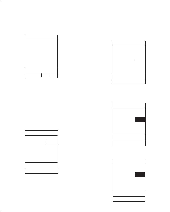
2.4.1Access System Configuration Options
1.Hold OPTIONS key at power up.
System Configuration - Module
Factory default: |
No |
Shared Infusion Settings
PC Unit
Pump Module
SPO2 Module
>Select an Option
or EXIT
EXIT |
PAGE |
|
DOWN |
||
|
2.Press PC Unit soft key. To view additional options, press PAGE DOWN soft key.
System Config - PCU 1 of 2
Alarm audio: |
Profile 1 |
Anesthesia Mode: Disabled |
|
Battery meter: |
Disabled |
Clock setup: |
09:00 |
Key click audio: |
Enabled |
>Select an Option or EXIT
PAGE
EXIT DOWN
-- Continued Next Page --
2-2 Alaris® PC Unit
Alaris® Pump Module
Technical Service Manual
CHECKOUT AND CONFIGURATION
2.4CONFIGURATION SETUP - PC UNIT
(Continued)
2.4.1Access System Configuration Options
(Continued)
System Config - PCU 2 of 2
Max Pt. weight: 500 kg
Patient ID Entry: Disabled
PM reminder: |
Disabled |
Profiles: Disabled
Tamper resist: Disabled
>Select an Option or EXIT
PAGE
UP EXIT
2.4.2 Alarm audio
There are 3 different alarm profiles that can be selected to help differentiate between audio alarms in certain hospital environments.
Audio alert patterns (±5%):
Profile 1: 500 ms ON, 1500 ms OFF,
500 ms ON
Profile 2: 100 ms ON, 500 ms OFF,
400 ms ON
2.To change profile selection, press soft key next to desired profile. To hear a sample of selected audio alarm, press Test soft key.
3.To accept setting, press Confirm soft key.
2.4.3Anesthesia Mode
The Anesthesia Mode allows access to additional drugs in each profile that is appropriate to anesthesiology. This mode also features permanent pause and the ability to set higher air-in-line settings.
1.After accessing System Config - PCU options display, press Anesthesia Mode soft key.
System Configuration - PCU
Anesthesia Mode |
Enable |
|
|
|
Disable |
|
|
|
|
|
|
Allows use of the Anesthesia
Mode feature.
Profile 3: 400 ms ON, 500 ms OFF,
400 ms ON
1.After accessing System Config - PCU options display, press Alarm audio soft key.
System Configuration - PCU
|
Profile |
|
Alarm audio profile |
1 |
|
selection |
Profile |
|
|
2 |
|
Select the desired alarm |
Profile |
|
audio patterns. Press Test |
3 |
|
to hear a sample of the |
Confirm |
|
selected profile. |
||
|
||
|
Test |
|
|
|
2.To change setting, press soft key next to applicable option (Enable or Disable).
2.4.4Battery meter
When Enable is selected, the approximate time remaining on the battery is displayed (in a numeric value). The run time depends on the battery charge/condition and the load on the battery at the time. Run time may also be affected by the operating mode, rate, monitoring options and back pressure. The battery meter reading may take up
to 5 minutes after starting an infusion to stabilize.
Alaris® PC Unit |
2-3 |
Alaris® Pump Module
Technical Service Manual

CHECKOUT AND CONFIGURATION
2.4CONFIGURATION SETUP - PC UNIT
(Continued)
2.4.4Battery meter (Continued)
1.After accessing System Config - PCU options display, press Battery meter soft key.
System Configuration - PCU
Battery meter |
Enable |
|
|
|
Disable |
|
|
|
|
|
|
Allows the pump to display remaining battery run time to the user.
2.To change time:
a. Press Change Time soft key.
System Configuration - PCU
Clock setup |
|
|
|
Current time: |
|
|
|
Change |
|
||
__:__ |
|
Time |
|
|
|
|
|
Current date: |
|
Change |
|
1998-12-15 |
|
Date |
|
|
|
|
|
>Enter Time-of-Day
b. Enter time.
System Configuration - PCU
Clock setup
Current time: Change
09:30 Time
2.To change setting, press soft key next to applicable option (Enable or Disable).
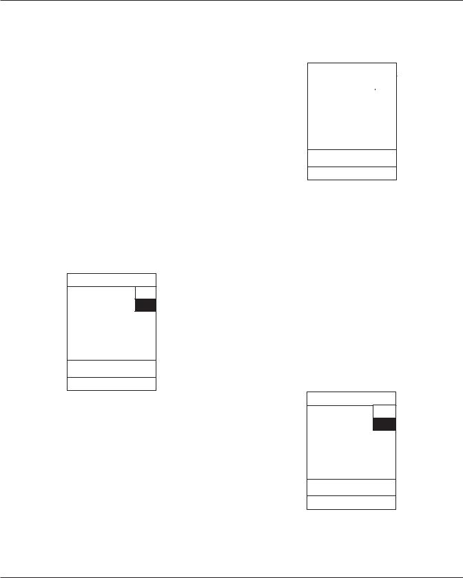
2.4.5Clock setup
Current date: Change
1998-12-15 Date
>Press CONFIRM
This option is used to set the time and date.
CONFIRM
1.After accessing System Config - PCU options display, press Clock setup soft key.
System Configuration - PCU
Clock setup
Current time: |
Change |
09:00 |
Time |
|
|
Current date: |
Change |
1998-12-15 |
Date |
|
>Confirm Time-of-Day and
Date
3.To change date:
a. Press Change Date soft key.
System Configuration - PCU
Clock setup |
|
|
Current time: |
|
|
Change |
||
09:30 |
|
Time |
|
|
|
Current date: |
|
Change |
yyyy-mm-dd |
|
Date |
|
|
|
>Enter Current Date
CONFIRM
CONFIRM
2-4 Alaris® PC Unit
Alaris® Pump Module
Technical Service Manual
CHECKOUT AND CONFIGURATION
2.4CONFIGURATION SETUP - PC UNIT
(Continued)
2.4.5Clock setup (Continued)
b. Enter date.
System Configuration - PCU
Clock setup
Current time: |
Change |
09:30 |
Time |
|
|
Current date: |
Change |
2001-01-29 |
Date |
|
>Press CONFIRM
CONFIRM
4.To accept settings, press CONFIRM soft key.
2.4.6Key click audio
This option is used to Enable or Disable the keypress audio feedback.
1.After accessing System Config - PCU options display, press Key click audio soft key.
System Configuration - PCU
Key click audio |
Enable |
|
|
|
|
Disable
Provides an audible sound with each keypress.
2.To change setting, press soft key next to applicable option (Enable or Disable).
2.4.7Max Pt. weight
This option is used to set the maximum patient weight.
1.After accessing System Config - PCU options display, page 2, press Max Pt. weight soft key.
System Configuration - PCU
Maximum patient weight adjustment
No
Maximum weight: |
|
|
Change |
||
500 kg |
||
value |
||
|
||
|
Confirm |
|
|
|
2.To change maximum weight:
a. Press Change value soft key.
System Configuration - PCU
Maximum patient weight adjustment
Maximum weight: Change |
|
_ _ _ _kg |
value |
|
|
b. Enter new weight.
System Configuration - PCU
Maximum patient weight adjustment
Maximum weight: |
Change |
_100 kg |
value |
|
|
|
Confirm |
|
|
Alaris® PC Unit |
2-5 |
Alaris® Pump Module
Technical Service Manual
CHECKOUT AND CONFIGURATION
2.4CONFIGURATION SETUP - PC UNIT
(Continued)
2.4.7Max Pt. weight (Continued)
3.To accept setting, press Confirm soft key.
2.4.8Patient ID Entry
Enabling the Patient ID feature allows an alphanumeric patient identifier to be entered in the Patient ID Entry screen that displays after responding Yes to New Patient?. When the Patient ID feature is disabled, the Patient ID Entry screen can only be accessed through the Systems Options menu.
1.After accessing System Config - PCU options display, page 2, press Patient ID Entry soft key.
System Configuration - PCU
Patient ID Entry |
Enable |
|
|
Disable
Allows the patient ID to be assigned at system start up.
1.After accessing System Config - PCU options display, page 2, press PM reminder soft key.
System Configuration - PCU
Preventive |
Enable |
|
Maintenance reminder |
|
|
Disable |
||
|
||
|
|
|
|
|
Notifies user at power on when modules are due for routine preventive maintenance.
2.To change setting, press soft key next to applicable option (Enable or Disable).
2.4.10Profiles
A profile is a unique set of system configuration settings and best-practice guidelines for a specific patient population or patient type. Profile settings are established prior to system implementation. The Profiles option can be enabled only when a Data Set is loaded. Disabling the Profiles option disables the loaded Data Set.
1.After accessing System Config - PCU options display, page 2, press Profiles soft key.
2.To change setting, press soft key next to applicable option (Enable or Disable).
2.4.9PM reminder
Enabling the PM reminder feature allows a MAINTENANCE REMINDER message to appear when the PC Unit or attached module is due for routine scheduled preventive maintenance.
System Configuration - PCU
Profiles |
Enable |
|
|
Disable
Allow the user to select from an institution defined list of Profiles
2.To change setting, press soft key next to applicable option (Enable or Disable).
2-6 Alaris® PC Unit
Alaris® Pump Module
Technical Service Manual
CHECKOUT AND CONFIGURATION
2.4CONFIGURATION SETUP - PC UNIT
(Continued)
2.4.11 Tamper resist
When Enable is selected, this mode can be activated or deactivated by pressing and holding the Tamper Resist Switch on the back of the PC Unit for 3 to 4 seconds. Reference the Alaris® System DFU for more detailed information.
Prior to accessing the Tamper resist mode, all modules that are to be operating must be set up.
System Configuration - PCU
Tamper resistant mode |
Enable |
|
|
||
|
|
Disable |
|
|
|
|
|
|
Allows use of the tamper |
Auth |
Resistant Mode feature. |
user |
|
Change |
|
override |
|
|
1.After accessing System Config - PCU options display, page 2, press Tamper resist soft key.
2.To change setting, press soft key next to applicable option (Enable or Disable).
2.5CONFIGURATION SETUP - PUMP MODULE
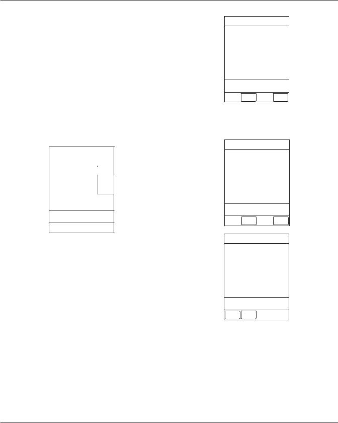
2.5.1Access System Configuration Options
1.Hold OPTIONS key at power up.
System Configuration - Module
Factory default: |
No |
Shared Infusion Settings
PC Unit
Pump Module
SPO2 Module
>Select an Option
or EXIT
EXIT |
PAGE |
|
DOWN |
||
|
2.Press Pump Module soft key. To view additional options, press PAGE DOWN soft key.
System Config - Pump 1 of 2
Accumulated air: Enabled
Air-in-line settings: 75microliter -
Auto-restart attempts: 0
KVO rate adjust:
Max rate:
>Select an Option or EXIT
EXIT
System Config - Pump 2 of 2
Max VTBI: |
9999 mL |
Pressure mode: Pump
SEC-PRI alert: Enabled
Secondary: Disabled
>Select an Option or EXIT
PAGE |
EXIT |
UP |
|
Alaris® PC Unit |
2-7 |
Alaris® Pump Module
Technical Service Manual

CHECKOUT AND CONFIGURATION
2.5CONFIGURATION SETUP - PUMP MODULE (Continued)
2.5.2Accumulated air
When Disable is selected, the air-in-line system detects a bolus size of »50, 75 or 250 microliters only. When Enable is selected, the air-in-line system detects a bolus size of »50, 75 or 250 microliters and a number of small boluses of a predetermined number, depending on the bolus size selected in the Air-in-line settings option.
1.After accessing System Config - Pump options display, press Accumulated air soft key.
System Configuration - Pump
Accumulated Enable
Air-in-line
Disable
Detects the presence of multiple small air bubbles.
2.To change setting, press soft key next to applicable option (Enable or Disable).
2.5.3Air-in-line settings
There are 3 different air-in-line bolus settings that can be selected; 50, 75 or 250 microliters. This is the amount of air allowed to pass through the detector before an air-in- line alarm sounds.
1.After accessing System Config - Pump options display, press Air-in-line settings soft key.
System Configuration - Pump
Air-in-line detection |
50 |
|
|
||
threshold |
75 |
|
(in microliters) |
||
|
||
Sets the upper limit |
250 |
|
for a single bolus of air |
|
|
|
||
to pass without alarm |
|
|
|
|
|
|
|
|
|
|
2.To change setting, press soft key next to applicable option.
2.5.4Auto-restart attempts
This setting determines the number of attempts (0 to 9) the instrument will make to restart the infusion (following detection of a patient-side occlusion) before it alarms "Occlusion".
1.After accessing System Config - Pump options display, press Auto-restart attempts soft key.
System Configuration - Pump 
Auto-Restart Mode |
Increase |
|
|
|
|
Attempts: |
Decrease |
|
|
0 |
Confirm |
Determines the number of attempts to restart the infusion following detection of a patient side occlusion before the pump will alarm.
2-8 Alaris® PC Unit
Alaris® Pump Module
Technical Service Manual

CHECKOUT AND CONFIGURATION
2.5CONFIGURATION SETUP - PUMP MODULE (Continued)
2.5.4Auto-restart attempts (Continued)
2.To set number of attempts, press
Increase or Decrease soft key.
•When the maximum number of attempts is selected, Increase is grayed-out (disabled).
System Configuration - Pump
Auto-Restart Mode |
Increase |
|
|
||
Attempts: |
Decrease |
|
3 |
|
|
Confirm |
||
|
||
|
|
Determines the number of attempts to restart the infusion following detection of a patient side occlusion before the pump will alarm.
3.To accept setting, press Confirm soft key.
2.5.5KVO rate adjust
This option is used to select the KVO (Keep Vein Open) rate (0.1 to 20 mL/h). This determines the rate of fluid flow after "Infusion Complete" has occurred.
1.After accessing System Config - Pump options display, press KVO rate adjust soft key.
System Configuration - Pump
KVO rate adjustment
KVO rate: |
Change |
|
KVO rate |
||
1 mL/h |
||
Confirm |
||
|
||
|
|
2.To change KVO rate:
a. Press Change KVO rate soft key.
System Configuration - Pump
KVO rate adjustment
KVO rate: |
Change |
|
KVO rate |
||
_ _ mL/h |
||
|
||
|
|
|
|
|
|
|
|
b. Enter desired rate.
System Configuration - Pump
KVO rate adjustment
KVO rate: |
Change |
|
KVO rate |
||
5 mL/h |
||
Confirm |
||
|
||
|
|
3.To accept setting, press Confirm soft key.
Alaris® PC Unit |
2-9 |
Alaris® Pump Module
Technical Service Manual

CHECKOUT AND CONFIGURATION
2.5CONFIGURATION SETUP - PUMP MODULE (Continued)
2.5.6Max rate
This option is used to select the maximum rate (0.1 to 999 mL/h).
1.After accessing System Config - Pump options display, press Change value soft key.
System Configuration - Pump
Maximum rate adjustment
Maximum rate: |
Change |
|
999 mL/h |
value |
|
Confirm |
||
|
||
|
|
2.To change rate:
a. Press Change value soft key.
System Configuration - Pump
Maximum rate adjustment
Maximum |
Change |
|
rate: |
value |
|
_ _ _ mL/h |
|
b. Enter desired rate.
System Configuration - Pump
Maximumrate |
|
|
adjustment |
|
|
Maximum rate: |
Change |
|
99.9 mL/h |
value |
|
Confirm |
||
|
3.To accept setting, press Confirm soft key.
2.5.7Max VTBI
This option is used to select the maximum VTBI adjustment rate (0.1 to 9999 mL).
1.After accessing System Config - Pump options display, page 2, press Max VTBI soft key.
System Configuration - Pump
Maximum VTBI adjustment
Maximum VTBI: |
Change |
|
9999 mL |
||
value |
||
|
Confirm |
2-10 Alaris® PC Unit
Alaris® Pump Module
Technical Service Manual

CHECKOUT AND CONFIGURATION
2.5CONFIGURATION SETUP - PUMP MODULE (Continued)
2.5.7Max VTBI (Continued)
2.To change rate:
a. Press Change value soft key.
System Configuration - Pump
Maximum VTBI adjustment
Maximum VTBI: |
Change |
|
_ _ _ _ mL |
value |
|
|
|
Selectable: Occlusion limit of 50 to
525 mmHg (approximately 1 to 10.2 psi), in
25 mmHg increments, can be selected.
1.After accessing System Config - Pump options display, page 2, press Pressure mode soft key.
System Configuration - Pump
Pressure mode |
Pump |
|
selection |
|
|
Selectable |
||
Pressure mode: |
||
|
||
Pump |
Change |
|
|
Lock Status |
|
|
|
|
Lock status: |
|
|
Unlocked |
|
CONFIRM
b. Enter desired rate.
System Configuration - Pump
Maximum VTBI adjustment
Maximum VTBI: |
Change |
|
999.9 mL |
value |
|
Confirm |
||
|
||
|
|
|
|
|
|
|
|
|
|
|
3.To accept setting, press Confirm soft key.
2.5.8Pressure mode
There are 2 pressure modes available that determine the patient-side occlusion limit. The selected mode can be Unlocked or Locked after being confirmed.
Pump: Instrument will occlude at approximately 10 psi pressure.
2.To change setting:
a.Ensure lock status is Unlocked.
b.Press soft key next to applicable option (Pump or Selectable).
•If Selectable mode is selected, following screen displays.
System Configuration
Selectable Max |
|
Up |
|
Pressure: |
|
Down |
|
525 mmHg |
|
||
|
|
||
|
|
||
|
|
|
|
Selectable |
|
Up |
|
Default Pressure: |
|
||
Down |
|||
300 mmHg |
|
||
|
|
||
|
|
||
|
|
|
|
|
|
|
|
|
CONFIRM |
||
Alaris® PC Unit |
2-11 |
Alaris® Pump Module
Technical Service Manual
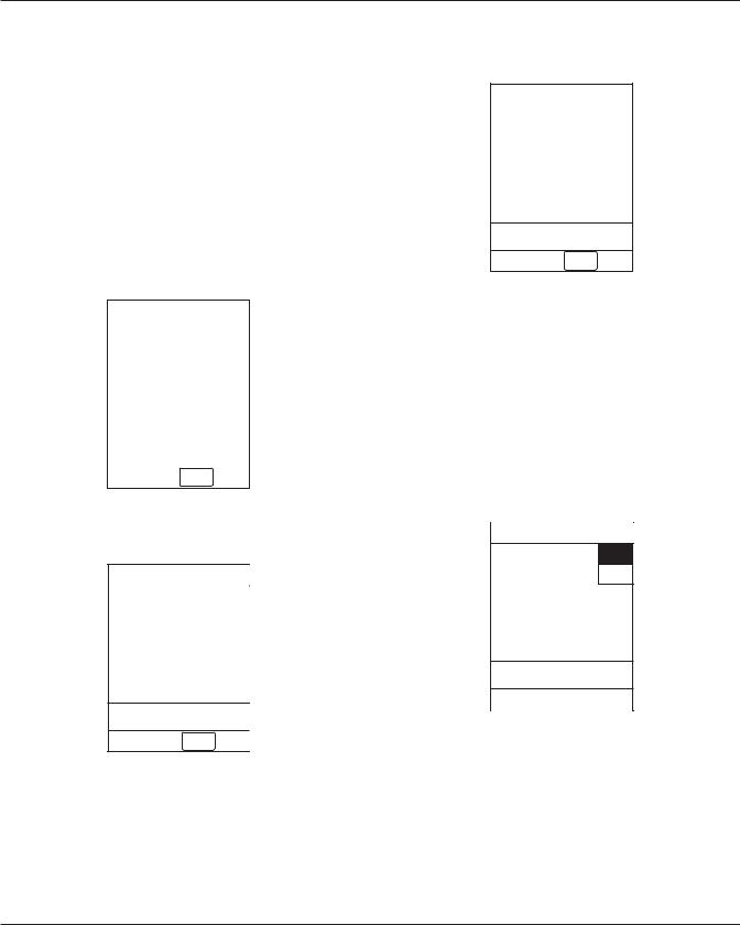
CHECKOUT AND CONFIGURATION
2.5CONFIGURATION SETUP - PUMP MODULE (Continued)
2.5.8Pressure mode (Continued)
3.To change pressure setting:
a.Press Up or Down soft key next to applicable option.
•When maximum pressure setting is selected, Up is grayed-out (disabled). When minimum pressure setting is selected, Down is grayed-out (disabled).
c.To lock selection, press Change Lock Status soft key.
System Configuration - Pump
Pressure mode |
Pump |
selection |
|
|
Selectable |
Pressure mode: |
|
Change |
|
Selectable |
Lock Status |
350 mmHg |
|
Lock status: |
|
Locked |
|
CONFIRM
System Configuration
Selectable Max |
|
Up |
|
Pressure: |
|
|
|
|
Down |
||
400 mmHg |
|
||
|
|
||
|
|
||
|
|
|
|
Selectable |
|
Up |
|
Default Pressure: |
|
||
Down |
|||
350 mmHg |
|
||
|
|
||
|
|
||
|
|
|
|
|
|
|
|
|
CONFIRM |
||
4.To accept setting, press CONFIRM soft key.
2.5.9SEC-PRI alert
When Enable is selected, an alarm sounds when the instrument switches from Secondary to Primary mode.
1.After accessing System Config - Pump options display, page 2, press SEC-PRI alert soft key.
b.To accept setting, press CONFIRM soft key.
System Configuration - Pump
Pressure mode |
Pump |
|
selection |
|
|
|
Selectable |
|
|
|
|
Pressure mode: |
Change |
|
Selectable |
Lock Status |
|
|
||
350 mmHg |
|
|
Lock status: |
|
|
Unlocked |
|
|
CONFIRM
System Configuration - Pump 
Secondary to |
Enable |
|
primary transition |
|
|
|
|
|
alert |
Disable |
|
|
|
|
Causes six audio tones to sound when the infusion transitions from secondary to primary.
2.To change setting, press soft key next to applicable option (Enable or Disable).
2-12 Alaris® PC Unit
Alaris® Pump Module
Technical Service Manual
 Loading...