


Technical Service Manual
Alaris® EtCO2 Module, 8300 Series
Supports: Guardrails® Suite (v7 or later)
January 2006
ALARM
MONIT
OR
STAN
DBY
EtCO2 (mm Hg)
RR (breaths/min)
CHANNEL
SELECT
MONITOR
CHANNEL
OFF
Alaris® Products

General Contact Information
Cardinal Health
Alaris® Products
10221 Wateridge Circle
San Diego, California 92121 http://www.cardinal.com/alaris
Customer Advocacy - North America
Clinical and technical feedback.
Phone: 800.854.7128, Ext. 7812
E-Mail: CustomerFeedback@cardinal.com
Technical Support - North America
Maintenance and service information support; troubleshooting.
United States: |
Canada: |
Phone: |
Phone: |
858.458.6003 |
Eastern: 800.908.9918 |
800.854.7128, Ext. 6003 |
Western: 800.908.9919 |
Customer Care - North America
Instrument return, service assistance, and order placement.
United States: |
Canada: |
Phone: 800.482.4822 |
Phone: 800.387.8309 |
|
|
This Technical Service Manual is subject to change without notification.
Alaris® EtCO2 Module (8300 Series)
Technical Service Manual

|
|
TABLE OF CONTENTS |
|
|
|
Chapter 1 - General Information |
|
|
1.1 |
Introduction . . . . . . . . . . . . . . . . . . . . . . . . . . . . . . . . . . . . . . . . . . . . . . . . . . . . . . . . . |
. . . . . . . . . . . . . . . . . . . . . . . . . . . . . . . . . . . 1-1 |
1.2 |
Precaution Definitions . . . . . . . . . . . . . . . . . . . . . . . . . . . . . . . . . . . . . . . . . . . . . . |
. . . . . . . . . . . . . . . . . . . . . . . . . . . . . . . . . . 1-2 |
1.3 |
Specifications . . . . . . . . . . . . . . . . . . . . . . . . . . . . . . . . . . . . . . . . . . . . . . . . . . . . . . . |
. . . . . . . . . . . . . . . . . . . . . . . . . . . . . . . . . . 1-2 |
1.4 |
Operating Features, Controls and Indicators . . . . . . . . . . . . . . . . . . . . . |
. . . . . . . . . . . . . . . . . . . . . . . . . . . . . . . . . . 1-2 |
1.5 |
Alarms, Errors, Messages . . . . . . . . . . . . . . . . . . . . . . . . . . . . . . . . . . . . . . . . . |
. . . . . . . . . . . . . . . . . . . . . . . . . . . . . . . . . . 1-2 |
1.5.1 |
Silencing Alarms . . . . . . . . . . . . . . . . . . . . . . . . . . . . . . . . . . . . . . . . . . . . . . . . . . . . |
. . . . . . . . . . . . . . . . . . . . . . . . . . . . . . . . . . 1-2 |
Chapter 2 - Checkout and Configuration |
|
|
2.1 |
Introduction . . . . . . . . . . . . . . . . . . . . . . . . . . . . . . . . . . . . . . . . . . . . . . . . . . . . . . . . . . |
. . . . . . . . . . . . . . . . . . . . . . . . . . . . . . . . . . 2-1 |
2.2 |
New Instrument Checkout . . . . . . . . . . . . . . . . . . . . . . . . . . . . . . . . . . . . . . . . . |
. . . . . . . . . . . . . . . . . . . . . . . . . . . . . . . . . . 2-1 |
2.3 |
Configuration Options and Defaults . . . . . . . . . . . . . . . . . . . . . . . . . . . . . . . |
. . . . . . . . . . . . . . . . . . . . . . . . . . . . . . . . . . 2-2 |
2.4 |
Configuration Setup - EtCO2 . . . . . . . . . . . . . . . . . . . . . . . . . . . . . . . . . . . . . . |
. . . . . . . . . . . . . . . . . . . . . . . . . . . . . . . . . . 2-3 |
2.4.1 |
Alarm Limits . . . . . . . . . . . . . . . . . . . . . . . . . . . . . . . . . . . . . . . . . . . . . . . . . . . . . . . . . |
. . . . . . . . . . . . . . . . . . . . . . . . . . . . . . . . . . 2-3 |
2.4.2 |
Limit Mode . . . . . . . . . . . . . . . . . . . . . . . . . . . . . . . . . . . . . . . . . . . . . . . . . . . . . . . . . . |
. . . . . . . . . . . . . . . . . . . . . . . . . . . . . . . . . . 2-4 |
2.4.3 |
Waveform Height . . . . . . . . . . . . . . . . . . . . . . . . . . . . . . . . . . . . . . . . . . . . . . . . . . . |
. . . . . . . . . . . . . . . . . . . . . . . . . . . . . . . . . . 2-5 |
2.4.4 |
Waveform Time Scale . . . . . . . . . . . . . . . . . . . . . . . . . . . . . . . . . . . . . . . . . . . . . . |
. . . . . . . . . . . . . . . . . . . . . . . . . . . . . . . . . . 2-5 |
Chapter 3 - Preventive Maintenance
3.1 |
Introduction . . . . . . . . . . . . . . . . . . . . . . . . . . . . . . . . . . . . . . . . . . . . . . . . . . . . . . . . . . . . . . . . . . . . . . . . . . . . . . . . . . . . . . . . . . . . |
3.2 |
Regular and Preventive Maintenance Inspections, Calibrations . . . . . . . . . . . . . . . . . . . . . . . . . . . . . . . . . . |
3.3 |
Cleaning . . . . . . . . . . . . . . . . . . . . . . . . . . . . . . . . . . . . . . . . . . . . . . . . . . . . . . . . . . . . . . . . . . . . . . . . . . . . . . . . . . . . . . . . . . . . . . . |
3-1
3-1
3-1
Chapter 4 - Principles of Operation
4.1 |
Introduction . . . . . . . . . . . . . . . . . . . . . . . . . . . . . . . . . . . . . . . . . . . . . . . . . . . . . . . . . . . . . . . . . . . . . . . . . . . . . . . . . . . . . . . . . . . . |
4-1 |
4.2 |
General Information . . . . . . . . . . . . . . . . . . . . . . . . . . . . . . . . . . . . . . . . . . . . . . . . . . . . . . . . . . . . . . . . . . . . . . . . . . . . . . . . . . |
4-1 |
Alaris® EtCO2 Module (8300 Series)
Technical Service Manual
i

TABLE OF CONTENTS
Chapter 5 - Corrective Maintenance
5.1 |
Introduction . . . . . . . . . . . . . . . . . . . . . . . . . . . . . . . . . . . . . . . . . . . . . . . . . . . . . . . . . . . . . . . . . . . . . . . . . . . . . . . . . . . . . . . . . . . . |
5-1 |
5.2 |
Disassembly/Reassembly . . . . . . . . . . . . . . . . . . . . . . . . . . . . . . . . . . . . . . . . . . . . . . . . . . . . . . . . . . . . . . . . . . . . . . . . . . . . |
5-2 |
5.2.1 |
Latch Assembly and Feet . . . . . . . . . . . . . . . . . . . . . . . . . . . . . . . . . . . . . . . . . . . . . . . . . . . . . . . . . . . . . . . . . . . . . . . . . . . . |
5-3 |
5.2.2 |
IUI Connectors . . . . . . . . . . . . . . . . . . . . . . . . . . . . . . . . . . . . . . . . . . . . . . . . . . . . . . . . . . . . . . . . . . . . . . . . . . . . . . . . . . . . . . . . |
5-4 |
5.2.3 |
Rear Case . . . . . . . . . . . . . . . . . . . . . . . . . . . . . . . . . . . . . . . . . . . . . . . . . . . . . . . . . . . . . . . . . . . . . . . . . . . . . . . . . . . . . . . . . . . . . |
5-5 |
5.2.4 |
Frame Assembly . . . . . . . . . . . . . . . . . . . . . . . . . . . . . . . . . . . . . . . . . . . . . . . . . . . . . . . . . . . . . . . . . . . . . . . . . . . . . . . . . . . . . . |
5-6 |
5.2.5 |
Logic Board . . . . . . . . . . . . . . . . . . . . . . . . . . . . . . . . . . . . . . . . . . . . . . . . . . . . . . . . . . . . . . . . . . . . . . . . . . . . . . . . . . . . . . . . . . . |
5-7 |
5.2.6 |
Power Board/Oridion Module . . . . . . . . . . . . . . . . . . . . . . . . . . . . . . . . . . . . . . . . . . . . . . . . . . . . . . . . . . . . . . . . . . . . . . . . |
5-8 |
5.2.7 |
IUI Bracket . . . . . . . . . . . . . . . . . . . . . . . . . . . . . . . . . . . . . . . . . . . . . . . . . . . . . . . . . . . . . . . . . . . . . . . . . . . . . . . . . . . . . . . . . . . . |
5-9 |
5.2.8 |
Gas Inlet/Outlet Door . . . . . . . . . . . . . . . . . . . . . . . . . . . . . . . . . . . . . . . . . . . . . . . . . . . . . . . . . . . . . . . . . . . . . . . . . . . . . . . . . |
5-10 |
5.2.9 |
Luer Assembly . . . . . . . . . . . . . . . . . . . . . . . . . . . . . . . . . . . . . . . . . . . . . . . . . . . . . . . . . . . . . . . . . . . . . . . . . . . . . . . . . . . . . . . . |
5-11 |
5.2.10 |
Display Board . . . . . . . . . . . . . . . . . . . . . . . . . . . . . . . . . . . . . . . . . . . . . . . . . . . . . . . . . . . . . . . . . . . . . . . . . . . . . . . . . . . . . . . . . |
5-12 |
5.2.11 |
Status Indicator Lens . . . . . . . . . . . . . . . . . . . . . . . . . . . . . . . . . . . . . . . . . . . . . . . . . . . . . . . . . . . . . . . . . . . . . . . . . . . . . . . . . |
5-13 |
Chapter 6 - Troubleshooting
6.1 Introduction . . . . . . . . . . . . . . . . . . . . . . . . . . . . . . . . . . . . . . . . . . . . . . . . . . . . . . . . . . . . . . . . . . . . . . . . . . . . . . . . . . . . . . . . . . . . 6-1
Chapter 7 - Illustrated Parts Breakdown
7.1 |
Introduction . . . . . . . . . . . . . . . . . . . . . . . . . . . . . . . . . . . . . . . . . . . . . . . . . . . . . . . . . . . . . . . . . . . . . . . . . . . . . . . . . . . . . . . . . . . . |
7.2 |
Illustrations . . . . . . . . . . . . . . . . . . . . . . . . . . . . . . . . . . . . . . . . . . . . . . . . . . . . . . . . . . . . . . . . . . . . . . . . . . . . . . . . . . . . . . . . . . . . |
7.3 |
Parts List . . . . . . . . . . . . . . . . . . . . . . . . . . . . . . . . . . . . . . . . . . . . . . . . . . . . . . . . . . . . . . . . . . . . . . . . . . . . . . . . . . . . . . . . . . . . . . |
7.4 |
Ordering Parts . . . . . . . . . . . . . . . . . . . . . . . . . . . . . . . . . . . . . . . . . . . . . . . . . . . . . . . . . . . . . . . . . . . . . . . . . . . . . . . . . . . . . . . . |
7-1
7-1
7-1
7-2
ii
Alaris® EtCO2 Module (8300 Series)
Technical Service Manual

|
|
TABLE OF CONTENTS |
|
|
|
List of Tables |
|
|
2-1 |
Record of Configured Instruments . . . . . . . . . . . . . . . . . . . . . . . . . . . . . . . . . . . . . . . . . . . . |
. . . . . . . . . . . . . . . . . . . . . . 2-7 |
5-1 |
Required Materials, Supplies and Tools . . . . . . . . . . . . . . . . . . . . . . . . . . . . . . . . . . . . . . |
. . . . . . . . . . . . . . . . . . . . . . 5-2 |
5-2 |
Torque Values . . . . . . . . . . . . . . . . . . . . . . . . . . . . . . . . . . . . . . . . . . . . . . . . . . . . . . . . . . . . . . . . . . |
. . . . . . . . . . . . . . . . . . . . . . 5-14 |
5-3 |
Level of Testing Guidelines . . . . . . . . . . . . . . . . . . . . . . . . . . . . . . . . . . . . . . . . . . . . . . . . . . . . |
. . . . . . . . . . . . . . . . . . . . . . 5-15 |
6-1 |
Technical Troubleshooting Guide . . . . . . . . . . . . . . . . . . . . . . . . . . . . . . . . . . . . . . . . . . . . . |
. . . . . . . . . . . . . . . . . . . . . . 6-2 |
6-2 |
Malfunction Codes . . . . . . . . . . . . . . . . . . . . . . . . . . . . . . . . . . . . . . . . . . . . . . . . . . . . . . . . . . . . . . |
. . . . . . . . . . . . . . . . . . . . . . 6-3 |
7-1 |
Parts List . . . . . . . . . . . . . . . . . . . . . . . . . . . . . . . . . . . . . . . . . . . . . . . . . . . . . . . . . . . . . . . . . . . . . . . . |
. . . . . . . . . . . . . . . . . . . . . . 7-2 |
List of Figures |
|
|
7-1 |
Housing Assembly . . . . . . . . . . . . . . . . . . . . . . . . . . . . . . . . . . . . . . . . . . . . . . . . . . . . . . . . . . . . . . |
. . . . . . . . . . . . . . . . . . . . . . 7-5 |
7-2 |
Frame/Front Case Assembly . . . . . . . . . . . . . . . . . . . . . . . . . . . . . . . . . . . . . . . . . . . . . . . . . . |
. . . . . . . . . . . . . . . . . . . . . . 7-6 |
7-3 |
IUI Bracket/Frame Assembly . . . . . . . . . . . . . . . . . . . . . . . . . . . . . . . . . . . . . . . . . . . . . . . . . . |
. . . . . . . . . . . . . . . . . . . . . . 7-7 |
7-4 |
Oridion Module/Power Supply Board . . . . . . . . . . . . . . . . . . . . . . . . . . . . . . . . . . . . . . . . . |
. . . . . . . . . . . . . . . . . . . . . . 7-8 |
7-5 |
Front Case Assembly . . . . . . . . . . . . . . . . . . . . . . . . . . . . . . . . . . . . . . . . . . . . . . . . . . . . . . . . . . |
. . . . . . . . . . . . . . . . . . . . . . 7-9 |
7-6 |
Rear Case Assembly/Latch Kit . . . . . . . . . . . . . . . . . . . . . . . . . . . . . . . . . . . . . . . . . . . . . . . . |
. . . . . . . . . . . . . . . . . . . . . . 7-10 |
7-7 |
EtCO2 Cable Assembly . . . . . . . . . . . . . . . . . . . . . . . . . . . . . . . . . . . . . . . . . . . . . . . . . . . . . . . . |
. . . . . . . . . . . . . . . . . . . . . . 7-11 |
Alaris® EtCO2 Module (8300 Series)
Technical Service Manual
iii

TABLE OF CONTENTS
T H I S PA G E
I N T E N T I O N A L LY
L E F T B L A N K
iv
Alaris® EtCO2 Module (8300 Series)
Technical Service Manual
1 GENERAL INFORMATION

Chapter 1 — GENERAL INFORMATION
CAUTION |
1.1 INTRODUCTION |
To avoid damaging the keypad, do not use sharp objects (pens, pencils, etc.) to activate switches.
CAUTION
Any attempt to service this product by anyone other than an authorized Cardinal Health Service Representative while the product is under warranty may invalidate the warranty.
This manual describes how to service the Alaris® EtCO2 module 8300 Series (“EtCO2 Module”). Use this manual in conjunction with the following Alaris® System documents and software:
•Alaris® PC point-of-care unit 8000 Series (“PC Unit”) / Alaris® Pump module 8100 Series (“Pump Module”) Technical Service Manual
•The PC Unit section of the Alaris® System Directions for Use (DFU)
•The EtCO2 Module section of the Alaris® System DFU
•Maintenance Software User Manual (version 7 or later)
This manual is intended for personnel experienced in analysis, troubleshooting, and repair of analog/digital microprocessorbased medical equipment.
The EtCO2 Module is a capnograph indicated for continuous, noninvasive monitoring of end tidal carbon dioxide (EtCO2), fractional inspired carbon dioxide (FiCO2) and respiratory rate (RR). The EtCO2 Module and disposables are indicated for use with intubated and nonintubated adult, pediatric, and neonatal patients. It is not intended for direct connection to ventilator or breathing systems. Only one (1) EtCO2 Module can be connected to the Alaris® System.
The EtCO2 Module is used with Oridion’s patented Microstream® Disposables/circuits for sidestream capnography.
Alaris® EtCO2 Module (8300 Series) |
1-1 |
Technical Service Manual |
|

GENERAL INFORMATION
1.2 |
PRECAUTION DEFINITIONS |
1.5 ALARMS, ERRORS, MESSAGES |
|
Refer to the Alaris® System DFU. |
The scrolling Channel Message Display bar |
1.3 |
SPECIFICATIONS |
shows alarms and other messages. Refer |
to the product-specific (EtCO2 Module) |
||
|
Refer to the product-specific (EtCO2 |
section of the Alaris® System DFU for |
|
detailed information. |
|
|
Module) section of the Alaris® System DFU. |
1.4OPERATING FEATURES, CONTROLS AND INDICATORS
Refer to the product-specific section of the Alaris® System DFU.
1.5.1Silencing Alarms
All alarms can be temporarily silenced by pressing the SILENCE key on the PC Unit.
WARNING
If an alarm condition on the EtCO2 Module occurs while the audio alarm is silenced, the only alarm indications will be visual displays and symbols related to the alarm condition.
1-2 Alaris® EtCO2 Module (8300 Series)
Technical Service Manual
2 CHECKOUT & CONFIGURATION

Chapter 2 — CHECKOUT AND CONFIGURATION
CAUTION
Should an instrument be jarred severely or dropped, remove it from use immediately. It should be thoroughly tested and inspected by qualified service personnel to ensure proper function prior to reuse.
2.1INTRODUCTION
This chapter describes the initial setup and configuration for the EtCO2 Module.
2.2NEW INSTRUMENT CHECKOUT
Refer to the EtCO2 Module Directions for Use (DFU) for instructions regarding unpacking and setting up the instrument for first time use.
When powering up the instrument, verify the instrument beeps and all display LED segments flash. This confirms that the instrument has performed its self test and is operating correctly. During operation, the instrument continually performs a self test, and will alarm and display a message if it detects an internal malfunction.
Contact Cardinal Health authorized service personnel if the instrument has physical damage, fails to satisfactorily pass the startup sequence, fails a self test, or continues to alarm.
For new instrument checkout, the minimum checks (described in the Maintenance Software User Manual) are:
•Regular Inspection
•Functional Tests
Alaris® EtCO2 Module (8300 Series) |
2-1 |
Technical Service Manual |
|

CHECKOUT AND CONFIGURATION
2.3CONFIGURATION OPTIONS AND DEFAULTS
NOTES:
•Changes to the factory default values are retained after a power cycle.
EtCO2 Module settings (including limit mode, high and low respiratory rate alarm limit, high and low EtCO2 alarm limit, no breath alarm setting, and high FiCO2 alarm limit).
•If Factory Default is Yes, then all the configuration settings are set to their factory default.
•If Factory Default is No, then one or more of the configuration settings has been changed. If desired, Factory Default can be selected and set to Yes, which will set all configuration settings to their factory default.
•With the Profiles feature enabled, the settings are configured independently for each profile. A hospital-defined, bestpractice data set must be uploaded to enable the Profiles feature. Date and Time is a system setting and is the same in all profiles.
System Settings: Refer to the PC Unit section of the Alaris® System DFU for information on system settings (including alarm audio profile, battery meter enable/disable, clock setup, key click audio enable, tamper resist enable/disable).
EtCO2 Module Settings: Refer to the product-specific (EtCO2 Module) section of the Alaris® System DFU for information on
NOTES:
•Pressing the EXIT soft key while in a
System Config - Module screen immediately powers the system down, with no “Powering Down” display.
•Pressing the EXIT soft key while in a
System Config - EtCO2 screen returns the display to the main System Config - Module screen.
•Pressing the CONFIRM soft key while in a System Configuration option screen:
♦accepts existing setting or setting change
♦displays next option setting screen (if applicable) or returns display to System Config - EtCO2 screen
•Pressing the Point-of-Care Unit’s CANCEL key while in a System Configuration option screen:
♦leaves setting unchanged
♦returns display to System Config - EtCO2 screen
2-2 |
Alaris® EtCO2 Module (8300 Series) |
|
Technical Service Manual |

CHECKOUT AND CONFIGURATION
2.4CONFIGURATION SETUP
To access System Configuration options:
NOTE: Refer to EtCO2 Module DFU for
alarm settings. If profiles are enabled, those settings are set by the profile.
1. Hold OPTIONS key at power up.
2. Press PAGE DOWN soft key.
3. Press EtCO2 Module soft key.
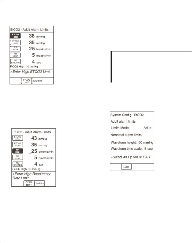
2.4.1Alarm Limits
NOTE: The following examples show adult alarm limits for illustration. Follow the same steps for neonatal alarm limits.
1.From the System Config - EtCO2 display, press the Adult alarm limits or
Neonatal alarm limits soft key.
2.To change an alarm limit, press the soft key next to that parameter. The selected parameter is highlighted.
Alaris® EtCO2 Module (8300 Series) |
2-3 |
Technical Service Manual |
|
CHECKOUT AND CONFIGURATION
2.4CONFIGURATION SETUP (Continued)
2.4.1Alarm Limits (Continued)
3.Enter a numeric value for the selected alarm limit. Use the numeric keypad or the up or down arrow keys to enter the value. If a valid value appears in the field for three seconds, the display shows the prompt > Press CONFIRM to Apply Changes.
4.Press ENTER on the Point-of-Care Unit to confirm the value. Once you press ENTER, the next limit is highlighted and the display prompts for an entry.
5.To change another alarm limit, press the soft key for that parameter and enter a new value.
6.Once all changes are complete, press the CONFIRM soft key.
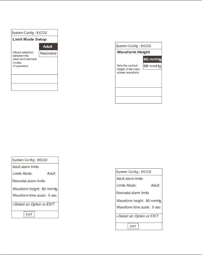
2.4.2Limit Mode
NOTES:
•The following examples show adult alarm limits for illustration. Follow the same steps for neonatal alarm limits.
•If a profile is in use for programming, you cannot change the Limit Mode.
1.To change the Limit Mode, toggle its value from the System Config - EtCO2 display, or use the Limits mode soft key.
Press the Limits Mode soft key to toggle between the two acceptable values
2.To toggle the value: From the System Config - EtCO2 display, press the soft key for the Limit Mode selection. Every key press toggles the value between Adult and Neonatal.
3.To use the soft key: From the System Config - EtCO2 display, press the
Limits Mode soft key.
2-4 |
Alaris® EtCO2 Module (8300 Series) |
|
Technical Service Manual |
CHECKOUT AND CONFIGURATION
2.4CONFIGURATION SETUP (Continued)
2.4.2Limit Mode (Continued)
4.Press the soft key to select the Limit Mode Setup display, or press CANCEL to exit the System Config - EtCO2 display without changing the value.
2.4.3Waveform Height
1.To change the waveform height, you can toggle its value from the System Config - EtCO2 display, or you can use the
Waveform height soft key.
Every key press toggles the value between 60 and 99 mmHg.
3.To use the soft key: From the System Config - EtCO2 display, press the
Waveform height soft key.
4.Press the soft key to select the waveform height, or press CANCEL to exit the Waveform Height display without changing the value.
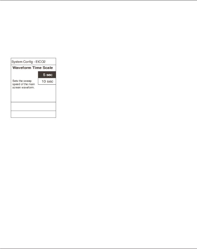
2.4.4Waveform Time Scale
1.To change the waveform time scale, you can toggle its value from the System Config - EtCO2 display, or you can use the Waveform time scale soft key.
Press the
Waveform height soft key to toggle between the two acceptable values
2.To toggle the value: From the System Config - EtCO2 display, press the soft key for the waveform height value.
Press the
Waveform time scale soft key to toggle between the two acceptable values
Alaris® EtCO2 Module (8300 Series) |
2-5 |
Technical Service Manual |
|
CHECKOUT AND CONFIGURATION
2.4CONFIGURATION SETUP (Continued)
2.4.4Waveform Time Scale (Continued)
2.To toggle the value: From the System Config - EtCO2 display, press the soft key for the Waveform Time Scale value. Every key press toggles the value between 5 and 10 sec.
3.To use the soft key: From the System Config - EtCO2 display, press the
Waveform time scale soft key.
4.Press the soft key to select the waveform height, or press CANCEL to exit the Waveform time scale display without changing the value.
2-6 |
Alaris® EtCO2 Module (8300 Series) |
|
Technical Service Manual |

CHECKOUT AND CONFIGURATION
Table 2-1. Record of Configured Instruments
#1 |
#2 |
#3 |
#4 |
|
|
|
|
Instrument ID/Serial #
EtCO2 Alarm Limit, High
EtCO2 Alarm Limit, Low
FiCO2 Alarm Limit, High
Limit Mode
No Breath Alarm
Respiratory Rate Alarm
Limit, High
Respiratory Rate Alarm
Limit, Low
Waveform Height
Waveform Time Scale
NOTE: If profiles are enabled, alarm limits are set by the profile.
Alaris® EtCO2 Module (8300 Series) |
2-7 |
Technical Service Manual |
|

CHECKOUT AND CONFIGURATION
T H I S PA G E
I N T E N T I O N A L LY
L E F T B L A N K
2-8 |
Alaris® EtCO2 Module (8300 Series) |
|
Technical Service Manual |
3 PREVENTIVE MAINTENANCE
 Loading...