


Alaris®Gateway Workstation
Technical Service Manual

This manual has been prepared for use by qualified service personnel only.
Cardinal Health cannot accept any liability for any breakdown or deterioration in performance of parts or equipment resulting from unauthorised repair or modification.
t Cardinal Health, 1180 Rolle, Switzerland
Alaris® and Asena® are registered trademarks of Cardinal Health, Inc. or one of its subsidiaries.
All other trademarks are the property of their respective owners.
© 2005-2008 Cardinal Health, Inc. or one of its subsidiaries. All rights reserved.
Alaris® Gateway Workstation |
2/67 |
1000SM00015 Issue 4 |

Contents
Chapter |
|
|
1. |
General Information |
4 |
2. |
Routine Maintenance |
8 |
3. |
Troubleshooting |
17 |
4. |
Circuit Descriptions |
19 |
5. |
Spare Parts Replacement Procedures |
22 |
Appendix |
|
|
A. |
Electromagnetic Compatibility |
51 |
B. |
Spare Parts Listing |
56 |
C. |
Disposal |
62 |
D. |
Service Contacts |
64 |
E. |
Document History |
66 |
Alaris® Gateway Workstation |
3/67 |
1000SM00015 Issue 4 |
Chapter 1
General Information
In this chapter
Introduction |
5 |
General Precautions |
6 |
Features of the Workstation |
7 |
General Information
Introduction
The Alaris® Gateway Workstation (herein after referred to as "Workstation") has been designed as a modular system providing a communications gateway between the Alaris® Infusion Pump and any Patient Data Management System (PDMS), Patient Monitoring (PM) System or Clinical Information System (CIS) that requires access to the infusion data retained within the pump.
•Central management system for multiple Alaris® Infusion Pumps
•Medical Device Interface (MDI) – a unique mounting mechanism providing data communications and mains power to the Alaris® Infusion Pump
•Reduced cable clutter with the use of a single AC power inlet
•Simple to set up with adaptable modular design
•Efficient organisation of multiple infusion lines and configurations
•Battery back-up in the event of power supply interruption
•Optional high visibility beacon assists with the location of pumps in an alarm state
•Nurse call interface for all Alaris® Infusion Pumps attached to the Workstation
•Software running on the Workstation allows remote access to the device
The device supports optional upgrades to enhance the data communication interfaces and to support software for connections to such client / server systems.
Data can be accessed and the software installed on the Workstation can be configured from a client PC using a standard Web browser; this may be performed over an Ethernet network or by directly linking to the Workstation.
The software is provided under and is subject to a license from Cardinal Health, Inc.
The Asena® brand name has been recently changed to the Alaris® brand name. This change in brand name has no effect on the intended use or functionality of the product.
Product Familiarity
The Workstation provides power and communications for the complete range of Alaris® Infusion Pumps (excluding the Alaris® System).
Prior to operation of the Workstation and prior to attempting any repairs or servicing, carefully read the Directions for Use (DFU)
As part of continuous improvement, product enhancements and changes are introduced from time to time.
Purpose of this Manual
This Technical Service Manual describes how to set up, test and maintain the Workstation. This manual is intended for use by personnel experienced in medical equipment testing and maintenance procedures.
Conventions Used in this Manual
BOLD |
Used for Workstation controls and indicators and Web Service software buttons referenced in this |
||
|
|
|
manual, for example, ON/OFF button, press OK to continue. |
|
|
|
|
|
'Single quotes' |
Used to indicate cross-references made to another section of this manual. For example, see Chapter 2, |
|
|
|
|
'Configuration & Calibration' |
|
|
|
|
underline |
Used to indicate links to another section of this manual. |
||
|
|
|
|
Italics |
Used to refer to other documents or manuals. For example, refer to the relevant Directions for Use (DFU) |
||
|
|
|
for further information. Also used for emphasis, for example, ...position the narrow end of the tool... |
|
|
|
|
|
|
|
Wherever this symbol is shown a Hints & Tips note is found. These notes provide useful advice or |
|
|
|
information that may help to perform the task more effectively. |
Wherever this symbol is shown a Toolbox note is found. These notes highlight an aspect of test or maintenance that is important to know about. A typical example is drawing attention to a software upgrade that should be checked that it has been installed.
Alaris® Gateway Workstation |
5/67 |
1000SM00015 Issue 4 |

General Information
General Precautions
wPrior to using the Workstation, carefully read the Operating Precautions in the Directions for Use (DFU).
VThis Workstation contains static sensitive components. Observe strict precautions for the protection of static sensitive components when attempting to repair and service the Workstation.
BAn explosion hazard exists if the equipment is used in the presence of flammable anaesthetics. Exercise care to locate the equipment away from any such hazardous sources.
ADangerous Voltage. An electrical shock hazard exists if the Workstation casing is opened or removed. Refer all servicing to qualified service personnel.
If the equipment is dropped, subjected to excessive moisture or spillage, humidity or high temperature, or otherwise suspected to have been damaged, remove it from service for inspection by qualified service personnel.
Refer all servicing to qualified service personnel only. Circuit board repairs are not recommended - replacements are available.
Alaris® Gateway Workstation |
6/67 |
1000SM00015 Issue 4 |
General Information
Features of the Workstation
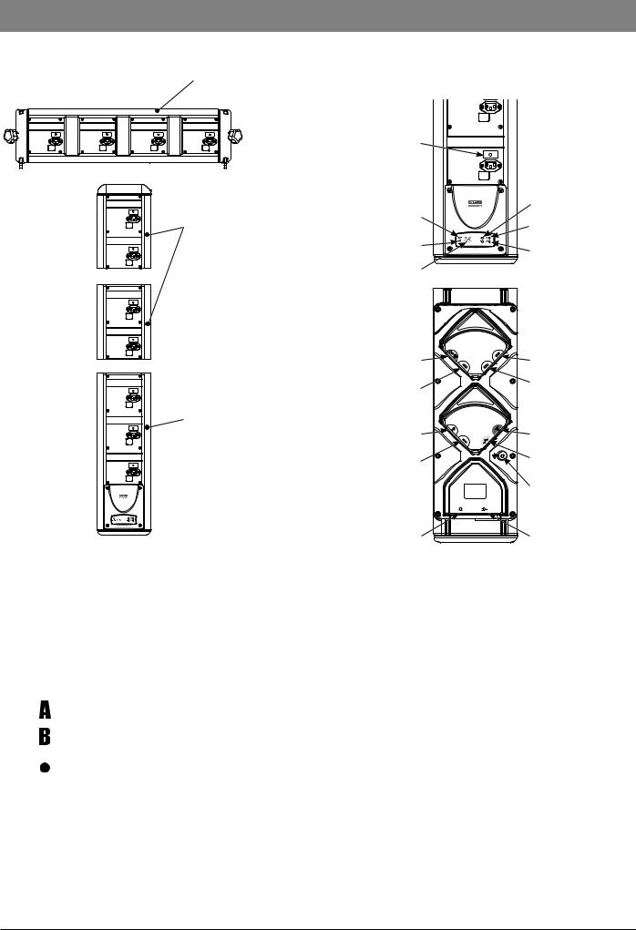
Horizontal 4 tile assembly
3 MDI Tile Base Unit
Front View
Vertical 2 tile assembly
Base Module
Tile Warning |
|
|
|
|
Indicator |
|
|
|
|
|
|
|
|
A/B Status |
Battery |
|
|
|
Indicators |
Indicator |
|
|
|
ON Status |
|
|
|
|
Indicator |
AC Power |
|
|
|
System Fault |
Indicator |
|
|
|
|
ON/OFF |
Rear View |
Indicator |
||
|
||||
Barcode Reader |
|
|
|
RS232 Serial Interface |
|
|
|
|
(optional) |
RS232 Serial Interface |
|
|
|
RS232 Serial Interface |
|
|
|
(optional) |
|
(optional) |
|
|
|
|
|
|
|
|
|
Nurse Call |
|
|
|
Auxiliary |
Interface |
|
|
|
Interface |
Standard RS232 |
|
|
|
Ethernet |
Serial Interface |
|
|
|
Interface |
|
|
|
|
Potential |
|
|
|
|
Equalisation (PE) |
|
115-230V |
|
115-230V |
Connector |
|
~50-60Hz |
AUX |
||
|
350VA |
|
~50-60Hz |
|
|
|
|
|
|
AC Power |
|
|
|
AC Power |
Input |
|
|
|
Output |
a |
ON/OFF Button |
Press once to switch the Workstation on. Press and hold for 1 second to switch |
||
|
the Workstation off. In the event that the system needs to be reset, depress and |
|||
|
hold for at least 4 seconds, then press again to switch the Workstation on. |
|||
|
|
|
|
|
j |
Battery Indicator |
When illuminated the Workstation is operating from the internal battery; when |
||
|
flashing the battery power is depleted. |
|||
|
|
|
|
|
k |
AC Power Indicator |
When illuminated the Workstation is connected to the AC power supply and |
||
|
the battery is being charged. |
|||
|
|
|
|
|
|
|
|
‘A’ Status Indicator |
Provides a visual indication that the software is operational. |
|
|
|
|
|
|
|
|
‘B’ Status Indicator |
Provides a visual indication that the network is operational. |
|
|
|
|
|
|
|
|
‘ON’ Status Indicator |
When illuminated the Workstation is operational. |
|
|
|
||
|
|
|
|
|
|
|
|
|
|
w |
System Fault Indicator |
The Workstation will illuminate this indicator when an internal fault is present |
||
|
and detected. |
|||
|
(Consult accompanying documents for further information). |
|||
|
|
|
|
|
Alaris® Gateway Workstation |
7/67 |
1000SM00015 Issue 4 |
Chapter 2
Routine Maintenance
In this chapter
Required Test Equipment |
9 |
Required Tests |
9 |
Electrical Safety Test |
10 |
Power-up Check |
12 |
Beacon (where fitted) |
12 |
Pump Loading/Removal Checks |
12 |
Battery Test |
13 |
Setting the Time and Date |
14 |
Recommended Cleaning and Inspection |
15 |
Performance Verification Procedure |
16 |

Routine Maintenance
Required Test Equipment
The following test equipment is required to perform the tests in this chapter.
1.Metron QA-90 Medical grade electrical safety tester
2.PC with Ethernet LAN connection, COM port and Internet Explorer 6.0 installed
3.Cat5e Ethernet cable (2m)
4.Cat5e Ethernet Crossover cable (2m)
5.Alaris® Infusion Pump with IrDA enabled which has been serviced within the past 12 months.
6.IEC AC Mains Lead, straight, 134748 (5A)
Required Tests
The following tests are required to test the different Workstation configurations.
|
|
Workstation Configuration |
||
|
Auxiliary |
Workstation |
Workstation with |
|
Functional test |
Workstation |
Wireless LAN |
||
(Option 2) |
||||
|
(Option 1) |
(Option 3) |
||
|
|
|||
Electrical Safety Test |
|
|
|
|
Power-up check |
|
|
|
|
Beacon (when fitted) |
|
|
|
|
Pump Loading/Removal Test |
|
|
|
|
Battery Test |
|
|
|
|
Setting the Time and Date |
|
|
|
|
Alaris® Gateway Workstation |
9/16 |
1000SM00015 Issue 4 |

Routine Maintenance
Electrical Safety Test
The Electrical Safety Test MUST be performed twice.
The first test will ensure the PE and Insulation Resistance are acceptable for safe AC power application.
The second test, with the Workstation on AC power, is to ensure the Leakage Current values are correctly measured.
Electrical Safety Test Calibration
Ensure that no physical contact is made with the unit under test during the electrical safety test cycle.
Connect a Medical grade electrical safety tester, (e.g. Safety Tester) to a main's outlet, ensuring that the connections for Live and Neutral are correct.
1.Connect the enclosure lead to the PE point of the Workstation. Plug the mains test lead from the safety tester into the Workstation mains inlet.
2.Switch on the Workstation.
3.Set up and perform a standard electrical safety test to IEC/EN60601-1 Class I, using an Earth Continuity test current of 25A. If the safety tester requires an applied 'Type' to be entered, select 'Type B' but no applied parts should be specified.
The required test result limits are as follows:
Current Consumption |
<300mA |
Protective Earth Resistance (all test points) |
<100mΩ |
Insulation Resistance |
>200MΩ |
Earth Leakage Current: |
|
Open Supply (OS) |
<1000μA |
Normal Condition (NC) |
<500μA |
Open Supply Reverse Mains (OSRM) |
<1000μA |
Normal Condition Reverse Mains (NCRM) |
<500μA |
Enclosure Leakage Current: |
|
Open Supply (OS) |
<500μA |
Normal Condition (NC) |
<100μA |
Open Earth (OE) |
<500μA |
Open Supply Reverse Mains (OSRM) |
<500μA |
Normal Condition Reverse Mains (NCRM) |
<100μA |
Open Earth Reverse Mains (OERM) |
<500μA |
First Electrical Safety Test
PE Connector - Earth Continuity Test
1.Connect the AC lead from the Safety Tester to the Workstation Mains Inlet.
2.Connect the enclosure lead from the Safety Tester to the PE stud on the rear cover of the Workstation with a crocodile clip.
3.Perform the Earth Continuity Test.
4.Disconnect the enclosure lead from the PE stud.
IEC Mains Outlet Screw/Tile - Earth Continuity Test
1.Apply the free end of the enclosure lead firmly to one of the IEC Mains Outlet screws on the bottom tile.
2.Perform the Earth Continuity Test.
3.Repeat the test for one screw on every IEC Mains Outlet in turn.
4.Repeat the test for one screw on the tile plate.
Alaris® Gateway Workstation |
10/16 |
1000SM00015 Issue 4 |
Routine Maintenance
Electrical Safety Test continued
Tile Module/Mounting Bar - Earth Continuity Test
1.Fit a high current probe to the enclosure lead.
2.Firmly apply the probe point to one of the module tile plate mounting screws.
3.Perform the Earth Continuity Test.
4.Repeat the test for each tile plate mounting screws in turn.
5.Carefully apply the probe point to one end of the tile mounting bar.
6.Perform the Earth Continuity Test.
7.Repeat the test for each tile mounting bar in turn.
Note: Ensure that, in all cases, the resistance to earth of any continuity test DOES NOT exceed 100mΩ.
IEC Outlet Earth Pin - Earth Continuity Test
1.Connect the enclosure lead to the Tile IEC Earth Point.
2.Fit the test equipment to the rear IEC Mains Outlet.
3.Perform the Earth Continuity Test.
4.Repeat the test for each IEC Mains Outlet in turn.
Note: Ensure that, in all cases, the resistance DOES NOT exceed 100mΩ.
Insulation Resistance Test
1.Disconnect the Earth Lead from the Tile IEC and reconnect the enclosure lead to the crocodile clip.
2.Attach the crocodile clip to the PE stud on the rear cover of the Workstation.
3.Perform the Insulation Resistance Test.
Second Electrical Safety Test
Earth and Enclosure Leakage Current Test
Ensure all Earth Continuity Tests and the Insulation Resistance Test results pass before proceeding with the Earth and Enclosure Leakage Current Test.
1.Connect the Safety Tester AC lead to the Workstation Mains Inlet.
2.Ensure that the enclosure lead is connected to the PE stud. Ensure that the Battery Indicator on the front panel keypad is illuminated. If the Battery Indicator is flashing or is not illuminated, the Workstation will require charging for at least 30 minutes before proceeding.
3.On the Safety Tester, conduct a single Earth Continuity Test.
4.Disconnect the Safety Tester from the Workstation.
Alaris® Gateway Workstation |
11/16 |
1000SM00015 Issue 4 |

Routine Maintenance
Power-up Check
This test checks that the speaker and the keypad LEDs are operating correctly after power-up.
1.Observing the front panel keypad, connect the Workstation to the AC Mains supply using an IEC Mains Lead and ensure that the AC Power Indicator is illuminated.
2.Switch the Workstation on using the ON/OFF button.
3.Check that the 'ON' Status indicator is illuminated, the System Fault indicator flashes rapidly and the secondary speaker produces a beep. After a few seconds, the primary speaker, situated at the rear of the Workstation, will produce a tone.
4.The secondary speaker will then buzz for 1 second followed by a 1 second tone from the primary speaker.
5.The 'A' Status indicator will start flashing once per second.
6.After 30 seconds, the 'B' Status indicator will flash approximately once every 30 seconds.
Beacon (where fitted)
This test checks that the Beacon is working correctly.
1.Connect the Workstation to the AC Mains supply using an IEC Mains Lead and ensure that the AC Power Indicator is illuminated.
2.Observing the end Beacon, switch the Workstation on using the ON/OFF button.
3.Check the red LED on the Beacon glows dimly.
4.Check that the red LED on the beacon flashes brightly and then dims.
5.Check that the amber LED on the beacon flashes brightly and then dims.
6.No more beacon activity should occur unless a pump is alarming.
Pump Loading/Removal Checks
Connect the Workstation to the AC Mains supply using an IEC Mains Lead and ensure that the AC Power Indicator is illuminated. Load pump to each tile in turn and check:
•Pump is properly located on its electrical connectors
•Pump is mechanically locked into position
•Pump mains indicator turns on when fully fitted
When removing the pump from the tile check:
•Pump mains indicator turns off
•Check that the red LED on the tile turns OFF when the pump is removed. If the LED stays ON, the Workstation should be serviced by a qualified service engineer.
Alaris® Gateway Workstation |
12/16 |
1000SM00015 Issue 4 |
Routine Maintenance
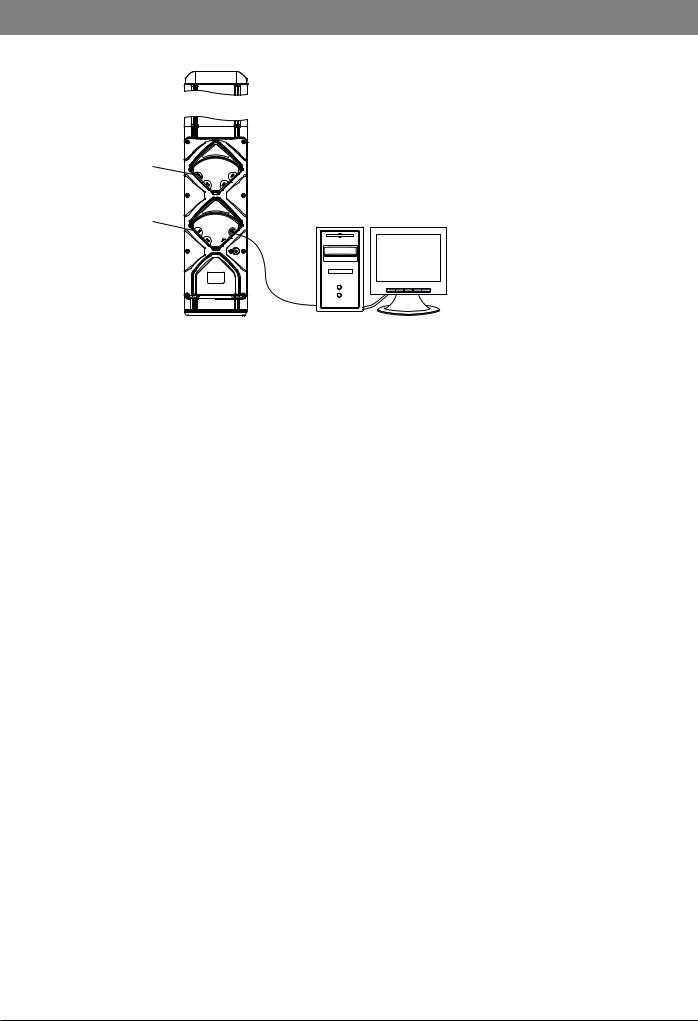
Battery Test
This test verifies that the battery is functioning correctly, with and without AC mains attached to the Workstation:
Barcode Reader
Connector
Nurse Call
Connector
Rear View of |
Cat5e Ethernet |
Test PC |
Workstation |
Crossover Cable |
with Wireless LAN card |
1.Connect the Workstation to the test equipment as shown. Connect Workstation to AC mains using IEC Mains Lead.
2.Connect the Cat5e crossover cable between the Auxiliary Connector port on the rear of the Workstation and the test PC ethernet port.
3.Switch on the Workstation. Wait for the Workstation to initialise (approx. 45 seconds).
4.Manually set the test PC's IP address to 192.168.0.130, Subnet mask 255.255.255.0.
5.On the Test PC, launch Internet Explorer. In the address bar at the top of the screen enter the following address: http://192.168.0.128
6.Confirm that the Workstation web service startup page is displayed. Click the Refresh icon and confirm that the startup page continues to be displayed when the refresh is complete.
7.Click OK on the startup screen.
8.Check that, at the bottom right hand corner of the monitoring page on the test PC, the battery symbol shows a capacity percentage of between 5% and 100%. If the capacity is less than 5% then the Workstation must remain connected to AC mains until the capacity reaches 50%.
9.Remove the AC mains lead and ensure that the Workstation continues to operate and shows a capacity percentage of between 5% and 100%. If the unit does not operate or shows a percentage less than 5% then it is likely that a battery sub-system fault has
Alaris® Gateway Workstation |
13/16 |
1000SM00015 Issue 4 |

Routine Maintenance
Setting the Time and Date
1.Ensure that the Cat5e crossover cable between the Auxiliary Connector port on the rear of the Workstation and the test PC ethernet port.
2.Connect the Workstation to AC mains using an IEC Mains Lead. Switch on the Workstation.
3.Manually set the test PC's IP address to 192.168.0.130, Subnet mask 255.255.255.0.
4.On the Test PC, launch Internet Explorer. In the address bar at the top of the screen enter the following address: http://192.168.0.128
5.Click OK on the startup screen. Confirm that the tile monitoring page is displayed.
6.Click on Date & Time in the navigation panel on the left of the screen. The following screen is displayed:
7.Enter the correct date and correct time .
8.Click Update to confirm.
9.Click on Event Logs in the navigation panel on the left of the screen. An entry for Time Changed and Date Changed at the bottom of the list indicates that the time and date have been updated successfully.
Alaris® Gateway Workstation |
14/16 |
1000SM00015 Issue 4 |

Routine Maintenance
Recommended Cleaning and Inspection
Cleaning the Workstation: -
Before the transfer of the Workstation to a new patient and periodically during the use, clean the Workstation by wiping over with a lint-free cloth lightly dampened with warm water and a standard disinfectant / detergent solution.
Recommended cleaners are:
Brand |
Concentration |
Hibiscrub |
20% (v/v) |
Virkon |
1% (w/v) |
Do not use the following disinfectant types:
-NaDcc (such as PRESEPT)
-Hypochlorites (such as CHLORASOL)
-Aldehydes (such as CIDEX)
-Cationic Surfactants (such as Benzalkonium Chloride)
-Iodine (such as Betadine)
-Concentrated Isopropyl alcohol based cleaners will degrade plastic parts.
Before cleaning always switch OFF and disconnect from the AC power supply.
Never allow fluid to enter the casing and avoid excess fluid build up on the pump.
Do not use aggressive cleaning agents as these may damage the exterior surface of the Workstation.
Do not steam autoclave, ethylene oxide sterilise or immerse this Workstation in any fluid.
To ensure that this Workstation remains in good operating condition, it is important to keep it clean and carry out the routine maintenance procedures described below.
Interval |
Routine Maintenance Procedure |
When loading pumps |
Check that each pump is properly located on its electrical connectors and is mechanically locked into position. |
When removing pumps |
Check that the red LED turns OFF on the Tile Plate when the pump is removed. If the LED stays ON, the |
|
Workstation should be serviced by a qualified service engineer. |
As required |
Thoroughly clean external surfaces of the equipment before and after prolonged periods of storage. |
12 Monthly |
Inspect AC outlets, communication connectors and the AC inlet for damage. |
|
Perform electrical safety checks. The complete unit leakage current must be measured. If more than 500μA the |
|
equipment should not be used, but should be serviced by a qualified service engineer. |
Alaris® Gateway Workstation |
15/16 |
1000SM00015 Issue 4 |

|
Routine Maintenance |
|
|||
|
|
|
|
|
|
Performance Verification Procedure |
|
|
|
|
|
|
|
|
|
|
|
|
|
|
|
||
Model / Serial Number: |
Service Order / Inventory Number: |
|
|||
|
|
|
|
||
Hospital Name / Reference: |
|
Software Version: |
|
||
|
|
|
|
|
|
INSPECTION |
Physical inspection and clean |
|
|
|
|
|
|
|
|
|
|
OPERATION CH2 |
Power-up Check |
|
|
|
|
|
Ensure that the speaker and Keypad LEDs are functioning correctly. |
|
|||
|
Check Beacon operation (if fitted). |
|
|
|
|
|
Pump Removal/Loading Checks |
|
|
|
|
|
Battery Test |
|
|
|
|
|
|
|
|
|
|
SETUP CH2 |
Set the correct Date and Time. |
|
|
|
|
|
|
|
|
|
|
|
Class I (no applied parts) |
|
|
|
|
|
Perform tests with no pumps attached |
|
|
|
|
ELECTRICAL |
Earth Resistance Test <= 200mΩ |
|
|
|
|
|
|
|
|
|
|
SAFETY TESTS CH2 |
Earth Leakage Current <= 500 μA |
|
|
|
|
|
Enclosure Leakage Current <= 100 μA |
|
|
|
|
|
attach printed test results |
|
|
|
|
Verification |
|
|
|
|
|
Performed |
_______________________________ |
_____________________________ |
|
__________________________ |
|
By |
|
||||
|
Sign |
|
Date |
||
CHX indicates the chapter number in the Technical Service Manual (TSM) - 1000SM00015.
E.G. CH2 = Refer to TSM Chapter 3.
Alaris® Gateway Workstation |
16/16 |
1000SM00015 Issue 4 |
Chapter 3
Troubleshooting
In this chapter
Troubleshooting Guide |
18 |

Troubleshooting
Troubleshooting Guide
Warnings
Use extreme caution when servicing equipment whilst it is connected to the AC mains.
This equipment contains static-sensitive components. Wherever the ESD symbol V appears observe strict precautions for the protection of static-sensitive components when attempting to service and repair the equipment.
Always visually inspect the tiles, communications cables and connectors, power cord and plug for damage. If the power cord or plug are damaged they should be replaced.
Should further technical assistance be required call your local Cardinal Health Service Centre.
Workstation has been Dropped or Damaged
If the equipment is damaged, the damaged parts should be identified and replaced before any further troubleshooting is carried out.
During inspection, careful attention should be paid to the power tile and each docking tile, which may be damaged if the docking station is dropped.
Workstation has been Exposed to Fluids
Excessive fluid spills can lead to fluid ingress into the docking station. Even if the fluid dries out, deposits can be left which cause the equipment to fail.
If fluid ingress is suspected the docking station should be inspected internally.
Clean and dry out the equipment.
Take care to ensure dried out deposits do not remain on the PCBs or other electrical components. Replace permanently damaged tiles.
Workstation Will Not Power from AC Supply
First check the function of the AC power cable with another piece of working equipment.
Check that the AC power is switched on at the outlet, if applicable.
Check that the power cord is seated properly in the AC power inlet. Also check the fuse in the AC power plug.
If the AC Power switch does not illuminate when the pump is connected to a live AC cable, check the fuses at the AC power inlet.
Power Not Present at Pump
Check that the docking station is switched on and has power.
Check that the pump is correctly seated on the tile.
Hold a magnet next to the Infra-Red communications port on the tile. If the Warning LED does not light up the tile must be replaced. If the LED does light up, suspect a problem with the pump and remove from service to be examined by qualified service personnel.
Warning LED Remains Lit when Pump is Removed from Tile
Replace the complete tile, following the instructions in chapter 5 'Spare Parts Replacement Procedures'.
Alaris® Gateway Workstation |
18/67 |
1000SM00015 Issue 4 |
Chapter 4
Circuit Descriptions
In this chapter
Functional Module Block Diagram |
20 |
Module Overview Functional Description |
21 |

Circuit Descriptions
Functional Module Block Diagram
The Alaris® Gateway Workstation
The Workstation has been designed as a modular system providing a communications gateway between the Alaris® Infusion Pump and any Patient Data Management System (PDMS), Patient Monitoring (PM) System or Clinical Information System (CIS) that requires access to the infusion data retained within the pump.
The device supports optional upgrades to enhance the data communication interfaces and to support software for connections to such client / server systems.
The user can access data and configure software installed on the Workstation from a client PC using a standard Web browser; this may be performed over an Ethernet network or by directly linking to the Workstation.
The software is provided under license from Cardinal Health, Inc.
Feature Summary
•Central management system for multiple Alaris® Infusion Pumps
•Medical Device Interface – a unique mounting mechanism proving data communications and mains power to the Alaris® Infusion Pump
•Reduced cable clutter with the use of a single AC power inlet
•Simple to set up with adaptable modular design
•Efficient organisation of multiple infusion lines and configurations
•Battery back-up in the event of power supply interruption
•High visibility beacon assists with the location of pumps in an alarm state (where fitted)
•Nurse call interface for all Alaris® Infusion Pumps attached to the Workstation
•Software running on the Workstation allows remote access to the device
Electronics Architecture |
|
|
|
|
|
|
|
|
|
The Alaris® Gateway Workstation |
|
|
|
|
|
|
|
|
|
Key |
|
|
Services Board PCB* |
|
|
J2 |
RS232 Serial Port - Com2** |
||
|
|
|
|
|
|
||||
Data Lines |
|
|
|
|
|
|
|
||
|
|
|
|
|
4 Port RS232 |
|
RS232 Serial Port - Com3** |
||
Power Lines |
|
|
Quad UART |
J4 |
J1 |
J3 |
|||
Combination |
|
|
Serial Isolation |
|
|
||||
|
|
|
|
|
|||||
|
|
|
Internal |
|
|
PCB** |
J4 |
RS232 Serial Port - Com4** |
|
* Available as a User Option |
|
J7 |
|
|
|||||
|
|
|
|
|
|||||
|
USB 1 |
|
|
|
|
|
|||
** Not available at time of initial release |
|
|
|
|
|
RS232 Serial Port - Com5** |
|||
|
|
|
|
|
J5 |
||||
|
|
|
Internal |
J10 |
|
|
|||
|
|
|
|
|
|
|
|||
|
|
|
USB 2 |
|
|
|
|
|
|
|
|
|
|
|
|
|
|
|
|
|
|
|
PCMCIA |
J8 |
CiscoAIR-LMC 352* |
|
CiscoAIR-ANT4941* |
|
|
|
|
|
|
|
|
|
|
||
Expansion |
J5 |
J5 |
Audio (Mono) |
J11 |
|
|
|
Speaker |
|
|
|
|
|
|
|||||
Expansion |
J6 |
J6 |
LVDS |
J13 |
|
|
|
Colour LCD Display with |
|
Display |
|
|
|
||||||
|
|
|
|
|
|
|
|||
LVDS |
J3 |
J14 |
UART 1 |
J12 |
|
|
|
Resistive Touchscreen** |
|
|
|
|
|
|
|||||
Display |
|
|
|
|
|
||||
|
|
|
|
|
|
|
|
|
|
Compact |
J1 |
|
Barcode |
J15 |
|
|
|
Barcode Reader* |
|
Flash |
|
Reader |
|
|
|
|
|
||
|
|
|
|
|
|
|
|
||
AA1100 |
|
|
Isolated |
J14 |
|
|
|
RS232 Serial Port - Com1 |
|
|
|
RS232 |
|
|
|
||||
Single Board Computer* |
|
|
|
|
|
|
|
||
|
Isolated |
|
|
|
|
|
|
||
|
|
|
J3 |
J1 |
|
J2 |
External Network RJ45 |
||
|
|
|
Ethernet |
|
|
|
|||
128MByte CF Card* |
|
|
|
|
|
|
|
|
|
|
|
|
|
|
|
J5 |
Nurse Call Interface |
|
|
|
|
|
|
|
|
|
|
||
|
|
|
|
|
|
|
|
|
|
|
|
|
|
|
|
Ethernet |
J4 |
Auxiliary Gateway RJ45 |
|
|
|
|
|
|
|
Isolation PCB* |
|
|
|
|
|
|
|
|
|
|
J6 |
|
|
|
|
|
Internal |
J9 |
|
|
J3 |
|
|
|
|
|
Network |
|
|
|
|
||
|
|
|
|
|
|
|
|
|
|
|
|
|
|
J1 |
J2 |
Internal |
J3 |
|
|
|
|
|
|
|
Network |
|
|
||
|
|
|
|
|
|
|
|
|
|
Keypad / Status LEDs |
|
|
|
J2 |
|
Nurse Call |
J5 |
|
|
|
|
|
|
|
|
|
|||
|
|
|
|
|
|
|
|
||
Battery Pack |
|
J2 |
Power |
J4 |
|
|
J13 |
Visual Status Indicator |
|
|
|
|
|
|
|
||||
Power and |
J1 |
|
|
|
|
|
|
AC Power to Pumps |
|
Control |
J6 |
LVPS Control |
J3 |
|
|
|
|
||
|
|
|
|
|
|||||
|
|
|
|
|
|
||||
+15v Power |
J1 |
J6 |
Power |
J5 |
J1 |
Tile PCB |
|
IrDA Interface to Pumps |
|
|
|
|
|
||||||
Mains Power |
J1 |
|
|
|
|
|
|
|
|
Power Supply Unit |
|
|
|
|
|
|
|
Mains |
Mains |
|
|
|
|
|
|
|
Inlet |
Outlet |
|
|
|
|
|
|
|
|
|
||
Alaris® Gateway Workstation |
|
|
|
20/67 |
|
|
|
1000SM00015 Issue 4 |
|
Circuit Descriptions
Module Overview Functional Description
Services Board and Single Board Computer
The Single Board Computer (SBC) is an off the shelf processor board supplied to Cardinal Health, Inc. by DSP Designs. The SBC connects both mechanically and electrically to the Services Board PCB which provides the processor with the peripheral external interfaces. The SBC also contains the 128 MByte Compact Flash card. Also available on the Services Board is a PCMCIA connector into which attaches the Cisco wireless card and antenna.
Low Voltage Power System Board
The Low Voltage Power System Board (LVPS) provides the Workstation with low voltage DC power. The LVPS Board gets power from the PSU module connected to the AC mains supply. A smart rechargeable battery pack is connected to the LVPS Board as a second power source used when the AC mains is unavailable; this makes the LVPS Board act as a UPS.
The LVPS Board has an on-board charger that is responsible for keeping the smart battery pack charged. The LVPS Board provides regulated 3.3V and 5V to the Services Board and also provides either +15V from the power supply or battery terminal voltage to the Tile Boards. The circuitry for switching on and off the Docking Station is on the LVPS Board, which the User activates with an externally mounted keypad.
Tile Board
In the Workstation the Tile Board provides the interface to the pumps providing power (directly from the AC mains) and an IrDA port for communication with the pumps. The Tile board itself communicates via the Internal Switched Ethernet to the SBC. The Tile board also controls the Visual Status Indicator and Nurse Call interface directly without the need for the SBC to be fitted.
The Tile Board is designed in four different configurations:
•Vertical mount, two tiles high
•Vertical mount, three tiles high
•Horizontal mount, two tiles wide
•Horizontal mount, three tiles wide
To enable the modular construction, Tile Boards connect in series to extend the number of tiles within the Workstation as the configuration shape grows.
Ethernet Isolation Board
The function of the Ethernet Isolation Board is to provide electrical separation between the internal electronics of the Workstation and the external Ethernet connections. This board isolates both the primary 10 Base T / 100 Base-Tx interface and also the Ethernet connection with an Auxiliary Docking Station. The board also provides the relay for the nurse call function.
Power Supply Unit
The Power Supply Unit (PSU) converts AC mains voltage into +15VDC used to power all electronic sub-systems within the Workstation when AC mains is connected. The AC mains input is implemented as a spur off the Live and Neutral wiring within the device that also provides AC mains power to the pumps and to the AC mains outlet connector.
Battery Pack
A 9.6v, 2.7A internal battery provides a UPS function should a temporary disconnection from the AC mains power supply occur. The NiMH battery pack includes a gas gauge and supports the SMB interface.
Alaris® Gateway Workstation |
21/67 |
1000SM00015 Issue 4 |
 Loading...