


Alaris®GH Syringe Pump
Directions For Use - English

|
|
Contents |
|
|
Page |
|
Introduction................................................................................................................. |
...................... 2 |
|
About This Manual ............................................................................................................ |
................ 2 |
|
Quick Start Guide ............................................................................................................ |
.................. 2 |
|
Features of the Alaris® GH Syringe Pump...................................................................................... |
.. 3 |
|
Controls & Indicators........................................................................................................ |
................. 4 |
|
Symbol Definitions........................................................................................................... |
................. 5 |
|
Main Display Features........................................................................................................ |
............... 6 |
|
Operating Precautions........................................................................................................ |
.............. 7 |
|
Getting Started.............................................................................................................. |
.................... 9 |
|
Basic Features ............................................................................................................... |
..................... 13 |
|
Alarms and Warnings .......................................................................................................... |
.............. 16 |
|
Configured Options........................................................................................................... |
................ 17 |
|
Specifications............................................................................................................... |
...................... 20 |
|
Compatible Syringes ......................................................................................................... |
............... 21 |
|
Associated Products ......................................................................................................... |
................ 21 |
|
Compatible Extension Sets ................................................................................................... |
........... 22 |
|
Maintenance .................................................................................................................. |
.................... 24 |
|
Occlusion Pressure Limits ................................................................................................... |
............. 26 |
|
IrDA, RS232 and Nurse call Specification ..................................................................................... |
... 27 |
|
Trumpet Curves & Start-up Curves ............................................................................................. |
..... 28 |
|
Products and Spare Parts...................................................................................................... |
............ 29 |
|
Service Contacts ............................................................................................................ |
................... 30 |
|
Document History ............................................................................................................. |
................ 30 |
|
Warranty .................................................................................................................... |
........................ 31 |
|
Index ........................................................................................................................ |
........................... 32 |
1000DF00002 Iss. 2 |
1/32 |

Introduction
The Alaris® GH Syringe Pump (herein after referred to as "pump") is a fully featured syringe pump suitable for critical care and general infusion applications.
Intended Use:
The pump is designed to meet the infusion requirements within the operating environment specified in this Directions For Use (DFU) including general wards, critical and intensive care, neonatal, operating rooms and accident and emergency rooms.
This pump is suitable for use by appropriately trained clinicians or nurses. The syringe pump is suitable to deliver fluids and medications via intravenous routes. Supporting fluid therapy, blood transfusions and parenteral feeding.
The Asena® brand name has been recently changed to the Alaris® brand name. This change in brand name has no effect on the intended use or functionality of the product. Recommended disposable products for use with this product may refer to either the Asena® brand name or Alaris® brand name and both types are suitable for use with this infusion pump.
The Alaris® GH Syringe Pump is compatible with a wide range of standard, single-use, disposable Luer-lock syringes. It accepts syringe sizes from 5 ml to 50 ml. See the 'Compatible Syringes' section for a full list of compatible syringes.
Simple to set up and easy to operate.
Large graphics format display.
Medical Device Interface (MDI) - a unique mounting mechanism.
Rate Range from 0.1 to 1200ml/h.
Event logging records operation of pump.
Advanced Communications and Nurse call interfaces.
Configurable drug names.
About This Manual
The user must be thoroughly familiar with the Alaris® GH Syringe Pump described in this manual prior to use.
All illustrations used in this manual show typical settings and values which may be used in setting up the functions of the pump. These settings and values are for illustrative use only. Where stated, a minimum infusion rate refers to a nominal rate of 1.0ml/h, and an intermediate infusion rate refers to a nominal rate of 5.0ml/h. The complete range of infusion rates, settings and values are shown in the Specifications section.
Quick Start Guide
1.Press the abutton to turn the pump on.
2.CLEAR SETUP? - NO retains previous data. YES clears previous data.
3.Load syringe.
4.Confirm correct size and brand of syringe.
5.Ensure extension set is attached to syringe, but disconnected from patient.
If the PURGE SYRINGE option has been enabled then the prompt to purge screen is displayed and the set can be purged as required.
6.INFUSION RATE - Change rate if necessary using the fkeys.
7.PURGE - Press the ibutton followed by the PURGE softkey.
8.Connect extension set to the patient access device.
9.Press the bbutton to start the infusion.
1000DF00002 Iss. 2 |
2/32 |

Features of the Alaris® GH Syringe Pump
ON/OFF |
Display |
Release lever for |
High visibility |
RUN |
MDI |
Alarm Indicator |
PURGE/
BOLUS
MUTE
PRESSURE
OPTION
Finger
Grips
Extension |
HOLD |
Shelf for chevron |
Syringe Clamp |
Positive Plunger |
set hook |
|
keys and softkeys |
|
Grippers |
Rating Plate (see Symbol Definitions for an explanation of the symbols used)
Release lever for Rotating Cam
Medical Device
Rotating Cam to lock on to horizontal
rectangular bars IR Communications port
I
nter
fa
ce
(
M
D
I
)
Carrying |
Potential |
Folded Pole |
RS232 |
Extension set |
Handle |
Equalisation |
Clamp |
Connector |
hook |
|
(PE) connector |
|
(optional) |
|
1000DF00002 Iss. 2 |
3/32 |

|
|
Controls & Indicators |
Controls: |
|
|
|
|
|
Symbol |
Description |
|
|
|
|
a |
ON/OFF button - Press once to switch the pump ON. Press and hold down for 3 |
|
seconds to switch the pump OFF. |
||
|
|
|
b |
RUN button - Press to start the infusion. The green LED will flash during infusion. |
|
|
|
|
h |
HOLD button - Press to put the infusion on hold. The amber LED will be lit while on |
|
hold. |
|
|
|
|
|
c |
MUTE button - Press to silence alarm for 2 minutes (configurable). Press and hold |
|
until 3 beeps are heard for 15 minutes silence. |
||
|
|
|
|
PURGE/BOLUS button - Press to access PURGE or BOLUS soft keys. Press and hold |
|
|
down soft key to operate. |
|
|
PURGE the extension set during set up. |
|
|
Pump is on hold |
|
i |
Extension set is not connected to the patient |
|
Volume Infused (VI) is not added |
||
|
BOLUS - fluid or drug delivered at an accelerated rate. |
|
|
|
Pump is infusing |
|
Extension set is connected to the patient |
|
|
|
VI is added |
|
|
|
d |
OPTION button - Press to access optional features (see Basic Features). |
|
|
|
|
e |
PRESSURE button - Use this button to display the pumping pressure and alarm |
|
level. |
|
|
|
|
|
f |
CHEVRON keys - Double or single for faster/slower increase or decrease of values |
|
shown on display. |
||
|
|
|
g |
BLANK SOFTKEYS - Use in conjunction with the prompts shown on the display. |
|
|
|
|
Indicators: |
|
|
|
|
|
Symbol |
Description |
|
|
|
|
j |
BATTERY indicator - When illuminated the pump is running on the internal battery. |
|
When flashing the battery power is low with less than 30 minutes of use remaining. |
||
|
|
|
S |
AC POWER indicator - When illuminated the pump is connected to an AC power |
|
supply and the battery is being charged. |
||
|
|
|
1000DF00002 Iss. 2 |
4/32 |

|
Symbol Definitions |
Labelling Symbols: |
|
|
|
Symbol |
Description |
w |
Attention (Consult accompanying documents) |
|
|
x |
Potential Equalisation (PE) Connector |
|
|
y |
RS232/Nurse call Connector (Optional) |
|
|
|
Defibrillation-proof type CF applied part (Degree of protection against electrical |
shock) |
|
|
|
O |
Protected against vertically falling drops of water |
|
|
r |
Alternating Current |
|
|
s |
Device complies with the requirements of the EC Directive 93/42/EEC. Registered |
with the CE Mark. |
|
|
|
T |
Date of Manufacture |
|
|
t |
Manufacturer |
|
|
U |
Not for Municipal Waste |
|
|
A |
Important information |
|
|
W |
Fuse Rating |
|
|
1000DF00002 Iss. 2 |
5/32 |
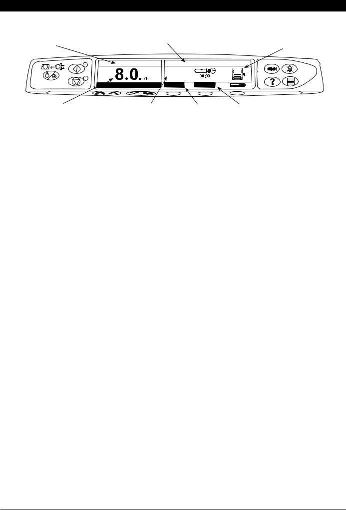
Main Display Features
Pump |
Syringe type fitted / |
|
Drug name |
|
|
Status |
|
|
|
|
|
|
ON HOLD |
VOLUME |
|
|
|
|
|
0.0ml |
+ |
ADJUST - |
VOLUME |
Pressure
Information
IVAC 50
VTBI
|
Infusion |
Volume |
Volume Infused |
VTBI |
|
|
Rate |
Infused |
Option |
Option |
|
Screen Icons: |
|
|
|
|
|
|
|
|
|
|
|
Symbol |
|
Description |
|
|
|
|
|
|
|||
l |
TIME REMAINING DISPLAY icon |
- Indicates time before syringe will require replacing. |
|||
|
|
||||
N |
BATTERY icon - Indicates battery charge level to highlight when the battery will require recharging. |
||||
|
|
|
|
|
|
1000DF00002 Iss. 2 |
6/32 |

|
Operating Precautions |
|
Disposable Syringes and Extension Sets |
m |
• This Alaris® GH Syringe Pump has been calibrated for use with single-use disposable syringes. To ensure |
correct and accurate operation, only use 3 piece Luer-Lock versions of the syringe make specified on |
|
|
the pump or described in this manual. Use of non-specified syringes or extension sets may impair the |
|
operation of the pump and the accuracy of the infusion. |
n |
• Uncontrolled flow or syphoning may result if the syringe is located incorrectly in the pump, or if it is |
removed from the pump before the extension set is properly isolated from the patient. Isolation may |
|
include closing a tap in the patient line or activating a flow stop clamp. |
|
o |
• Secure the extension set to the pump using the extension set hook at the rear of the pump. This provides |
protection against accidental dislodging of the syringe from the pump. |
G
H I
•When combining several apparatus and/or instruments with extension sets and other tubing, for example via a 3-way tap, the performance of the pump may be impacted and should be monitored closely.
Mounting the Pump
•The pump must be mounted within 1.0m above or below the patient’s heart. The most accurate pressure monitoring in the extension set is achieved when the pump is positioned close to the patients heart level.
•Do not mount the pump in a vertical position with the syringe pointing upwards as this could lead to
an infusion of air which may be in the syringe. To protect against the introduction of air the user should regularly monitor the progress of the infusion, syringe, extension line and patient connections and follow the priming procedure specified herein.
Operating Environment
• When using any infusion pump in conjunction with other pumps or devices requiring vascular access, extra care is advised. Adverse delivery of medication or fluids can be caused by the substantial variation in pressures created within the local vascular system by such pumps. Typical examples of those pumps are used during dialysis, bypass or cardiac assist applications.
• This pump is suitable for use in Hospital and clinical environments other than domestic establishments and those directly connected to the public single phase AC mains power supply network that supplies buildings used for domestic purposes. However, it may be used in domestic establishments under the supervision of Medical professionals with additional necessary appropriate measures. (Consult Technical Service Manual, appropriately trained technical personnel or Cardinal Health for further information).
• This pump is not intended to be used in the presence of a flammable anaesthetic mixture with air or oxygen or nitrous oxide.
|
Operating Pressure |
|
• This is a positive pressure pump designed to achieve very accurate fluid administration by automatically |
|
compensating for resistance encountered in the infusion system. |
|
• The pumping pressure alarm system is not designed to provide protection against, or detection of, IV |
|
complications which can occur. |
|
Alarm Conditions |
J |
• Several alarm conditions detected by this pump will stop the infusion and generate visual and audible |
alarms. Users must perform regular checks to ensure that the infusion is progressing correctly and no |
|
alarms are operating. |
1000DF00002 Iss. 2 |
7/32 |

|
Operating Precautions (continued) |
|
Electromagnetic Compatibility & Interference |
M |
• This pump is protected against the effects of external interference, including high energy radio frequency |
emissions, magnetic fields and electrostatic discharge (for example, as generated by electrosurgical and |
|
cauterising equipment, large motors, portable radios, cellular telephones etc.) and is designed to remain |
|
|
safe when unreasonable levels of interference are encountered. |
|
• This pump is a CISPR 11 Group 1 Class A device and uses RF energy only for its internal function in the normal |
|
product offering. Therefore, its RF emissions are very low and are not likely to cause any interference with |
|
the nearby electronic equipment. However, this pump emits a certain level of electromagnetic radiation |
|
which is within the levels specified by IEC/EN60601-1-2 and IEC/EN60601-2-24. If the pump interacts with |
|
other equipment, measures should be taken to minimise the effects, for instance by repositioning or |
|
relocation. |
|
• In some circumstances the pump may be affected by an electrostatic discharge through air at levels close |
|
to or above 15kv; or by radio frequency radiation close to or above 10v/m. If the pump is affected by |
K |
this external interference the pump will remain in a safe mode; the pump will duly stop the infusion and |
alert the user by generating a combination of visual and audible alarms. Should any encountered alarm |
|
|
condition persist even after user intervention, it is recommended to replace that particular pump and |
|
quarantine the pump for the attention of appropriately trained technical personnel. (Consult Technical |
|
Service Manual for further information). |
|
Hazards |
B |
• An explosion hazard exists if the pump is used in the presence of flammable anaesthetics. Exercise care to |
locate the pump away from any such hazardous sources. |
|
A |
• Dangerous Voltage: An electrical shock hazard exists if the pump’s casing is opened or removed. Refer all |
servicing to qualified service personnel. |
•When connected to an external power source, a three-wire (Live, Neutral, Earth) supply must be used. If the integrity of the external protective conductor in the installation or its arrangement is in doubt, the pump should be operated from the battery.
•Do not open the RS232/Nurse Call protective covering when not in use. Electrostatic discharge
V |
(ESD) precautions are required when connecting RS232/Nurse Call. Touching the pins of the |
connectors may result in ESD protection failure. It is recommended that all actions must be taken by |
|
|
appropriately trained personnel. |
•If this pump is dropped, subjected to excessive moisture, fluid spillage, humidity or high temperature, or
otherwise suspected to have been damaged, remove it from service for inspection by a qualified service L engineer. When transporting or storing the pump, use original packaging where possible, and adhere to temperature, humidity and pressure ranges stated in the Specifications section and on the outer
packaging.
Latex Content
•The Alaris® GH Syringe Pump does not contain any Latex.
1000DF00002 Iss. 2 |
8/32 |

Getting Started
Initial Set-up
A Before operating the pump read this Directions For Use manual carefully.
1.Check that the pump is complete, undamaged and that the voltage rating specified on the label is compatible with your AC power supply.
2.Items supplied are:
Alaris® GH Syringe Pump
User Support CD (Directions For Use)
AC Power Cable (as requested)
Protective Packaging
3.Connect the pump to the AC power supply for at least 2½ hours to ensure that the internal battery is charged (verify that the Sis lit).
Language Selection
1.On initial start-up the pump will display the Select Language screen.
2.Select the required language from the list displayed using the f keys.
3.Press the OK softkey to confirm your selection.
A The pump will automatically operate from its internal battery if the pump is switched on without being connected to the AC power supply.
Should the pump fail to perform correctly, replace in its original protective packaging, where possible and contact a qualified service engineer for investigation.
1000DF00002 Iss. 2 |
9/32 |
Getting Started (continued)
A Do not mount the pump with the AC power inlet or the syringe pointing upwards. This could affect the electrical safety in the event of a fluid spill or lead to the infusion of air which may be in the syringe.
Pole Clamp Installation
The pole clamp is fitted to the rear of the pump and will provide secure fixing to vertical I.V. poles of a diameter between 15 and 40 mm.
Recessed area
1.Pull the folded pole clamp towards you and unscrew the clamp to
leave enough room for the size of the pole.
2. Place pump around pole and tighten screw until the clamp is secured to the pole.
A |
* |
* |
Ensure the pole clamp is folded away and stored |
|
|
within the recessed area at the rear of the |
|
|
pump before connecting to a Docking Station/ |
|
|
Workstation* or when not in use. |
|
Never mount the pump such that the IV infusion stand becomes top heavy or unstable.
Docking Station/Workstation* or Equipment Rail Installation
Rectangular bar |
Release lever (push to release) |
Rotating cam
The rotating cam can be fitted to the rectangular bar on the Docking Station/Workstation* or the equipment rail measuring 10 by 25 mm.
1.Align the rotating cam on the rear of the pump with the rectangular bar on the Docking Station/Workstation* or the equipment rail.
2.Hold the pump horizontally, push the pump firmly onto the rectangular bar or equipment rail.
Ensure that the pump 'clicks' securely into position onto the bar.
3.To release, push the release lever and pull the pump forwards.
*Alaris® DS Docking Station, Asena® IDS Docking Station, and Alaris® Gateway Workstation.
1000DF00002 Iss. 2 |
10/32 |
 Loading...