

Page 1
Page 2
Warning
Power requirements
Power requirements fo r electrical equipment differ from area to area.
Please ensure that your mac hine meets the power requirements in your
area. If in doubt, consult a qualified electrician. 120 V, 60 Hz fo r U SA
and Canada 220 V. 50 Hz for Europe except UK 240 V, 50 Hz for UK and
Australia 1 10 V/120 V/220 V/240 V, 50/60 Hz c o nvertible for other
coutries.
Voltage conversion
Models for Canada, USA, Europe, UK and Australia are not equipped with
this facility. Each machine is preset at the factory according to its
destination, but some machines can be set to 110 V, 120 V, 220 V or
240 V as required. If your machine's voltage can be converted: Before
connecting the power cord, turn the VOLTAGE SELECTOR located on the
beneath the sidewooden panel (right hand side) with a screwdriver until
the correct voltage is indicated.
Precautions
FOR CUSTOMERS
IN THE UK
IMPORTANT FOR YOUR, SAFETY
The flex supplied with your machine will have either two wires or three,
as shown in the illustrations.
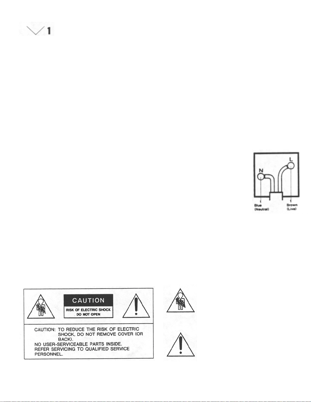
TWO CORE FLEX
IMPORTANT
The wires in this mains lead are coloured in
accordance with the following code:
Blue: Neutral
Brown: Live
As the colo u rs of th e wir e s in th e ma in s lea d
of this apparatus may not correspond with
the coloured markings indentifying the
termina ls in your plug, proceed a s follows:
The wire which is coloured blue must be
connected to the terminal which is marked
with the letter N or coloured black.
This equipment conforms to EEC standa rd No. 82/499.
The wire which is coloured brown must be
connected to the terminal which is marked
with the letter L or coloured red.
Do not connect any wire to the larger pin marked E or -= when
wiring a plug. Ensure that all terminals are securely tightened and
that no loose strands of wire exist.
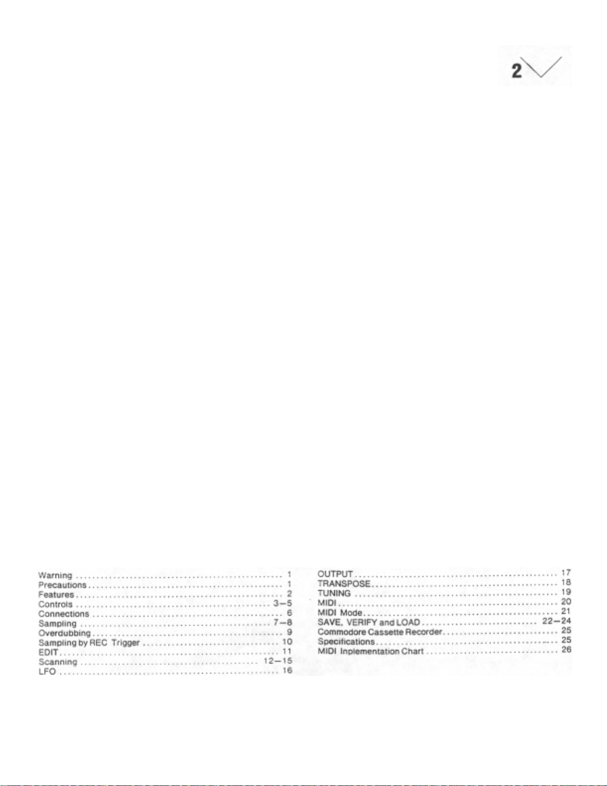
The lightning flash with the arrowhead symbol
superimposed across a graphical representation of a
person , within an equilate ral triangle , is intende d to
alert the user to the presence of uninsulated
"dangerous voltage" within the product's enclosure;
that may be of sufficient magnitude to constitute a
risk of elec t ric shock.
The exclamation point within an equilateral triangle
is intented to alert the user to the presence of
important operating and maintenance (servicing)
instructions in the literature accompanying the
appliance.
Page 3
AKAI MIDI DIGITAL
SAMPLER S612
The Akai MIDI Digital Sam pler S612 is an amazingly sophisticated electr onic
instrument which enables you to record (sample) any kind of sound, and
reproduce it at any desired pitch or pitches. The following are only a few
examples of the many sounds that the S612 can sample.
1. Sounds of acoustic musical instruments (such as pianos,
strings or percussion instruments).
2. Sounds of nature (such as sounds made by animals, wind,
wild birds and rain).
3. Human voices, radio, television, CDs, analogue records, me
chanical noises, etc.
With the S612, you are able to perform musically with ease using a wide
variety of sound sources (only a few of which are listed above). The acoustic
instruments can be sampled and reproduced as realistically as the original
sound. Existing synthesizers, up to now among the most advanced electronic
musical instruments, are unable to sample and reproduce in this way.
The S612 offers entirely new and unique ways to express your musical
creativity.
Features
Realization of super high quality sound by 12-bit sampling technology.
6-voice polyphonic performance is possible in connection with MIDI
keyboards, synthesizers, sequencers and many others.
Realization of sampling time up to eight seconds.
A short sampled sound can be continuously played with no time
restrictions and without sounding awkward. The S612 contains an
advanced scanning mode system with "looping" and "alternating" modes.
The best splicing point for "looping" can be selected instantly by the
automatic splicing system.
A splicing point can be selected at any time by switching to the manual
splice mode.
Because the starting or ending point of the sample can be selected at
any time, it is possible to play the sound after elimination of an
undesired portion of the sample. It is also possible to reproduce the
sample in reverse.
It is possible to overdub samples and accumulate various sounds
infinitely.
The S612 is equipped with an L.F.O ., which ca n add vibr ato effects with
a delay.
The S612 is also equipped w ith continuous variable low-pass filters for
adding a milder touch to samples.
2.8 inch sample disks can be used for data files. "Save" and "load"
procedures are extremely quick. You can continuously build your own
tone sample library with the specially designed Sampler Disk Drive
MD280. (optional)
Any type of sound can be tuned to a designated pitch by transposing it
by a half step. This can also be d one by tuning ±100 cent. The sound
can then be stored on a disk.
The S612 is rack mountable (EIA/2U type) for excellent oper ation in the
studio as well as at live performances. It can be handled with ease and
offers astonishing performance.
Table of Contents
Page 4
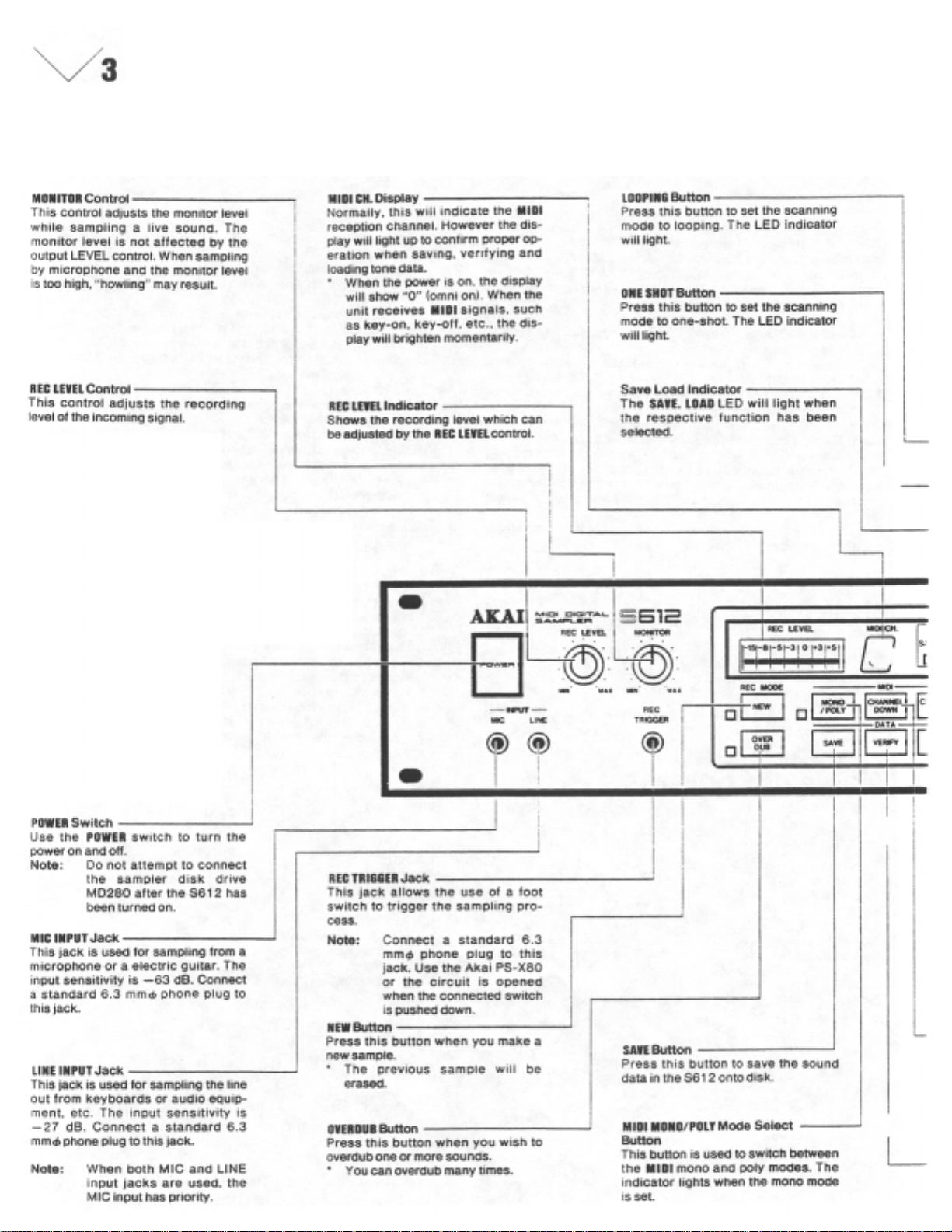
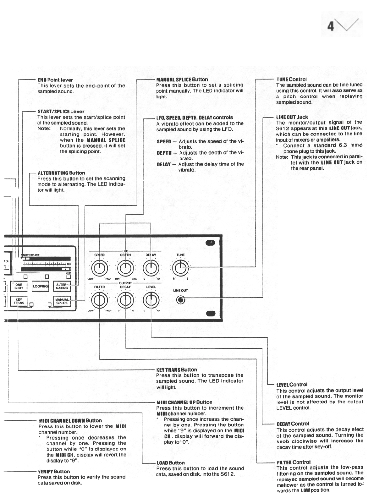
Controls
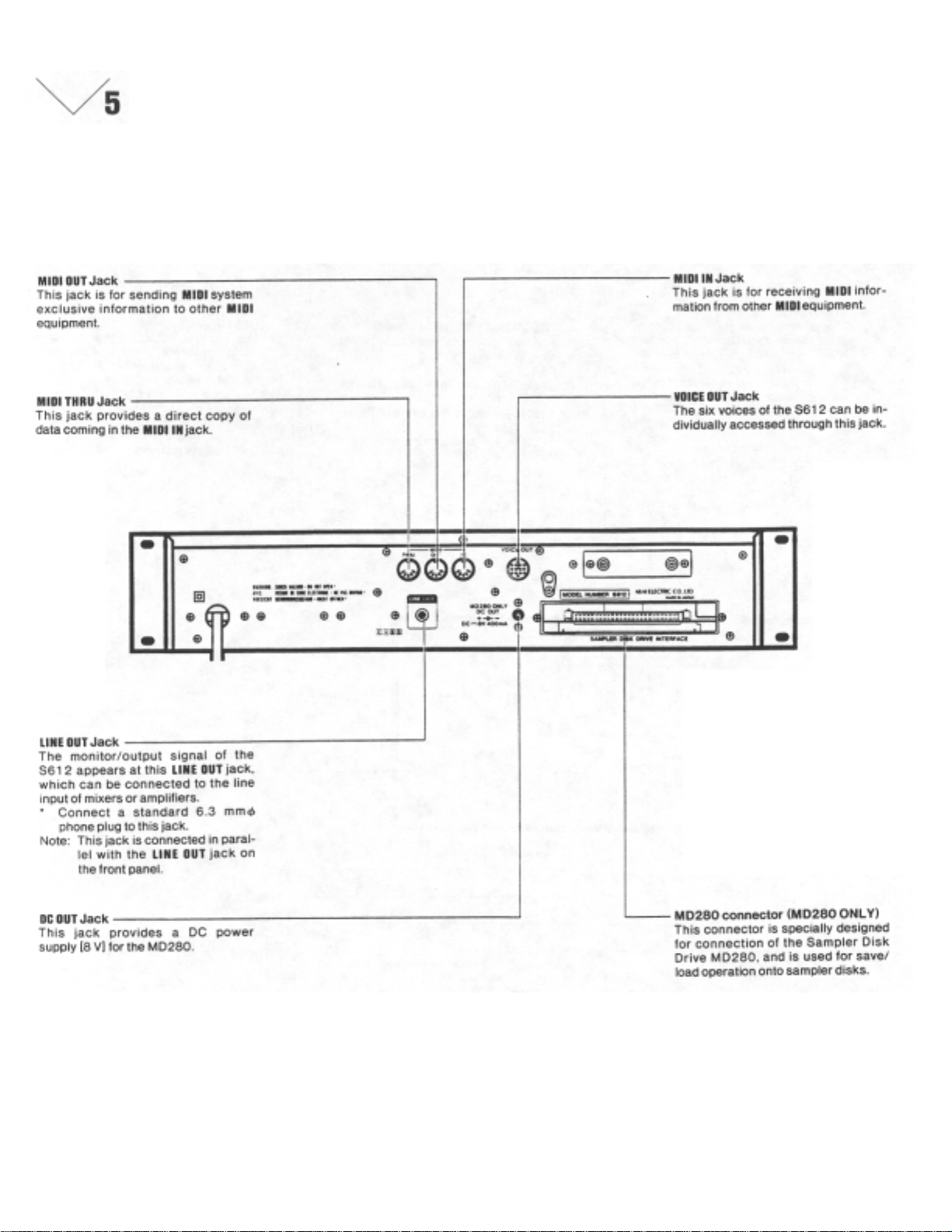
Page 5
Page 6
Page 7
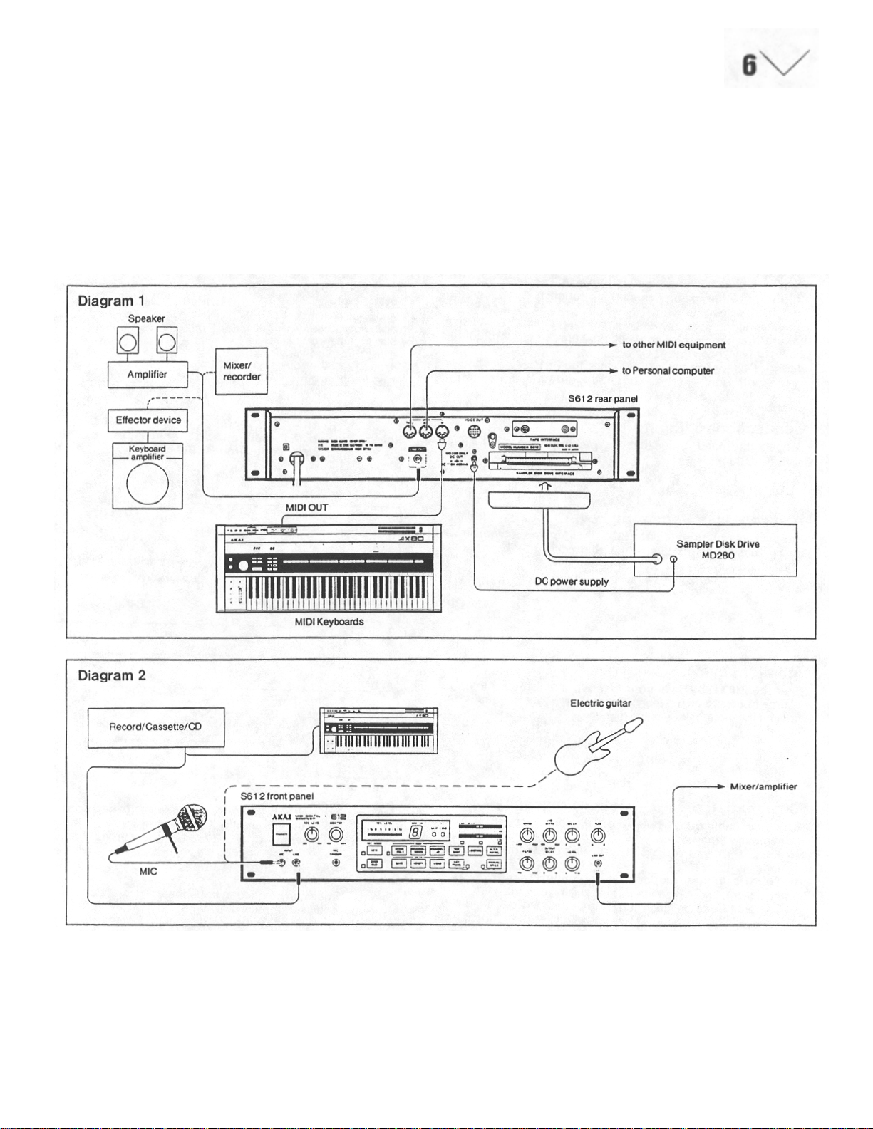
Connections
The S612 is a MIDI digital samp ler which will function only if input
information is received at MIDI-IN. Ensure that all the correct connections
have been made between the MIDI - IN and MIDI-OUT of t he S612 a nd a ny
keyboards (such as the Akai
AX80) or sequencers. Obviously, unless a sound is being input or a sample
has been loaded into the S612, it will not reproduce any sounds. The S612
will not "remember" any data after it has been switched off.
Sampler Disk Drive MD280
The Sampler Disk Drive MD280 (opt ional) is t he device which quickly and
accurately saves the sound data. The format of 2.8" disk makes the filing
space very compact.
Note: If the MD280 is to be used, it should be connect ed with the S612
before switching on the S612, Any sampled data in the S612 will
be lost if the MD280 is plugged in or unplug g e d while the S612 is
switched on.
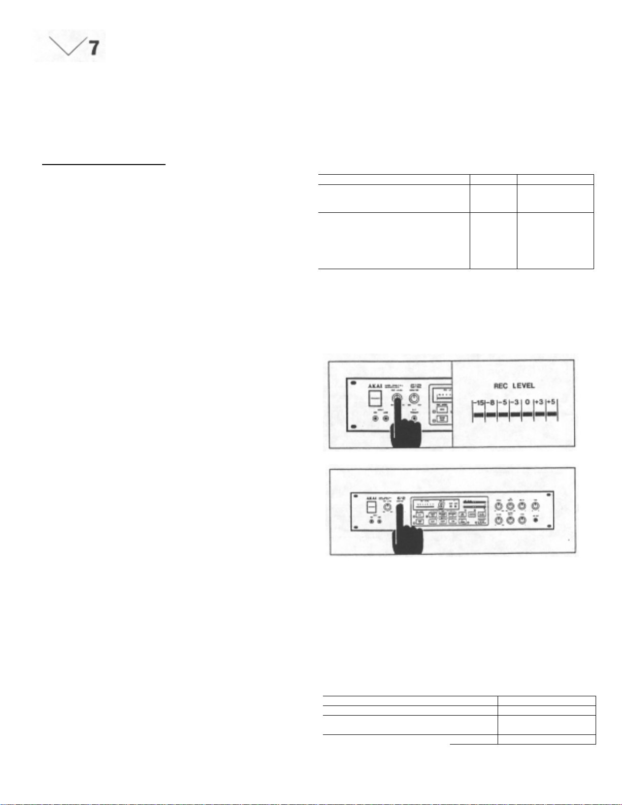
Page 8
y
Sampling
PREPARATIONS
Before Turning the Power On
Make sure the various connections with MIDI and audio equipment
have been completed before turning the power of the S612 on.
(Refer to the chapter concerning connection with external
equipment on page 6.)
When using the specially designed MD280 Sampler Disk Drive,
ensure that the correct connections between the MD280 and the
S612 have been made.
Note: Connecting the MD280 whi le the S612 is swi tched on will
result in the loss of sound data sampled in the S612.
Connections to Input
Connect the sound source that you want to sample to the MIC or
LINE INPUT jacks.
Adjustment of Recording Level
Set the recording level by the REC LEVEL control. To obtain the
best results in sampling, bring the level close to "+3" on the REC
LEVEL indicator.
Table 1
Equipment to tie connected. Input Input Sensitivity.
Equipment or devices, such as
guitars or microphones, have low
output levels.
Audio equipment, such as
televisions, cassette tape decks, CO
players, tuners or preamplifiers, or
musical instruments, such as LINE -27 dB
synthesizers or electric keyboards
have higher output lev els (lin e leve l).
Note: When both the MIC and LINE INPUT jacks are connect
ed, the MIC jack overrides LINE jack.
MIC
-63
dB
Monitor Level
Use the MONITOR level control when monitoring the sound source
to be sampled. When using a microphone, feedback may occur if
the monitor level is too high.
Designation of the Sampling Frequenc
This brief outline may help to clarify some different aspects of
sampling technique:
Are you trying to reproduce (a) high or (b) low frequency sounds?
(a)To faithfully reproduce high frequency sounds, a faster
(therefore, s horter) sampling time will be required .
The S612 can be "instructed" to accept a wider bandwidth
sample by pressing a higher note on the MIDI keyboard prior
to making the sample: see Table # 1.
(b)The reproduction of lower frequency sounds, typically much
longer in dura tion, will require a longer sampling tim e .
The S61 2 can be "instructed" to accept a long sample by
pressing a lower note on the MIDI keyboard prior to making
the sample; see Table # 1.
(c) For accurate reproduction (pitch) of a sampled sound it is
necessary to first press the same note on the MIDI keyboard
as that being sampled.
This process can be extended to allow for pitch transposition if
required.
Example: Press A2 (lowest A) on the MIDI keyboard, then
This technique can be used to transpose from 1 /2 stops thro ugh to
several octaves if required.
Note: If the MIDI keyboard or the S612 have just been
Key No. C2
MIDI Note No. 36
Sampling
frequency
Sampling Time 8 sec. 4 sec. 2 sec. 1 sec.
Note: Although only four ( 4) ke ys ar e de pi c te d, oth er ke ys ma y
play (sample) A3 (A string) on a guitar. Now when
A3 is played on the MIDI keyboard the actual
pitch of the reproduced note will be A4: The pitch
has been transposed up by one octave.
switched on and no key has been pressed before sampling, the S612 will automatically designate C4 as the
desired pitch.
4 kHz I 8 kHz ' 16 kHz 32 kHz
be selected if intermodiate frequencies are desired.
C3 C4 C5
48 60 72
Page 9
Sampling
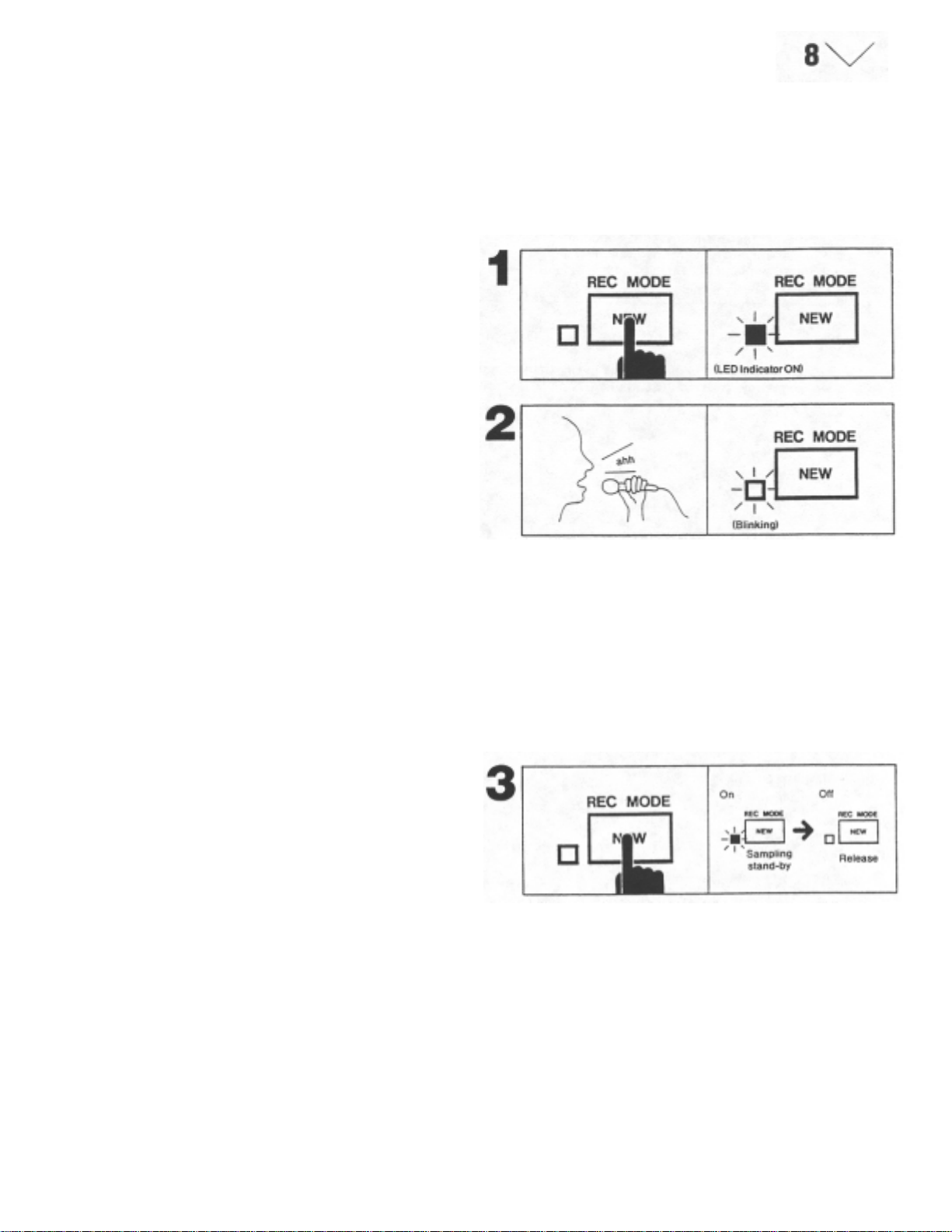
1. Once you have adjusted the recording level and designated the desired
sampling frequency, you are ready to sample. Press the NEW button.
The LED indicator will light. This indicates that the unit is standby for
sampling.
2. Using a microphone, make a sample. Say "ahh..." for example. The LED
indicator should start blinking from the moment you begin speaking into
the microphone. After blinking for the length of time of the designated
sampling frequency, the LED indicator will go out automatically. This
indicates the completion of the sampling process.
Automatic Trigger
Because the S612 contains an automatic trigger circuit, it will the sampling process may not begin because the sound level
automatically start the sampling process when the sound is not high enough to trigger the circuit. In which case, after
level reaches a certain preset level. You will notice that the increasing the recording level, reset the unit by p ressing the
unit may start off the process prematurely by picking up sur- NEW button again to get it into the standby mode, then start
rounding noise when the sampling is done through a microph- sampling.
one. On the other hand, when the recording level is too low ,
Cancelling the Sampling Standby Mode
To cancel the sampling standby mode, press the NEW button again. The LED
will go out.
3. Thus, sampling has been completed. This sampled sound
data will be maintained until either the power is turned off, the
process is repeated for another sampling or other sampled
data is loaded from the disk (tape).
If necessary, save the sound data for later use with the
specially designed Sampler Disk Drive MD280 (optional).
Refer to page 22.
4. You should now be able to enjoy six-voice polyphonic, veloci
ty touch sensitive sounds, from the S612, by playing MIDI
keyboard instruments.
Note: All six voices may not be able to be heard when music
Is played mostly on the keys around the fifth octave (the
highest octave range for the AX80). This is not a defect
in the unit.
5. After connecting the MIDI keyboards, if sampling is done with
out any keys being pressed down, the sampling frequency
will be set at 16 kHz with a sample time of 2 seconds.
Cautions when Designating the Sample
Frequency
1 . Because th e last key to be pressed down will determine the sampling
frequency, if connected with MIDI keyboards, make sure to press down
the key to designate the frequency before going through the sampling
process.
2. The range of the keys to which a sampling frequency can be designated
is between MIDI key number 36 (C2) and 72 (C5). The keys out of this
range are invalid.
Page 10

p
y
Overdubbing
By means of pressing the OVERDUB button instead of the NEW button
for the above mentioned sampling process, you are able to overdub a
newly sampled sound without erasing the previously sampled sound .
1. After adjusting the recording level and designating the sampling
frequency, press the NEW button. Sample your voice (ahh...).
2. You are about to overdub (ohh...) on (ahh...), which you have just
sampled. (It is possible to designate the sound to a different frequency.)
Press the OVERDUB button. The LED next to the button will light. This
indicates the unit is in standby for overdubbing.
Let's try to overdub (ohh...) as a second sound over the first sound
(ahh...). The setting-up process is identical to the previous chapter for
ling (Refer to page 8).
sam
3. Say (ohh...) into the microphone. From the moment you started to say
(ohh...), the LED should start blinking. This blinking indicates
overdubbing is in progress. After blinking for the length of time
equivalent to the designated frequency, the LED will go out
automaticall
4. Thus, the overdubbing process has been completed. When you play the
MIDI keyboard, you should be able to hear the combined sounds of
(ahh...) and (ohh...).
Overdubbing can be done as many times as you wish.
Note: Once the overdubbing is done, there is no way to single out
.
the individually sampled sounds. We, therefore, recommend
that you store and save the individual sounds on disk if they
are needed for later use.
OVERDUB SOUND LEVEL
As with any overdubbing process, there will be some attenuation (reduction)
of previously recorded material (approximately -6 dB) for each "take".
If it is desired that the combined sounds are to be of equal level when
replayed, then, the last sound to be sampled should be recorded at a lower
level to compensate for the attenuation of previous samples.
Page 11

gg
A
f
j
g
g
Sampling by Rec Tri
lthough the S612 contains an automatic trigger system, it is possible to
start sampling at any desired time by connecting a foot switch to the
REC TRIGGER jack, (It can be used for overdubbing as well.)
1. Connect the Akai PS-X80 foot switch to the REC TRIGGER
In this case, the automatic trigg er system will be overridden.
Use a foot switch of the type shown below, if you do not use the Akai
PS-X80 foot switch.
Normal (closed)
Press Down (open)
er
ack.
This REC TRIGGER feature becomes eapecially useful and e
situations where the sound is slow in reaching the required trigger level,
and therefore, "its" initial attack may not be sampled.
fective in
2. The settin
page 7). After adjusting the recording level and designating the sampling
frequency, press down the NEW button (or OVERDUB button). The
LED next to the button (either NEW or OVERDUB, depending on the
process you are using), should light. This indicates the unit is ready for
sampling (or overdubbing).
3. Samplin
connected to the REC TRIGGER jack.
-up process is identical to the chapter for sampling (Refer to
(or overdubbing) is initiated by pressing the foot switch
Page 12

g
EDIT
Edit
The S61 2 contains various editing functions so that sampled
sounds can be applied more effectively for your musical expressions. These functions include the following:
• Scanning
• LFO
Output
• Transpose
• Tune
1. SCANNING
This is the function that is controlled by the "START POINT" and
"END POINT" levers, in conjunction with the "ONE SHOT",
"LOOPING" and "ALTERNATING" mode buttons, that enables
you to decide h ow the sample will be replayed.
2. LFO
It is possible to add a vibrato effect to sampled sounds.
3. OUTPUT
It is possible to control the degree of mellowness of the sampled
sound (FILTER). It is also possible to adjust the length of time
the note sounds after the key-off (DECAY).
4. TRANSPOSE
It is possible to transpose the samples.
5. Tune
It is possible to tune the samples up or down within the range of
±100 cents.
When savin
along with the sampled data, therefore, when the sampled data is
retrieved (loaded) from disk, it is ready for playing in its' original,
edited form, until/u nless the ed iting co ntrols) is /are read justed. For
example, if a sound, which has been edited, using the LFO, to
contain a very deep vibrato, is saved to disk and then, at some
later date is loaded back into the sampler, even though, in the
meantime, the LFO controls may have been reset to minimum,
that sound will still contain a deep vibrato. However, if any of the
LFO controls are adjusted after the sample has been loaded, they
will again affect the character of the sound. This superior feature
enhances the "useability" of the S612 Digital Sampler.
Note: The output LEVEL control is not a programmable parame
ter.
to disk, the editing parameters will also be stored
Page 13

Scanning
S
The S612 stores sampled sounds in memory IC's in digital data form and
reconstructs the pitch by altering the speed at which the memory data is
read. It works on the same principle as a tape recorder. The pitch
changes according to the tape speed. However, because sounds are
recorded differently in memory IC's than on tapes, it is possible for us,
using the in-
Normal Setting
In order for the scanning functions to be easily understood, let's suppose a
situation where we have sampled a phrase "Good Morning". Picture also the
situation where the phrase "Good Morning" is stored in digital data form in
the memory ICs of the S612, as seen in the diag ram. In the nor mal setting,
scanning is done from truncating front to the truncating rear all the way
through. This means that with a key-on, the sampled phrase "Good Morning"
will be played, and there will be no more sound. In this case, even if the key
is held down, there will be no sound after the phrase "Good Morning" is
played once.
tarting Point and Ending Point
Starting Point
By adjusting the START/SPLICE lever, it is possible to set a starting point
(the point where the S612 starts replaying from the m emory ICs) at any
desired point.
For example, if you choose "Morning" to be the starting point, after sliding
the lever to the appropriate position, the "Morning" portion of the phrase will
be replayed when a key is pressed, as seen in the diagram.
Note: Re-trigger a key each time the lever is moved to deter
mine (hear) the new starting point.
The START/SPLI C E lever has two (2) functions.
Normally (if the MANU. SPLICE button has not been pressed), the
START/SPLICE lever has the function of setting a starting point. On the
other hand, when the S61 2 is in the manual splic ing mode (the MANU.
SPLICE button having been pressed), the lever has the function of setting
splicing point. (See Page 15)
Ending point
By adjusting the END POINT control, it is possible to set an ending point
(the point where the S612 stops r eplaying from the memory ICs) at any
desired point.
For example, as seen in the diagram, by adjusting the control to the
appropriate point, only "Good" will be p layed when a key is pressed.
ternal computer of the S612, to control the ways in which the data in the
memory IC's is read. In other words, it is possible to designate the point
at which the S612 starts reading or stops reading the data in the
memory IC's; to make a loop, or to reproduce a reverse version. We call
these functions "Scanning".
Page 14

p
Playback of Reverse Version
If you set the two levers so that the END point lever is positioned
before the START point lever, the playback will be reversed. For
example, as seen in the diagram, when the set up is done with the
start point at the truncating rear and with the end point at the
truncating front, the reverse version "gninroM dooG" will be played
when a key is pressed. It follows, therefore, that it is possible to
replay any desired portion of the sample in reverse.
Note: Although the START and END point levers may be
reversed, it is not possible to SAMPLE in reverse. A
sound can only be recorded as it occurs naturally (in its'
original form) even through, once sampled, it can be
roduced in reverse.
re
Scanning Mode
The S612 employs the latest computer technology so that it is
not only able to play sampled sounds, but can also be used very
extensively for musical applic ation.
The following are three special scanning modes:
' One-Shot
Looping
Alternating
One-Shot mode
In the "One-Shot" mode, the S612 functions as an ordinary sampling device. For example, when it is set as shown in the diagram
(the same as the normal setting), the sampled sound "Good
Morning" will be played when a key is pressed. There will be no
sound thereafter, even if the key is held down.
With the one-shot mode, scanning is done in the following order.
Starting point - Ending point
Page 15

A
Looping Mode
In the LOOPING mode, the setting up of a loop automatically (automatic splicing
system) or manually (manual splice mode) within the S61 2's memory IC's makes it
possible for the sampled sound to be played continuously. With this mode, playing the
continuous sounds of strings, brasses, chorus, etc., becomes possible. (The sound
starts when a key is pressed and will play continually until the key is released.) This
makes the application of the S612 very extensive by opening up more paths for your
musical expression.
Automatic Splicing System
The S612's looping function makes it feasible, by fully applying today's computer
technology, to search out and automatically "Splice" any point ("Splici ng Point") of the
sample instantaneously. This has been said to be very difficult and time consuming
without the aid of the computer.
The term "Splicing" is used when joining two audio tapes together with a special
adhesive tape to make one continuous tape when editing is necessary. Similarly, we
call the restarting point of a scanning loop a "Splicing Point".
The moment the LOOPING button is pressed, the automatic splicing system of the S612
finds the most appropriate splicing point of the sampled sound. For example, as seen in
the diagram, when the LOOPING button is pressed, with the START/END point levers in
the normal position, the key-on (when a key is pressed) will start the sampled phrase
"Good Morning". After "Good Morning" is played once, "ing" will repeat continuously until
the key-off (the key is released). This means that the S61 2's computer selected "O" as
the beat splicing point.
In the LOOPING mode, the scanning is done in the following order:
Starting point - Ending point -- Splicing point
lternating Mode
The ALTERNATING mode is based on the same idea as the LOOPING mode where a
loop is built by scanning. But it is different from the LOOPING mode in the way the loop
is built. For example, as seen in the diagram, when the ALTERNATING button is
pressed, with the START/END point levers in the normal position, the key-on will start
the sampled phrase "Good Morning". After "Good Morning" is played once, "gni" then
"ing" will be replayed continually until the key-off. The scanning simply reverses direction
between the end point and the splicing point.
In the LOOPING mode the scanning "jumps" back to the splicing point: scans only from
the splicing point to the end point; does not scan from the end point to the splicing point.
This difference in scanning should be comprehended more easily in the next chapter for
"Manual Splice".
In the ALTERNATING mode, scanning is done in the following order:
(Reverse)
Starting point -
Note: The ALTERNATING mode is very useful, especially when it
comes to building the continuous sounds of strings. But there
are some instances where the sound produced by the looping
mode is more acceptable. Compare the LOOPING mode and the
ALTERNATING mode when editing and select the continuous
tone which sounds better.
Ending point ------------------Splicing point
Note: The automatic splicing point is referenced to the position of
the END POINT lever. Therefore, if the sampled_sound does not
utilize all of the available memory the computer will be attempt
ing to replay (loop) an "empty" memory; = no sound! This situ
ation can be remedied by repositioning the END POINT lever,
making a longer sample or, shortening the sample time.
Some sound will not loop well. Sounds which are not produced
by musical instruments (human voices, effects and so on) or,
with erratic or staccato-like sounds which contain much varia
tion, some noise (splicing noise) may be heard. This is not a
defect. Experimentation may be necessary with some sounds.
The automatic splicing system will be overridden if the
MANUAL SPLICE mode is selected.
Page 16

Manual Splice Mode
The S612 normally sets up a splicing point by using the
automatic splicing system. However, by pressing the MANUAL
SPLICE button, the automatic splicing system will be ov erridden,
which makes it possible for you to set a splicing point manually.
In this situation, the START/SPLICE lever's function is to set a
splicing point and by adjusting this lever, a different splicing
point may be set. For example, in the LOOPING mode, when
the MANUAL SPLICE button is pressed and the splicing point is
set at "Morning" by the lever, a key-on starts the phrase "Good
Morning". After the phrase is played once, "Morning" will be
repeated until the key-off.
In the ALTERNATING mode however, a key-on starts the
phrase "Good Morning". After the phrase is played once,
"gninroMMorning-gninroM" will be repeated until the key-off.
Note: The MANUAL SPLICE button will not function in the
one shot mode.
Page 17

LFO
Because the S612 contains an LFO (Low Frequency Oscilla t or ) circuit, it is
possible to add vibrato effects to sampled sounds. The waveform of the LFO
is ~.
SPEED Control
This control sets the modulation rate of the LFO.
DEPTH Control
This control sets the depth of the modulation.
DELAY Control
This control sets the delay time of the vibrato.
Note: The three controls for the LFO (SPEED, DEPTH and DELAY)
are programmable parameters. When sounds are to be saved on
disks, these data will be saved along with the sampling data.
Note: It is possible to add a vibrato effect not only with the LFO. but
also by operating the modulation wheel on external MIDI
keyboards. (Refer to MIDI on page 20.)
Page 18

OUTPUT
The S612 has three OUTPUT controls, FILTER. DECAY and LEVEL.
FILTER Control
By processing the sampled sound through a
low-pass filter, it is possible to give it a milder or
a mellow tone.
DECAY Control
By adjusting the DECAY control, a decay
(reverb-like) effect can be added, so that when
the key is released (key-off) the sampled sound
fades gradually.
The higher the value (number) that the control is
set at, the longer the decay effect.
NOTE: The S612 can r eceives deca y effect by
"Sustain Pedal On" data from external
MIDI keyboards.
LEVEL Control
This control is for adjusting the output level of sampled sounds.
Note: The adjustment of this control does not affect the moni
tor level.
Of the three OUTPUT controls, the FILTER and DECAY are
programmable parameters. When the sound data is
saved on disks, they will be saved along with the
sampled data, However, because the LEVEL data is not
programmable, it cannot be saved on disks.
Page 19

y
TRANSPOSE
The S612 is able to transpose sampled sounds by a half-step interval
through to several octaves, so that they can be played at any desired pitch.
The transposition is enabled by the MIDI keyboard. For example, let's
transpose the sampled sound up by one octave.
Transposition
For example, let's transpose the sampled sound up by one octave.
Note: All transpositions are made relative to middle C.
Listen to the sampled sound of C4. (Middle C)
Press the KEY TRANS button. The LED indicator will start
To move the pitch of the sound by one octave, press down the ke
MIDI note No. 72 (C5 for AX80). The S612 d oes not produce any sound
in this case.
Upon completion of the key-on process, the LED indicator will stop
blinking and stays lit, indicating the completion of the transposition.
At this time when you press down the key of MIDI note No. 60, you will
get the C5 sound.
The transposition for one octave up has now been completed.
If you wish to transpose to the fifth interval up, press down the key of
MIDI note No. 67 (G4 for AX80).
When you wish to go back to the original sampled pitch, depress the
KEY TRANS button while the KEY TRANS LED blinking, the transpose
mode will be cancelled.
of
Note: The S612 must be connected to MIDI keyboards in
order to use the transposing function.
The transposing function is programmable. When you
wish to save a sound onto disk, the transposition will be
saved along with the other data.
Page 20

TUNING
With the S61 2's "Tuning" function, it is possible to freely tune a sampled sound
within a range of ±100 cents (a half step), and to save the tuning parameters along
with the sampled data. In other words, the data for the TUNE control are
programmable.
Tuning when Sampling
When sampling, the tuning is based on the center position of the TUNE control.
1. W hen the sampled sound is played and the TUNE control points to the center, as
shown in the diagram, the sound will be reproduced with the same pitch.
2. W hen the sampled sound is played, and the TUNE control is turned fully right (left)
as shown in the diagram, the pitch will be a half step higher (lower).
Tuning when Saving
Because the TUNE control is programabte, the data to be saved on disks (tapes) will
correspond to how much to the right (or left) the control is turned.
Example: If the note A is sampled and then retuned, using the TUNE control, by +100
cent and saved to disk, when the A key is pressed the note A# will be
played. However, provided that the TUNE control is not reset, once the
save is verified the tuning will again move by +100 cents. This means that
now, when the A key is pressed, the note B will be played. It is possible to
achieve the previously desired note of A# by resetting the TUNE control to
the center position.
Tuning when Loading
When sound is loaded from di sk (tape) the tuning will be either higher or lower than the
tuning which had been saved, depending on the present position of the control.
1. When the loaded sound is played and the TUNE control is positioned in the center,
the pitch will be the same as the tuning which has been saved.
2. W hen the loaded sound is played and the TUNE control is set at +50 cents from the
center position, the sound is played +50 cents higher than the saved tuning.
When the sound data is loaded from disk (tapes), the present position of the TUNE
control will add to, or subtract from, the pitch of the saved data. For example, suppose
that the sample was saved 50 cents higher than the originally sampled sound and that
the loaded sound is played with the TUNE control set at +50 cents. In this case, the pitch
will be (+50) cents + (+50) cents = + 100 cents, which is a half step higher than the
original sound.
Tuning When Playing after Loading
As stated earlier, after the sound data is loaded, the pitch of the replayed sound will
depend on the present setting of the TUNE control (regardless of where the TUNE
control was set during loading).
For example, suppose that a sample is retuned to +50 cents and then saved to disk
(tape). When that sample is loaded from disk (tape), i f the TUNE control is still set at +50
cents, then the replayed sound will now be at (+50) cents + (+50) cents = + 100 cents; a
half step higher than the original sample. However, if the TUNE control is reset to the
center position, the replayed sound will now be at only +50 cents higher than the original
sample: the pitch at which the sample was saved. It followes. therefore, that if the TUNE
control were to be set at -50 cents, the replayed sound
0 cent; zero change; which means that the sound will now be the same pitch as the
original sample.
will be (+50) cents + (-50) cents =
Page 21

MIDI
y
MIDI (Musical Instrument Digital Interface)
This is the Internationally recognized standard for electronic musical
instruments. It is possible for these instruments to exchange any kind of
information needed for musical performanc e, b y utiliz ing t heir MIDI
connections. The S612 is able to receive the following MID I information
through midi cables:
When the S612 receives the MIDI information, its MIDI CH display, which
indicates the MIDI channel numbers, will brighten m omentarily to let you
know that information has been received. (If the MIDI reception channel
does not match, the display shows no change.)
How to set the MIDI Reception Channel
1. When the power is turned on, the S612 initiates to the PO LY mode of
omni on. In this case, it will receive any channel and play according to
the information. The digit "0" on the MIDI CH displays shows omni on.
Note No., Ke
Sustain pedal
Pitch bend
Modulation wheel (vibrato)
Mode change for Mono/Poly
System exclusive
-On, Key-Off and Key Velocity
2. When you want to reselect the MIDI reception channel (1-9), press either
the CHANNEL DOWN or CHANNEL UP button until you reach the
desired number. In this case, the S612 rec eives information only on the
designated MIDI channel.
Page 22

(
MIDI Mode
There are four MIDI modes possible, from combinations of the
MONO/POLY mode and the OMNI ON/OFF mode.
OMNI ON, POLY mode
With this mode, the S612 will receive the MIDI information from any
channel, and 6-voice polyphonic sound can be played simultaneously on a
channel.
The OMNI ON. POLY mode is selected automatically when the S612 is
turned on.
The MIDI CH display shows "0" during this mode.)
OMNI ON, MONO mode
With this mode, the S612 will receive the MIDI information from any
channel. However, only one sound can be played at a time on any channel.
Press down the MONO/POLY button once. (The LED ind icator w ill light.)
OMNI OFF, POLY mode
With this mode, the S612 will receive the MI DI information only from the
channel which has been designated as the reception channel, and 6-voice
polyphonic sound can be played simultaneously on a channel.
When the MIDI CH display numbers 1-9 are select ed, the S612 is in the
OMNI OFF mode.
OMNI OFF, MONO mode
With this mode, the S612 will receive the MIDI infor mation only from the
channel which has been designated as the reception channel. When numbers
1-9 are selected, the One-voice sound corresponding to the designated
channel can be played. Also the designated channel voice can go thru the
VOICE OUT jack.
Page 23

T
g
g
g
SAVE, VERIFY and LOAD
The sampled sound data can be saved, verified or loaded by the
specially designed sampler disk drive MD280 (optional) or a
Commodore cassette recorder. The time it takes to save, verify
or load with the MD280 is approximately 8 seconds. The
Commodore cassette recorder takes approximately 120
seconds.
Saving
1. Edit the sampled sound of the S612, as required, before
saving.
Place the disk into the MD280 sampler disk drive.
(Make sure the tab has not been broken.)
Press the SAVE button on the S612. The letter d will appear
on the MIDI channel display and start blinking.
he sound dat a is a combination of sampled and edited
*
data.
The operation of the sampler disk drive MD280 or the
Commodore cassette recorder, will be controled by the
S612.
Note: Make sure the power switch of the S612 is turned
before plugging or unplugging the connection cord of
the MD280.
off
2. Press the SAVE button a
d display remain lit and the SAVE LED lit, indicating that the
save function is in progress.
Note: The d display will only blink for several seconds. The
SAVE button must be pressed a second time while the
display is blinking to activate the save function,
otherwise, the SAVE mode will be cancelled.
3. The BUSH LED on the MD280 will li
function is in progress.
ain, while the display is blinking. The
ht indicating that a save
It takes approximately 8 seconds to accomplish the save. Once
saving is completed, the SAVE LED of the S612 and the BUSY
LED of the MD280 will go out. After save function, verify that
the data has been properly saved.
Note: If you encounter any difficulty when tryin
check the following, and try saving again.
* The anti-record tab has been broken from the
disk.
* You are trying to save without inserting a disk in
the MD280.
* The power cord of the MD280 is not connected.
* There is no sample in the S612.
to save,
Page 24

Verifying
1 . After the save process has been
completed, Press the VERIFY button.
2. The letter d will appear on the MIDI CH display. At the same
time, the BUSY LED of the MD280 will light, indicating that it
is in the verifying process.
3. The verifying process takes approximately 8 seconds. If the
data has been correctly saved, the letter G on the MIDI CH
display will blink for several second.
The display will return to its previous condition after a few
seconds.
4. If the MIDI CH display will indicate the letter E and blink for
several second the data has not been correctly saved. (After
a few seconds, the MIDI CH display will return to its previous
condition.)
Try to save function once more time.
Note: If several unsuccessful attempts have been made to
save and verify, the head may need cleaning or the
felt may need changing on the MD280 or the
sampler disk may need change. Consult your
MD280 Operator's Manual for details.
Page 25

g
g
Loading
1. Set the sampler disk w ith sound d ata into the MD280.
* Press the LOAD button of the S612.
2. The LOAD LED will li
letter d on the MIDI CH display will appear to let you know t he S612 is
being loaded from the disk.
Also, the BUSY LED of the MD280 will light, indicating that loading is in
progress.
3. Loadin
4. If the data has not been loaded correctly, E will appear and blink for few
will take approximately 8 seconds. If the data has been loaded
correctly, the MIDI CH display will return to its previous condition.
seconds before the MIDI CH display returns to normal. If this happens,
check the following:
* Has the disk been inserted correctly?
* Is the disk blank?
* Has the disk been close to a strong magnetic field?
* Are the power and interface cables connected properly?
ht and loading will begin. At the same time, the
Page 26

[ MIDI DIGITAL SAMPLER
p
t
N
N
N
,
Model 5612 MIDI Im
lementation Char
Transmitted Recognized Remarks
Function
Basic Default 1
Channel Changed 1 - 9 * note
Default 1
Mode Messages MONO POLY
OMNI ON/OFF
Altered ************** 1 2 3 4
ote 0 - 127
umber : True voice ************** 36 - 96
Velocity Note ON O 9nH v=1-127
Note OFF x 9nH v=0,8nH
After Key's x
Touch Ch's x
Pitch Bend er O
Control 1 O Modulation
Change 64 O Damper
Prog X
Change : True # **************
System Exclusive O O
System : Song Pos X
: Song Sel X
Common : Tune X
System :Clock X
Real Time :Commands X
Aux :Local ON/OFF X
:A11 Notes OFF O
Mes- :Active Sense X
Sages :Reset X
otes * OMNI ON ---------------- Basic Chann = 1
Mode 1 : OMNI ON, POLY Mode 2 : OMNI ON, MONO O: Yes
Mode 3 : OMNI OFF
POLY Mode 4 : OMNI OFF, MONO X: no
Page 27

 Loading...