

Page 1

MOBILE VIDEO SYSTEM
MODEL: ADV-85DR
Note:
Digital Audio Out-Coaxial
Multi-subtitle Languages Function
Multi-audio Languages Function
Multi-angle Function
Parental Control
Page 2

CONTENTS
Disassembly Instructions.................................................................................................................................... 3
Disassembly Diagram......................................................................................................................................... 4
Block Diagram .................................................................................................................................................... 5
Printed Circuit Board........................................................................................................................................... 6
Wiring Diagram ................................................................................................................................................... 12
Exploded View .................................................................................................................................................... 13
Exploded View Parts List.................................................................................................................................... 14
Schematic Diagram ............................................................................................................................................ 15
Electrical Parts List ............................................................................................................................................. 19
Specifications...................................................................................................................................................... 26
Page
2
Page 3

DISASSEMBLY INSTRUCTIONS
1. Remove two screws (A) from each side of the top cabinet and remove three screws (B) located on the rear of
the top cabinet then remove the Top Cabinet.
2. Remove four screws (C) located on the under the bottom cabinet then remove four Rubber Foot DVD171.
4. Remove two screws (D) located on the under the bottom cabinet and remove two screws (E) from each side
of the top panel then remove the Top Panel.
5. Remove two screws (F) from the deck front bracket and remove two screws (G) from the deck rear bracket
then remove the Main Board and the Bottom Cabinet.
6. Remove two screws (H) from the deck front bracket then remove the Deck Front Bracket.
7. Remove two screws (I) from the deck rear bracket then remove the Deck and the Deck Rear Bracket.
3
Page 4

DISASSEMBLY DIAGRAM
4
Page 5
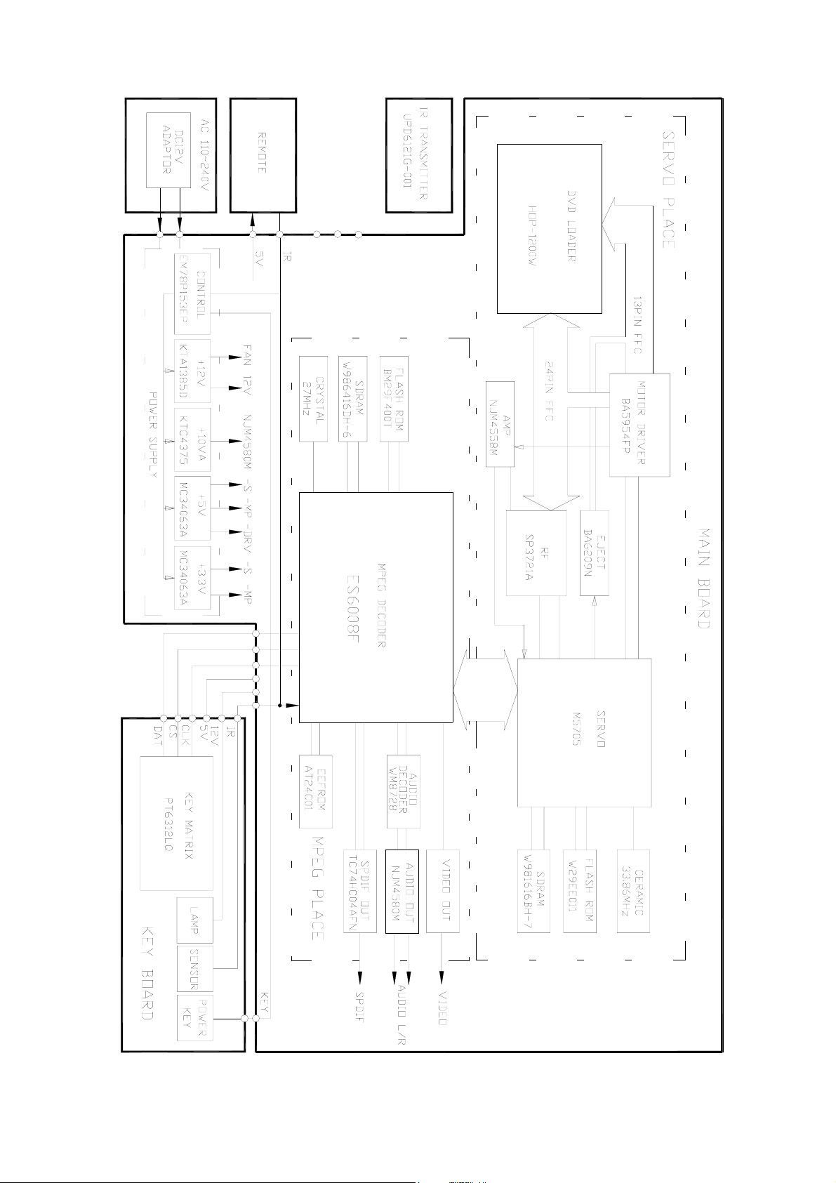
BLOCK DIAGRAM
5
Page 6

MAIN BOARD
PRINTED CIRCUIT BOARDS
TOP VIEW
6
Page 7
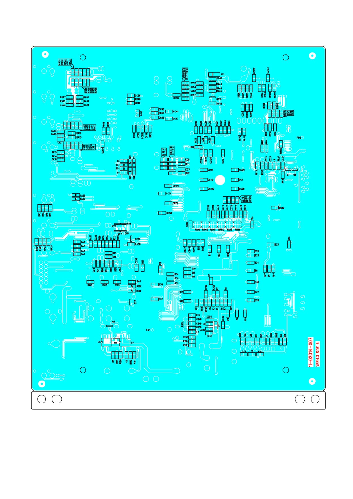
MAIN BOARD
BOTTOM VIEW
7
Page 8

KEY BOARD
TOP VIEW
8
Page 9

KEY BOARD
BOTTOM VIEW
9
Page 10
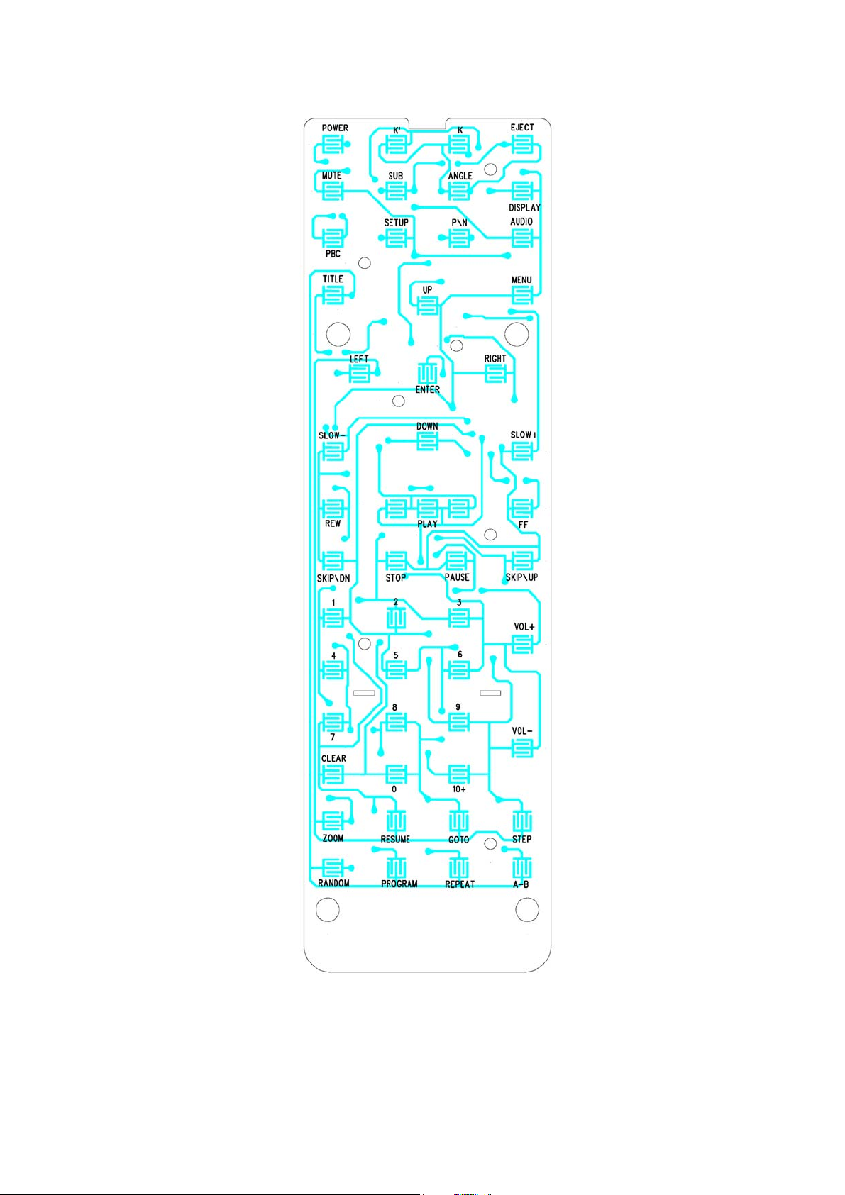
REMOTE BOARD
TOP VIEW
10
Page 11

REMOTE BOARD
BOTTOM VIEW
11
Page 12
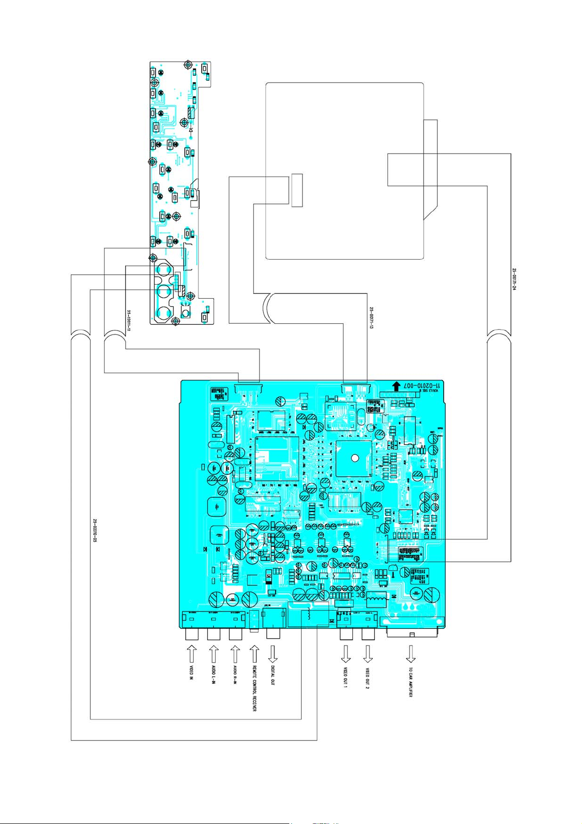
WIRING DIAGRAM
12
Page 13

EXPLODED VIEW
13
Page 14

EXPLODED VIEW PARTS LIST
Ref. No. Description RS Part No. Mfr’s Part No.
Ring (S. OPC1202)
1
Panel Top W/O TV (S. OPC1202)
2
Top Cover (S. OPC1202)
3
Bottom Cabinet W/O TV (S. OPC1202)
4
Main PCB Paper
5
Main Board
6
DVD MECH. Slot Type (Hop-1200W)
7
Deck Front Bracket
8
Deck Rear Bracket
9
Key Board
10
Shade
11
CD Windows Sheet
12
Panel Top Decoration (EA-Silver)
13
Panel Top Decoration (EA-Silver)
14
Function Key (E-Silver)
15
MENU/Power Key (L-Up) (S. OPC0000)
16
EJ/SEL Knob (L-Up) (E-Silver)
17
Stop/Next Knob (L-Up) (E-Silver)
18
51-H2020-80A
51-K2020-84Y
61-H2002-80
61-K2001-81B
43-H2001-00
11-02014-007
94-02682-00
39-B2001-01
39-B2002-01
11-02014-337
81-69005-02
43-A3101-00
52-K2022-90E
52-K2023-90E
52-K2027-90E
52-K2026-01
52-K2028-91E
52-K2029-91E
Play/Pause/PREV Knob (L-Up) (E-Silver)
19
SEL/Source Knob (L-Up) (E-Silver)
20
INDEX Light
21
1AVIN2/DVD Light
22
IR Lens
23
Lighting Sleeve
24
Rubber Foot (Clear)
25
Screw Ø2 X 5 BH/ST Black
26
Screw Ø2.6 X 4 KH/MS
27
Screw Ø2.6 X4 BH/MS
28
Screw Ø2.6 X 5 BH/TAPTITE
29
Bracket Screw M2.0
30
52-K2030-91E
52-K2024-90E
52-K2031-00
52-K2032-00
52-K2025-50R
52-K2021-00
81-D1701-01
40-12005-06
40-02604-02
40-02604-01
40-02605-03
40-A1516-00
14
Page 15

SCHEMATIC DIAGRAM (SERVO)
15
Page 16

SCHEMATIC DIAGRAM (MPEG)
16
Page 17

SCHEMATIC DIAGRAM (POWER)
17
Page 18

SCHEMATIC DIAGRAM (I/O)
18
Page 19

SCHEMATIC DIAGRAM (AV/POWER)
19
Page 20

SCHEMATIC DIAGRAM (KEY BOARD)
20
Page 21

SCHEMATIC DIAGRAM (REMOTE BOARD)
21
Page 22

ELECTRICAL PARTS LIST
Ref. No. Parts No. Description Q’ty
PC BOARD ASSY, MAIN BOARD
Q2,7,24~6,QV7,8
Q3,5,QV5,6
Q13,22,QA7~11
QQ1,2,QV1
Q4
Q1,8,QQ4,QV2,3
Q6,11,QP1
D2
D4,6,7,10~2,DD2,3,6,8
D1,3,5,DP8,9
ZZ1
Z4,ZP1
Z1~3
UU7
UV1
U2
UU2
UA1
01-00106-00
01-00106-10
01-00231-00
01-01298-00
01-01385-00
01-03265-00
01-04375-00
02-04001-01
02-04148-02
02-05819-02
02-50043-00R
02-50051-03
02-50100-02
03-01616-00
03-02235-00
03-02401-00
03-03721-00
03-04052-03
KRA106S (SOT-23)
KRC106S (SOT-23)
KRC231S (SOT-23)
KTA1298 (SOT-23)
KTA1385D-Y (DPAK)
KTC3265-Y (SOT-23)
TR. KTC4375-Y (SOT-89)
CHIP IN4001 (SOD-106)
DIODE CHIP RLS4148 1206 ROHM
CHIP IN5819 (SOD-106)
CHIP ZENER DIODE 4.3V (LL-34)
CHIP ZENER DIODE 5.1V ±5% (LL-34)
CHIP ZENER DIODE 10V ±5% (LL-34)
W981616BH-7 (TSOP II-50PIN)
IC CHIP NJM2235M JRC
EEPROM (FLAT RACK) 24C01
SP3721A (PQFP-64PIN)
IC CHIP BU4052BCF ROHM
7
4
7
3
1
5
3
1
10
5
1
2
3
1
1
1
1
1
UA2,3,UU4
U23
UU1
UU9
U1
UU12
U3
U4
U9
U30
U28
U5,7
UU5
U6
Y1
Y3
YY1
CC24/6,73~8
03-04558-26
03-04580-00
03-05705-00
03-05954-00
03-06008-00
03-06209-00
03-06416-00
03-07404-01
03-07805-01
03-08728-00
03-29400-15
03-34063-01
03-39010-00
03-78153-00
04-00270-00
04-00400-02
04-03386-00
05-63100-00
I.C. NJM-4558M
NJM4580M (SOP-8PIN)
M5705 (PQFP-176PIN)
BA5954FP (HSOP-28PIN)
ES6008 (PQFP-208PIN)
BA6209N (SIP-10PIN) ROHM
W986416DH-6 (TSOP II-54PIN)
TC74HCU04AFN (SOL-14PIN)
REGULATOR 7805 (NJM78L05UA-TEI)
WM8728 (SSOP-20PIN)
AM29LV400BT-90 DVD201H
MC34063A (SOP-8PIN)
IC W39F010P-70B (PLCC-32PIN)
IC EM78P153EP-171A DIP14
CRYSTAL 27M (HC-49/US)
CERAMIC RESONATOP 4MHZ
CERAMIC ZTA33.86MX
CHIP CAP 10PF ±5% NPO 0603 SMT
3
1
1
1
1
1
1
1
1
1
1
2
1
1
1
1
1
8
CC46,82/5,CV2,8,12
C185,190,CA19,27,30/1,CC11,21/2,47
05-63101-00
05-63102-01
CHIP CAP 100PF ±5% NPO 0603 SMT
CHIP CAP 1000PF ±10% X7R 0603 SMT
22
6
10
Page 23

ELECTRICAL PARTS LIST - CONTINUED
Ref. No. Parts No. Description Q’ty
B6~9,11/3/5~30/4~8,41/5/6,57/9,C192
2,128,191,230/2,246/7,256,CC3,6,7,9
,10/2/9
C184/8,CA17,20/5/8
C249
C216,223
C20/1,248
C3,9,CC8,59
C196/7,CC16/7,SC1~4
CC86
C8,23,CC2,15,43
C7,CC14,64/7
CC4
CC35,41/2/4/5
CC13
C6,16,180/1,213/5/9,257,B14,CV1,5,9,
CA1~6,8,11~6,22~4,CP3
C13/5,226/7,CC83,CA7,9,CV4,6,11,CA
10,CC18
05-63104-02
05-63151-00
05-63200-00
05-63222-01
05-63330-00
05-63470-00
05-63471-00
05-63472-01
05-63473-01
05-63474-02
05-63561-00
05-63681-00
05-63682-01
06-16106-02
06-16107-04
CHIP CAP 0.1µF ±20% X7R 0603 SMT
CHIP CAP 150PF ±5% NPO 0603 SMT
CHIP CAP 20PF ±5% NPO 0603 SMT
CHIP CAP 2200PF ±10% X7R 0603 SMT
CHIP CAP 33PF ±5% NPO 0603 SMT
CHIP CAP 47PF ±5% NPO 0603 SMT
CHIP CAP 470PF ±5% NPO 0603 SMT
CHIP 4700P ±10% X7R 0603 SMT
CHIP CAP 0.047µF ±10% X7R 0603 SMT
CHIP CAP 0.47µF ±20% X7R 0603 SMT
CHIP CAP 560PF ±5% NPO 0603 SMT
CHIP CAP 680PF ±5% NPO 0603 SMT
CHIP CAP 6800PF ±10% X7R 0603 SMT
E. CAP 10µF 16V (Ø3.5X5MM)
E. CAP 100µF 16V (Ø6X5MM)
104
6
1
2
3
4
8
1
5
4
1
5
1
29
12
C4,5,14
C1,10~2/7/8,CC1,5,29,55/8,116/8,122/
3,B1,10/2,31~3/9,40/2/7,56,61
CC33,50,91
RR30/3~5
RR21/3,RV3,R8,16,RA10/4,25,31
R19,RR29,37,RV5,12
R11/2/6,RR66/8,RV2
RRN6~8,13~6
R29,156,RA7,8,37
R149,159,185/7/8,RR4,15,24/6/8,40/2,
51,73,102,126/7/9,RA38~40
RRN4,5,9~12
R43,304,RR2,3,27,50
R20/4
RV1,3,4
RR1,6,38/9,RA1,2,20/1
R181
06-16108-00
06-63227-01
06-63476-00
07-05220-54
07-63000-00
07-63100-00
07-63101-00
07-63101-04
07-63102-00
07-63103-00
07-63103-04
07-63104-00
07-63113-00
07-63121-00
07-63122-00
07-63122-01
E. CAP 1000µF 16V (Ø10X15MM)
E. CAP 220µF 6.3V (Ø6X5MM)
E. CAP 47µF/6.3V Ø5X5MM
CHIP RES 22Ω 1/10W
CHIP RES 0Ω 0603 SMT
CHIP RES 10Ω ±5% 0603 SMT
CHIP RES 100Ω ±5% 0603 SMT
CHIP CN34JT 100Ω (0603X4 SMT)
CHIP RES 1kΩ ±5% 0603 SMT
CHIP RES 10kΩ ±5% 0603 SMT
CHIP CN34JT 10kΩ (0603X4 SMT)
CHIP RES 100kΩ ±5% 0603 SMT
CHIP RES 11kΩ ±5% 0603 SMT
CHIP RES 120Ω ±5% 0603 SMT
CHIP RES 1.2kΩ ±5% 0603 SMT
CHIP RES 1.2kΩ ±1% 0603 SMT
3
27
3
4
8
5
6
7
5
21
6
6
2
3
8
1
R178
RR49
07-63151-00
07-63152-00
CHIP RES 150Ω ±1% 0603 SMT
CHIP RES 1.5kΩ ±5% 0603 SMT
23
1
1
Page 24

ELECTRICAL PARTS LIST - CONTINUED
Ref. No. Parts No. Description Q’ty
R186,189,RR9,70/2,95
R184,192,RR19
R22/8,RV6
R296
RA12/9,29,36
R44,RR18,98
R3,4,20/1
R14/5,21/7,RR12~4,20,101,RA11/5/6/
8,28,32/3/5
RR93/4/7
R180,191
RA9,17,26,34
R9,25,RV7~9,RP2
R1,3~7,10/8,26,299,RR7,11/6,22,67,R
A5,6,22/3
RR17,96,100
RR54
R165,RR5,25,32,41
07-63203-00
07-63222-01
07-63223-00
07-63271-00
07-63303-00
07-63330-00
07-63331-00
07-63332-00
07-63333-00
07-63362-01
07-63392-00
07-63471-00
07-63472-00
07-63473-00
07-63474-00
07-63512-00
CHIP RES 20kΩ ±5% 0603 SMT
CHIP RES 2.2kΩ ±5% 0603 SMT
CHIP RES 22kΩ ±5% 0603 SMT
CHIP RES 270Ω ±5% 0603 SMT
CHIP RES 30kΩ ±5% 0603 SMT
CHIP RES 33Ω ±5% 0603 SMT
CHIP RES 330Ω ±5% 0603 SMT
CHIP RES 3.3kΩ ±5% 0603 SMT
CHIP RES 33kΩ ±5% 0603 SMT
CHIP RES 3.6kΩ ±1% 0603 SMT
CHIP RES 3.9kΩ ±5% 0603 SMT
CHIP RES 470Ω ±5% 0603 SMT
CHIP RES 4.7kΩ ±5% 0603 SMT
CHIP RES 47kΩ ±5% 0603 SMT
CHIP RES 470kΩ ±5% 0603 SMT
CHIP RES 5.1kΩ ±5% 0603 SMT
6
3
3
1
4
3
4
17
3
2
4
6
19
3
1
5
RR10
RA13,24/7,30
R64,179,RV1,2
R167
RR31,53
RR104/5/7/8
L5,6,12
FB1~3,5~9,FLV2
L184/5/7
L1,180~2
L183/6
JS4
JS3,6,11
JS5,10/2
JS9
SW1
JS8
07-63513-00
07-63683-00
07-63750-00
07-63821-00
07-63822-01
07-85010-00
09-00270-00
09-00601-00
09-03315-00
09-10190-00
09-22113-00
11-02014-007
16-00035-04
16-00035-10
16-00035-20
16-00035-30
16-04201-04
25-00171-22
CHIP RES 51kΩ ±5% 0603 SMT
CHIP RES 68kΩ ±1% 0603 SMT
CHIP RES 75Ω ±5% 0603 SMT
CHIP RES 820Ω ±5% 0603 SMT
CHIP RES 8.2kΩ ±1% 0603 SMT
CHIP RES 1Ω ±5% 0805 SMT
CHIP SGMI1608M2R7KT
CHIP BGH2012B601LB
SL0805-3R3M1R5
SL0805-101KR90
CDRH125-221M1R3
DVD-2014H MB 178.8X144.7X1.2MM
Ø3.5MM JACK (4PIN) W/SW
Ø3.5MM JACK 4PIN BLACK
Ø3.5MM JACK 4PIN YELLOW
Ø3.5MM JACK 4PIN ORANGE
SLIDE SWITCH 4P2T SK-42D01-PG4-N
2PIN DC IN SOCKET
1
4
4
1
2
4
3
9
3
4
2
1
1
3
3
1
1
1
JS7,13
JS2
JS15
25-00174-03
25-02010-12
25-02013-00
Ø3.5MM DC OUT SOCKET
CON CHIP 12PIN P=1.0MM FPC TOP SOCK
5PIN S-VIDEO CONNECTOR
24
2
1
1
Page 25

ELECTRICAL PARTS LIST - CONTINUED
Ref. No. Parts No. Description Q’ty
CN2
CN1
AV-IN
LEF1
ZF2
UF1
CF3,5
CF6~8
CF4
CF1,2
RF1
RF2~4,9,12~4,20
RF10
RF16
RF22/5
RF5
25-08360-13A
25-08360-24A
25-24184-05
PC BOARD ASSY, KEY BOARD
02-01112-02F
02-01112-06M
02-50053-00
03-06312-00
05-63101-00
05-63104-02
05-63470-00
06-10476-01
07-63100-00
07-63102-00
07-63151-00
07-63221-00
07-63331-00
07-63333-00
CON CHIP 13PIN P=1.0MM FPC TOP
CON CHIP 24PIN P=0.5MM FPC TOP
WAFER FOR 5PIN JST 2.0
SMD LED PG1112H RED “STANLEY”
SMD LED S172DNB4-5 0805 BLUE
CHIP ZENER DIODE 4.3V (LL-34)
IC PT6312LQ ANGUS
CHIP 100PF ±5% NPO 0603 SMT
CHIP CAP 0.1µF ±20% Y5V 0603 SMT
CHIP 47PF ±5% NPO 0603 SMT
E. CAP 47µF 10V (Ø4X7 MINI)
CHIP RES 10Ω ±5% 0603 SMT
CHIP RES 1kΩ ±5% 0603 SMT
CHIP RES 150Ω ±5% 0603 SMT
CHIP RES 220Ω ±5% 0603 SMT
CHIP RES 330Ω ±5% 0603 SMT
CHIP RES 33kΩ ±5% 0603 SMT
1
1
1
1
12
1
1
2
3
1
2
1
8
1
1
2
1
RF6~8,11/5
RF17/9,21
RF26
ENTER,VOL+/-,AUDIO,SOURCE
AV-IN
JP1
IR1
Q1
D4
IC1
C1,2
C3
R1
XT1
07-63472-00
07-63561-00
07-63681-00
11-02014-337
16-01107-00K
16-01140-04A
25-01712-03
25-02010-12
29-01201-00
PC BOARD ASSY, REMOTE BOARD
01-01781-18
02-00120-00
02-04148-02
03-02222-00
05-63121-00
06-06476-02
07-05010-54
09-50455-05
CHIP RES 4.7kΩ ±5% 0603 SMT
CHIP RES 560Ω ±5% 0603 SMT
CHIP RES 680Ω ±5% 0603 SMT
DVD2014 KB D/S 186X37.5X1.2MM
TACT SW. DCT/1101 4.3MM 2 PIN
TACT SW KPS-1107SW TAPPING
AV INPUT BASE
CON CHIP 12PIN P=1.0MM FPC TOP SOCK
IR RECEIVER GP1UM261XK (SHARP)
TR. 2SD1781K-R “ROHM”
IR EMITIER DIODE MIE-544A4
DIODE CHIP RLS4148 1206 ROHM
IC PT2222-001 SOP ANGUS
CHIP CAP 120P ±5% NPO 0603 SMT
E. CAP 47µF 6.3V (Ø5X5MM)
CHIP RES 1Ω 1/10W
CER RESONATOR CSB-455E “MURATA”
17
5
3
1
1
5
1
1
1
1
1
1
1
2
1
1
1
12-00172-817
PCB RC-12 REM 164X47
1
25
Page 26

SPECIFICATIONS
Current Consumption........................................................................................................................ Less than 2.0A
Signal System................................................................................... Competitive video 1.0Vp-p 75Ω RCA pin jack
Audio Output level .................................................................................................................. 600Ω (2CH 2.0Vrms)
Audio signal output
Characteristics:
Frequency response ......................................................................................................................... 20 Hz - 20 kHz
S/N Radio................................................................................................................................................ 90 dB (JIS)
Wow and flutter.................................................................................................................Below Measurable Limits
Note:
Specifications and design are subject to modification, without notice, due to improvements in technology.
26
 Loading...