


HARMONY PROCESSING UNIT

WARNING!!
To prevent fire or shock hazard, do not expose this appliance to rain or moisture.
1-En
CAUTION
RISK OF ELECTRIC SHOCK
DO NOT OPEN
CAUTION: TO REDUCE THE RISK OF ELECTRIC SHOCK
DO NOT REMOVE COVER (OR BACK).
NO USER-SERVICEABLE PARTS INSIDE.
REFER SERVICING TO QUALIFIED SERVICE PERSONNEL.
THE SYMBOLS ARE RULED BY UL STANDARDS (U.S.A.)
The lightning flash with arrowhead symbol , within an equilateral triangle, is intended to alert the user to the presence of uninsulated “dangerous voltage” within the product’s enclosure; that may be of sufficient magnitude to constitute a risk of electric shock to persons.
The exclamation point within an equilateral triangle is intented to alert the user to the presence of important operating and maintenance (servicing) instructions in the literature accompanying the appliance.
5B-En
08/20/2002 Rev. 2
v

WARNING
WARNING
The HV10 is designed to be used in a standard household environment.
Power requirements for electrical equipment vary from area to area. Please ensure that your AC Adaptor supplied meets the power requirements in your area. If in doubt, consult a qualified electrician or AKAI professional dealer.
120 VAC |
@ 60 Hz for USA and Canada |
220~230 VAC |
@ 50 Hz for Europe |
PROTECTING YOURSELF AND THE HV10
•Never touch the AC Adaptor with wet hands.
•Always disconnect the AC Adaptor from the power supply by pulling on the adaptor/plug, not the cord.
•Allow only an AKAI professional dealer or qualified professional engineer to repair or reassemble the HV10. Apart from voiding the warranty, unauthorized engineers might touch live internal parts and receive a serious electrical shock.
•Do not put, or allow anyone to put any object, especially metal objects, into the HV10.
•Use only a household AC power supply. Never use a DC power supply.
•If water or any other liquid is spilled into or onto the HV10, disconnect the power, and call your dealer.
•Make sure that the unit is well-ventilated, and away from direct sunlight.
•To avoid damage to internal circuitry, as well as the external finish, keep the HV10 away from sources of direct heat (stoves, radiators, etc.).
•Avoid using aerosol insecticides, etc. near the HV10. They may damage the surface, and may ignite.
•Do not use denaturated alcohol, thinner or similar chemicals to clean the HV10. They will damage the finish.
•Modification of this equipment is dangerous, and can result in the functions of the HV10 being impaired. Never attempt to modify the equipment in any way.
•Make sure that the HV10 is always well-supported when in use on a firm level surface.
•When installing the HV10 in a 19” rack system, always allow 1U of ventilated free space above it to allow for cooling. Make sure that the back of the rack is unobstructed to allow a clear airflow.
•In order to assure optimum performance of your HV10, select the setup location carefully, and make sure the equipment is used properly. Avoid setting up the HV10 in the following locations:
1.In a humid or dusty environment
2.In a room with poor ventilation
3.On a surface which is not horizontal
4.Inside a vehicle such as a car, where it will be subject to vibration
5.In an extremely hot or cold environment
i

WARNING
CAUTION (Only for the product sold in Canada and U.S.A.)
To prevent electric shock, do not use this polarized AC power plug with an extension cord, receptacle, or other outlet unless the blades can be fully inserted to prevent blade exposure.
14-En
ATTENTION
Afin d’éviter tout risque de décharge électrique, n’ utilisez pas cette prise polarisée avec une rallonge, une prise de courant ou autre sortie á moins que les lames puissent être complétement insérées et qu’elles ne soient plus visibles.
14-F
IMPORTANT (for U.K. customers only)
This equipment is fitted with an approved converter plug.
To change the fuse in this type of plug proceed as follows:
1)Remove the fuse cover and old fuse.
2)Fit a new fuse which should be a BS1362 5 Amp A.S.T.A. or BSI approved type.
3)Refit the fuse cover.
If the AC mains plug fitted to the lead supplied with this equipment is not suitable for your type of AC outlet sockets, it should be changed to an AC mains lead, complete with moulded plug of the appropriate type.
If this is not possible, the plug should be cut off and a correct one fitted to suit the AC outlet. This should be fused at 5 Amps.
If a plug without a fuse is used, the fuse at the distribution board should not be greater than 5 Amp.
PLEASE NOTE: THE SEVERED PLUG MUST BE DESTROYED TO AVOID A POSSIBLE SHOCK HAZARD
SHOULD IT BE INSERTED INTO A 13 AMP SOCKET ELSEWHERE.
The wires in this mains lead are coloured in accordance with the following code:
BLUE —NEUTRAL
BROWN —LIVE
As the colours of the wires in the mains lead of this apparatus may not correspond with the coloured markings identifying the terminals in your plug, please proceed as follows:
The wire which is coloured BLUE must be connected to the terminal which is marked with the letter N or coloured BLACK.
The wire which is coloured BROWN must be connected to the terminal which is marked with the letter L or coloured RED.
DO NOT CONNECT ANY WIRE TO THE PIN MARKED E OR  OR COLOURED GREEN OR YELLOW & GREEN WHEN WIRING THE PLUG.
Ensure that all the terminals are securely tightened and no loose strands of wire exist.
Before replacing the plug cover, make certain the cord grip is clamped over the outer sheath of the lead and not simply over the wires.
6F-En
VENTILATION
Do not prevent the unit’s ventilation, especially by placing the unit on the soft carpet, in a narrow space, or by placing objects on the unit’s chassis—top, side, or rear panels. Always keep the unit’s chassis at least 10 centimeters from any other objects.
31C-En
CHANGES OR MODIFICATIONS NOT EXPRESSLY APPROVED BY THE MANUFACTURER FOR COMPLIANCE COULD VOID THE USER’S AUTHORITY TO OPERATE THE EQUIPMENT.
32-En
ii

WARNING
FCC WARNING
This equipment has been tested and found to comply with the limits for a Class B digital device pursuant to Part 15 of the FCC rules. These limits are designed to provide reasonable protection against harmful interference in a residential installation. This equipment generates, uses, and can radiate radio frequency energy and, if not installed and used in accordance with the instructions, may cause harmful interference to radio communications. However, there is no guarantee that interference will not occur in a particular installation. If this equipment does cause harmful interference to radio or television reception, which can be determined by turning the equipment off and on, the user is encouraged to try to correct the interference by one or more of the following measures:
•Reorient or relocate the receiving antenna.
•Increase the separation between the equipment and receiver.
•Connect the equipment into an outlet on a circuit different from that to which the receiver is connected.
•Consult the dealer or an experienced radio/TV technician for help.
21B-En
AVIS POUR LES ACHETEURS CANADIENS DU HV10
Le présent appareil numérique n’ément pas de bruits radioélectriques dépassant les limites applicables aux appareils numériques de la Class B prescrites dans le Règlement sur le brouillage radioélectrique édicté par le ministère des Communications du Canada.
27-F
This digital apparatus does not exceed the Class B limits for radio noise emissions from digital apparatus set out in the Radio Interference Regulations of the Canadian Department of Communications.
27-En
This appliance is not equipped with a main power switch. Even when the appliance is turned off, the power supply to the appliance is not completely turned off when the power cord is plugged in. Pull out the adaptor when not using the appliance for long periods.
4-En
Copyright Notice
The AKAI professional HV10 is a computer-based instrument and uses software contained in ROM. Software that is provided with the instrument, including information contained in this manual, is copyrighted by applicable laws. You can use that software or information concerning the instrument only for personal use. You are strictly prohibited to copy or modify any part of the software or manual without written permission from AKAI professional M.I. Corp., Yokohama, Japan.
iii

WARNING
WARRANTY
AKAI professional M.I. Corp. warrants its products, when purchased from an authorized “AKAI professional” dealer, to be free from defects in materials and workmanship for a period of 12 (twelve) months from the date of purchase. Warranty service is effective and available to the original purchase only, and only on completion and return of the AKAI professional Warranty Registration Card within 14 days of purchase.
Warranty coverage is valid for factory-authorized updates to AKAI professional instruments and their software, when their installation is performed by an authorized AKAI professional Service Center, and a properly completed Warranty Registration has been returned to your “AKAI professional” dealer.
To obtain service under this warranty, the product must, on discovery of the defect, be properly packed and shipped to the nearest AKAI professional Service Center. The party requesting warranty service must provide proof of original ownership and date of purchase of the product.
If the warranty is valid, AKAI professional will, without charge for parts or labor, either repair or replace the defective part(s). Without a valid warranty, the entire cost of the repair (parts and labor) is the responsibility of the product's owner.
AKAI professional warrants that it will make all necessary adjustments, repairs and replacements at no cost to the original owner within 12 (twelve) months of the purchase date if:
1)The product fails to perform its specified functions due to failure of one or more of its components.
2)The product fails to perform its specified functions due to defects in workmanship.
3)The product has been maintained and operated by the owner in strict accordance with the written instructions for proper maintenance and use as specified in this Operator's Manual.
Before purchase and use, owners should determine the suitability of the product for their intended use, and owner assumes all risk and liability whatsoever in connection therewith. AKAI professional shall not be liable for any injury, loss or damage, direct or consequential, arising out of use, or inability to use the product.
The warranty provides only those benefits specified, and does not cover defects or repairs needed as a result of acts beyond the control of AKAI professional, including but not limited to:
1)Damage caused by abuse, accident, negligence.
2)Damage caused by any tampering, alteration or modification of the product: operating software, mechanical or electronic components.
3)Damage caused by failure to maintain and operate the product in strict accordance with the written instructions for proper maintenance and use as specified in this Operator's Manual.
4)Damage caused by repairs or attempted repairs by unauthorized persons.
5)Damage caused by fire, smoke, falling objects, water or other liquids, or natural events such as rain, floods, earthquakes, lightning, tornadoes, storms, etc.
6)Damage caused by operation on improper voltages.
IMPORTANT NOTE: This warranty becomes void if the product or its software is electronically modified, altered or tampered with in any way.
AKAI professional shall not be liable for costs involved in packing or preparing the product for shipping, with regard to time, labor, or materials, shipping or freight costs, or time or expense involved in transporting the product to and from AKAI professional Authorized Service Center or Authorized Dealer.
AKAI professional will not cover under warranty an apparent malfunction that is determined to be user error, or owner's inability to use the product.
THE DURATION OF ANY OTHER WARRANTIES, WHETHER IMPLIED OR EXPRESS, INCLUDING BUT NOT LIMITED TO THE IMPLIED CONDITION OF MERCHANTABILITY, IS LIMITED TO THE DURATION OF THE EXPRESS WARRANTY HEREIN.
AKAI professional hereby excludes incidental or consequential damages, including but not limited to:
1)Loss of time.
2)Inconvenience
3)Delay in performance of the Warranty.
4)The loss of use of the product.
5)Commercial loss.
6)Breach of any express or implied warranty, including the Implied Warranty of Merchantability, applicable to this product.
iv

|
Contents |
Contents |
|
Genera ................................................................................................................... |
1 |
Names and functions ........................................................................................... |
1 |
Front Panel ............................................................................................................................. |
1 |
REAR PANEL ......................................................................................................................... |
3 |
Basic Operation .................................................................................................... |
4 |
BANK and PROGRAM ........................................................................................................... |
4 |
Practical Operation ............................................................................................... |
5 |
Using Preset Programs........................................................................................................... |
5 |
EDIT Mode ............................................................................................................. |
7 |
Basic Operation in EDIT Mode ............................................................................................... |
7 |
Saving/Copying the Program .................................................................................................. |
7 |
Parameters ............................................................................................................................. |
7 |
Harmoniser parameters .......................................................................................................... |
7 |
STYLE mode parameters ............................................................................................. |
8 |
Editing the STYLE Program ......................................................................................... |
8 |
Creating the User Style ................................................................................................ |
9 |
Copying the Style ....................................................................................................... |
10 |
CHORD ....................................................................................................................... |
11 |
CHORD mode parameters .......................................................................................... |
11 |
Editing the CHORD Program....................................................................................... |
11 |
Copying the CHORD .................................................................................................. |
13 |
Renaming the CHORD ............................................................................................... |
13 |
Copying the STYLE to CHORD .................................................................................. |
13 |
MODAL ....................................................................................................................... |
14 |
MODAL mode parameters .......................................................................................... |
14 |
Editing the MODAL Program ...................................................................................... |
15 |
FLEXICHORD ............................................................................................................ |
15 |
FLEXICHORD mode parameters ............................................................................... |
15 |
Editing the FLEXICHORD Program ............................................................................ |
16 |
Setting the Harmony ................................................................................................... |
16 |
MONO CHN................................................................................................................ |
16 |
WAIT ALL .................................................................................................................... |
17 |
Saving/Copying the Program .......................................................................... |
19 |
Comparison of Sound before/after Edit ..................................................................... |
19 |
Sub Parameters.......................................................................................................... |
19 |
What is Sub Parameter? ........................................................................................... |
19 |
Setting the Sub Parameter ON/OFF ........................................................................... |
20 |
Setting the Sub Key .................................................................................................... |
20 |
VOICE Parameters.......................................................................................... |
21 |
v

Contents |
|
SOLO Function ................................................................................................................... |
22 |
GLOBAL Parameters .................................................................................................. |
22 |
MASTER LVL (Level) .................................................................................................. |
22 |
NAME ......................................................................................................................... |
22 |
MIDI SYSTEM ............................................................................................................ |
22 |
MIDI RECV (Receive) ................................................................................................. |
23 |
MIDI SEND ................................................................................................................ |
23 |
COPY PROG. (Program) ............................................................................................ |
24 |
MANUAL DUMP ......................................................................................................... |
24 |
Footswitch Operation ......................................................................................... |
24 |
Switching the Main Parameter and Sub Parameter.............................................................. |
24 |
Switching the BANK ............................................................................................................. |
24 |
Operation Using MIDI ......................................................................................... |
25 |
Program Change .................................................................................................................. |
25 |
Control Change ..................................................................................................................... |
25 |
System Exclusive.................................................................................................................. |
26 |
Reset to Factory Default .................................................................................... |
26 |
Specifications ..................................................................................................... |
27 |
Appendix ............................................................................................................. |
28 |
vi
General /Names and functions
General
The DecaBuddy mixes up to 9 voice sound in addition, to the original 1 voice sound. That’s where the name deca (Deca=10) comes from.
From the monaural vocal signal input, up to 4 harmony voices are generated and the unison voices for the original voice and 4 harmony voices can be generated. The harmonies can, of course, be layered using the preset programs and the programs can be edited to create the harmony customized to the song you play. You can also layer the harmonies using the MIDI signal or play it via MIDI.
Names and functions
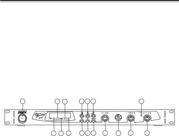
Front Panel
1 |
14 |
16 |
2 |
3 |
4 |
12 |
13 |
15 |
17 |
5 |
6 |
7 |
8 |
9 |
10 |
11 |
1.POWER switch
Switches the power on and off.
2.EDIT button
Switches between the PLAY mode and EDIT mode. The LED above will light up while in EDIT mode.
3.PROGRAM A button
Selects the PROGRAM A. While the PROGRAM A is being selected, the Main Parameter can be switched to the Sub Parameter by holding down the PROGRAM A button. Refer to the Sub Parameters in EDIT mode.
4.PROGRAM B button
Selects the PROGRAM B. While the PROGRAM B is being selected, the Main Parameter can be switched to the Sub Parameter by holding down the PROGRAM B button. Refer to the Sub Parameters in EDIT mode.
5.< button
In EDIT mode, selects the parameter.
6.> button
In EDIT mode, selects the parameter.
1

Names and functions
7.EXECUTE/STYLE EDIT button
Used to save the edited program and/or to copy the program. In EDIT mode, used to switch between the STYLE EDIT and CHORD EDIT screen (in the STYLE or CHORD mode only).
8.BANK/DATA control
In PLAY mode, selects the BANK. In EDIT mode, selects the parameter or changes the parameter value.
9.BYPASS button
Switches between the DRY sound and EFFECT sound. While it is on, the LED lights up and the DRY sound comes out. When it is connected using the XLR input and the XLR output, the input signal does not go through the internal circuit, thus the original vocal sound comes out clean without any coloration.
(True Bypass).
In EDIT mode, it is also used as SOLO function (refer to VOICE parameter in EDIT mode).
10.OUTPUT LEVEL control
Sets the output signal level.
11.INPUT LEVEL control
Sets the input signal level. Set it as high as possible in the range that the OVER (RED) LED of the Input Level Indicator will not light up.
12.Input Level Indicator
Indicates the input signal level. The OVER (RED) LED lights up when the input level is too high.
13.KEY
In PLAY mode, indicates the Key of the program (with STYLE, CHORD and MODAL mode programs only).
14.L2
In EDIT mode, indicates the status of Harmony L2.
15.L1
In EDIT mode, indicates the status of Harmony L1.
16.ORIGIN
In EDIT mode, indicates the status of Original voice.
17.H1
In EDIT mode, indicates the status of Harmony H1.
18.H2
In EDIT mode, indicates the status of Harmony H2.
2
Names and functions
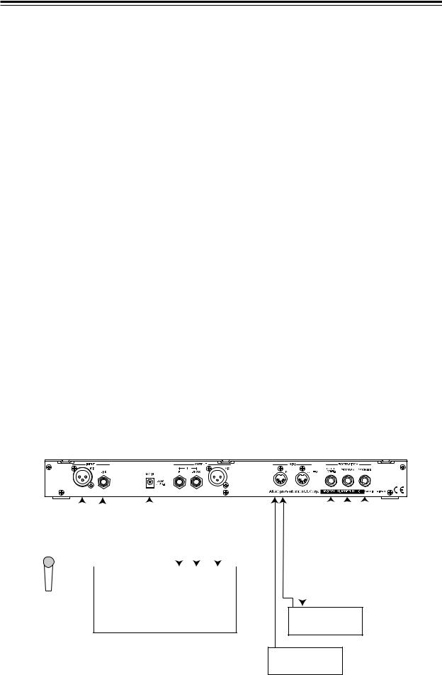
REAR PANEL
1 |
2 |
3 |
4 |
5 |
6 |
7 |
8 |
9 |
10 |
11 |
1.MIC input
Input of microphone signal level. When both the MIC input and LINE input are connected, the LINE input takes priority over the MIC input.
2.LINE input
Connects the vocal signal (Line signal level) from the microphone amplifier and/or mixer, here. When both the MIC input and LINE input are connected, the LINE input takes priority over the MIC input.
3.DC IN
Connects the proprietary AC Adaptor included.
4.LINE R output
Output of Line signal level.
5.LINE L (MONO) output
Output of line signal level.
When the LINE R output is not connected, the LINE L (MONO) output provides the L/R mixed signal.
6.MIC output
Output of microphone signal level. Connects to the microphone input terminal of the microphone amplifier and/or other mixer.
The output signal provided changes by the combination of terminals used.
When the LINE L (MONO) output and MIC output are connected at the same time (but the LINE R output is not connected),
both the LINE L (MONO) output and MIC output provide the L/R mixed signal.
When the LINE R output, LINE L (MONO) output and MIC output are connected at the same time, the LINE R output provides the Stereo R signal and both the LINE L (MONO) output and MIC output provide the Stereo L signal.
(Notes in Connection)
The LINE R output should not be used alone, but be used together with the LINE L (MONO) output. When the LINE R output is connected alone, the LINE R signal output is disabled when the BYPASS mode is switched ON.
3
Basic Operation
7.MIDI IN
Receives the MIDI signals.
8.MIDI OUT/THRU
Used as MIDI OUT or MIDI THRU terminal. The OUT or THRU mode is switched by the MIDI SYSTEM parameter setting in EDIT mode.
OUT: Transmits the MIDI signal.
THRU: Routes the MIDI IN signal through.
9.FOOTSWITCH ON/OFF (COMBI)
Connects the footswitch to control the BYPASS ON/OFF. With the Combination Pedal (Footswitch) connected, it can control the BYPASS ON/OFF and also switching between the PROGRAM A and PROGRAM B. Refer to the Footswitch Operation described later.
10.FOOTSWITCH PROGRAM A
Connects the footswitch here. Similar to the PROGRAM A button on the Front Panel, selects PROGRAM A or switches between the Main Parameter and Sub Parameter. Refer to the Footswitch Operation.
11.FOOTSWITCH PROGRAM B
Connects the footswitch here. Similar to the PROGRAM B button on the Front Panel, selects PROGRAM B or switches between the Main Parameter and Sub Parameter. Refer to the Footswitch Operation.
Connect the footswitches while the unit is turned off.
Connect the footswitches of Normal-Open type.
Basic Operation
|
|
|
|
|
|
|
|
|
|
|
|
|
|
|
|
|
|
|
|
|
|
|
|
|
|
|
|
|
|
|
|
|
|
|
|
|
|
|
|
|
|
|
|
|
|
|
|
|
|
|
|
|
|
|
|
|
|
|
|
|
|
|
|
|
|
|
AC ADAPTER |
|
|
MIC IN |
|
|
|
|
|
|
|
|
|
||||
|
|
|
|
OUTPUT |
|
INPUT |
|
|
|
|
|
|
|
|
|
|
|
|||
|
|
|
|
|
|
|
|
|
|
|
|
ON/OFF A B |
||||||||
|
|
|
|
|
|
|
|
|
|
|
|
|||||||||
|
|
|
|
|
|
|
|
|
|
|
MIDI |
|
FOOTSWITCH |
|||||||
|
MIC |
|
|
|
|
|
|
|
|
|
|
|
|
|
|
|
|
|
|
|
|
|
|
MIXER |
|
|
OUT |
MIDI IN |
|||||||||||||
|
|
|
|
|
|
|
||||||||||||||
|
|
|
|
|
|
|
|
|
||||||||||||
SEQUENCER
MIDI OUT
KEYBOARD
4

Practical Operation
1.Connect a microphone to the MIC (XLR) input terminal.
2.Connect the MIC (XLR) output terminal to the microphone input terminal of the microphone amplifier ormixer.
Note: When the LINE input/output terminals are used, connect them to the LINE output/input terminals of the mixer.
Note: Be sure to turn down the levels of the amplifier/mixer while making the connection.
3.Connect the AC Adaptor and press the POWER switch to turn the unit on.
4.When the unit is turned on, the selected BANK number, PROGRAM (A or B) and its name appear on the upper line of the screen. The part of its program parameters appear on the lower line of the screen.
5.Press the BYPASS button to turn the BYPASS off (BYPASS LED is off) and sing into the microphone. Adjust the INPUT LEVEL control to set the input level as high as possible in the range that the OVER (RED) LED of the Input Level Indicator will not light up. The output terminal provides the original vocal sound mixed with the harmonies.
6.Set the signal output level using the OUTPUT LEVEL control. Adjust the signal level appropriately on the amplifier/mixer.
7.Select the BANK using the BANK/DATA control and switch the PROGRAM with the PROGRAM A/B buttons.
BANK and PROGRAM
The DecaBuddy has 50 banks. Each bank contains two programs, i.e. PROGRAM A and PROGRAM B. There are 100 programs in total. All programs can be edited and they can be overwritten as your original programs.
Practical Operation
Using Preset Programs
Switch the bank using the BANK/DATA control and select the program with the PROGRAM A/PROGRAM B buttons.
Try switching the preset programs while singing.
Some programs produce the original vocal sound mixed with the harmony sound, while the other programs produce only the original vocal sound.
This is because of the difference in MODE, one of the parameters that make up the program. The mode, such as STYLE, MODAL, etc., is shown at the lower right side of the screen when the program is switched.
What is MODE?
The mode decides the way the harmony is generated. The DecaBuddy has 7 modes. Some generate harmonies to the original vocal sound by itself, while the others generate harmonies based on the MIDI signal received.
The following is the brief explanation of each mode and its characteristics (refer to EDIT Mode for their operation).
5
 Loading...