


JP-DA, JP-DV, JP-DVF
VIDEO DOOR STATION
POSTE DE PORTE VIDÉO
VIDEO PORTERO
VIDEODEURPOST
POSTAZIONE VIDEOCITOFONICA ESTERNA
INSTALLATION MANUAL
MANUEL D’INSTALLATION
MANUAL DE INSTALACIÓN
INSTALLATIEHANDLEIDING
MANUALE D’INSTALLAZIONE
JP-DA |
JP-DVF |
Video door station |
Vandal-resistant video door station |
Poste de porte vidéo |
Portier vidéo résistant au vandalisme |
Video portero |
Video portero antivandálico |
Videodeurpost met kunststof |
Videodeurpost met inox antivandalisme- |
opbouwbehuizing |
inbouwbehuizing |
Postazione videocitofonica |
Postazione videocitofonica esterna |
esterna |
resistente agli atti vandalici |
JP-DV |
|
Vandal-resistant video door station |
|
Portier vidéo résistant au vandalisme |
|
Video portero antivandálico |
|
Videodeurpost met metalen |
|
antivandalisme-opbehuizing |
|
Postazione videocitofonica esterna |
|
resistente agli atti vandalici |
|

English
Français
PRECAUTIONS
General Prohibitions |
Prohibition to Dismantle the Unit |
Prohibition on Subjecting the Unit to Water |
General Precautions |
 WARNING
Negligence could result in death or serious injury.
1. Do not dismantle or alter the unit. Fire or electric shock could result.
2. Existing wiring such as chime wiring, etc. may contain high voltage AC electricity. Damage to the unit or electric shock could result. Wiring and installation should be done by a qualifi ed technician.
3. This unit is not an explosion-proof unit. Do not install or use the unit in locations that are fi lled with fl ammable gas such as oxygen rooms. Fire or an explosion could result.
 CAUTION
Negligence could result in injury to people or damage to property.
1. Before turning on power, make sure wires are not crossed or shorted. If not, fi re or electric shock could result.
2. Do not install or make any wire terminations while power supply is plugged in. It can cause electrical shock or damage to the unit.
GENERAL PRECAUTIONS
1.The door station is weather resistant, but do not spray high pressure water on door station directly. Unit trouble could result.
Español
Nederlands
Italiano
PACKAGE CONTENTS
Verify that the following parts are included.
JP-DA
Front panel Main unit |
Installation manual |
|
|
|
|
JP-DV |
|
|
|
|
|
The unit |
Special screwdriver |
Transparent nameplate (x2) |
Installation manual |
||
JP-DVF |
|
|
|
|
|
|
|
Special screw (x4) |
|
|
|
|
Flush mount back box |
Hexagonal wrench |
Transparent |
|
|
The unit |
nameplate (x2) |
Installation manual |
|||
|
|||||
INSTALLATION
Mounting locations
"Do not install video door station in any of the following locations where lighting or the ambient environment could impact the display on the video monitor due to the characteristics of the door station's camera."
a Locations subject to |
b Under street lights or door |
c Other locations subject to strong |
||||||||
|
direct sunlight |
|
lights |
|
lighting or backlighting conditions |
|||||
|
|
|
|
|
|
|
|
|
|
|
|
|
|
|
|
|
|
|
|
|
|
|
|
|
|
|
|
|
|
|
|
|
|
|
|
|
|
|
|
|
|
|
|
|
|
|
|
|
|
|
|
|
|
|
|
|
|
|
|
|
|
|
|
|
|
|
|
|
|
|
|
|
|
|
|
|
|
|
|
|
|
|
|
|
|
|
|
|
|
|
|
|
|
|
|
|
|
|
2

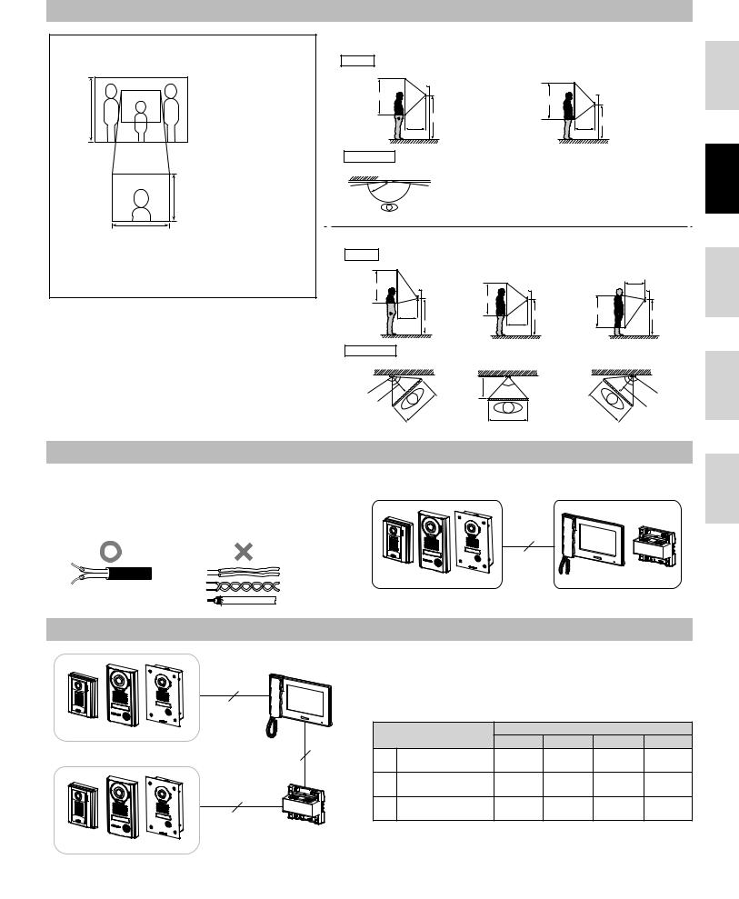
Mounting positions and image view area
Wide picture
Approx. 1,300 mm (4' 3")
Zoom picture
Objects appear smaller due to greater distortion in the surrounding sections compared to the central section, but a wider area is displayed.
The display range is a rough estimation and may change due to the installation environment.
Approx. 600 mm (2')
Approx. 950 mm (3' 1")
The zoom position can be changed.
(Refer to the master station's operation manual.) The factory setting is "Center" for Zoom mode.
Wide picture
Up/Down |
Mounting position |
||
|
|||
Approx. 2,200 mm |
1,500 mm (5') |
||
|
|
||
(7' 2") |
|
Unit center |
|
Approx. 1,300 mm (4' 3") |
|||
|
|||
Approx. 900 mm |
|
1,500 mm (5') |
|
(2' 12") |
|
||
|
|
500 mm (20") |
|
Left/Right |
|
|
|
Mounting position 1,300 mm (4' 3")
Approx. 2,000 mm |
|
|
(6' 7") |
|
|
Approx. 1,300 mm (4' 3") |
Unit center |
|
Approx. 700 mm |
1,300 mm (4' 3") |
|
(2' 4") |
||
|
||
|
500 mm (20") |
Approx. 170° An area over a range of approx. 170° in a 


 500 mm radius from the camera displays.
500 mm (20")
(The display range is a rough estimation and may change due to the installation environment.)
Zoom picture (when mounting position is 1,500 mm (5'))
Up/Down |
Zoom <Up> |
Zoom <Center> |
Zoom <Down> |
||||
Approx. 2,250 mm |
|||||||
|
|
|
|
|
|
||
(7' 5") |
|
Approx. 1,850 mm |
|
|
500 mm (20") |
||
|
|
|
|
|
|
||
Approx. 750 mm (2' 5") |
|
(6' 1") |
|
Approx. 1,550 mm |
|
||
|
|
|
|
(5' 1") |
|
||
|
|
Unit center Approx. 600 mm |
|
|
|||
|
|
Unit center |
|
Unit center |
|||
Approx. 1,500 mm |
|
|
(2') |
|
|||
(5') |
|
Approx. 1,250 mm |
|
|
Approx. 750 mm |
|
|
|
|
|
1,500 mm (5') |
(2' 5") |
1,500 mm (5') |
||
|
|
(4' 1") |
|
||||
|
|
|
|
|
|
||
|
500 mm (20") |
1,500 mm (5') |
500 mm (20") |
Approx. 800 mm |
|
||
|
|
|
|
||||
|
|
|
|
|
(2' 8") |
|
|
Left/Right |
Zoom <Left> |
Zoom <Center> |
|
Zoom <Right> |
|||
Approx. 140° |
Approx. |
Approx. 500 mm |
|
|
Approx. |
Approx. 140° |
|
|
85° |
Approx. |
|
85° |
|
||
|
|
(20") |
|
|
|
||
|
|
|
85° |
|
|
|
|
Approx. 500 mm (20") |
|
Approx. |
|
|
Approx. |
Approx. 500 mm (20") |
|
|
|
|
|
||||
|
|
950 mm (3' 1") |
|
|
950 mm (3' 1") |
|
|
Approx. 950 mm (3' 1")
English
Français
Español
Nederlands
Cable
•Use PE (polyethylene)-insulated PVC jacket cable.
Parallel or jacketed 2-conductor, mid-capacitance, non-shielded cable is recommended.
•Never use individual conductors, twisted pair cable, or coaxial cable.
Wiring distance
JP-4MED
2
[A]
JP-DA JP-DV JP-DVF
2 [C]
2
[B]


 JPW-BA JP-DA JP-DV JP-DVF
Italiano
2
JP-DA JP-DV JP-DVF |
JP-4MED JPW-BA |
|
|
|
Wire diameter |
|
|
|
|
Ø0.65 mm |
Ø0.8 mm |
Ø1.0 mm |
Ø1.2 mm |
|
|
(22 AWG) |
(20 AWG) |
(18 AWG) |
(16 AWG) |
[A] |
Door station - master |
50 m |
100 m |
100 m |
100 m |
|
station |
(165') |
(330') |
(330') |
(330') |
[B] |
Door station - long |
100 m |
150 m |
200 m |
200 m |
|
distance adaptor |
(330') |
(490') |
(650') |
(650') |
[C] |
Long distance |
50 m |
75 m |
100 m |
100 m |
|
adaptor - master |
(165') |
(245') |
(330') |
(330') |
|
station |
|
|
|
|
3
English
Français
Español
Nederlands
Italiano
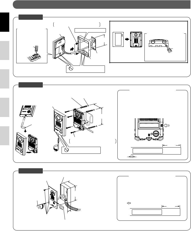
MOUNTING
JP-DA
Mounting screw × 2 (not included) Screw shaft: Ø4.1 or less
Slotted head: Ø8.2 or less, 3.0mm or less in height
Removing the |
|
main unit from the |
Main unit |
mounting frame |
|
Remove the main unit. (Loosen the locking screws.)
 Screwdriver
Tighten Loosen
Place "  UP" upwards
83.5 mm (3-5/16")
1-gang box
Mounting frame
Drainage hole
Do not block the holes.
Mount the main unit on the mounting frame, and fit the front panel on.
|
|
Removing the front panel |
|
|
|
<Bottom surface> |
|
Front panel |
Main unit |
Flathead |
|
screwdriver |
|||
|
|
||
|
|
Pry off the front panel with |
|
|
|
a flathead screwdriver. |
JP-DV
Anchor × 4 (not included) (Prepare anchors according to the size of the mounting screws.)
Vandal-resistant front panel
 Loosen
Special screwdriver
(The diameter and the depth of the holes on the wall depend on the anchors suitable for the mounting screws used.)
75 mm (3'')
150 mm (5-15/16'')
Mounting screw × 4 (not included)
Screw shaft: Ø4.1 or less
Slotted head: Ø8.2 or less, 3.0mm or less in height
Tighten
Drainage hole
Do not block the holes.
* Remove protective fi lm from camera before use.
Using the transparent nameplates
Inserting the transparent nameplates
Remove the vandal-resistant front panel.
Peel off the protective seals on the plate (both sides).
Fill in the name of the resident on the transparent nameplate.  Be sure to leave 25 mm (1") of white space on the right end to account for insertion.
Insert the fi lled-in transparent nameplate at the specifi ed insertion opening (indicated with  in diagram) as below.
Insert transparent nameplate here.
25 mm (1")

 ABC
ABC
2 mm (1/8")
JP-DVF
Vandal-resistant front panel
Hexagonal
wrench
Tighten
Special screw × 4
Flush mount back box (included)
110 mm (4-3/8'')
180 mm (7-3/32'')
45 mm (1-25/32'')
Transparent nameplate
* Remove protective fi lm from camera before use.
Using the transparent nameplates
Inserting the transparent nameplates
Remove the vandal-resistant front panel from the fl ush mount back box.
Peel off the protective seals on the plate (both sides).
Fill in the name of the resident on the transparent nameplate.  Be sure to leave 25 mm (1") of white space on the right end to account for insertion.
Insert the fi lled-in transparent nameplate at the specifi ed insertion opening on the rear side of the vandal-resistant front panel (indicated
with |
in diagram). |
25 mm |
|
|
|
|
|
(1") |

 ABC
ABC
 2 mm (1/8")
4

WIRING
A1 |
2 |
|
1A1 |
A2 |
|
NP |
1A2 |
JP-DA JP-DV JP-DVF
JP-4MED |
NP: Non-polarized |
|
TECHNICAL PRECAUTIONS
•Door station is weather resistant. However, do not spray high pressure water on door station directly. Unit trouble could result.
•Cleaning:
Clean units with a soft cloth and gentle cleaner. Do not spray cleaner directly on unit. Do not use an abrasive cleanser or cloth.
Wipe away dirt from the lens softly with a soft cloth. Observe the following points for lens care.
-Take care not to scratch the lens.
-Do not use organic solvents other than isopropyl alcohol (IPA) and methanol.
-Do not use thinner, benzene, etc. It may cause damage or discoloration to the surface of the unit.
SPECIFICATIONS
Power supply |
|
Supplied from master station |
Operating temperature |
- 10 - 60°C (+14°F - +140°F) |
|
Camera unit |
|
Complementary metal oxide semiconductor |
|
|
(CMOS) |
Scanning lines |
|
525 lines |
Minimum subject illumination |
5 Lux at 50 cm (1'6") distance |
|
Dimensions |
JP-DA |
129 (H) x 97 (W) x 30.5 (D) (mm) |
|
|
5-1/8 (H) x 3-7/8 (W) x 1-3/16 (D) (inches) |
|
JP-DV |
173 (H) x 98 (W) x 27.1 (D) (mm) |
|
|
6-13/16 (H) x 3-7/8 (W) x 1-1/16 (D) (inches) |
|
JP-DVF |
209 (H) x 135 (W) x exposed area 5.6 (D) (mm) |
|
|
8-1/4 (H) x 5-5/16 (W) x 7/32 (D) (inches) |
|
Flush mount back box |
180 (H) x 110 (W) x 45 (D) (mm) |
|
(JP-DVF) |
7-3/32 (H) x 4-3/8 (W) x 1-25/32 (D) (inches) |
Mass |
JP-DA |
Approx. 170 g (0.37 lbs.) |
|
JP-DV |
Approx. 650 g (1.43 lbs.) |
|
JP-DVF |
Approx. 570 g (1.26 lbs.) |
|
Flush mount back box |
Approx. 450 g (1.0 lbs.) |
|
(JP-DVF) |
|
English
Français
Español
Nederlands
Italiano
5

English
Français
Español
Nederlands
Italiano
PRECAUTIONS
Mesures générales d’interdiction |
Interdiction de démonter l’appareil |
Interdiction d’exposer l’appareil à l’eau |
Précautions générales |
 AVERTISSEMENT
Le non-respect de cet avertissement risque d’entraîner des blessures graves, voire mortelles.
1. Ne démontez pas et ne modifi ez pas l’unité. Vous risqueriez de provoquer un incendie ou un choc électrique.
2. Le câblage existant peut être conducteur d’électricité CA. Ceci peut endommager l’appareil et provoquer un incendie ou une décharge électrique. Faites réaliser les opérations de câblage par un technicien qualifi é.
3. Cet appareil n’est pas à l’épreuve des explosions. N’installez pas ou n’utilisez pas l’unité dans des endroits présentant des gaz infl ammables, tels que des salles à oxygène. Un incendie ou une explosion peut survenir.
 ATTENTION
Le non-respect de cet avertissement risque d’entraîner des blessures ou des dégâts matériels.
1. Avant de brancher le bloc d’alimentation, vérifi ez que les fi ls ne sont pas croisés ou en court-circuit. Dans le cas contraire, cela pourrait provoquer un incendie ou un choc électrique.
2. Ne réalisez aucune connexion de fi l lorsque l’appareil est branché, sous peine de provoquer une décharge électrique ou d’endommager l’unité.
PRÉCAUTIONS GÉNÉRALES
1.Le poste de porte est protégé contre les intempéries, cependant ne pulvérisez pas d’eau sous haute pression directement sur le poste de porte. Cela risquerait en effet de provoquer une panne de l’appareil.
CONTENU DE L’EMBALLAGE
Vérifiez que les éléments suivants sont inclus.
JP-DA
Face avant Unité principale |
Manuel d’installation |
|
|
|
|
JP-DV |
|
|
|
|
|
L’unité |
|
Etiquette porte-noms |
|
|
|
Tournevis spécial |
transparente (x2) |
Manuel d’installation |
|||
JP-DVF |
|
|
|
|
|
|
|
Vis spécial (x4) |
|
|
|
Boîtier d’encastrement |
Tournevis spécial |
Etiquette porte-noms |
|
||
L’unité |
|
transparente (x2) |
Manuel d’installation |
||
INSTALLATION
Emplacements de montage
N’installez pas le portier vidéo aux endroits repris ci-dessous où l’éclairage et l’environnement ambiant pourrait affecter l’affichage sur le moniteur vidéo intérieur.
a Endroits directement exposés |
b Sous des éclairages publics |
c Autres endroits fortement éclairés |
||||||||
|
à la lumière du soleil |
|
ou des éclairages de porte |
|
ou à contre-jour |
|||||
|
|
|
|
|
|
|
|
|
|
|
|
|
|
|
|
|
|
|
|
|
|
|
|
|
|
|
|
|
|
|
|
|
|
|
|
|
|
|
|
|
|
|
|
|
|
|
|
|
|
|
|
|
|
|
|
|
|
|
|
|
|
|
|
|
|
|
|
|
|
|
|
|
|
|
|
|
|
|
|
|
|
|
|
|
|
|
|
|
|
|
|
|
|
|
|
|
|
|
6
Positions de montage et zone de vision de l’image
Image plein écran
Environ 1 300 mm
Image Zoom
Les objets apparaissent plus petits à cause d’une plus grande distorsion dans les sections environnantes par rapport à la partie centrale, mais ainsi, une zone plus grande est affichée.
La plage d’affichage
est une estimation brute et peut varier suite à l’environnement d’installation.
Environ 600 mm
Environ 950 mm
La position du zoom peut être modifiée.
(Cf. Se reporter au manuel d’utilisation du poste maître.) Le réglage par défaut du mode Zoom est "Centré".
Image plein écran
Haut/bas Position de montage |
Position de montage |
||
Environ 2 200 mm |
1 500 mm |
|
1 300 mm |
|
Environ 2 000 mm |
|
|
|
Centre de l’unité |
|
|
Environ 1 300 mm |
|
|
|
|
Environ 1 300 mm |
Centre de l’unité |
|
|
|
||
Environ 900 mm |
1 500 mm |
Environ 700 mm |
1 300 mm |
|
|||
|
|
||
|
|
|
|
|
500 mm |
|
500 mm |
Gauche/droite
Environ 170° Une zone de couverture s’affiche, d’environ 170° 


 avec un rayon de 500 mm à partir de la caméra.
500 mm
(La plage d’affichage est une estimation brute et peut varier suite à l’environnement de l’installation.)
Image de zoom (lorsque la position de montage est de 1 500 mm)
Haut/bas |
Zoom <Haut> |
Zoom <Centre> |
|
Zoom <Bas> |
||
|
|
|||||
Environ 2 250 mm |
|
|
|
|
|
500 mm |
|
|
|
|
|
|
|
Environ 750 mm |
|
Environ 1 850 mm |
|
|
|
|
|
Centre de l’unité |
|
|
Environ 1 550 mm |
|
|
|
|
|
|
Centre de l’unité |
||
Environ 1 500 mm |
|
Environ 600 mm |
Centre de l’unité |
|||
|
|
|
|
|
|
|
|
|
Environ 1 250 mm |
1 500 mm |
Environ 750 mm |
1 500 mm |
|
|
|
|
||||
|
500 mm 1 500 mm |
500 mm |
|
Environ 800 mm |
|
|
|
|
|
|
|
||
Gauche/droite |
|
|
|
|
|
|
Zoom <Gauche> |
Zoom <Centre> |
|
Zoom <Droite> |
|||
Environ 140° |
Environ |
|
|
|
Environ |
Environ 140° |
|
85° |
Environ 500 mm |
Environ |
|
85° |
|
|
|
|
|
|
||
|
|
|
85° |
|
|
|
Environ 500 mm |
|
Environ |
|
|
Environ |
Environ 500 mm |
|
|
|
|
|||
|
|
950 mm |
|
|
950 mm |
|
Environ 950 mm
Câble
•Il est recommandé d’utiliser un câble téléphonique LYT1 8/10ème. Il est recommandé d’utiliser un câble à gaine PVC isolée PE
(polyéthylène).
• N’utilisez jamais de conducteurs individuels, de câble à paires |
|
torsadées ou de câble coaxial. |
2 |
|
JP-DA JP-DV JP-DVF 
 JP-4MED JPW-BA
English
Français
Español
Nederlands
Italiano
Longueur de câblage
JP-4MED
2
[A] |
|
|
|
|
|
|
JP-DA JP-DV JP-DVF |
|
|
Diamètre du câble |
|
||
|
Ø0,65 mm |
Ø0,8 mm |
Ø1,0 mm |
Ø1,2 mm |
||
2 [C] |
|
|||||
Poste porte - poste |
|
|
|
|
||
[A] |
maître |
50 m |
100 m |
100 m |
100 m |
|
[B] |
Poste porte - adaptateur |
100 m |
150 m |
200 m |
200 m |
|
longue distance |
||||||
2 |
Adaptateur longue |
|
|
|
|
|
[C] |
50 m |
75 m |
100 m |
100 m |
||
distance - poste maître |
||||||
[B] |
|
|
|
|
|
|
JPW-BA |
|
|
|
|
|
|
JP-DA JP-DV JP-DVF |
|
|
|
|
|
|
7

English
Français
Español
Nederlands
Italiano
MONTAGE
JP-DA
Retirer l’unité principale de son étrier
Retirez l’unité principale. (Dévissez les vis de montage).
 Tournevis
Serrer Desserrer
Vis de montage × 2 (non inclus) Diamètre de vis: Ø4,1 maximum
Tête fendue: Ø 8,2 maximum, 3,0 mm de hauteur maximum
Placez le “ HAUT”vers le haut
Unité principale
83,5 mm
Boîte simple
Etrier
Orifice de drainage
N’obstruez pas les orifices.
Montez l’unité principale sur l’étrier et fixez la face avant.
|
|
Retrait de la face avant |
|
|
|
<Surface inférieure> |
|
Face avant |
Unité principale |
Tournevis à |
|
tête plate |
|||
|
|
||
|
|
Soulevez la face avant à |
|
|
|
l’aide d’un tournevis plat. |
JP-DV
Cheville × 4 (non inclus)
(Préparez les chevilles en fonction de la taille des vis de montage.)
Platine face avant résistant au vandalisme
 Dévisser
Tournevis
spécial
(Le diamètre et la profondeur des trous dans le mur dépendent des systèmes de fixation utilisés, ces derniers devant être adaptés aux vis de montage utilisées.)
75 mm
150 mm
mm
Vis de montage × 4 (non inclus)
Diamètre de vis: Ø4,1 maximum
Tête fendue: Ø 8,2 maximum, 3,0 mm de hauteur maximum
Visser
Orifice de drainage
N’obstruez pas les orifices.
* Retirez le fi lm protecteur de la caméra avant de l’utiliser.
JP-DVF
Boîtier d’encastrement (inclus)
Face avant résistant au vandalisme
110 mm
180 mm
Tournevis spécial
Visser
45 mm
Vis spécial × 4
Etiquette porte-noms transparente
* Retirez le fi lm protecteur de la caméra avant de l’utiliser.
Utilisation des étiquettes porte-noms transparentes
Insertion des étiquettes porte-noms transparentes
Retirez la face avant résistant au vandalisme.
Détachez les joints de protection sur la plaque (les deux côtés).Ecrivez le nom du résidant sur l’étiquette porte-nom transparente.
 Assurez-vous de laisser 25 mm d’espace blanc à l’extrémité droite afi n de prendre en compte l’insertion.
Insérez l’étiquette porte-noms transparente complétée dans l’ouverture d’insertion spécifi ée (indiquée par  sur le schéma).
Insérez la plaque porte-nom transparente ici.
25 mm

 ABC
ABC
2 mm
Utilisation des étiquettes porte-noms transparentes
Insertion des étiquettes porte-noms transparentes
Retirez la face avant de la platine résistant au vandalisme du boîtier d’encastrement.
Détachez les joints de protection sur la plaque (les deux côtés).Ecrivez le nom du résidant sur l’étiquette porte-nom transparente.
 Assurez-vous de laisser 25 mm d’espace blanc à l'extrémité droite afi n de prendre en compte l'insertion.
Insérez l’étiquette porte-nom transparente remplie dans l’ouverture
d’insertion spécifi ée sur le côté arrière de la platine avant antivandale (indiquée par un  dans le schéma).
25 mm

 ABC
ABC
2 mm
8
 Loading...