

Page 1

MS
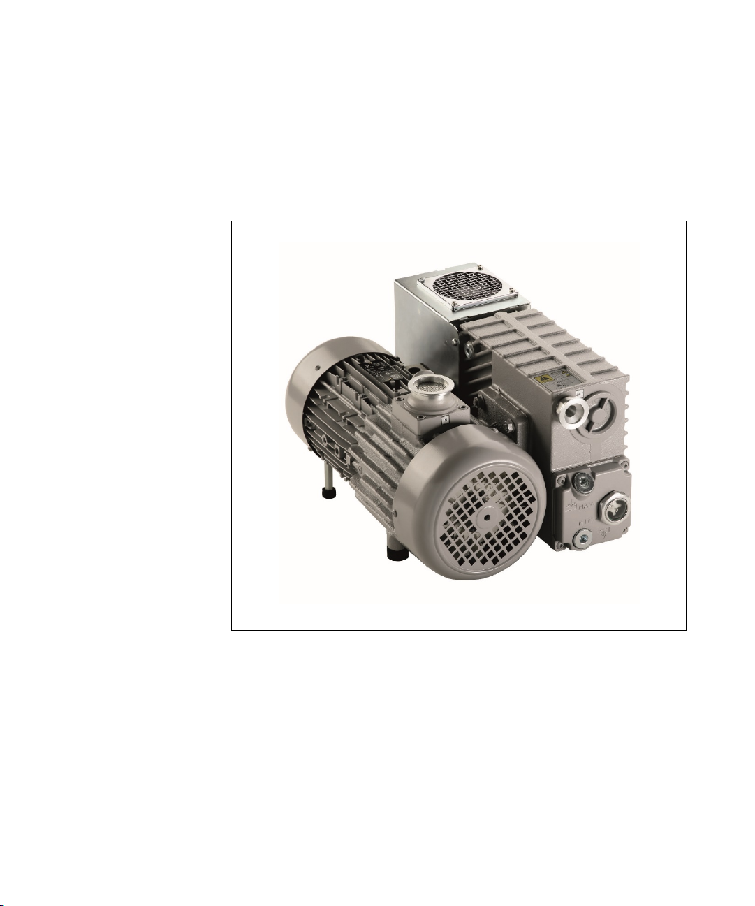
Rotary Vane Pumps
Model
949
Manuale di Istruzioni
Bedienungshandbuch
Notice de Mode D’Emploi
User Manual
40+ Single Stage
s:
9225, 9499240, 9499241
87-901-008-01 (H.00)
02/2021
Page 2

Notices
WARNING
CAUTION
© Agilent Technologies, Inc. 2021
No part of this manual may be
reproduced in any form or by any
means (including electronic storage
and retrieval or translation into a
foreign language) without prior
agreement and written consent from
Agilent Technologies, Inc. as governed
by United States and international
copyright laws.
Manual Part Number
Publication Number: 87-901-008-01 (H.00)
Edition
Edition 02/2021
Printed in ITALY
A
gilent Technologies Italia S.p.A.
Vacuum Products Division
Via F.lli Varian, 54
10040 Leinì (TO)
ITALY
Warranty
The material contained in this
document is provided “as is,” and is
subject to being changed, without
notice, in future editions. Further, to
the maximum extent permitted by
applicable law, Agilent disclaims all
warranties, either express or implied,
with regard to this manual and any
information contained herein,
including but not limited to the
implied warranties of merchantability
and fitness for a particular purpose.
Agilent shall not be liable for errors
or for incidental or consequential
damages in connection with the
furnishing, use, or performance of
this document or of any information
contained herein. Should Agilent and
the user have a separate written
agreement with warranty terms
covering the material in this
document that conflict with these
terms, the warranty terms in the
separate agreement shall control.
Technology Licenses
The hardware and/or software
described in this document are
furnished under a license and may be
used or copied only in accordance
with the terms of such license.
Restricted Rights Legend
If software is for use in the
performance of a U.S. Government
prime contract or subcontract,
Software is delivered and licensed as
“Commercial computer software” as
defined in DFAR 252.227-7014 (June
1995), or as a “commercial item” as
defined in FAR 2.101(a) or as
“Restricted computer software” as
defined in FAR 52.227-19 (June 1987)
or any equivalent agency regulation or
contract clause. Use, duplication or
disclosure of Software is subject to
Agilent Technologies’ standard
commercial license terms, and nonDOD Departments and Agencies of the
U.S. Government will receive no
greater than Restricted Rights as
defined in FAR 52.227-19(c)(1-2) (June
1987). U.S. Government users will
receive no greater than Limited Rights
as defined in FAR 52.227-14 (June
1987) or DFAR 252.227-7015 (b)(2)
(November 1995), as applicable in any
technical data.
Trademarks
Windows and MS Windows are U.S.
registered trademarks of Microsoft
Corporation.
Safety Notices
A CAUTION notice denotes a hazard.
It calls attention to an operating
procedure, practice, or the like that, if
not correctly performed or adhered to,
could result in damage to the product
or loss of important data. Do not
proceed beyond a CAUTION notice
until the indicated conditions are fully
understood and met.
A WARNING notice denotes a
hazard. It calls attention to an
operating procedure, practice, or the
like that, if not correctly performed
or adhered to, could result in
personal injury or death. Do not
proceed beyond a WARNING notice
indicated conditions are
until the
fully understood and met.
2/104 MS40+ Single Stage Rotary Vane Pumps User Manual / 87-901-008-01 (H.00)
Page 3
MS40+ Single Stage Rotary Vane Pumps
MS40+ Single Stage Rotary Vane Pumps
MS40+ Single Stage Rotary Vane Pumps User Manual / 87-901-008-01 (H.00)
3/104
Page 4

MS40+ Single Stage Rotary Vane Pumps
MS40+ Single Stage Rotary Vane Pumps User Manual / 87-901-008-01 (H.00)
4/104
Page 5

Contents
Contents
1 Istruzioni per l’uso 9
Informazioni Generali 10
Immagazzinamento 12
Preparazione per l’installazione 12
Installazione 14
Uso 17
Manutenzione 17
Smaltimento 20
2 Gebrauchsanleitung 21
Allgemeine Hinweise 22
Lagerung 24
Vor der Installation 24
Installation 26
Gebrauch 29
Wartung 29
Entsorgung 32
MS40+ Single Stage Rotary Vane Pumps User Manual / 87-901-008-01 (H.00)
5/104
Page 6

3 Mode d’emploi 34
Indications générales 35
Emmagasinage 37
Préparation pour l‘installation 37
Installation 39
Utilisation 42
Maintenance 42
Mise au rebut 45
4 Instructions for Use 47
General Information 48
Storage 50
Preparation for Installation 50
Contents
Installation 52
Use 55
Maintenance 55
Disposal 58
5 Technical Information 60
Section I 62
Technical Description 62
Vacuum Seals 63
Anti-Suckback Device 63
Technical Data 64
MS40+ Single Stage Rotary Vane
Pumps User Manual / 87-901-008-01 (H.00) 6/104
Page 7

Safety Precautions 66
Transport and Installation 66
Section II 69
Connection to the Electric Supply 69
Inlet and exhaust connections 69
Starting and Running the Pump 71
Stopping the Pump 72
Safety Rules 72
Warning Notes 73
Caution Notes 75
Maintenance Actions 76
Oil and Filter Cartridge Replacement Procedures 78
Contents
Lubricants 80
Pump Electronic Controller 83
RS 232/RS 485 Communication Description 87
Troubleshooting 94
Accessories 98
MS40+ Single Stage Rotary Vane Pumps User Manual / 87-901-008-01 (H.00)
7/104
Page 8

Contents
MS40+ Single Stage Rotary Vane
Pumps User Manual / 87-901-008-01 (H.00) 8/104
Page 9

MS40+ Single Stage Rotary Vane Pumps User Manual
1
Istruzioni per l’uso
Informazioni Generali 10
Simboli usati 11
Immagazzinamento 12
Preparazione per l’installazione 12
Installazione 14
Uso 17
Manutenzione 17
Smaltimento 20
Traduzione delle istruzioni originali
9/104
Page 10

Istruzioni per l’uso
Informazioni Generali
1
Informazioni Generali
AVVERTENZA!
Questa apparecchiatura è destinata ad uso professionale.
L'utilizzatore deve leggere attentamente il presente manuale di
istruzioni ed ogni altra informazione addizionale fornita dalla Agilent
prima dell'utilizzo dell'apparecchiatura. La Agilent si ritiene sollevata
da eventuali responsabilità dovute all'inosservanza totale o parziale
delle istruzioni, ad uso improprio da parte di personale non
addestrato, ad interventi non autorizzati o ad uso contrario alle
normative nazionali specifiche.
Le MS40+ Single Stage Rotary Vane Pumps sono delle pompe rotative
monostadio a palette, a tenuta in bagno d'olio, controllate da un'unità
elettronica.
Nei paragrafi seguenti sono riportate tutte le informazioni necessarie
a garantire la sicurezza dell'operatore durante l'utilizzo
dell'apparecchiatura. Informazioni dettagliate sono fornite
nell'appendice “Technical Information”.
Questo manuale utilizza le seguenti convenzioni:
I messaggi di avvertenza attirano l’attenzione dell’operatore su una
procedura o una pratica specifica che, se non eseguita in modo corretto,
potrebbe provocare gravi lesioni personali.
ATTENZIONE!
MS40+ Single Stage Rotary Vane Pumps User Manual / 87-901-008-01 (H.00) 10/104
NOTA
I messaggi di attenzione sono visualizzati prima di procedure che, se non
osservate, potrebbero causare danni all’apparecchiatura.
Le note contengono informazioni importanti estrapolate dal testo.
Page 11
Istruzioni per l’uso
Informazioni Generali
1
Simboli usati
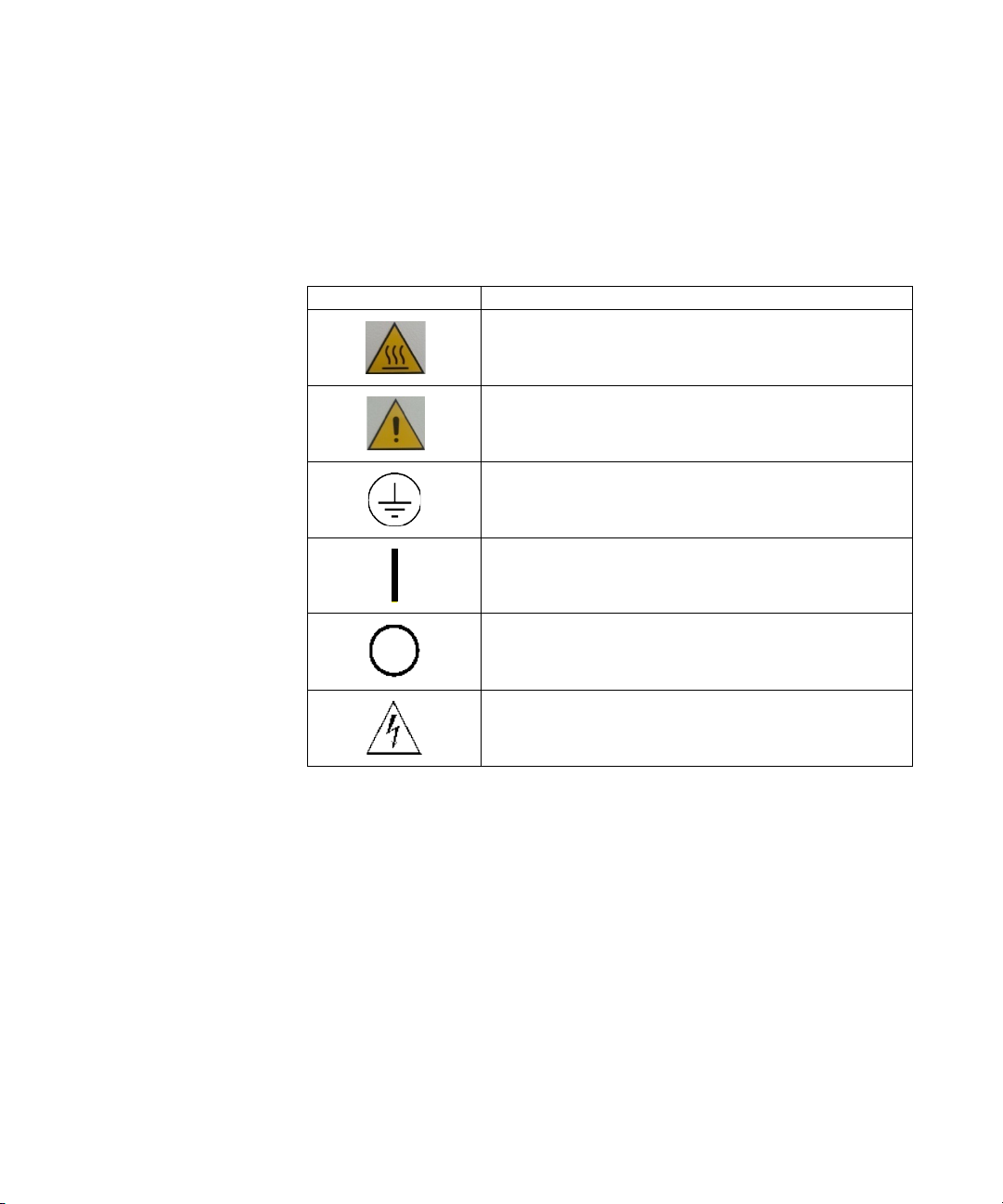
Simboli
Descrizione
I seguenti simboli sono utilizzati in modo coerente in tutte le
illustrazioni:
S
uperficie calda “Pericolo di scottature se
vengono toccate le parti calde”
P
ericolo “Vedere istruzioni di installazione/Modi
d’uso”
Conduttore di protezione (PE)
- Accensione (Alimentazione)
ON
OFF - Spegnimento (Alimentazione)
Pericolo, rischio di scossa elettrica
MS40+ Single Stage Rotary Vane Pumps User Manual / 87-901-008-01 (H.00) 11/104
Page 12

Istruzioni per l’uso
Immagazzinamento
1
Immagazzinamento
Durante il trasporto e l'immagazzinamento delle pompe non devono
essere superate le seguenti condizioni ambientali:
temperatura: da -20 °C a 70 °C
umidità relativa: 0 – 95 % (non condensante)
Preparazione per l’installazione
La pompa viene fornita in un imballo protettivo speciale; se si
presentano segni di danni, che potrebbero essersi verificati durante il
trasporto, contattare l'ufficio vendite locale.
Il peso dell’imballo, comprensivo della pompa, è, al massimo, di circa
35 kg.
Durante l'operazione di disimballaggio, prestare particolare
attenzione a non lasciar cadere la pompa e a non sottoporla ad urti o
vibrazioni.
Non disperdere l'imballo nell'ambiente. Il materiale è completamente
riciclabile e risponde alla direttiva CEE 85/399 per la tutela
dell'ambiente.
NOTA
MS40+ Single Stage Rotary Vane Pumps User Manual / 87-901-008-01 (H.00) 12/104
La pompa non può essere danneggiata rimanendo semplicemente esposta
all'atmosfera. Si consiglia comunque di mantenerla chiusa fino al momento
dell'installazione sul sistema onde evitare eventuale inquinamento da polvere.
Page 13
Istruzioni per l’uso
Preparazione per l’installazione
1
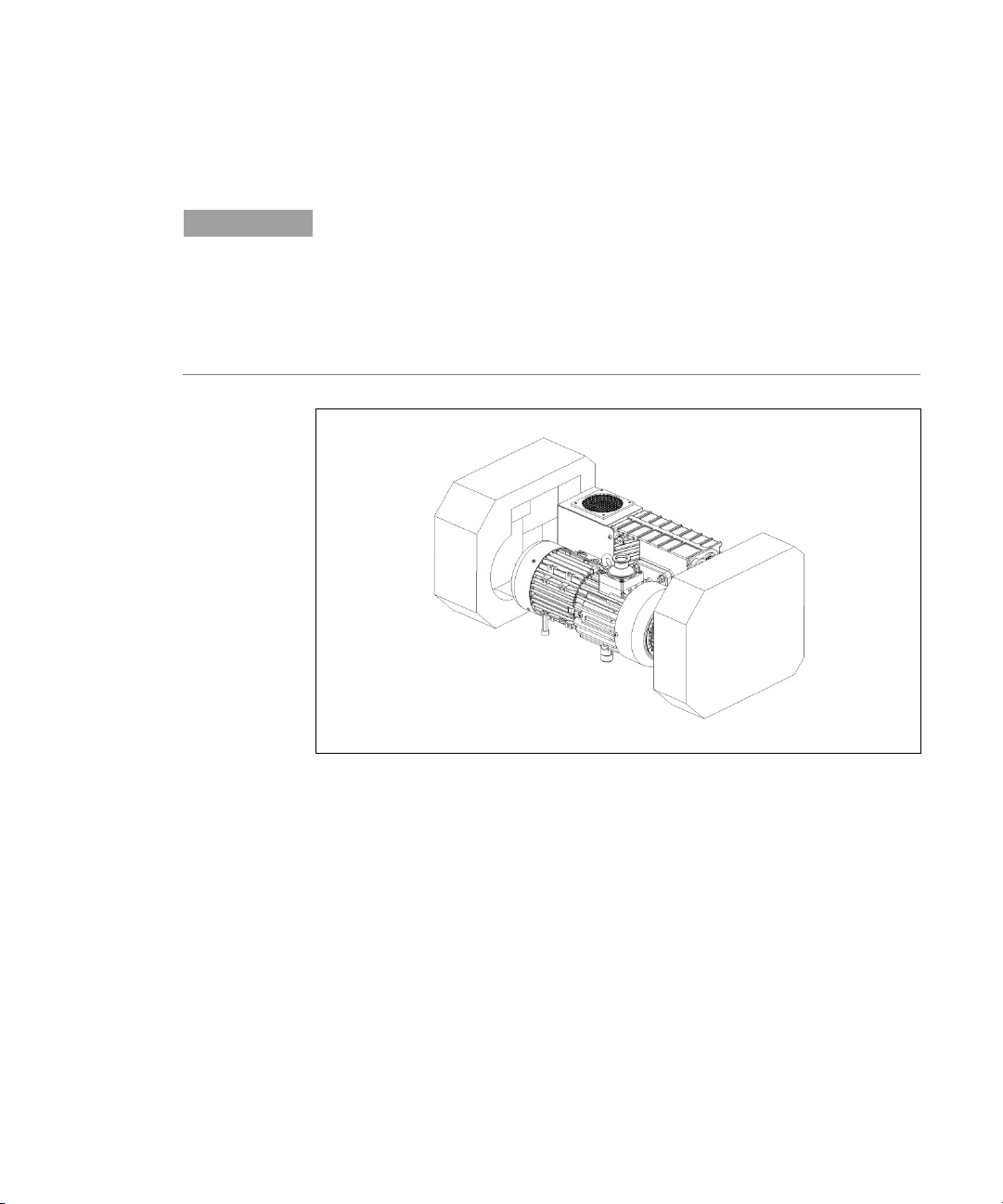
NOTA
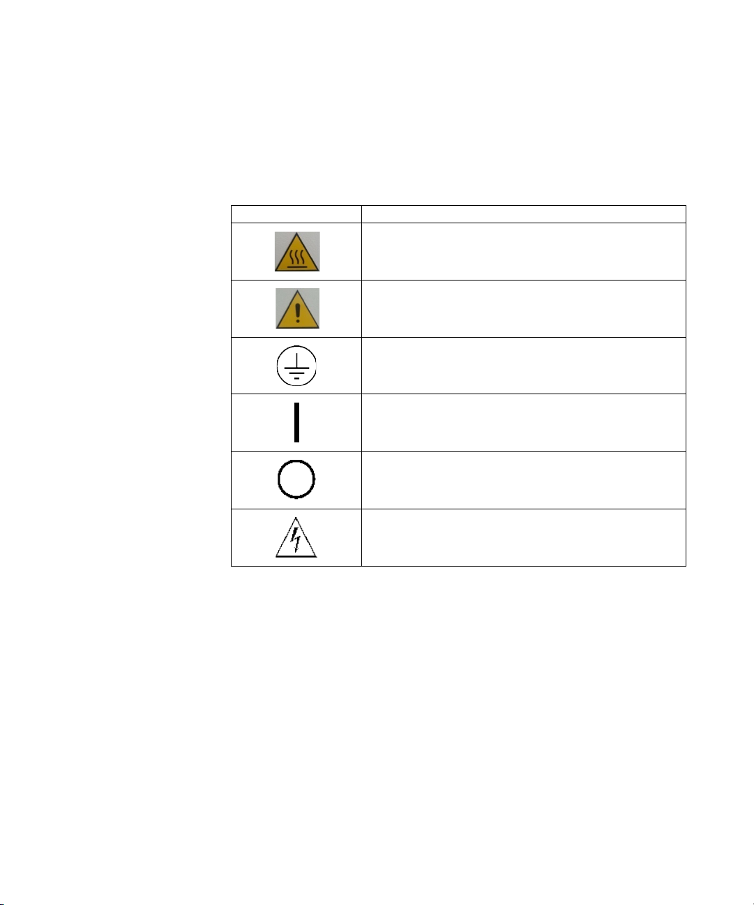
La pompa è fornita con alcuni accessori standard:
1 connettore "sub-D" a 9 contatti per I/O (femmina)
(escluso il modello 9499241)
onnettore "sub-D" a 9 contatti per RS232 (maschio)
1 c
escluso il modello 9499241)
(
Figura 1
MS40+ Single Stage Rotary Vane Pumps User Manual / 87-901-008-01 (H.00) 13/104
Page 14

Istruzioni per l’uso
Installazione
1
Installazione
AVVERTENZA!
Non installare e/o utilizzare la pompa in ambienti esposti ad agenti
atmosferici (pioggia, gelo, neve), polveri, gas aggressivi, in ambienti
esplosivi o con elevato rischio di incendio.
Durante il funzionamento è necessario che siano rispettate le
seguenti condizioni ambientali:
temperatura: da +12 °C a +40 °C
umidità relativa: 0 – 95 % (non condensante)
ATTENZIONE!
NOTA
ATTENZIONE!
Prima di avviare la pompa, occorre procedere al rifornimento di olio lubrificante,
poichè la pompa viene fornita scarica.
È importante che il livello dell’olio rimanga tra i valori MIN e MAX visualizzati
dall’indicatore di livello posto sul lato della pompa.
È obbligatorio lasciare ampio spazio libero tutto intorno alla pompa al fine di
consentire una corretta circolazione d’aria; inserire la pompa in un volume
chiuso senza ricircolo d’aria non è consentito. Per un sistema di sicurezza
interno, la pompa superata la temperatura ambiente di 40 °C, potrebbe
manifestare un errore.
Mantenere i tappi posti sulle flange di aspirazione e scarico e non accendere
la pompa finchè gli stessi non vengono appropiatamente collegati
rispettivamente allo strumento ed alla linea di exhaust.
MS40+ Single Stage Rotary Vane Pumps User Manual / 87-901-008-01 (H.00) 14/104
Page 15
Istruzioni per l’uso
Installazione
1
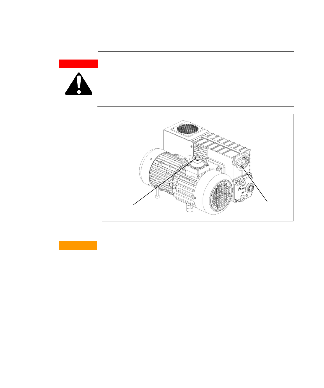
AVVERTENZA!
D
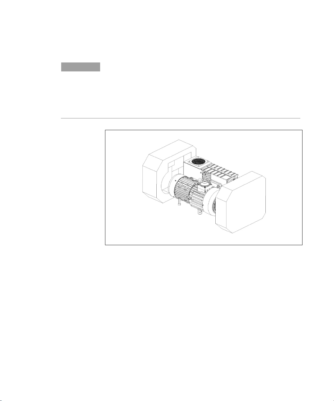
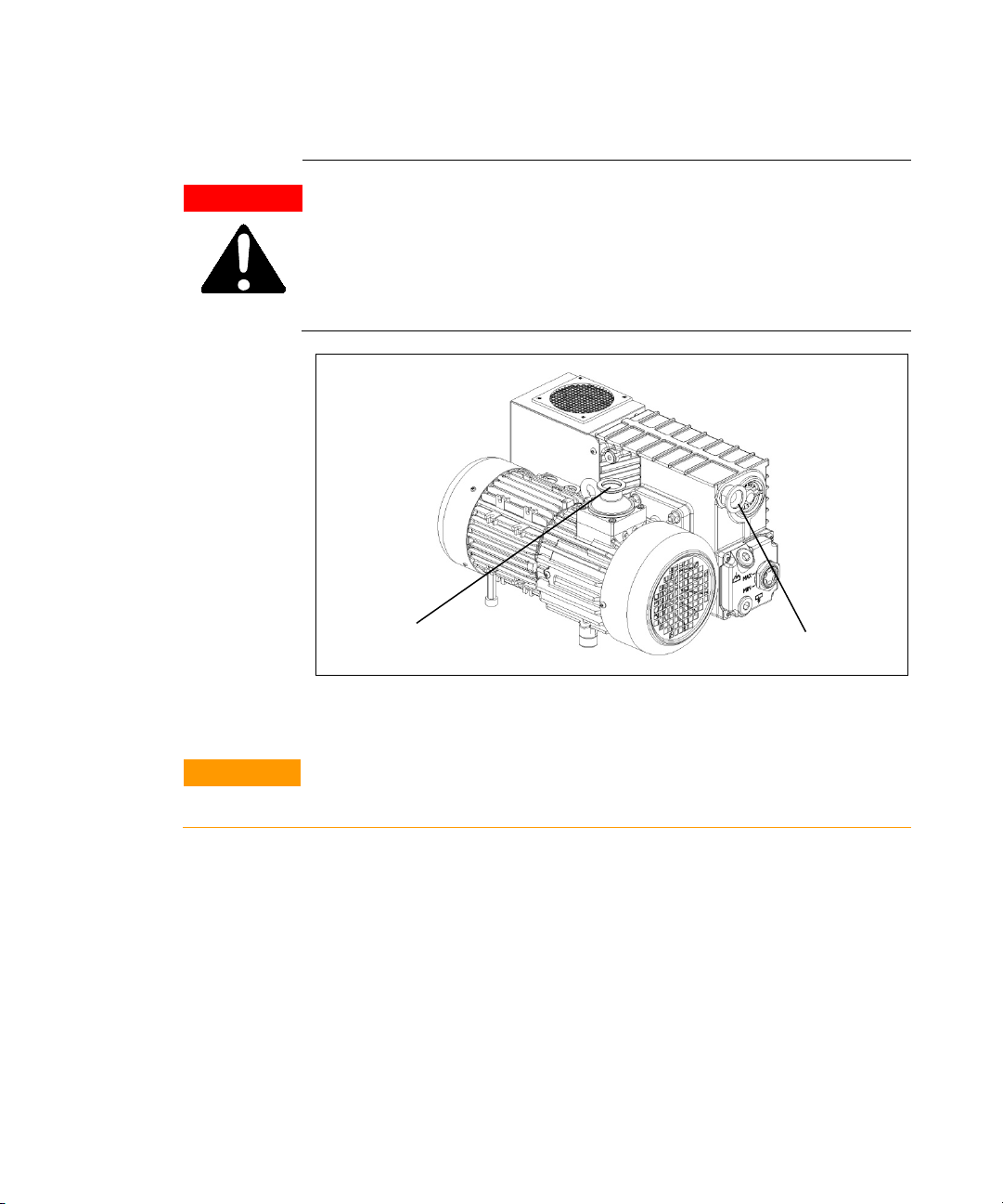
urante l'installazione, prestare la massima attenzione che la flangia di
aspirazione sia collegata alla camera da evacuare e che la flangia di scarico
non sia tappata (vedere la figura seguente). La pompa non deve essere usata
come compressore. L'inosservanza di queste precauzioni può causare danni
alla macchina ed all'operatore.
Flangia di aspirazione
Figura 2
ATTENZIONE!
MS40+ Single Stage Rotary Vane Pumps User Manual / 87-901-008-01 (H.00) 15/104
Controllare che la tensione di alimentazione corrisponda al campo di valori
indicati sui dati di targa.
Collegare la pompa all’alimentazione.
Flangia di scarico
Page 16

Istruzioni per l’uso
Installazione
1
AVVERTENZA!
La pompa deve essere installata in modo tale da permettere una facile
interruzione della linea d’alimentazione elettrica.
La pompa dev'essere utilizzata con il cavo di alimentazione fornito
insieme alla pompa (disponibile anche come accessorio).
MS40+ Single Stage Rotary Vane Pumps User Manual / 87-901-008-01 (H.00) 16/104
Page 17

Istruzioni per l’uso
Uso
1
Uso
AVVERTENZA!
AVVERTENZA!
Attivando l'interruttore di alimentazione, dopo una breve fase di
autotest, la pompa si avvia automaticamente. Per arrestarla è
necessario spegnere l'interruttore. In alternativa è possibile gestire
l'avviamento e l'arresto della pompa da remoto mediante
comunicazione seriale.
La pompa è progettata per operare con gas inerti o non corrosivi. È
assolutamente vietato l'impiego con sostanze potenzialmente esplosive o
infiammabili.
Manutenzione
Il personale addetto alla condotta ed alla manutenzione della pompa
deve essere ben addestrato e deve avere un'approfondita conoscenza
delle norme antinfortunistiche.
Le alte tensioni possono causare morte al contatto. Operare sempre con la
massima cautela e secondo le norme antinfortunistiche in vigore.
MS40+ Single Stage Rotary Vane Pumps User Manual / 87-901-008-01 (H.00) 17/104
Page 18

Istruzioni per l’uso
Manutenzione
1
AVVERTENZA!
Quando la macchina è alimentata prestare attenzione per la presenza di parti
AVVERTENZA!
AVVERTENZA!
AVVERTENZA!
in movimento e di alta tensione.
Nel caso si debba procedere ad operazioni di manutenzione della pompa al
termine di un periodo di esercizio, è necessario lasciarla raffreddare, poichè
la temperatura esterna può superare i 60 °C.
E
scludere sempre l'alimentazione della pompa prima di compiere operazioni
di manutenzione. Apporre specifici cartelli di avvertenza: APPARECCHIATURA
IN MANUTENZIONE - NON INSERIRE L'ALIMENTAZIONE, in corrispondenza
dell'interruttore di alimentazione. Al termine ripristinare i dispositivi di
sicurezza.
MS40+ Single Stage Rotary Vane Pumps User Manual / 87-901-008-01 (H.00) 18/104
Non effettuare la sostituzione dell’olio subito dopo l’arresto della macchina,
in quanto la temperatura dello stesso può essere elevata.
Page 19

Istruzioni per l’uso
Manutenzione
1
NOTA
Certification" allegata al presente manuale di istruzioni. Copia della stessa deve
Prima di rispedire al costruttore una pompa per riparazioni è indispensabile
compilare e far pervenire al locale ufficio vendite la scheda "Health and Safety
essere inserita nell'imballo della pompa prima della spedizione.
Qualora una pompa dovesse essere rottamata, procedere alla sua
eliminazione nel rispetto delle normative nazionali specifiche.
MS40+ Single Stage Rotary Vane Pumps User Manual / 87-901-008-01 (H.00) 19/104
Page 20

Istruzioni per l’uso
Smaltimento
1
Smaltimento
Significato del logo "WEEE" presente sulle etichette.
Il simbolo qui sotto riportato è applicato in ottemperanza alla
direttiva CE denominata "WEEE".
Questo simbolo (valido solo per i paesi della Comunità Europea)
indica che il prodotto sul quale è applicato, NON deve essere smaltito
insieme ai comuni rifiuti domestici o industriali, ma deve essere
avviato ad un sistema di raccolta differenziata. Si invita pertanto
l'utente finale a contattare il fornitore del dispositivo, sia esso la casa
madre o un rivenditore, per avviare il processo di raccolta e
smaltimento, dopo opportuna verifica dei termini e condizioni
contrattuali di vendita.
er maggiori informazioni riferirsi a:
P
http://www.agilent.com/environment/product/index.shtml
MS40+ Single Stage Rotary Vane Pumps User Manual / 87-901-008-01 (H.00) 20/104
Page 21

MS40+ Single Stage Rotary Vane Pumps User Manual
2
Gebrauchsanleitung
Übersetzung der Originalanleitungen
Allgemeine Hinweise 22
Verwendete Symbole 23
Lagerung 24
Vor der Installation 24
Installation 26
Gebrauch 29
Wartung 29
Entsorgung 32
21/104
Page 22

Gebrauchsanleitung
Allgemeine Hinweise
2
Allgemeine Hinweise
Dieses Gerät ist für den professionellen Gebrauch bestimmt. Vor dem
Gebrauch soll der Benutzer dieses Handbuch sowie alle weiteren von
Agilent mitgelieferten Zusatzinformationen genau lesen. Bei
vollständiger bzw. teilweiser Nichtbeachtung der enthaltenen
Hinweise, unsachgemäßem Gebrauch durch ungeschultes Personal,
nicht autorisierten Eingriffen und Benutzung unter Missachtung der
nationalen Bestimmungen übernimmt Firma Agilent keinerlei
Haftung.
Die MS40+ Single Stage Rotary Vane Pumps sind ölbadgeschmierte,
dichte, einstufige Flügelzellenpumpen, die von einer elektronischen
Steuereinheit betätigt werden
In den folgenden Abschnitten sind alle erforderlichen Informationen
für die Sicherheit des Bedieners bei der Verwendung des Geräts
aufgeführt. Detaillierte technische Informationen sind im Anhang
"Technical Information" enthalten.
In dieser Gebrauchsanleitung werden Sicherheitshinweise
folgendermaßen hervorgehoben:
WARNUNG!
VORSICHT!
HINWEIS
MS40+ Single Stage Rotary Vane Pumps User Manual / 87-901-008-01 (H.00) 22/104
Diese Warnung weist auf gefährliche Arbeitsschritte hin, die bei
unsachgemäßer Durchfüh-rung das Risiko von Personenschäden bergen.
Diese Warnung weist auf Arbeitsschritte hin, die das Risiko von Schäden am
Gerät bergen.
Die Hinweise enthalten wichtige Informationen, die aus dem Text
hervorgehoben werden.
Page 23
Gebrauchsanleitung
Allgemeine Hinweise
2
Verwendete Symbole
Symbole
Beschreibung
Folgende Symbole wurden durchgängig in allen Illustrationen
verwendet:
eiße Oberfläche –Verbrennungsgefahr bei
H
Berührung
efahr – siehe Installations- und
G
Gebrauchsanleitung
Schutzleiter (PE)
ON - Einschalten (Versorgung)
FF - Ausschalten (Versorgung)
O
Gefahr von Stromschlägen
MS40+ Single Stage Rotary Vane Pumps User Manual / 87-901-008-01 (H.00) 23/104
Page 24

Gebrauchsanleitung
Lagerung
2
Lagerung
Während des Transports und der Lagerung der Pumpen sollen die
folgenden Umgebungsbedingungen gegeben sein:
Temperatur: -20 °C bis +70 °C
Relative Feuchtigkeit: 0 – 95 % (niederschlagsfrei)
Vor der Installation
Die Pumpe wird in einer speziellen Schutzverpackung geliefert.
Eventuelle Transportschäden sind der zuständigen örtlichen
Verkaufsstelle zu melden.
Das Verpackungsgewicht beträgt, einschließlich der Pumpe, maximal
36 kg.
Beim Auspacken ist darauf zu achten, dass die Pumpe nicht
fallengelassen oder Stößen oder Vibrationen ausgesetzt wird. Das
Verpackungsmaterial ist ordnungsgemäß zu entsorgen. Es ist
vollständig recyclebar und entspricht der EG-Richtlinie 85/399 für
den Umweltschutz.
HINWEIS
MS40+ Single Stage Rotary Vane Pumps User Manual / 87-901-008-01 (H.00) 24/104
Die Pumpe kann, wenn sie einfach der Atmosphäre ausgesetzt ist, nicht
beschädigt werden. Sie sollte jedoch bis zur Installation an der Anlage
geschlossen bleiben, um Verunreinigungen durch Staub zu vermeiden.
Page 25
Gebrauchsanleitung
Vor der Installation
2
HINWEIS
Die Pumpe wird mit einigen Standardzubehörteilen geliefert:
1 9-Stift-Stecker "sub-D" für I/O (Steckbuchse
(a
ußer Modell 9499241)
1 9-Stift-Stecker "sub-D" für RS232 (Stecker)
(außer Modell 9499241)
Abbildung 1
)
MS40+ Single Stage Rotary Vane Pumps User Manual / 87-901-008-01 (H.00) 25/104
Page 26

Gebrauchsanleitung
Installation
2
Installation
Die Pumpe darf nicht in Umgebungen installiert und/oder benutzt
werden, die ungeschützt vor Witterungsbedingungen (Regen, Frost,
Schnee), Staub und aggressiven Gasen sind und in denen Explosionsoder erhöhte Brandgefahr besteht.
Während des Betriebs sollen die folgenden Umgebungsbedingungen
gegeben sein:
Temperatur: +12 °C bis +40 °C
Relative Feuchtigkeit: 0 – 95 % (niederschlagsfrei)
VORSICHT!
HINWEIS
VORSICHT!
WARNUNG!
Die Pumpe ist vor ihrer Inbetriebnahme mit Schmieröl zu füllen, da sie leer
geliefert wird.
Es ist wichtig, dass der Ölstand zwischen der MIN- und MAX-Werte auf der
Füllstandsanzeige auf der Seite der Pumpe angezeigt bleibt.
Um eine korrekte Luftzirkulation zu gewährleisten, sorgen Sie dafür, dass der
Raum um die Pumpe herum frei ist. Die Pumpe darf nicht in einem
geschlossenen Raum ohne Luftzirkulation aufgestellt werden. Wegen eines
internen Sicherheitssystems könnte die Pumpe bei Überschreiten von 40 °C
Umgebungstemperatur eine Fehlermeldung anzeigen.
Lassen Sie die Stopfen auf den Saug- und Auslassflanschen und schalten Sie
die Pumpe erst ein, wenn diese ordnungsgemäß an das Gerät bzw. an die
Auslassleitung angeschlossen wurden.
MS40+ Single Stage Rotary Vane Pumps User Manual / 87-901-008-01 (H.00) 26/104
Page 27
Gebrauchsanleitung
Installation
2
WARNUNG!
B
ei der Installation ist unbedingt darauf zu achten, dass der Saugflansch an
die zu entleerende Kammer angeschlossen ist und der Ablassflansch nicht
verschlossen ist (siehe nachstehende Abbildung). Die Pumpe darf nicht als
Verdichter verwendet werden. Bei Nichtbeachtung dieser Anweisungen
besteht Schadensgefahr für das Gerät und die Bedienperson.
Saugflansch
Abbildung 2
VORSICHT!
MS40+ Single Stage Rotary Vane Pumps User Manual / 87-901-008-01 (H.00) 27/104
Vergewissern Sie sich, dass die Versorgungsspannung in dem auf dem
Typenschild angegebenen Wertebereich liegt.
Die Pumpe an das Versorgungsnetz anschließen.
Ablassflansch
Page 28

Gebrauchsanleitung
Installation
2
WARNUNG!
Die Pumpe muss so installiert werden, dass die Stromversorgung leicht
unterbrochen werden kann.
Die Pumpe muss mit dem mitgelieferten Netzkabel (auch als Zubehör
erhältlich) betrieben werden.
MS40+ Single Stage Rotary Vane Pumps User Manual / 87-901-008-01 (H.00) 28/104
Page 29

Gebrauchsanleitung
Gebrauch
2
Gebrauch
Beim Einschalten des Netzschalters wird die Pumpe nach einer
kurzen Selbsttestphase automatisch in Betrieb genommen. Zum
Anhalten der Pumpe muss der Schalter ausgeschaltet werden.
Optional kann das Ein- und Ausschalten der Pumpe über die serielle
Kommunikation ferngesteuert werden.
WARNUNG!
Wartung
WARNUNG!
Die Pumpe ist für den Betrieb mit Inertgas oder nicht korrosiven Gasen
konzipiert. Der Einsatz mit potenziell explosions- oder feuergefährlichen
Substanzen ist streng verboten.
Das für den Betrieb und die Wartung zuständige Personal soll
geschult sein und über eine solide Kenntnis der
Unfallschutzvorschriften verfügen.
Hochspannungen können bei Kontakt tödliche Folgen haben. Es ist stets mit
größter Vorsicht und gemäß den geltenden Unfallschutzvorschriften
vorzugehen.
MS40+ Single Stage Rotary Vane Pumps User Manual / 87-901-008-01 (H.00) 29/104
Page 30

Gebrauchsanleitung
Wartung
2
WARNUNG!
Bei eingeschaltetem Gerät ist auf Bewegungs- und Hochspannungsteile zu
achten.
WARNUNG!
WARNUNG!
WARNUNG!
Falls die Pumpe im Anschluß an den Betrieb gewartet werden soll, ist
abzuwarten, bis sie abgekühlt ist, da ihre Oberfläche eine Temperatur von
60 °C überschreiten kann.
Vor Wartungsarbeiten ist die Pumpe stets energiefrei zu schalten. Am
Netzschalter sind spezielle Warnschilder “INSTANDHALTUNG AM GERÄT –
NICHT EINSCHALTEN” anzubringen. Nach Abschluss der Arbeiten sind die
Sicherheitseinrichtungen wieder zu aktivieren.
Keine Ölwechsel unmittelbar nach Stillsetzung des Gerätes vornehmen, da
die Öltemperatur sehr hoch sein kann.
MS40+ Single Stage Rotary Vane Pumps User Manual / 87-901-008-01 (H.00) 30/104
Page 31

Gebrauchsanleitung
Wartung
2
HINWEIS
Bevor dem Hersteller eine Pumpe zur Reparatur zurückgesandt wird, ist das
Formular “Sicherheit und Gesundheit” in der Anlage zum vorliegenden Handbuch
auszufüllen und der lokalen Verkaufsstelle zuzustellen. Eine Kopie des Formulars
ist der Pumpenverpackung vor dem Versand beizulegen.
Bei eventueller Verschrottung einer Pumpe ist diese entsprechend
der einschlägigen nationalen Vorschriften zu entsorgen.
MS40+ Single Stage Rotary Vane Pumps User Manual / 87-901-008-01 (H.00) 31/104
Page 32

Gebrauchsanleitung
Entsorgung
2
Entsorgung
Bedeutung des "WEEE" Logos auf den Etiketten.
Das folgende Symbol ist in Übereinstimmung mit der EU-Richtlinie
WEEE (Waste Electrical and Electronic Equipment) angebracht.
Dieses Symbol (nur in den EU-Ländern gültig) zeigt an, dass das
betreffende Produkt nicht zusammen mit Haushaltsmüll entsorgt
werden darf sondern einem speziellen Sammelsystem zugeführt
werden muss.
Der Endabnehmer sollte daher den Lieferanten des Geräts - d.h. die
Muttergesellschaft oder den Wiederverkäufer - kontaktieren, um den
Entsorgungsprozess zu starten, nachdem er die Verkaufsbedingungen
geprüft hat.
F
ür weitere Informationen:
http://www.agilent.com/environment/product/index.shtml
MS40+ Single Stage Rotary Vane Pumps User Manual / 87-901-008-01 (H.00) 32/104
Page 33

Gebrauchsanleitung
Entsorgung
2
MS40+ Single Stage Rotary Vane Pumps User Manual / 87-901-008-01 (H.00) 33/104
Page 34

MS40+ Single Stage Rotary Vane Pumps User Manual
3
Mode d’emploi
Traduction de la mode d’emploi originale
Indications générales 35
Symboles utilisés 36
Emmagasinage 37
Préparation pour l‘installation 37
Installation 39
Utilisation 42
Maintenance 42
Mise au rebut 45
34/104
Page 35

Mode d’emploi
Indications générales
3
Indications générales
AVERTISSEMENT!
Cet appareil a été conçu en vue d'une utilisation professionnelle. Il
est conseillé à l'utilisateur de lire attentivement cette notice ainsi que
toute autre information fournie par Agilent avant de l'utiliser. Agilent
décline toute responsabilité en cas de non-respect total ou partiel des
instructions fournies, d'utilisation incorrecte de la part du personnel
non formé, d'opérations non autorisées ou d'un emploi contraire aux
réglementations nationales spécifiques.
Les MS40+ Single Stage Rotary Vane Pumps sont des pompes
rotatives monoétages, à palettes, étanches en bain d'huile, contrôlées
par une unité électronique.
Les paragraphes suivants fournissent toute l‘information nécessaire
pour garantir la sécurité de l'opérateur pendant l'utilisation de
l'appareil. Des renseignements plus détaillés se trouvent dans
l'appendice «Technical Information».
Cette notice utilise les signes conventionnels suivants:
Les messages d’avertissement attirent l'attention de l'opérateur sur une
procédure ou une manœuvre spéciale dont la mauvaise exécution risque de
provoquer de graves lésions.
ATTENTION!
NOTE
MS40+ Single Stage Rotary Vane Pumps User Manual / 87-901-008-01 (H.00) 35/104
Les messages d'attention apparaissent avant certaines procédures dont le nonrespect pourrait endommager sérieusement l'appareil.
Les notes contiennent des renseignements importants, isolés du texte.
Page 36

Mode d’emploi
Indications générales
3
Symboles utilisés
Symboles
Description
Les symboles suivants sont utilisés dans les différentes illustrations:
S
urface chaude “Risque de brûlure en cas de
contact”
Da
nger “Voir instructions d’installation/Mode
d’emploi”
Conducteur de protection (Terre)
ON - Marche (Alimentation)
FF - Arrêt (Alimentation)
O
Danger, risque d’électrisation
MS40+ Single Stage Rotary Vane Pumps User Manual / 87-901-008-01 (H.00) 36/104
Page 37

Mode d’emploi
Emmagasinage
3
Emmagasinage
Pendant le transport et l'emmagasinage des pompes, veiller à
respecter les conditions environnementales suivantes:
température: de -20 °C à +70 °C
humidité relative: 0 – 95 % (sans condensation)
Préparation pour l‘installation
La pompe est fournie dans un emballage de protection spécial; si l'on
constate des marques de dommages pouvant s'être produites pendant
le transport, contacter aussitôt le bureau de vente local.
Le poids total de l'emballage avec la pompe est d’environ 35 kg
maximum.
Pendant l'opération d'ouverture de l'emballage, veiller tout
particulièrement à ne pas laisser tomber la pompe et à ne lui faire
subir aucun choc ni aucune vibration.
Ne pas jeter l'emballage dans la nature. Le matériel est entièrement
recyclable et il est conforme à la directive CEE 85/399 en matière de
protection de l'environnement.
NOTE
MS40+ Single Stage Rotary Vane Pumps User Manual / 87-901-008-01 (H.00) 37/104
La pompe ne peut être endommagée en restant simplement exposée à
l'atmosphère. Il est de toute façon conseillé de la garder dans son emballage
jusqu'au moment de sa mise en place sur le système afin d'éviter toute
pollution due à la poussière.
Page 38

Mode d’emploi
Préparation pour l‘installation
3
NOTE
La pompe est équipée de certains accessoires standard:
1 connecteur “sub-D” à 9 broches pour E/S (femelle
(e
xclus le modèle 9499241)
1 connecteur “sub-D” à 9 broches pour RS232 (mâle)
(exclus le modèle 9499241)
Figure 1
)
MS40+ Single Stage Rotary Vane Pumps User Manual / 87-901-008-01 (H.00) 38/104
Page 39

Mode d’emploi
Installation
3
Installation
AVERTISSEMENT!
Ne pas installer et/ou utiliser la pompe dans des milieux exposés aux
agents atmosphériques (pluie, gel, neige), à des poussières, à des gaz
agressifs ainsi que dans des milieux explosifs ou à risque élevé
d'incendie.
Pendant le fonctionnement, il est nécessaire de respecter les
conditions environnementales suivantes:
Température: de +12 °C à +40 °C
Humidité relative: 0 – 95 % (sans condensation)
ATTENTION!
NOTE
ATTENTION!
Avant toute utilisation de la pompe, il est impératif de procéder à son
remplissage en huile de lubrification car elle est livrée vide.
Il est important que le niveau d'huile reste entre les valeurs MIN et MAX
affichée sur l'indicateur de niveau sur le côté de la pompe.
Il est obligatoire de laisser un vaste espace libre tout autour de la pompe pour
permettre à l’air de circuler correctement ; il est interdit de monter la pompe
dans un lieu clos sans renouvellement de l’air. Du fait de la présence d’un
système de sécurité interne à la pompe, il se peut qu’une erreur se déclenche si
la température ambiante dépasse 40 °C.
Laisser les bouchons en place sur les brides d'aspiration et de vidange et ne
pas mettre la pompe en marche tant que ceux-ci n’ont pas été raccordés
respectivement à l’instrument et à la ligne d’évacuation (exhaust).
MS40+ Single Stage Rotary Vane Pumps User Manual / 87-901-008-01 (H.00) 39/104
Page 40

Mode d’emploi
Installation
3
AVERTISSEMENT!
P
Vérifier que la tension d’alimentation correspond à la plage de valeurs reportées
endant l'installation, faire très attention à ce que la bride d'aspiration soit
reliée à la chambre à vider et que la bride de vidange ne soit pas bouchée
(voir la figure ci-après). La pompe ne doit pas être utilisée comme un
compresseur. Le non-respect de ces précautions peut entraîner un danger
pour l'opérateur et endommager la machine.
Bride d'aspiration
Figure 2
ATTENTION!
sur la plaque des données techniques.
Brancher la pompe à la source d'alimentation.
MS40+ Single Stage Rotary Vane Pumps User Manual / 87-901-008-01 (H.00) 40/104
Bride de vidange
Page 41

Mode d’emploi
Installation
3
AVERTISSEMENT!
La pompe doit être installée de manière à permettre une interruption facile
du circuit d’alimentation électrique.
La pompe doit être utilisée avec le câble d’alimentation fourni en
même temps que la pompe (disponible également comme accessoire).
MS40+ Single Stage Rotary Vane Pumps User Manual / 87-901-008-01 (H.00) 41/104
Page 42

Mode d’emploi
Utilisation
3
Utilisation
AVERTISSEMENT!
AVERTISSEMENT!
Une fois l’interrupteur d’alimentation activé, la pompe démarre
automatiquement après une brève phase d’autotest. Pour l’arrêter, il
faut actionner l’interrupteur. A la place, il est possible de gérer la
mise en marche et l’arrêt de la pompe à distance par le biais d’une
communication série.
La pompe est conçue pour fonctionner avec des gaz inertes ou non corrosifs.
L'emploi de substances potentiellement explosives ou inflammables est
strictement interdit.
Maintenance
Le personnel chargé de la conduite et de la maintenance de la pompe
doit avoir la formation nécessaire et posséder une connaissance
approfondie des normes de prévention des accidents du travail.
MS40+ Single Stage Rotary Vane Pumps User Manual / 87-901-008-01 (H.00) 42/104
Les hautes tensions peuvent entraîner la mort par contact. Veiller à toujours
opérer avec le maximum de prudence et dans le respect des normes de
prévention des accidents du travail en vigueur.
Page 43

Mode d’emploi
Maintenance
3
AVERTISSEMENT!
Lorsque la machine est sous tension, faire attention à la présence d'organes
AVERTISSEMENT!
AVERTISSEMENT!
AVERTISSEMENT!
en mouvement et de haute tension.
En cas de nécessité de procéder à des opérations de maintenance de la
pompe au terme d'une période de fonctionnement, il est indispensable de la
laisser refroidir car sa température extérieure peut être supérieure à 60 °C.
A
vant toute opération de maintenance, il est impératif de toujours couper
l'alimentation de la pompe. Placer les panneaux spécifiques d'avertissement:
APPAREIL EN COURS DE MAINTENANCE – NE PAS BRANCHER
L'ALIMENTATION, près de l'interrupteur d'alimentation. Au terme des
opérations de maintenance, restaurer les dispositifs de sécurité.
Ne pas effectuer la substitution d'huile immédiatement après l'arrêt de la
machine car la température de celle-là peut être élevée.
MS40+ Single Stage Rotary Vane Pumps User Manual / 87-901-008-01 (H.00) 43/104
Page 44

Mode d’emploi
Maintenance
3
NOTE
indispensable de remplir et d'adresser au bureau local de vente la fiche “Health
Avant de retourner une pompe au constructeur pour réparation, il est
and Safety Certification” jointe à la présente notice. Une copie de celle-ci devra
être mise dans l'emballage de la pompe avant expédition.
En cas de mise au rebut de la pompe, procéder à son élimination
conformément aux réglementations nationales en la matière.
MS40+ Single Stage Rotary Vane Pumps User Manual / 87-901-008-01 (H.00) 44/104
Page 45

Mode d’emploi
Mise au rebut
3
Mise au rebut
Signification du logo "WEEE" figurant sur les étiquettes.
Le symbole ci-dessous est appliqué conformément à la directive CE
nommée "WEEE".
Ce symbole (uniquement valide pour les pays de la Communauté
européenne) indique que le produit sur lequel il est appliqué NE doit
PAS être mis au rebut avec les ordures ménagères ou les déchets
industriels ordinaires, mais passer par un système de collecte
sélective.
Après avoir vérifié les termes et conditions du contrat de vente,
l’utilisateur final est donc prié de contacter le fournisseur du
dispositif, maison mère ou revendeur, pour mettre en œuvre le
processus de collecte et mise au rebut.
P
our plus d’informations, rendez-vous à l’adresse:
http://www.agilent.com/environment/product/index.shtml
MS40+ Single Stage Rotary Vane Pumps User Manual / 87-901-008-01 (H.00) 45/104
Page 46

Mode d’emploi
Mise au rebut
3
MS40+ Single Stage Rotary Vane Pumps User Manual / 87-901-008-01 (H.00) 46/104
Page 47

MS40+ Single Stage Rotary Vane Pumps User Manual
4
Instructions for Use
Original Instructions
General Information 48
Symbols used 49
Storage 50
Preparation for Installation 50
Installation 52
Use 55
Maintenance 55
Disposal 58
47/104
Page 48

Instructions for Use
General Information
4
General Information
This equipment is destined for use by professionals. The user should
read this instruction manual and any other additional information
supplied by Agilent before operating the equipment. Agilent will not be
held responsible for any events occurring due to non-compliance, even
partial, with these instructions, improper use by untrained persons,
non-authorized interference with the equipment or any action contrary
to that provided for by specific national standards.
MS40+ Single Stage Rotary Vane Pumps are single-stage oil-sealed rotary
vane pumps controlled by an electronic module.
These high vacuum pumps are suitable for pumping non corrosive gases.
The following paragraphs contain all the information necessary to
guarantee the safety of the operator when using the equipment. Detailed
information is supplied in the appendix "Technical Information".
This manual uses the following standard protocol:
WARNING!
CAUTION!
NOTE
MS40+ Single Stage Rotary Vane Pumps User Manual / 87-901-008-01 (H.00) 48/104
The warning messages are for attracting the attention of the operator to a
particular procedure or practice which, if not followed correctly, could lead to
serious injury.
The caution messages are displayed before procedures which, if not followed,
could cause damage to the equipment.
The notes contain important information taken from the text.
Page 49

Instructions for Use
General Information
4
Symbols used
Symbols
Description
The following symbols are used consistently throughout in all
illustration:
C
aution, hot surface: “Danger of burns if hot
parts are touched”
Wa
rning “see installation/operating mode
instruction”
Protective conductor terminal
ON - Power on (Power Supply)
FF - Power off (Power Supply)
O
Caution, risk of electric shock
MS40+ Single Stage Rotary Vane Pumps User Manual / 87-901-008-01 (H.00) 49/104
Page 50

Instructions for Use
Storage
4
Storage
When transporting and storing the pumps, the following
environmental requirements should not be exceeded:
temperature: from -20° to +70 °C
relative humidity: 0 – 95 % (non-condensing)
Preparation for Installation
The pump is supplied in a special protective packing. If this shows
signs of damage which may have occurred during transport, contact
your local sales office.
Total weight of the pack, including the pump, is approx. 35 kg.
When unpacking the pump, be sure not to drop it and avoid any kind
of sudden impact or shock vibration to it.
Do not dispose of the packing materials in an unauthorized manner.
The material is 100 % recyclable and complies with EEC Directive
85/399.
NOTE
MS40+ Single Stage Rotary Vane Pumps User Manual / 87-901-008-01 (H.00) 50/104
Normal exposure to the environment cannot damage the pump. Nevertheless, it
is advisable to keep it closed until it is installed in the system, thus preventing
any form of pollution by dust.
Page 51

Instructions for Use
Preparation for Installation
4
NOTE
The pump is provided with some standard accessories:
1 9 pin "sub-D" connector for I/O (female) (excluding model 9499241)
1 9 pin "sub-D" connector for RS232 (male) (excluding model 9499241)
Figure 1
MS40+ Single Stage Rotary Vane Pumps User Manual / 87-901-008-01 (H.00) 51/104
Page 52

Instructions for Use
Installation
4
Installation
Do not install or use the pump in an environment exposed to
atmospheric agents (rain, snow, ice), dust, aggressive gases, or in
explosive environments or those with a high fire risk. During
operation, the following environmental conditions must be respected:
temperature: from +12 °C to +40 °C
relative humidity: 0 – 95 % (non-condensing).
CAUTION!
NOTE
CAUTION!
WARNING!
Before starting the pump, fill up with lubricating oil as the pump is delivered
empty.
It is important that the oil level stays within the range MIN and MAX that is
indicated by the level gauge on the side of the pump.
It is mandatory to leave ample free space all around the pump to allow for
correct air circulation; it is forbidden to insert the pump into a closed space
that restricts air circulation. The internal security system may notify of an
error condition when the environmental operating temperature of the
pump exceeds 40 °C.
Keep the caps in place on the suction and exhaust flanges and do not switch
the pump on until the flanges are appropriately connected respectively to the
exhaust instrument and to the exhaust line.
MS40+ Single Stage Rotary Vane Pumps User Manual / 87-901-008-01 (H.00) 52/104
Page 53

Instructions for Use
Installation
4
WARNING!
Outlet Flange
During installation, pay maximum attention that the suction flange is
connected to the vacuum chamber and the exhaust flange is not closed (see
the following figure). The pump must not be used as a compressor.
Non-observance of these precautions may be dangerous for the machine
and the operator.
Inlet Flange
Figure 2
CAUTION!
MS40+ Single Stage Rotary Vane Pumps User Manual / 87-901-008-01 (H.00) 53/104
Check that your electrical mains voltage corresponds to the range indicated on
on the data plate.
Connect the pump to the power supply.
Page 54

Instructions for Use
Installation
4
WARNING!
The pump must be installed in a way that allows an easy interruption of the
line voltage.
e pump must be used with the power supply cable supplied with
Th
the pump (available also as an accessory).
MS40+ Single Stage Rotary Vane Pumps User Manual / 87-901-008-01 (H.00) 54/104
Page 55

Instructions for Use
Use
4
Use
On turning the power switch on, a brief autotest phase is executed,
after which the pump starts to run automatically. To stop the pump,
turn off the power switch. As an alternative, pump starting and
stopping can be controlled remotely over a serial connection.
WARNING!
The pump is designed to operate with inert or non-corrosive gases. It is
categorically forbidden to use it with potentially explosive or flammable
substances.
Maintenance
Personnel responsible for pump operation and maintenance must be
well-trained and must be aware of the accident prevention rules.
WARNING!
Death may result from contact with high voltages. Always take extreme care
and observe the accident prevention regulations in force.
MS40+ Single Stage Rotary Vane Pumps User Manual / 87-901-008-01 (H.00) 55/104
Page 56

Instructions for Use
Maintenance
4
WARNING!
When machine is powered take care on account of moving parts and high
voltages.
WARNING!
WARNING!
WARNING!
If you have to perform maintenance on the pump after a considerable time in
operation, leave it to cool as temperature of the outer surface may be in
excess of 60 °C.
Always disconnect the power supply to the pump before starting maintenance
work. Place a special warning signs over the power supply breaker switch:
MACHINE UNDERGOING MAINTENANCE - DO NOT POWER ON. When
finished, remove the safety warning.
Do not change the oil immediately after stopping the machine as the oil
temperature may still be high.
MS40+ Single Stage Rotary Vane Pumps User Manual / 87-901-008-01 (H.00) 56/104
Page 57

Instructions for Use
Maintenance
4
NOTE
Before returning the pump to the constructor for repairs the "Health and Safety
Certification" sheet attached to this instruction manual must be filled-in and
sent to the local sales office. A copy of the sheet must be inserted in the pump
package before shipping.
If a pump is to be scrapped, it must be disposed of in accordance
with the specific national standards.
MS40+ Single Stage Rotary Vane Pumps User Manual / 87-901-008-01 (H.00) 57/104
Page 58

Instructions for Use
Disposal
4
Disposal
Meaning of the "WEEE" logo found in labels
The following symbol is applied in accordance with the EC WEEE
(Waste Electrical and Electronic Equipment) Directive. This symbol
(valid only in countries of the European Community) indicates that
the product it applies to must NOT be disposed of together with
ordinary domestic or industrial waste but must be sent to a
differentiated waste collection system.
The end user is therefore invited to contact the supplier of the device,
whether the Parent Company or a retailer, to initiate the collection
and disposal process after checking the contractual terms and
conditions of sale.
or more information refer to:
F
http://www.agilent.com/environment/product/index.shtml
MS40+ Single Stage Rotary Vane Pumps User Manual / 87-901-008-01 (H.00) 58/104
Page 59

Instructions for Use
Disposal
4
MS40+ Single Stage Rotary Vane Pumps User Manual / 87-901-008-01 (H.00) 59/104
Page 60

MS40+ Single Stage Rotary Vane Pumps User Manual
5
Technical Information
Technical Data
Preliminary Operatio
Section I 62
Technical Description 62
Vacuum Seals 63
Anti-Suckback Device 63
64
Dimensions 65
Safety Precautions 66
Transport and Installation 66
ns 68
Section II 69
Connection to the Electric Supply 69
Inlet and exhaust connections 69
Starting and Running the Pump 71
Stopping the Pump 72
Safety Rules 72
Warning Notes 73
Caution Notes 75
Maintenance Actions 76
Oil and Filter Cartridge Replacement Procedures 78
Oil Change Procedure 78
Filter Cartridge Replacement Procedure 79
Lubricants 80
AVF 60 Gold Oil Description 82
Original Instructions
60/104
Page 61

Technical Information
Disposal
5
ump Electronic Controller 83
P
T
echnical Specifications 83
nput/Output Communications 85
I
P1 – I/
O 85
RS 232/RS 485 Communication Description 87
– Serial Port 87
J1
C
ommunication Format 87
indow Protocol Description 88
W
E
xamples 90
Window Meanings 91
perational Limits 93
O
Sta
tus LED 93
Troubleshooting 94
Electronic Self-Test 94
Rotor Lock Test 97
Oil Level Check 97
Accessories 98
Original Instructions
MS40+ Single Stage Rotary Vane Pumps User Manual / 87-901-008-01 (H.00) 61/104
Page 62

Technical Information
Section I
5
Section I
Technical Description
The MS40+ Single Stage Rotary Vane Pumps are rotary vane pumps
oil sealed, driven by an electrical motor.
Figure 3
These vacuum pumps are suitable for pumping non corrosive gases.
The main features are:
all parts in direct contact with the fluid pumped are free of
copper alloys;
all materials are carefully selected to provide extended life;
due to its design features and low number of gaskets, the pump
requires little maintenance, disassembly and reassemble are easy
and require minimal time.
The oil guarantees perfect sealing of the discharge valves, enters the
pump to ensure lubrication and sealing of the parts inside, facilitates
heat dissipation and reduces pump noise.
MS40+ Single Stage Rotary Vane Pumps User Manual / 87-901-008-01 (H.00) 62/104
Page 63

Technical Information
Vacuum Seals
5
Th
e pump is equipped with a special anti-suckback device which
automatically isolates the vacuum system when the pump stops. This
avoids rises in pressure or oil flow in the vacuum system.
Vacuum Seals
A special feature of this pump is the low number of gaskets that are
employed.
The seals in the circuit are obtained by means of FKM gaskets.
Sealing of the rotor shaft is guaranteed by a rotating gasket with
dust-guard lip.
The suction flange and duct are sealed by mean of OR gaskets.
Anti-Suckback Device
The pump is equipped with a special anti-suckback device to avoid
air pressure rises and/or oil back-flow towards the evacuated
chamber when the pump is switched off. This device has a shutter
which automatically closes the suction duct.
In this way the pump and vacuum system are completely isolated
from each other and air can enter the pump without any risk for the
vacuum produced in the system.
The device includes some special features, namely:
drive obtained avoiding any form of contamination of the inlet
duct by fluids (oil and/or air). Thanks to this, when the pump is
started again, the pumpdown to vacuum conditions is extremely
fast as these contaminants are not present and no degassing is
therefore required.
MS40+ Single Stage Rotary Vane Pumps User Manual / 87-901-008-01 (H.00) 63/104
Page 64

Technical Information
Technical Data
5
Technical Data
NOISE LEVEL
dB(A)
Pollution degree
2
Max Altitude 2000m
The following table lists the main technical data of the MS40+ Single
Stage Rotary Vane Pumps.
Tab. 1
TECHNICAL DATA RPM UNITS 9499225 9499240 9499241
PUMPING SPEED (at 5 mbar inlet pressure) 1450 m3/h 40 40 40
ULTIMATE TOTAL PRESSURE * mbar 5x10
OIL CAPACITY min/max l 1 1 1
ROTATIONAL FREQUENCY min/max Hz 40-60 40-60 40-60
IP Value 20
Installation category II
OPERATING TEMPERATURE RANGE °C 12 – 40 12 – 40 12 – 40
WEIGHT Kg 33 33 33
lb 72.7 72.7 72.7
INLET FLANGE DN 25KF 40KF 40KF
EXHAUST FLANGE DN 25KF 25KF 25KF
Main Dimensions:
- length mm 418 418 418
- width mm 297 297 297
- height mm 228 228 228
Nominal Input Voltage V 200-240 200-240 200-240
Input frequency Hz 50 / 60 50 / 60 50 / 60
Max input power VA 1200 1200 1200
Indoor Use Only
-2
≤ 62 ≤ 62 ≤ 62
5x10
-2
5x10⁻²
MS40+ Single Stage Rotary Vane Pumps User Manual / 87-901-008-01 (H.00) 64/104
* According to PNEUROP 6602
** At ultimate total pressure, 20 °C (68 °F) room temperature
Page 65

Technical Information
Technical Data
5
Dimensions
Electric motor
Electronic controller
Pumping block
The following figure shows the pumps layout and dimensions:
Outlet flange
Air filter
Oil level indicator
Inlet flange
Figure 4 MS40+ Single Stage Rotary Vane Pumps layout
Figure 5 MS40+ Single Stage Rotary Vane Pumps dimensions
MS40+ Single Stage Rotary Vane Pumps User Manual / 87-901-008-01 (H.00) 65/104
Page 66

Technical Information
Safety Precautions
5
Safety Precautions
If the equipment is used in a manner not specified by the
manufacturer, the protection provided by the equipment may be
impaired.
Always carry the pump by means of the ring-bolt provided.
The pump must be set in position taking the upmost care in order
to avoid accidental falls.
WARNING!
In case of a need to handle the pump after a period of operation, it must be
left to cool first as the external surface temperature may be in excess of
60 °C.
Transport and Installation
The pumps are shipped to the customer inside cardboard boxes.
Total weight of the pack, including the pump, is about 35 Kg.
The case must be handled with care, using appropriate lifting
equipment.
CAUTION!
When moving the case, ensure that it is securely bound to the lifting equipment
and that the equipment is strong enough to support the weight.
The pump’s working environment is a traditional industrial
environment. Naturally sites with corrosive vapors or excessive heat
are best avoided.
Room temperature should ideally be between 12 °C and 40 °C.
If the temperature is not inside this range, consult Agilent technical
service for the changes required.
MS40+ Single Stage Rotary Vane Pumps User Manual / 87-901-008-01 (H.00) 66/104
Page 67

Technical Information
Transport and Installation
5
etting the pump in position should be performed as follows:
S
Pump laid on the ground. There are no special instructions for
this type of installation, except that the floor should be as flat as
possible and suited to bear the weight of the pump (it should
ideally be a concrete floor) and of any accessories mounted on it.
Note that the pump is stable on its base plate and it should not be
necessary to anchor it to the floor with bolts and screws; also
vibrations to and from the pump are greatly reduced by the use
of rubber feet.
Pump off the ground. In this case, the user must design a suitable
support structure, remembering the following points:
the plane supporting the pump must be perfectly horizontal;
the structure should be adequately rigid;
the relevant safety precautions should be applied.
Note also that the pump should be attached to the supporting
structure after replacing the rubber feet with special anti-vibration
feet, which should be screwed to the pump base and to the
supporting plane.
After taking the pump out of its packing case, you are advised to
make the following checks:
a Ensure that the pump has not suffered any damage during
shipping.
b Check that there are no uncovered or loose parts.
MS40+ Single Stage Rotary Vane Pumps User Manual / 87-901-008-01 (H.00) 67/104
Page 68

Technical Information
Transport and Installation
5
Preliminary Operations
Before starting the pump, check for oil level..
CAUTION!
WARNING!
Oil must be poured into the casing through the special threaded plughole and
NOT through the suction line.
Take out the protective caps on the suction and exhaust flanges before doing
anything else. In the event of an accidental start-up, the air inside the pump
could violently expel the protective caps and harm the operator.
MS40+ Single Stage Rotary Vane Pumps User Manual / 87-901-008-01 (H.00) 68/104
Page 69

Technical Information
Section II
5
Section II
Connection to the Electric Supply
CAUTION!
It is recommended to connect the pump to the power supply through a dedicated
safety switch on the main electrical panel of the installation, or in proximity of
the power supply connection point.
Inlet and exhaust connections
Remove the protective caps from both ports. Connect the system to
be evacuated to the inlet flange, using a centering ring with OR and a
clamp flange.
NOTE
NOTE
For guaranteed reliable sealing, use an OR gasket in FKM.
The inlet duct is equipped with a sieve filter preventing solid parts
from entering and damaging the pump.
When the gases to be pumped out contain dust, it is advisable to insert a dust
filter before the inlet flange.
NOTE
MS40+ Single Stage Rotary Vane Pumps User Manual / 87-901-008-01 (H.00) 69/104
When the gases to be pumped out contain large quantities of vapor, it is
advisable to include a condense separator before the inlet flange.
To make best use of the pump’s capacity, use only short, straight
piping, with a diameter not smaller than that of the inlet flange.
Page 70

Technical Information
Inlet and exhaust connections
5
NOTE
An internal oil mist eliminator avoids pollution of the surrounding atmosphere by
After switching off the pump using the main switch, wait at least 10 s before
switching it back on.
NOTE
NOTE
CAUTION!
If rigid piping is used, it is good practice to use a flexible joint in order to avoid
undue forcing of the connection on the pump.
The exhaust duct must be connected to a pipe that will take away the
pumped out gases.
the oil present in the exhaust duct during pump operation.
Never block the pump exhaust line. This would cause overpressure in the casing
with the risk of breaking the oil tank.
MS40+ Single Stage Rotary Vane Pumps User Manual / 87-901-008-01 (H.00) 70/104
Page 71

Technical Information
Starting and Running the Pump
5
Starting and Running the Pump
For repetitive work cycles, with brief time intervals in between, it is better not to
WARNING!
NOTE
NOTE
NOTE
The pump is designed for operation with neutral or non-corrosive fluids. It is
absolutely forbidden to use potentially explosive or flammable substances.
If the pump is started with cold oil, initially more than normal noise will be
heard; this will last for a few minutes only until the oil reaches its working
temperature.
T
here are no special instructions for normal operation of the pump,
which is delivered to you after completion of a running cycle in the
factory.
To allow the pump starting you have to wire properly the interlock pins by
connecting the mating connector provided with the pump.
stop the pump.
MS40+ Single Stage Rotary Vane Pumps User Manual / 87-901-008-01 (H.00) 71/104
Page 72

Technical Information
Stopping the Pump
5
Stopping the Pump
There are no special procedures for switching the pump off.
To switch the pump off, act on the mains switch. It's recommended
not to disconnect the power cord from the mains supply. When the
pump is stopped, the anti-suckback device makes it possible to
maintain vacuum in the vessel connected on the inlet flange of the
pump.
Safety Rules
Personnel responsible for pump operation and maintenance must be
well-trained and must be aware of the accident prevention rules. The
accident prevention precautions contained in this section must be
respected at all times during operation and maintenance of the pump
to avoid damage to operators and to the pump. These precautions are
provided in the form of WARNING and CAUTION notes.
WARNING!
NOTE
CAUTION!
MS40+ Single Stage Rotary Vane Pumps User Manual / 87-901-008-01 (H.00) 72/104
Operating procedures, technical information and precautions which, if not
respected and/or implemented correctly may cause body harm to operators.
Use the Retention Spring to secure the mains cable into the IEC320 socket.
Operating procedures, technical information and precautions, which, if not
respected and/or implemented correctly, may cause damage to the pump.
Page 73

Technical Information
Warning Notes
5
Warning Notes
a Death may result from contact with high voltages. Always take extreme care and
observe the accident prevention regulations in force.
b Always disconnect the power cord to the pump before maintenance work. Place a
special warning signs over the power supply breaker switch: MACHINE UNDERGOING
MAINTENANCE - DO NOT POWER ON.
c If you are performing maintenance after the pump has been operating for a
considerable time, allow sufficient time for it to cool as the external surface
temperature may be in excess of 60 °C.
d Failure to provide the pump with an earth connection may cause serious damage to
operators. Always ensure that there is an protection earth connection and that it complies
with the standards.
e When cleaning the pump and its component parts, avoid the use of flammable or toxic
solvents, such as benzin, benzol, ether or alcohol. The recommendation is to use a soap
and water solution, preferably in ultrasound washing machines, taking care to dry all the
cleaned parts at temperatures under 100 °C in order to eliminate residual moisture.
f Prolonged overloads or breakdowns may cause the electric motor to overheat,and to
release noxious smoke; remove the power immediately as a precaution and do not
approach the pump at least until you have provided ventilation to drive out the smoke.
Take care not to breathe in the fumes remaining inside the pump in the course of repair
work.
g In case of fire, do not throw water on the pump. Switch the power off and use CO
extinguishers.
h Carefully inspect the flanges to ensure that there is no dust, oil, dirt or defects of the
mating surfaces, before making the required connections.
i Ensure that all joints and couplings are locked correctly before starting the pump again
after repair work.
MS40+ Single Stage Rotary Vane Pumps User Manual / 87-901-008-01 (H.00) 73/104
2
Page 74

Technical Information
Warning Notes
5
j D
o not wear any objects that may become entangled in the mechanisms and/or act as
conductors (chains, bracelets, etc.).
k Ensure that the tools to be used are in perfect working condition and have insulating
grips, where necessary. Check that the insulating material of the cables and that the
conductors of the test equipment do not show any signs of damage.
l Do not replace the oil immediately after stopping the machine as the oil may still be at
high temperature.
MS40+ Single Stage Rotary Vane Pumps User Manual / 87-901-008-01 (H.00) 74/104
Page 75

Technical Information
Caution Notes
5
Caution Notes
a Before putting the pump back into operation after a breakdown, inspect it and check
carefully for any other signs of damage.
b Use only tools that are in perfect working order and specially designed for the job; use of
inappropriate or ineffective tools may cause serious damage.
c Always check the lubricant and that it is properly distributed through the pump;
inadequate lubrication may damage the pump seriously.
d Give the parts some form of marking as you strip them down to ensure that you
reassemble them again in the proper order.
e Check that there are no scratches or grooves on the machined shafts, in their seats
inside the pump or on machine-ground surfaces. Slight scratches and abrasions may be
eliminated with very fine emery paper or by a little light grinding.
f Before putting a group together, always spread a little oil over inner parts and mating
surfaces. Replace all seals with original spare parts before reassembling components.
MS40+ Single Stage Rotary Vane Pumps User Manual / 87-901-008-01 (H.00) 75/104
Page 76

Technical Information
Maintenance Actions
5
Maintenance Actions
provided by the electronic controller (available only on controllers equipped with
SCHEDULED MAINTENANCE: Maintaining the nominal state of
operation.
Tab. 2
Oil level checking Daily (before every starting)
Oil change 8.000 hours (light applications)
Anti such-back valve checking 6 months
Fan cover cleaning 6 months
NOTE
NOTE
CAUTION!
The scheduled maintenance for oil change is supported by an automatic timer
serial interface). After 8000 h of operation the status led starts blinking orange.
To switch off the alarm it’s necessary to use the serial interface (see window
list in the following pages). It is possible to read the Scheduled Maintenance
timer by using the serial interface.
UNSCHEDULED MAINTENANCE: Restoring the nominal state
of operation.
The frequency with which repairs are performed depends on the process and
presence of substances that shorten pump life (dust, abrasives, solvents, water,
chemically aggressive substances).
Do not clean with Alcohol the plastic or rubber components of the pump.
MS40+ Single Stage Rotary Vane Pumps User Manual / 87-901-008-01 (H.00) 76/104
Page 77

Technical Information
Maintenance Actions
5
O
nly the recommended lubricants, or lubricating oils with similar
characteristics and known and experimented quality, should be used.
Oil changes must be made with the oil at a sufficiently high
temperature, after leaving the pump to cool for a few minutes
following operation.
The drain and filler plugs must not be left open any longer than is
strictly necessary. When performing maintenance, look out for all
signals that may precede a breakdown, in particular:
traces of corrosion;
oil leaks;
slack joints or couplings.
Maintenance technicians must:
be aware of all applicable local directives concerning accident
prevention during work on motor-driven pumps and shoul
k
now how to apply them;
have read and understood all the sections on “Safety Rules";
be familiar with the essential design features and operation of the
d
pump;
know how to use and consult the pump documentation;
be concerned about proper operation of the pump;
make a note of any irregularities in operation of the pump and
take the necessary action, where appropriate.
For all problems arising, or to order spare parts, refer to our service
department.
Agilent Technologies Italia S.p.A.
Vacuum Products Division
Via F.lli Varian 54
10040 Leini, (Torino) – Italy
Tel.: +39 011 997 9111 Fax: +39 011 997 9350
Toll-Free: 00 800 234 234 00
Here following the correct procedures for MS40+ Oil Change and
Filter Cartridge Replacement are described.
MS40+ Single Stage Rotary Vane Pumps User Manual / 87-901-008-01 (H.00) 77/104
Page 78

Technical Information
Oil and Filter Cartridge Replacement Procedures
5
Oil and Filter Cartridge Replacement Procedures
Oil Change Procedure
1. Place a tank for waste oil under the oil drain plug.
Fill oil cap
Oil drain Cap
Figure 6
nscrew slowly the oil drain cap rotating it anti-clock wise using
2. U
a 10mm hex key. Let the oil flow out. In the meantime clean the
inside of the drain plug.
3. After closing the drainage hole with its plug make the pump
perform a number of turns, giving it a brief current pulse, so as to
let residual oil in the pump chambers flow out. Then drain off the
residual oil again.
4. After the oil has been drained, close the drain plug tight; take the
tank of waste oil away and clean thoroughly, using rags of cotto
o
r other suitable material to dry.
MS40+ Single Stage Rotary Vane Pumps User Manual / 87-901-008-01 (H.00) 78/104
n
Page 79

Technical Information
Oil and Filter Cartridge Replacement Procedures
5
5. Ope
Cartridge Filter
6. Close the oil fill cap tight.
7. Replace the cartridge filter as per following slide.
8. The seam of the filter material must be oriented downwards.
n the fill oil cap using a 10 mm hex key and add AVF 60 Gold
oil until reaching the maximum level on the sight glass.
Filter Cartridge Replacement Procedure
1. Unscrew the cap rotating it anti-clock wise, by hand or socket
wrench with size 19 mm.
2. Pull out the cartridge filter.
Cap
Figure 7
3. Insert new cartridge filter and double check it is in the right
position (inserted in the appropriate hole).
4. Tighten the cap rotating clock wise, by hand or socket wrench
with size 19 mm.
MS40+ Single Stage Rotary Vane Pumps User Manual / 87-901-008-01 (H.00) 79/104
P/N 9499201
Page 80

Technical Information
Lubricants
5
Lubricants
It will be readily understood how important adequate lubrication is
to high technology pumps like the Agilent vacuum pumps. Correct
use of appropriate lubricants makes a significant contribution to
achieving best performance and warding off defects.
When handling lubricants, the following sanitary protection
measures should be observed at all times:
Avoid prolonged, excessive or repeated contact of the skin with
products for lubrication, and also avoid directly inhaling the
fumes or vapors of such products.
Protect the skin by wearing appropriate clothes and equipment
(e.g. special suits, glasses or, where permitted by the safety
regulations, gloves) or by applying a special protective product.
Clean the skin carefully after contact with the lubricants by
washing freely with water and soap.
Apply a skin cream after washing.
Take off and change clothes or shoes on which oil has been
spilled.
Never put rags dripping with oil into the pockets of your clothes.
When disposing of waste lubricants, observe the following
environment protection regulations:
The lubricants risk contaminating the water and the ground!
Therefore never pour lubricating products on to the ground, into
water or in the sewage system. All violations of these rules are
liable to persecution as provided for by law. When using
lubricants always keep oil can nearby.
Take care in draining off waste oils. In disposal of these products
respect all regulations in force concerning waste oil disposal.
The recommended lubricating oil is the Agilent AVF 60 Gold oil.
The AVF 60 Gold oil is a general purpose mechanical pump fluid
specifically engineered to provide superior performance in high
speed direct drive mechanical pumps.
MS40+ Single Stage Rotary Vane Pumps User Manual / 87-901-008-01 (H.00) 80/104
Page 81

Technical Information
Lubricants
5
T
hese precisely distilled fluids (100 % solvent refined neutral
paraffinic oil) deliver lower base pressure capability, faster pumpdown cycles, and reduced maintenance requirements on both the
pump and the fluid.
It is absolutely necessary to continue using the lubricants initially
used to fill the tank. If this is not possible for organizational or
business reasons, use only products with the same characteristics as
the previous oils.
Only use of lubricants of suitable quality will guarantee safe
operation of the pumps.
CAUTION!
CAUTION!
Mineral oils and the PFPE oil are incompatible. To change from one type to
another, the pump must be stripped down completely and all parts washed
carefully to eliminate all oil residues.
If you expect to have to use other lubricants, first find out if the two
products are compatible. In cases of doubt, the lubricant used up to
that time must be flushed out by way of a pump flushing procedure.
To avoid the risk of contaminating the oil, absolute cleanliness of the pump and
surrounding area must be ensured during the lubrication procedures.
Tab. 3 AVF 60 Gold oil characteristics
Property Unit of measure AVF60M
Vapour Pressure @ 25 °C Torr 5x10⁻⁸
Viscosity @ 40 °C cSt 55
Max Temperature °C 150
Flash point °C 220
MS40+ Single Stage Rotary Vane Pumps User Manual / 87-901-008-01 (H.00) 81/104
Page 82

Technical Information
Lubricants
5
AVF 60 Gold Oil Description
AVF 60 Gold oil have superior features;
Reduced deposits, thanks to the absence of heavy metals
(ashless);
Odorless;
Exceptional lubricating properties and protection against the
most common solvents, and high oxidation resistance;
High anti-emulsifying power with water;
Minimal variations in viscosity according to temperature;
Very low volatility (vapor tension) and thus suitable for use on
h
igh vacuum pumps;
Resistance to aging under the effect of atmospheric agents (ozone,
water, light);
Chemical and physiological inertia of primary importance, and
extremely high anti-emulsifying properties.
This special type of oil is suitable for use in environments containing
noble or inert gases.
The AVF 60 Gold oil described is combustible. If during normal use
the vacuum pump should take in mixtures with an oxygen content
greater than 21 % or pure oxygen, this should cause:
Oxidation of the oil and thus the loss of its lubricating properties,
with serious damage to the pump itself;
Formation of conditions favorable to explosion in the pump tank.
MS40+ Single Stage Rotary Vane Pumps User Manual / 87-901-008-01 (H.00) 82/104
Page 83

Technical Information
Pump Electronic Controller
5
Pump Electronic Controller
J1 Serial
Status LED
P1 I/0
Mains
Switch
Figure 8
Technical Specifications
Input voltage: 200V-240V 50/60 Hz
Max input power: 1200 VA
Maximum ambient temperature: 40 °C
Ingress protection level: IP 20
MS40+ Single Stage Rotary Vane Pumps User Manual / 87-901-008-01 (H.00) 83/104
Page 84

Technical Information
Pump Electronic Controller
5
CE mark:
EN61000-3-2
RF EN61000-4-6
EN61000-3-3
EN61000-4-8
EN6100-4-4
Tab. 4
EN55011 cat “B” EN61000-4-5
ESD EN61000-4-2 EN61000-4-11
EN61000-4-3 EN61010-1
CSA mark:
EN61010-1, Installation category II, pollution degree 2
EN60950
NOTE
Use the Retention Spring to secure the mains cable into the IEC320 socket.
MS40+ Single Stage Rotary Vane Pumps User Manual / 87-901-008-01 (H.00) 84/104
Page 85

Technical Information
Pump Electronic Controller
5
Input/Output Communications
5
Ground
out
8
Start command (24+)
in 9 24V
out
P1 – I/O
Tab. 5
PIN N. SIGNAL NAME IN / OUT
1 Interlock Status (N.O. relay contact) out
2 Speed setting (0-10V) in
3 Oil level (relay contact) out
4 Start command (24V-) in
6 Interlock Status (N.O. relay contact) out
7 Oil level (relay contact) out
Interlock: N.O. Relay contact – It is closed as soon as the
rotational frequency exceed the threshold defined with window
no.102 (plus histerisys defined by window 105).
Speed setting: Pump speed setting – linear setting between 1V=15
Hz and 9 V= Win.120 setting:
High speed (60 Hz): Vin>9 V
Low speed (40 Hz): Vin<1 V
MS40+ Single Stage Rotary Vane Pumps User Manual / 87-901-008-01 (H.00) 85/104
Page 86

Technical Information
Pump Electronic Controller
5
Figure 9
Oil level: N.O. Relay contact – It is open as soon as the oil level
comes down under the minimum level.
Start/stop: If the inverter is managed by remote port it manage
the pump starting – if you are operating in serial mode it enables
the starting (using a 24V external source or connecting pin 8 to 9
and pin 4 to 5).
Rotational speed setting by analog input (0-10 V).
NOTE
The pump operation is I/O signals dependent so you must always plug-in the
provided mating connector to start the pump.
MS40+ Single Stage Rotary Vane Pumps User Manual / 87-901-008-01 (H.00) 86/104
Page 87

Technical Information
RS 232/RS 485 Communication Description
5
RS 232/RS 485 Communication Description
Both the RS 232 and the RS 485 interfaces are available on the
connector J2
J1 – Serial Port
Tab. 6
PIN N. SIGNAL NAME
1 + 5 V out
2 TX (RS232)
3 RX (RS232)
4 Spare
5 GND
6 A+ (RS485)
7 Spare
8 B- (RS485)
9 Spare
The communication protocol is the same (see the structure below),
but only the RS 485 manages the address field. Therefore to enable
the RS 485 is necessary to select the type of communication as well
as the device address by means of the A-plus software.
NOTE
The RS-485 is a 2-wire (gnd optional) half-duplex communication link.
Communication Format
8 data bit
no parity
1 stop bit
baud rate: 600/1200/2400/4800/9600 programmable
MS40+ Single Stage Rotary Vane Pumps User Manual / 87-901-008-01 (H.00) 87/104
Page 88

Technical Information
RS 232/RS 485 Communication Description
5
Window Protocol Description
Communication Format
The communication protocol is a MASTER/SLAVE type where:
8 data bit
no parity
1 stop bit
baud rate: 600/1200/2400/4800/9600/19200/38400
p
rogrammable
Communication Protocol
The communication protocol is a MASTER/SLAVE type where:
Host = MASTER
Controller = SLAVE
The communication is performed in the following way:
1. The host (MASTER) send a MESSAGE + CRC to the controller
(SLAVE);
2. The controller answer with an ANSWER + CRC to the host.
The MESSAGE is a string with the following format:
<STX>+<ADDR>+<WIN>+<COM>+<DATA>+<ETX>+<CRC>
Where:
NOTE
When a data is indicated between two quotes (‘...’) it means that the indicated
data is the corresponding ASCII character.
<STX> (Start of transmission) = 0x02
<ADDR> (Unit address) = 0x80 (for RS 232)
<ADDR> (Unit address) = 0x80 + device number (0 to 31) (for RS 485)
<WIN> (Window) = a string of 3 numeric character indicating the
window number (from ‘000’ to ‘999’); for the meaning of each
window see the relevant paragraph.
<COM> (Command) = 0x30 to read the window, 0x31 to write into
the window
<DATA> = an alphanumeric ASCII string with the data to be
written into the window. In case of a reading command this field
is not present. The field length is variable according to the data
type as per the following table:
MS40+ Single Stage Rotary Vane Pumps User Manual / 87-901-008-01 (H.00) 88/104
Page 89

Technical Information
RS 232/RS 485 Communication Description
5
T
Data Type
Field Length
Valid Characters
‘1’ = ON
Numeric (N)
6
‘-‘, ‘.’, ‘0’ . . . ‘9’ right justified with ‘0’
Alphanumeric (A)
10
from blank to ‘_’ (ASCII)
Type
Length
Value
Description
Logic
1 byte
-
after a read instruction of a logic window
window
alphanumeric window
successfully completed
NACK
1 byte
(0x15)
the command execution has been failed
Window
not a valid window
accorded with the specified Window
ab. 7
Logic (L) 1 ‘0’ = OFF
<ETX> (End of transmission) = 0x03
<CRC> = XOR of all characters subsequent to <STX> and
including the <ETX> terminator. The value is hexadecimal coded
and indicated by two ASCII character.
The addressed SLAVE will respond with an ANSWER whose
structure depends from the MESSAGE type. When the MESSAGE is a
reading command, the SLAVE will respond transmitting a string with
the same structure of the MESSAGE.
NOTE
Using the RS 485 interface, the message structure remains identical to the one
used for the RS 232 interface, the only difference being that the value assigned
to the ADDRESS <ADDR.
The controller can answers with the following response types:
Tab. 8
Numeric 6 bytes -
Alphanumeric 10 bytes -
ACK 1 byte (0x6) the command execution has been
Unknown
Data Type Error 1 byte (0x33) the data type specified in the command
1 byte (0x32) the specified window in the command is
after a read instruction of a numeric
after a read instruction of an
(Logic, Numeric or Alphanumeric) is not
MS40+ Single Stage Rotary Vane Pumps User Manual / 87-901-008-01 (H.00) 89/104
Page 90

Technical Information
RS 232/RS 485 Communication Description
5
Type
Length
Value
Description
Out of Range 1 byte (0x34)
03
38
35
Win Disabled 1 byte (0x35)
the value expressed during a write
command is out of the range value of the
specified window
the specified window is Read Only or
temporarily disabled (for example you
can’t write the Soft Start when the Pump
is running)
NOTE
Examples
Using the RS 485 interface, the message structure remains identical to the one
used for the RS 232 interface, the only difference being that the value assigned
to the ADDRESS <ADDR>.
Command: START
Source: PC
Destination: Pump
02 80 30 30 30 31 31 03 42 33
STX ADDR WINDOW WR ON ETX CRC
Source: Pump
Destination: PC
02 80 06
STX ADDR ACK ETX CRC
Command: STOP
Source: PC
Destination: Pump
02 80 30 30 30 31 30 03 42 32
STX ADDR WINDOW WR OFF ETX CRC
MS40+ Single Stage Rotary Vane Pumps User Manual / 87-901-008-01 (H.00) 90/104
Page 91

Technical Information
RS 232/RS 485 Communication Description
5
So
03
38
35
02
83
32
30
35
30
03
38
37
STX
ADDR
WINDOW
RD
ETX
CRC
02
83
32
30
35
30
30
30
30
30
30
03
38
37
STX
ADDR
WINDOW
DATA (STATUS)
ETX
CRC
000 L RW
START/STOP (1= START ; 0= STOP)
200 N R
BUS CURRENT [mA]
urce: Pump
Destination: PC
02 80 06
STX ADDR ACK ETX CRC
Command: READ PUMP STATUS
Source: PC
Destination: Pump (with address = 3)
Source: Pump (with address = 3 in stop status)
Destination: PC
Window Meanings
Tab. 9
WIN TYPE R/W DESCRIPTION
008 L RW REMOTE/SERIAL CONFIGURATION (1= Remote ; 0= Serial)
102 N RW SET POINT VALUE [Hz] (0 – 100)
105 N RW SET POINT HYSTERESIS [%] (0 – 100)
108 N RW BAUD RATE (0-4) [600, 1200, 2400, 4200, 9600]
120 N RW ROTATIONAL FREQUENCY SETTING [Hz] (40 - 60)
127 N R ROTATIONAL FREQUENCY SETTING [rpm] (read only)
201 N R 3PHASE VOLTAGE [Vrms]
202 N R POWER [W]
203 N R DRIVING FREQUENCY [Hz]
205 N R STATUS (0=stop; 1=wait interlock; 2=start; 3=autotuning; 5=normal; 6=fail)
MS40+ Single Stage Rotary Vane Pumps User Manual / 87-901-008-01 (H.00) 91/104
Page 92

Technical Information
RS 232/RS 485 Communication Description
5
WIN TYPE R/W DESCRIPTION
305 N R
TIME WITH OIL UNDER LEVEL [min]
323 A R
CONTROLLER SERIAL NUMBER
406 A R
PROGRAM LISTING CODE & REVISION
206 N R ERROR CODE: 128: Rotor blocked; 64: shortcircuit; 32: Undervoltage/Overvoltage;
16: Motor overtemp; 8: Verify line; 4: Controller overtemp; 2: Bus Undervoltage;
1: overcurrent
207 N R OUTPUT FREQUENCY [rpm]
216 N R CONTROLLER TEMPERATURE [°C]
222 N R POWER SUPPLY TEMPERATURE [°C]
225 N R OIL LEVEL (0=level ok; Bit 0: underlevel; Bit 1: maintenance)
233 N R ROTATIONAL FREQUENCY [rpm]
300 N R CYCLE TIME [min]
301 N R CYCLE NUMBER
302 N R PUMP LIFE [h]
306 N R TIME WITH DIRTY FILTER [min]
307 N R TIME CONTROLLER STAND BY
319 A R CONTROLLER MODEL NUMBER
320 A R PUMP MODEL NUMBER
321 A R PUMP SPECIAL MODEL NUMBER
322 A R PUMP SERIAL NUMBER
358 N R MAINTENACE TIMER [hours]
362 N R LAST HOUR TEMPERATURE AVERAGE [°C]
364 N R LAST HOUR AVERAGE POWER [W]
365 N R LAST HOUR AVERAGE FREQUENCY [Hz]
382 N R LAST HOUR AVERAGE TEMPERATURE (°C)
384 N R AVERAGE TEMPERATURE DURING PUMP LIFE (°C)
407 A R PARAMETER LISTING CODE & REVISION
503 N RW RS485 SERIAL ADDRESS SETTING [0-31]
504 L RW SERIAL TYPE SELECT (0=RS232; 1=RS485)
MS40+ Single Stage Rotary Vane Pumps User Manual / 87-901-008-01 (H.00) 92/104
Page 93

Technical Information
RS 232/RS 485 Communication Description
5
Operational Limits
200 – 264
Operative with full performance
180 – 200
Operative with reduced performance
Tab. 10
INPUT VOLTAGE (V) CONTROLLER STATUS
< 180 or > 264 Non operative condition
Status LED
Tab. 11
LED STATUS PUMP STATUS MEANING
Off Stop The pump is in stand-by and ready to start.
Green blinking
Green Normal The pump is running at its nominal speed.
Red Fail
Red blinking Oil level warning The oil level is under the limit. The led
Orange Starting self-test At the start the pump is performing a self-
Orange blinking Required maintenance
Ramp or
Autotuning
The pump has not yet reached its nominal
speed.
The pump is decreasing its speed due to a
gas load that needs power over the
available limit.
The pump is in fail. Check the error from
A-plus software and follow the actions
described in the table below.
stops the red blinking only when the oil
level is over the limit.
test for few seconds.
The maintenance counter overcomes 8000
hours. To reset the counter, use the
window 358 from A-plus software.
MS40+ Single Stage Rotary Vane Pumps User Manual / 87-901-008-01 (H.00) 93/104
Page 94

Technical Information
Troubleshooting
5
Troubleshooting
exhaust line.
degradation).
Voltage drop
supply.
With pump in a running status, check
etc.) and unplug them.
limits below).
Not enough free
circulation.
Check that the pump has enough free
8
Verify supply
Switching on the
110 V or 380 V.
Wrong mains
Before switching on the pump, check
200-240 V.
High distortion
Before switching on the pump, check that
Tab. 12
ERROR
CODE
1 Overcurrent Required current
FAIL MEANING POSSIBLE
from the motor over
the current limit.
CAUSES
Reversed inlet
and outlet
connections.
ACTIONS
Check that pump inlet port is
connected to the instrument and that
pump exhaust is connected to the
2 Internal
undervoltage
4
Controller
overtemp
Voltage level
under the lower
limit with the
pump in a running
status.
Temperature
sensor inside the
controller unit over
the temperature
limit
Malfunction of
control unit or
electrical motor
part (intermittent
failure due to
resistor
caused by a not
proper power
Occluded
controller grids.
Ambient
temperature over
the limit (see the
space around
the pump for
correct air
Reset the error and restart the pump
monitoring it.
that the mains supply is between 200240 V and there are not voltage drops.
Check if the controller grids are
plugged by external elements (sheets
of paper, foam of the packaging, dust,
Check ambient temperature.
space to allow air circulation and that
is not inside a closed box.
line
MS40+ Single Stage Rotary Vane Pumps User Manual / 87-901-008-01 (H.00) 94/104
pump, the voltage
level is not valid.
Used to detect that
the mains supply is
at 220 V and not at
supply.
on mains
voltage.
that the main supply is between
the main supply has no fluctuations outside
the operative voltage range 200-240 V.
Page 95

Technical Information
Troubleshooting
5
ERROR
unplug them.
over the limit.
circulation.
Reversed inlet
Check that pump inlet port is
exhaust line.
32
Supply
With the pump in
valid voltage range.
Voltage drop or
supply.
With pump in a running status, check
short circuit.
exhaust line.
128
Rotor
The pump rotor is
Reversed inlet
Check that pump inlet port is
exhaust line.
Pump without oil
Check if there is oil inside the oil tank.
rotate the plastic fan.
CODE
16 Motor
FAIL MEANING
overtemp
Temperature
sensor inside the
motor unit over
the temperature
limit.
POSSIBLE
CAUSES
Occluded motor
and pump grids.
Ambient
temperature
ACTIONS
Check if the grids are plugged by
external elements (sheets of paper,
foam of the packaging, dust, etc.) and
Check ambient temperature.
undervoltage
or
overvoltage
64 Short circuit Required current
blocked
stop or in a running
status, the voltage
level is out of the
from the motor over
the current limit or
not able to start
rotating
Not enough free
space around
the pump for
correct air
and outlet
connections.
overvoltage
caused by a not
proper power
Reversed inlet
and outlet
connections.
and outlet
connections
Unknown Remove the fan cover and manually
Check that the pump has enough free
space to allow air circulation and that
is not inside a closed box.
connected to the instrument and that
pump exhaust is connected to the
that the mains supply is in the range
200-240 V and there are not voltage
drops and over voltages.
Check that pump inlet port is
connected to the instrument and that
pump exhaust is connected to the
connected to the instrument and that
pump exhaust is connected to the
MS40+ Single Stage Rotary Vane Pumps User Manual / 87-901-008-01 (H.00) 95/104
Page 96

Technical Information
Troubleshooting
5
MS40+ ambient temperature limit 40°C
To reset the errors described above, you must switch off the pump
from the main supply button.
Before switching on again the pump from the same button, you must
wait at least 10 seconds, but it is strongly recommended to wait
about 10 minutes if the pump is hot.
If, after the actions described in the table above and after the reset,
the fail status and the error are still present, please contact our
service.
On the A-Plus, in the diagnostic section, you can visualize the last
four error codes and the related parameters recorded when the fail
happened. On this section you visualize also extended error codes,
used for Agilent internal analysis.
MS40+ Single Stage Rotary Vane Pumps User Manual / 87-901-008-01 (H.00) 96/104
Page 97

Technical Information
Troubleshooting
5
Electronic Self-Test
When you switch the pump on with the main On/Off switch the pump
doesn’t start immediately but it starts only after few seconds.
This test time isn’t required if the pump is already powered as when
it is operated in remote or serial mode.
Rotor Lock Test
The rotational frequency is checked continuously. If the rotor
remains still for more than 60 sec. the pump status is changed to
“Fail”.
Oil Level Check
The oil level is continuously checked even when the pump is in Stop
status. If the oil level check highlights at low level while the pump is
OFF, it won’t starts again. If the oil level check highlights at low level
during the pump operation, it will continue to run but, if you switch
the pump off it will be impossible to start again.
MS40+ Single Stage Rotary Vane Pumps User Manual / 87-901-008-01 (H.00) 97/104
Page 98

Technical Information
Accessories
5
Accessories
9499400
208Vac US Power cable
Tab. 13
PART NUMBER DESCRIPTION
9499201 MS40+ Exhaust filter
9499202 MS40+ 1 Litre Oil Tank
9499203 Maintenance kit
9499396 Power cable EU
9499398 Power cable UK
9499399 Power cable IEC320
9699883 A-PLUS Navigator SW (w/serial cable)
MS40+ Single Stage Rotary Vane Pumps User Manual / 87-901-008-01 (H.00) 98/104
Page 99

Vacuum Products Division
Dear Customer,
Thank you for purchasing an Agilent vacuum product. At Agilent Vacuum Products
Division we make every effort to ensure that you will be satisfied with the product and/or
service you have purchased.
As part of our Continuous Improvement effort, we ask that you report to us any problem
you may have had with the purchase or operation of our products. On the back side you find a
Corrective Action request form that you may fill out in the first part and return to us.
This form is intended to supplement normal lines of communications and to resolve
problems that existing systems are not addressing in an adequate or timely manner.
Upon receipt of your Corrective Action Request we will determine the Root Cause of the
problem and take the necessary actions to eliminate it. You will be contacted by one of our
employees who will review the problem with you and update you, with the second part of the
same form, on our actions.
Your business is very important to us. Please, take the time and let us know how we can
improve.
Sincerely.
Giampaol
Vice President and General Manager
Agilent Vacuum Products Division
Note: Fax or mail the Customer Request for Action (see backside page) to Agilent Vacuum Products Division (Torino) – Quality
Assurance or to your nearest Agilent representative for onward transmission to the same address.
o LEVI
Page 100

CUSTOMER REQUEST FOR CORRECTIVE / PREVENTIVE / IMPROVEMENT ACTION
ADDRESS:
PROBLEM / SUGGESTION :
CORRECTIVE ACTION PLAN / ACTUATION LOG N°
TO: AGILENT VACUUM PRODUCTS DIVISION TORINO – QUALITY ASSURANCE FAX
N°: XXXX‐011‐9979350
ADDRESS: AGILENT TECHNOLOGIES ITALIA S.p.A. – Vacuum Products Division –
Via F.lli V
arian, 54 – 10040 Leinì (TO) – Italy
E‐MAIL: vp
d‐qualityass urance_p dl‐ext@agilent.com
NAME COMPANY FUNCTION
TEL. N° : FAX N° :
E‐MAIL:
REFERENCE INFORMATION (model n°, serial n°, ordering information, time to failure after installation, etc.):
(by AGILENT VPD)
XXX = Code for dialing Italy from your country (es. 01139 from USA; 00139 from Japan, etc.)
DATE
 Loading...