

Page 1

Agilent L4400 Series
LXI Class C Instruments
User’s Guide
Agilent Technologies
Page 2

Notices
© Agilent Technologies, Inc. 2006
No part of this manual may be reproduced
in any form or by any means (including
electronic storage and retrieval or translation into a foreign language) without prior
agreement and written consent from Agilent Technologies, Inc. as governed by
United States and international copyright
laws.
Manual Part Number
34989-90000
Edition
First Edition, May 2006
Printed in Malaysia
Agilent Technologies, Inc.
815 14th Street SW
Loveland, CO 80537 USA
Warranty
The material contained in this document is provided “as is,” and is subject to being changed, without notice,
in future editions. Further, to the maximum extent permitted by applicable
law, Agilent disclaims all warranties,
either express or implied, with regard
to this manual and any information
contained herein, including but not
limited to the implied warranties of
merchantability and fitness for a particular purpose. Agilent shall not be
liable for errors or for incidental or
consequential damages in connection
with the furnishing, use, or performance of this document or of any
information contained herein. Should
Agilent and the user have a separate
written agreement with warranty
terms covering the material in this
document that conflict with these
terms, the warranty terms in the separate agreement shall control.
Technology Licenses
The hardware and/or software described in
this document are furnished under a
license and may be used or copied only in
accordance with the terms of such license.
Restricted Rights Legend
agency regulation or contract clause. Use,
duplication or disclosure of Software is
subject to Agilent Technologies’ standard
commercial license terms, and non-DOD
Departments and Agencies of the U.S. Government will receive no greater than
Restricted Rights as defined in FAR
52.227-19(c)(1-2) (June 1987). U.S. Government users will receive no greater than
Limited Rights as defined in FAR 52.227-14
(June 1987) or DFAR 252.227-7015 (b)(2)
(November 1995), as applicable in any
technical data.
Safety Notices
CAUTION
A CAUTION notice denotes a hazard. It calls attention to an operating procedure, practice, or the like
that, if not correctly performed or
adhered to, could result in damage
to the product or loss of important
data. Do not proceed beyond a
CAUTION notice until the indicated
conditions are fully understood and
met.
WARNING
A WARNING notice denotes a
hazard. It calls attention to an
operating procedure, practice, or
the like that, if not correctly performed or adhered to, could result
in personal injury or death. Do not
proceed beyond a WARNING
notice until the indicated conditions are fully understood and met.
If software is for use in the performance of
a U.S. Government prime contract or subcontract, Software is delivered and
licensed as “Commercial computer software” as defined in DFAR 252.227-7014
(June 1995), or as a “commercial item” as
defined in FAR 2.101(a) or as “Restricted
computer software” as defined in FAR
52.227-19 (June 1987) or any equivalent
i
Page 3

Additional Safety Notices
The following general safety precautions
must be observed during all phases of operation of this instrument. Failure to comply
with these precautions or with specific
warnings or instructions elsewhere in this
manual violates safety standards of design,
manufacture, and intended use of the
instrument. Agilent Technologies assumes
no liability of the customer’s failure to comply with the requirements.
General
Do not use this products in any manner not
specified by the manufacturer. The protective features of this product may be
impaired if it is used in a manner not specified in the operation instructions.
Before Applying Power
Verify that all safety precautions are taken.
Make all connections to the unit before
applying power.
Ground the Instrument
This product is provided with protective
earth terminals. To minimize shock hazard,
the instrument must be connected to the
ac power mains through a grounded power
cable, with the ground wire firmly connected to an electrical ground (safety
ground) at the power outlet. Any interruption of the protective (grounding) conductor or disconnection of the protective earth
terminal will cause a potential shock hazard that could result in personal injury.
Do Not Modify the Instrument
Do not install substitute parts or perform
any unauthorized modification to the product. Return the product to an Agilent Sales
and Service Office for service and repair to
ensure that safety features are maintained.
In Case of Damage
Instruments that appear damaged or defective should be made inoperative and
secured against unintended operation until
they can be repaired by qualified service
personnel.
Safety Symbols
Alternating current
Frame or chassis
terminal
Standby supply. Unit is
not completely
disconnected from ac
mains when switch is off
Caution, risk of electric
shock
Caution, refer to
accompanying description
Do Not Operate in an Explosive
Atmosphere
Do not operate the instrument in the presence of flammable gases or fumes.
Do Not Remove the Instrument
Cover
Only qualified, service-trained personal
who are aware of the hazards involved
should remove instrument covers. Always
disconnect the power cable and any external circuits before removing the instrument
cover.
ii
If you have questions about your shipment, or if you need information
about warranty, service, or technical support, contact Agilent
Te ch n ol o gi e s:
In the United States: (800) 829-4444
In Europe: 31 20 547 2111
In Japan: 0120-421-345
Or go to ww.agilent.com/find/assist for information on contacting
Agilent in your country of specific location. You can also contact your
Agilent Technologies Representative.
Page 4

According to ISO/IEC Guide 22 and CEN/CENELEC EN 45014
DECLARATION OF CONFORMITY
Manufacturer’s Name:
Manufacturer’s Address:
Agilent Technologies, Incorporated
815 – 14
th
St. SW
Loveland, CO 80537
USA
Declares under sole responsibility that the products as originally delivered:
Model Number Product Name
L4421A LXI 40-Channel Armature Multiplexer
L4433A LXI Dual/Quad 4x8 Reed Matrix
L4437A LXI 32-Channel General Purpose Switch
L4445A LXI Microwave Switch / Attenuator Driver
L4450A LXI 64 Bit Digital I/O
L4451A LXI 4-Channel Isolated D/A Converter
L4452A LXI Multifunction Module
Product Options:
This declaration covers all options of the above product(s)
comply with the essential requirements of the following applicable European Directives, and carry
the CE marking accordingly:
Low Voltage Directive (73/23/EEC, amended by 93/68/EEC)
EMC Directive (89/336/EEC, amended by 93/68/EEC)
and conform with the following product standards:
EMC Standard
IEC 61326-1:1997+A1:1998 / EN 61326-1:1997+A1:1998
CISPR 11:1990 / EN 55011:1991
IEC 61000-4-2:1995+A1:1998 / EN 61000-4-2:1995
IEC 61000-4-3:1995 / EN 61000-4-3:1995
IEC 61000-4-4:1995 / EN 61000-4-4:1995
IEC 61000-4-5:1995 / EN 61000-4-5:1995
IEC 61000-4-6:1996 / EN 61000-4-6:1996
IEC 61000-4-11:1994 / EN 61000-4-11:1994
Canada: ICES-001:1998
Australia/New Zealand: AS/NZS 2064.1
Safety
IEC 61010-1:2001 / EN 61010-1:2001
Canada: CSA C22.2 No. 61010-1:2004
USA: UL 61010-1: 2004
Limit
Group 1 Class A
4 kV CD, 4 kV AD
3 V/m, 80-1000 MHz
0.5 kV signal lines, 1 kV power lines
0.5 kV line-line, 1 kV line-ground
3 V, 0.15-80 MHz 1 cycle, 100%
Interrupt: 10 ms, 20 ms
Supplementary Information:
This DoC applies to above-listed products placed on the EU market after:
1 May 2006
Date
Ray Corson
Product Regulations Program Manager
For further information, please contact your local Agilent Technologies sales office, agent or distributor,
or Agilent Technologies Deutschland GmbH, Herrenberger Straße 130, D 71034 Böblingen, Germany.
Template: A5971-5302-2, Rev. B.00 L4421A-DoC-A DoC Revision A
Page 5

Contents
1 Introduction to the L4400 Series LXI Instruments
2 Software Installation and Configuration
Instrument Considerations 2
Environmental Operating Conditions 2
Electrical Operating Conditions 3
Interconnection Solutions Overview 4
Bench-Top Operation and Instrument Rack Mounting 5
Bench-Top Operation 5
Rack Mounting 5
Procedure 6
Applying Power 11
Connecting the Power Cord and Turning On the Instrument 11
Installing the Agilent IO Libraries and L4400 Instrument Drivers 14
Installing the Agilent IO Libraries 14
Installing the L4400 Instrument Drivers 15
Configuring the L4400 Instruments 17
Selecting a LAN Network 17
Connecting the LAN Cables 18
IP Addresses and Host Names 20
Configuring the LAN Interface 21
Identifying the Instruments 27
Using the Instrument Web Interface 28
LAN Configuration Command Summary 32
GPIB Configuration 33
Firmware Updates 39
Downloading the Update Utility and Firmware 39
Instrument Power-On and Default LAN Configuration States 45
LAN Reset (Default) Configuration 45
L4400 User’s Guide v
Page 6

3 Operating and Programming
L4400 Instrument Front Panel Overview 48
The LAN Reset Button 48
The Front Panel LEDs 48
L4400 Instrument Rear Panel Overview 50
L4400 Series Channel Addressing Scheme 52
Introduction to the SCPI Command Language 52
Syntax Conventions 53
Command Separators 54
Using the MIN and MAX Parameters 54
Querying Parameter Settings 54
Specifying Channel Lists and Scan Lists 55
L4400 SCPI Command Summary 55
L4400 Series Programming Examples 59
Modifying IVI-COM Examples (.NET) 59
Modifying IVI-C Examples 61
Modifying VISA and VISA COM Examples 62
Using L4400 Instruments in Agilent 34980A Applications 64
Analog Bus Applications 65
Environmental Operating Conditions 66
Electrical Operating Conditions 66
Safety Interlock 67
User-Defined Channel Labels 68
Scanning Applications 69
Rules for Scanning 69
Creating the Scan List 71
Trigge r Cou n t 75
Sweep Count 76
Channel Delay 77
Reading Format 79
Non-Sequential Scanning 79
Monitor Mode 80
Scanning with External Instruments 81
Alarm Limits 84
Viewing Stored Alarm Data 87
Using the Alarm Output Lines 88
vi L4400 User’s Guide
Page 7

Using Sequences 89
Defining a Sequence 90
Querying the Sequence Definition 93
Executing a Sequence 93
Executing a Sequence on an Alarm Condition 94
Deleting Sequences 95
Reading the List of Stored Sequences 95
Instrument State Storage 96
Error Conditions 97
Relay Cycle Count 98
Calibration Overview 98
4 L4421A 40-Channel Armature Multiplexer
Low Frequency Multiplexer Switch Instrument 102
L4421A Measurement Functions 102
L4421A SCPI Command Summary 103
L4421A Example Program Segments 105
L4421A 40-Channel Armature Multiplexer Hardware Description 106
L4421A Simplified Schematic 108
L4421A D-Sub Connectors 109
34921T Terminal Block 110
5 L4433A Dual/Quad 4x8 Reed Matrix
Matrix Switch Instrument 114
L4433A SCPI Command Summary 115
L4433A Example Program Segments 116
Linking Multiple L4433A Instruments 118
L4433A Dual/Quad 4x8 Reed Matrix Hardware Description 120
L4433A Simplified Schematic for Two-Wire Mode 122
L4433A D-Sub Connectors for Two-Wire Mode 123
34933T-001 Terminal Block for Two-Wire Mode 124
L4433A Simplified Schematic for One-Wire Mode 126
L4433A D-Sub Connectors for One-Wire Mode 127
34933T-002 Terminal Block for One-Wire Mode 128
L4400 User’s Guide vii
Page 8

6 L4437A General Purpose Switch
General Purpose Switch Instrument 130
L4437A SCPI Command Summary 132
L4437A Example Program Segments 133
L4437A 32-Channel General Purpose Switch Hardware Description 134
L4437A Simplified Schematic 134
L4437A D-Sub Connectors 135
34937T Terminal Block 136
7 Microwave Switch/Attenuator Driver
L4445A SCPI Command Summary 142
L4445A Microwave Switch/Attenuator Driver 144
Recommended Switches and Attenuators 147
Power Supplies 148
Channel Numbering 149
Simple Switch Control 150
Remote Module Identifiers 151
Drive Modes 151
Using Single Drive Switches and Attenuators 152
Using Dual Drive Switches and Attenuators 153
Using Pulse Drive 154
Long Execution Times 155
Verifying Switch State 155
LED Drive 157
Default and Reset States 158
Y1150A 161
Y1151A 165
Y1152A 170
Y1153A 175
Y1154A 180
Y1155A 185
Mounting the Remote Modules 193
SCPI Programming Examples 194
viii L4400 User’s Guide
Page 9

8 L4450A 64-Bit Digital I/O with Memory and Counter
L4450A SCPI Command Summary 198
L4450A 64-Bit Digital I/O with Memory and Counter 205
Basic Digital I/O Operations 206
Handshaking 209
Buffered I/O Operations 216
Interrupt Lines 219
Byte Ordering 220
Pattern Matching 221
Counter 222
Initiated Measurement Mode 223
Clock 224
L4450A D-Sub Connectors 224
34950T Terminal Block 227
9 L4451A 4-Channel Isolated D/A Converter with Waveform Memory
L4451A 4-Channel Isolated D/A Converter with Waveform Memory 224
L4451A SCPI Command Summary 226
L4451A Example Program Segments 228
L4451A Simplified Block Diagrams 231
L4451A D-Sub Connector Pinout 232
34951T Terminal Block 233
10 L4452A Multifunction Module with DIO, D/A, and Totalizer
L4452A Multifunction Module 236
Digital Input/Output 236
To ta li z e r I n p ut 236
Analog Output (DAC) 236
L4452A SCPI Command Summary 237
L4452A Example Program Segments 241
L4452A Simplified Block Diagram 243
L4452A D-Sub Connector 244
34952T Terminal Block 245
L4400 User’s Guide ix
Page 10

A L4451A and L4452A Calibration Procedures
Calibration Procedures 248
Agilent Technologies Calibration Services 248
Calibration Interval 248
Time Required for Calibration 249
Automating Calibration Procedures 249
Recommended Test Equipment 249
Calibration Security 249
Calibration Message 252
Calibration Count 252
Calibration Process 252
Aborting a Calibration in Progress 253
Performance Verification Tests 253
L4451A and L4452A Performance Test Considerations 253
L4451A 4-Channel Isolated DAC Module 253
L4452A Multifunction Module 261
x L4400 User’s Guide
Page 11

Agilent L4400 LXI Class C Instruments
User’s Guide
1
Introduction to the L4400 Series
LXI Instruments
Instrument Considerations 2
Interconnection Solutions Overview 4
Bench-Top Operation and Instrument Rack Mounting 5
Applying Power 11
Welcome. The products covered in this user’s guide represent the Agilent
L4400 Series of LXI Class C instruments. LXI, an acronym for LAN
eXtensions for Instrumentation, is an instrumentation standard for devices
that use the Ethernet (LAN) as their primary communications interface.
The L4400 series family of instruments provide switching and multifunction
test capabilites for design verification, automated test, and data acquisition
applications. The instruments include:
• L4421A 40- Channel Armature Multiplexer Module
• L4433A Dual/Quad 4x8 Reed Matrix Module
• L4437A 32- Channel General Purpose Switch Module
• L4445A Microwave Switch/Attenuator Driver Module
• L4450A 64- Bit Digital I/O Module with Memory and Counter
• L4451A 4-Channel Isolated D/A Converter w/ Waveform Memory Module
• L4452A Multifunction Module
This chapter contains general information on instrument environmental and
electrical operating conditions, instrument interconnections, and rack
mounting instructions. The chapter also contains information on applying
power.
Agilent Technologies
1
Page 12

1 Introduction to the L4400 Series LXI Instruments
Instrument Considerations
This section lists important items and actions that can affect the operation of
your modules.
Environmental Operating Conditions
The L4400 Series LXI modules are designed to operate in a temperature
range of 0 °C to +55 °C with non- condensing humidity. The maximum
humidity is 80% at 40 °C or higher. Do not use in locations where conductive
dust or electrolytic salt dust may be present.
The modules should be operated in an indoor environment where
temperature and humidity are controlled. Condensation can pose a potential
shock hazard. Condensation can occur when the modules are moved from a
cold to a warm environment, or if the temperature and/or humidity of the
environment changes quickly.
The following table shows maximum voltage ratings for each module.
If conditions change, ensure that condensation has evaporated and the
instrument has thermally stabilized until pollution degree 1 conditions are
restored before turning on power to the equipment.
Table 1-1. L4400 Series LXI Instrument Voltage Ratings.
Instrument
L4421A 40 channels, 300V rms or DC, 1A,
L4433A Dual/quad 4x8 matrix, 150 Vpeak,
L4437A
L4445A See Chapter 7 - L4445A See Chapter 7 - L4445A
L4450A 64 channels, 5V, 30 mA Max 64 channels, 5v, 30 mA Max
L4451A 4 channels 16V, 20 mA 4 channels, 16V, 20 mA
L4452A 32 DIO channels, 42V, 400 mA,
Pollution Degree 1 Specifications Pollution Degree 2 Specifications
40 channels, 100V rms or DC, 1A,
60 VA/channel
0.5A, 10 VA/channel
28 channels, 300 V rms or DC, 1A,
60 VA per channel
4 channels, 250 V rms or 30 VDC,
5A, 150 VA per channel
2 channel DAC, 12V, 10 mA
60 VA/channel
Dual/quad 4x8 matrix, 100 Vpeak,
0.5 A, 10 VA per channel
28 channels, 100 V rms or DC, 1A,
60 VA per channel
4 channels, 100 V rms or 30 VDC,
5A, 150 VA per channel
32 DIO channels, 42V, 400 mA,
2 channel DAC, 12V, 10 mA
2 L4400 User’s Guide
Page 13

Introduction to the L4400 Series LXI Instruments 1
NOTE
NOTE
Pollution Degree 1: No pollution or only dry, non-conductive pollution
occurs. The pollution has no influence (on insulation) (IEC 61010-1
2nd Edition).
Pollution Degree 2: Normally only non-conductive pollution occurs.
Occasionally, a temporary conductivity (leakage current between
isolated conductors) caused by condensation can be expected (IEC
61010-1 2nd Edition).
Electrical Operating Conditions
WARNING
Tr an s ie n ts
To avoid electric shock, turn off the L4400 instrument and
disconnect or de-energize all field wiring to the instrument and to
the analog bus connector (if present) before removing any
terminal block covers.
The L4421A, L4433A, and L4437A modules are designed to safely withstand
occasional transient overvoltages up to 1000 Vpeak. Typically, these
transient overvoltages result from switching inductive loads or from nearby
lightning strikes. The lightning- caused transient overvoltages that may
occasionally occur on mains power outlets may be as high as 2500 Vpeak.
The L4445A, L4450A, L4451A, and L4452A modules are intended for only
low-voltage applications, and should not be connected to circuits that may
generate or conduct large transient voltages.
High Energy Sources
These instruments are designed to handle inputs up to their rated currents
or their rated powers, whichever is less. Under certain fault conditions, high
energy sources could provide substantially more current or power than a
module can handle. It is important to provide external current limiting, such
as fuses, if the instrument inputs are connected to high- energy sources.
CAUTION
Install current limiting devices between high energy sources and
the module inputs.
L4400 User’s Guide 3
Page 14

1 Introduction to the L4400 Series LXI Instruments
Interconnection Solutions Overview
Depending on your specific requirements, you can connect your DUT
to the L4400 LXI instrument using the following optional interconnection
solutions. See the L4400 series Product Data Sheets for additional
information. The data sheets can be located on the Web at:
www.agilent.com/find/L4400
Terminal Blocks Detachable terminal blocks are available for most of the L4400
series instruments and offer a flexible method for connecting external wiring
(300V rated). Each terminal block is customized for a specific module.
Ordering Information: 349xxT(e.g., 34921T, 34937T, etc.)
Shielded Cables Standard cables are available for 50- pin D- sub and
78- pin D- sub connectors. Depending on the module and your specific
requirements, one or two cables may be required per module.
Ordering Information:
Y1135A (1.5 meters, 50-pin D- sub, 300V)
Y1136A (3 meters, 50-pin D- sub, 300V)
Y1137A (1.5 meters, 78- pin D- sub, 300V)
Y1138A (3 meters, 78-pin D- sub, 300V)
Solder Cup Connector Kits These connector kits are available if you want to
build your own custom cables.
Ordering Information:
Y1139A (50- pin D- sub female, 125V, for L4421A/L4433A/L4437A)
Y1141A (50- pin D- sub male, 125V, for L4451A/L4452A)
Y1142A (78- pin D- sub male, 60V, for L4450A)
L4445A Remote (Extender) Modules and Distribution Boards These kits expand the
number of switches and attenuators controlled by the L4445A Microwave
Switch/Attenuator Driver instrument.
Ordering Information:
34945EXT (External Driver)
Distribution Boards:
Y1150A (Eight N181x SPDT switches)
Y1151A (Two 87104x/106x multiport or 87406B matrix switches)
Y1152A (One 87204x/206x or 87606B switch and two N181x switches)
Y1153A (Two 84904/5/6/7/8 or 8494/5/6 step attenuators)
Y1154A (Two 87222 transfer switches and six N181x SPDT switches)
Y1155A (Generic screw terminals for driving 16 switch coils
4 L4400 User’s Guide
Page 15

Introduction to the L4400 Series LXI Instruments 1
Bench-Top Operation and Instrument Rack Mounting
The L4400 series instruments can be located on a bench- top or rack mounted
in standard 19- inch EIA rack cabinets.
Bench-Top Operation
Cooling and ventilation of the L4400 series instruments are through the sides
of the instrument chassis. When placed on the bench- top, ensure the sides of
the instrument are not directly covered or blocked.
Rack Mounting
The L4400 instruments are mounted in EIA rack cabinets using the Y1160A
rack mount kit. The kit allows you to mount one or two L4400 instruments
side- by- side on a sliding shelf, while occupying one EIA rack unit of space.
Rackmounting instructions are provided with the kit and are also provided
here.
Rack Mounting Kit Contents
The contents of the Y1160A sliding shelf rack mount kit are listed in Table
1- 2.
Table 1-2. L4400 (Y1160A) Rack Mount Kit Contents.
Item Description
1 M4x8 flat head screw 1515-1367 12
2 10-32 pan head dress screw 0570-1577 4
3 10-32 x 0.625 pan head screw 2680-0105 10
4 10-32 x 0.5 flat head screw 2510-0283 2
5 10-32 clip-on nut 0590-0804 12
6 10-32 nut w/lock washer 2740-0003 4
7 Sliding shelf 5180-0102 1
8 Shelf rails 5180-0103 2
9 Filler panels 5180-0104 2
10 Rear (rail) brackets 5180-0105 2
Part Number Quantity
--- Installation Instructions Y1160-90030 1
L4400 User’s Guide 5
Page 16
1 Introduction to the L4400 Series LXI Instruments
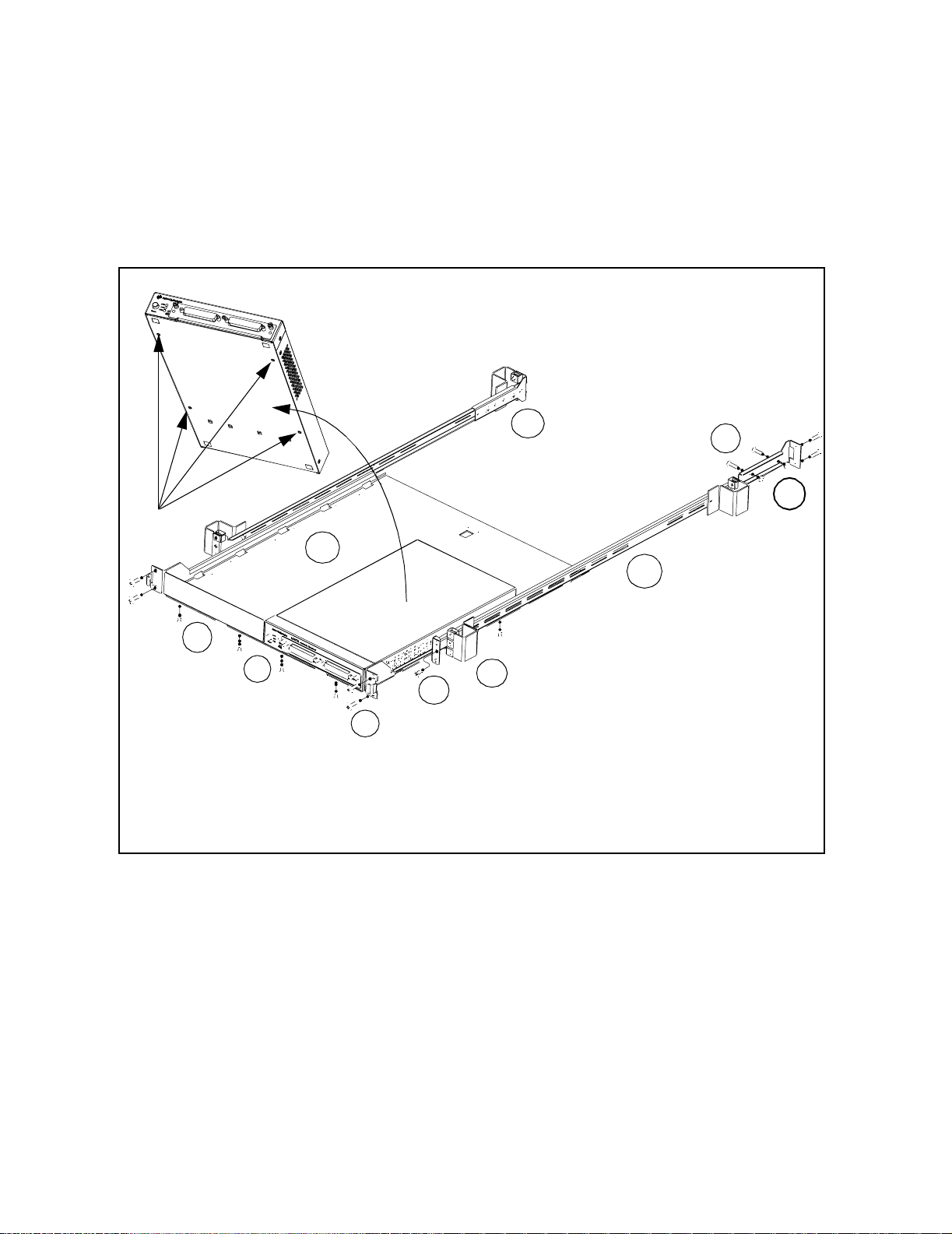
Procedure
Figure 1- 1 is a composite drawing of the Y1160A sliding shelf rack mount kit.
The drawing shows the location/usage of the hardware items listed in Table
1- 2.
10
7
8
9
1
4
2
5
3
6
Figure 1-1. Y1160A Instrument Rack Mount Kit (L4400 Series).
6 L4400 User’s Guide
Page 17
Introduction to the L4400 Series LXI Instruments 1
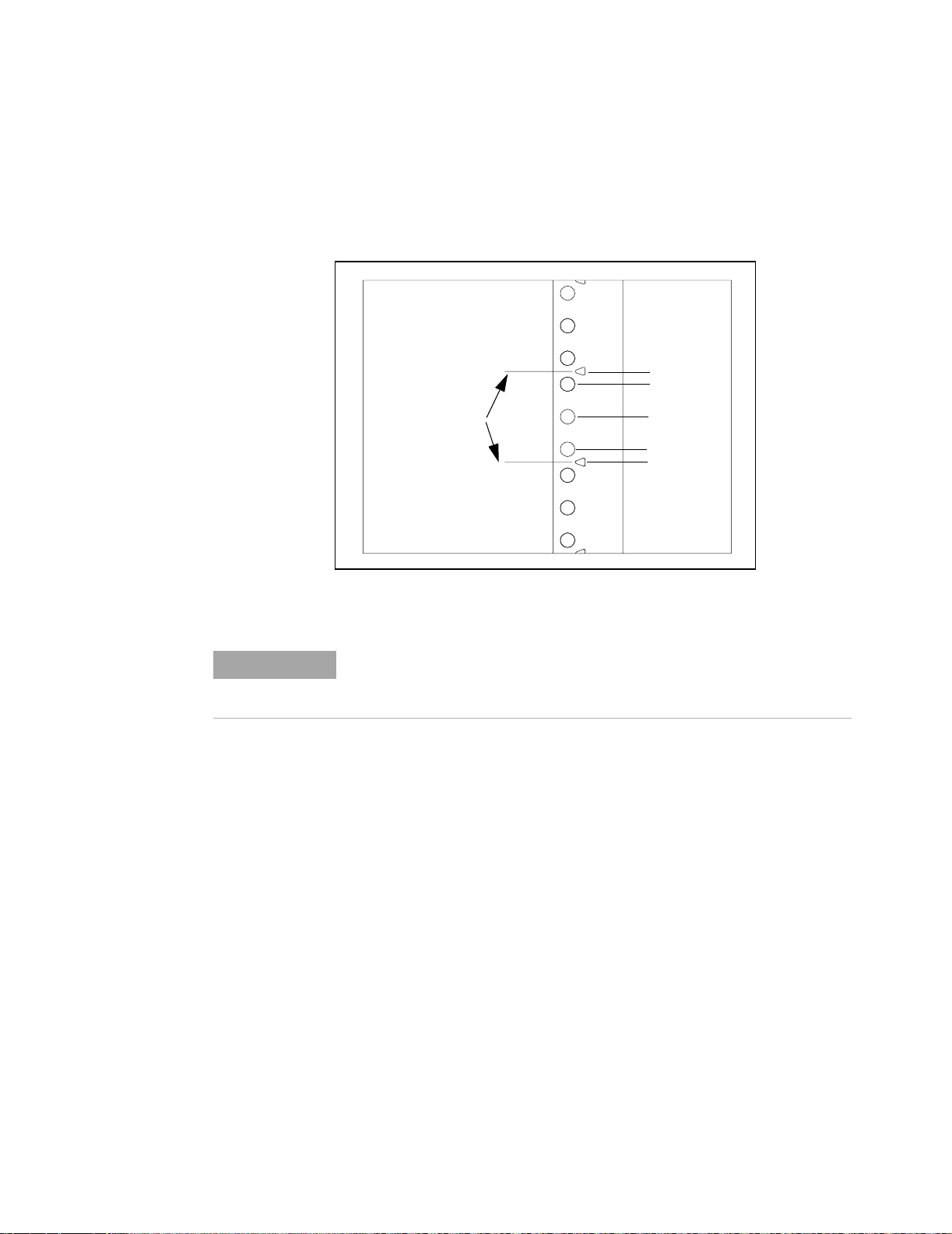
The L4400 instrument(s) can be mounted between any two adjacent EIA unit
indicators (Figure 1- 2). On Agilent racks, an EIA unit indicator is
represented by a triangle (
!) on the rack’s front and rear- facing columns. A
single EIA unit extends from the triangle indicator to the next indicator on
the column (1 Unit = 44.45 mm = 1.75 in).
EIA unit indicators
(1 EIA unit)
44.45 mm
(1.75 in)
6.35 mm
15.875 mm
15.875 mm
6.35 mm
Figure 1-2. EIA Unit Indicators for Installing the Y1160A Rack Mount Kit.
NOTE
It is not necessary to remove the cabinet side panels to rack mount the
L4400 instruments. The side panels can be removed, however, if additional
access to the cabinet’s vertical columns is desired.
Install the Shelf Rails
1. Select the vertical position in the rack between any two adjacent EIA unit
indicators where the L4400 instrument is to be installed. Insert clip- on nuts
(item 5) on the three holes between the unit indicators. Place nuts on both
the left and right front- facing columns (Figure 1- 3).
L4400 User’s Guide 7
Page 18
1 Introduction to the L4400 Series LXI Instruments
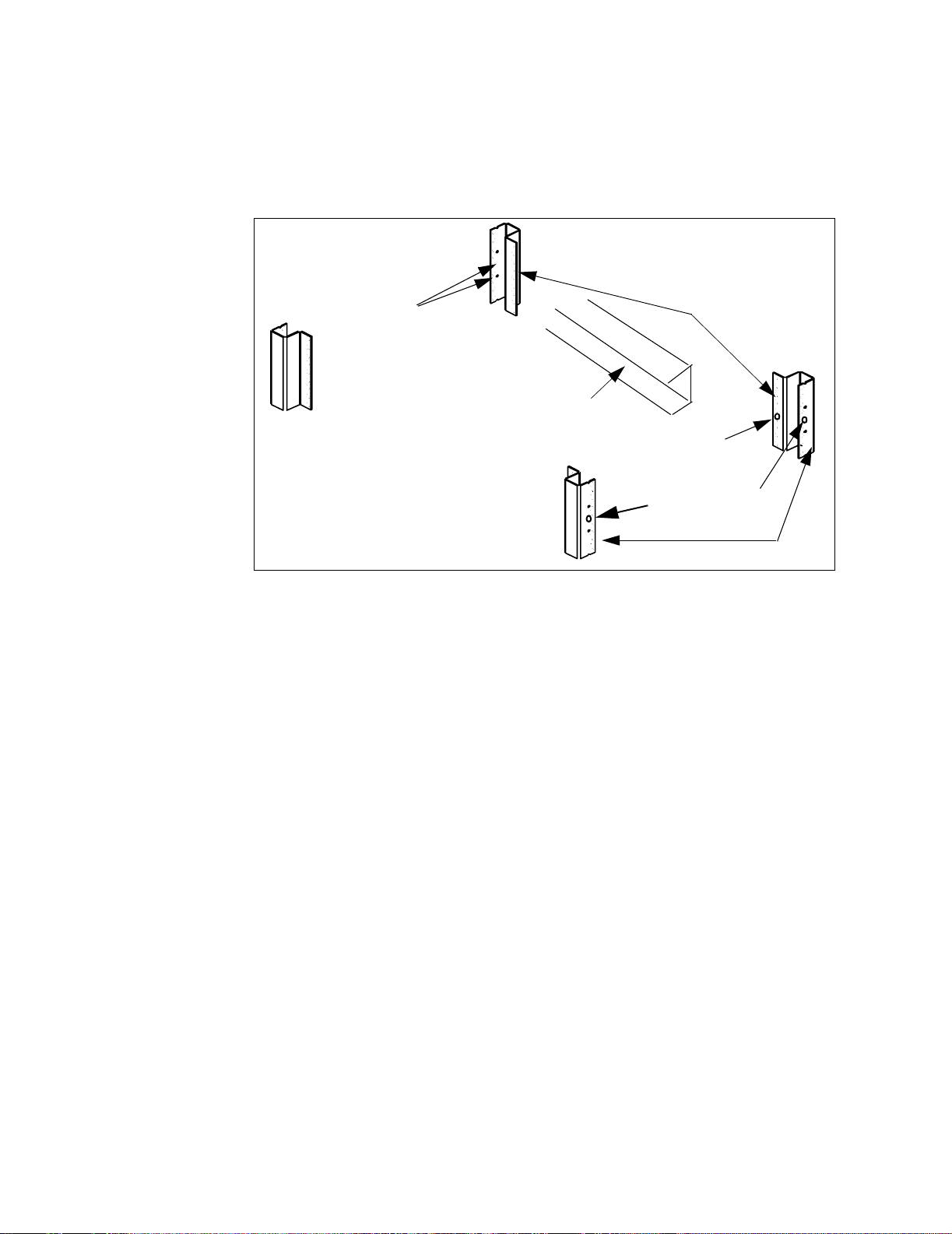
If center- facing columns with holes are present on the frame, insert a clip- on
nut on the hole perpendicular to the center hole on the front facing column.
See Figure 1-3.
back of rack
insert clip nuts
on first and third
holes between indicators
center-facing colums
(center of rack)
rail “channel
insert clip nut
if column present
insert clip nuts
between rack unit
indicators
front-facing colums
Figure 1-3. Rack Column and Shelf Rail Orientation.
2. With the rail “channel” facing the center of the rack, connect the rail to the
front facing column using a 10- 32 flathead screw (item 4) and the center
clip- on nut on the front-facing column. Repeat for the rail on the opposite
column. Ensure the rail channel faces the center of the rack.
If the rack has center- facing columns (Figure 1-3), insert a 10- 32 pan head
screw through the rail opening and clip nut (perpendicular to the
front- facing column). Repeat for the rail on the opposite column.
3. On the rack’s rear- facing columns, insert clip- on nuts on t he first and third
holes between the EIA unit indicators that are at the same vertical position
as the indicators on the front- facing columns.
4. Attach the rear brackets to the rail ends using two 10-32 pan head screws
(item 3) and two 10-32 nuts with lockwashers (item 6) per rail. Adjust the
bracket along the rail until the bracket end aligns with (covers) the rack’s
rear- facing columns. Tighten the 10- 32 pan head screws to firmly connect the
bracket to the rail and maintain the rail length.
Connect the rail brackets to the rear- facing columns using two 10- 32 pan
head screws per column.
8 L4400 User’s Guide
Page 19

Introduction to the L4400 Series LXI Instruments 1
Install the Sliding Shelf
Facing the rack, slide the shelf (item 7) onto the bottom surfaces of the rail
channels. The tabs at the back of the shelf pass underneath the channel
surface. The tabs allow you to extend the shelf from the cabinet, thus
providing a working surface for mounting the instruments.
Rail channel
Shelf tab
Bottom surface
Figure 1-4. Installing the Shelf.
Install Instruments on the Shelf
The L4400 instruments can be installed flush (even) with front edge of the
shelf, recessed in 50 mm increments, or reverse-mounted with the front of
the instrument facing the back of the rack cabinet.
1. Extend the shelf from the rack such that approximately 50% - 75% of the
shelf surface is outside of the rack. (The tabs on the back of the shelf that run
underneath the rail channel prevent the shelf from tipping.)
2. Determine the position of the instruments (flush, recessed, reversed). To
accommodate the terminal blocks (available with some of the L4400
instruments) and to simplify cable routing, it is recommended that the
instruments be mounted flush (even) with the front or back edge of the shelf.
3. Note the location of the four mounting holes on the bottom of the
instrument (Figure 1- 1). Set the carrier on the shelf, and align the mounting
holes with the holes on the shelf. Insert four M4x8 flat head screws (item 1)
upward through the bottom of the shelf and into the carrier mounting holes.
L4400 User’s Guide 9
Page 20
1 Introduction to the L4400 Series LXI Instruments
4. Install the second L4400 instrument (if present) in the shelf area adjacent
to the first instrument. If only one instrument is installed, install a filler
panel on the front edge of the unused area. Insert two M4x8 flat head screws
(item 1) upward through the bottom of the shelf and into the panel.
5. Connect the instrument power cord, LAN cable, and GPIB cable if present.
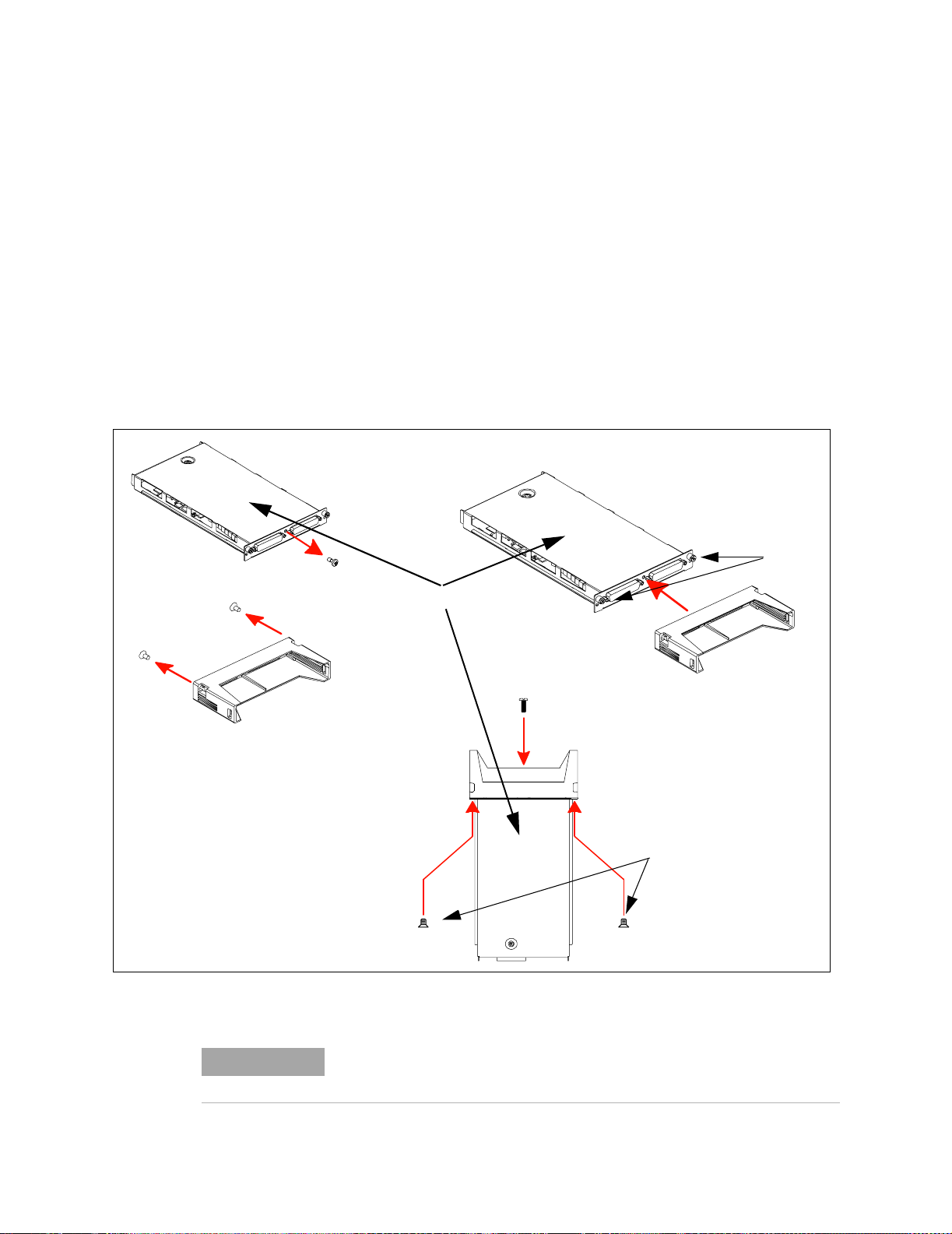
6. For instruments that have accompanying terminal blocks, partially remove
the instrument sub- assembly from the instrument (carrier) by loosening the
spring- loaded mounting screws (Figure 1- 5). Remove the support sleeve from
the terminal block. Locate and remove the flat head screws from the sleeve
and remove the pan head screw from between the instrument’s D- sub
connectors (Figure 1- 5). Connect the sleeve to the instrument using the flat
head and pan head screws as shown. Reconnect the sub- assembly.
spring-loaded
mounting screws
pan head screw
flat head screws
instrument sub-assembly
terminal block
support sleeve
pan head screw
flat head screws
Figure 1-5. Connecting the Terminal Block Support Sleeve.
NOTE
10 L4400 User’s Guide
Refer to Chapters 4-10 for information on Terminal Block wiring and
connecting the terminal block to the instrument.
Page 21

Applying Power
Introduction to the L4400 Series LXI Instruments 1
Connect the Shelf to the Rack Frame
Once the instruments are installed and all power cords and cables are routed
as intended, slide the shelf into the cabinet until the shelf handles meet the
front-facing columns of the rack frame. Using two10-32 pan head dress
screws (item 2) per column, secure the shelf to the frame.
The input power, operating environment, and storage environment
specifications for the L4400 series instruments are listed in Table 1-3. Refer
to the instrument data sheets for a complete listing of instrument
specifications. The data sheets can be found on the Web at:
www.agilent.com/find/L4400
Table 1-3. Agilent L4400 Series Instrument Input Power Specifications.
Instrument Description
L4421A
L4433A
L4437A
L4445A
L4450A
L4451A
L4452A
Power Supply:
Power Line Frequency:
Power Consumption: 50VA
Operating Environment:
Storage Environment:
Universal 100V to 240V
50Hz to 60Hz
Full accuracy for 0
Full accuracy to 80% R.H. at 40
-40
°C to 70°C
±10% auto sensing
Connecting the Power Cord and Turning On the Instrument
Connect the power cord supplied with the instrument or a power cord rated
for the conditions listed in Table 1-3 to the electrical outlet and to the
instrument.
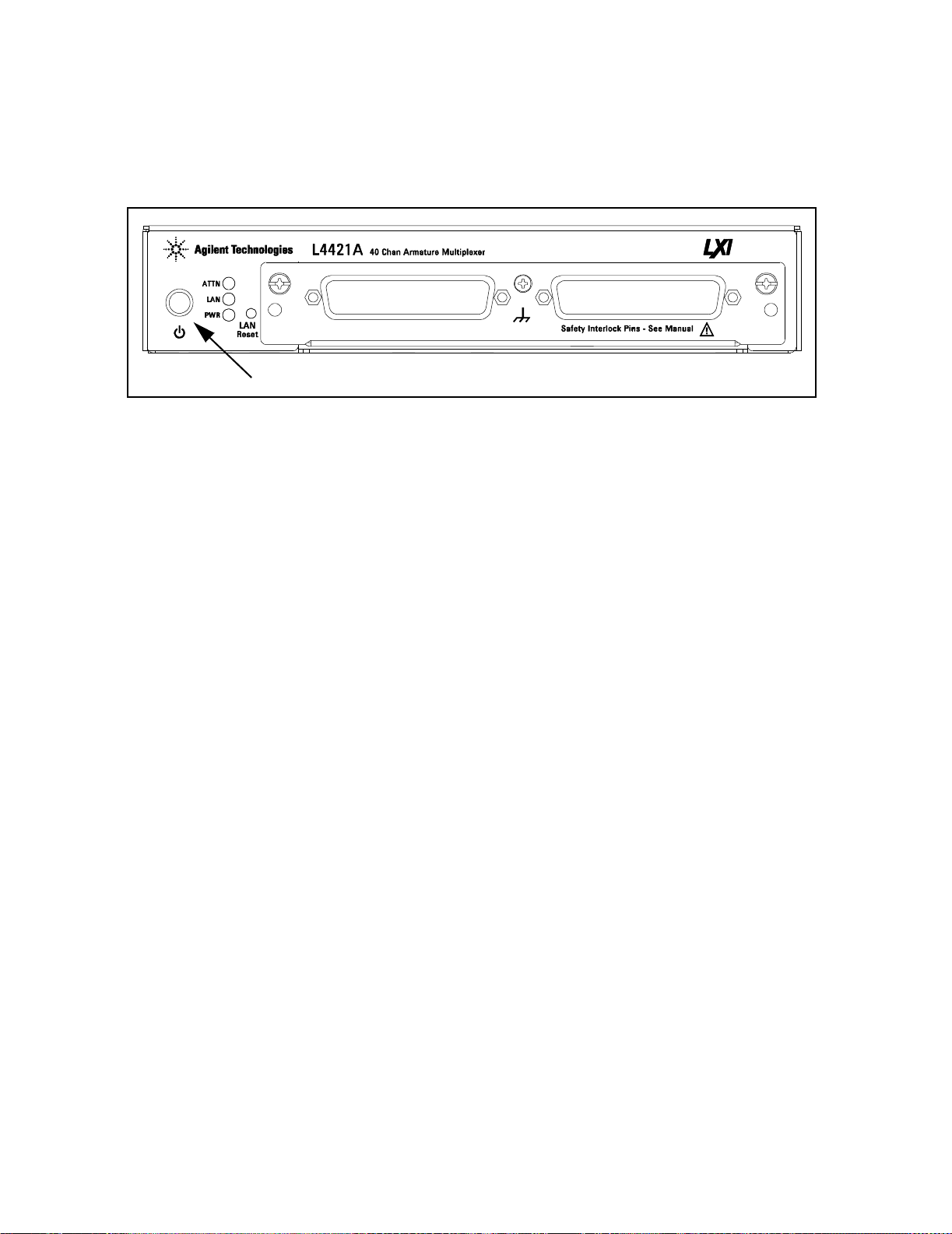
Turn the instrument on (and off) by pressing the power button shown in
Figure 1-6.
±10%
°C to 55°C
°C
L4400 User’s Guide 11
Page 22
1 Introduction to the L4400 Series LXI Instruments
Refer to Table 3- 1 (Chapter 3) for definitions of the LEDs (ATTN, LAN, PWR)
on the L4400 instrument front panel.
Power Button
Figure 1-6. Location of the L4400 Series Instrument Power Button.
12 L4400 User’s Guide
Page 23

Agilent L4400 LXI Class C Instruments
User’s Guide
2
Software Installation and Configuration
Installing the Agilent IO Libraries and L4400 Instrument Drivers 14
Configuring the L4400 Instruments 17
GPIB Configuration 33
Firmware Updates 39
Instrument Power-On and Default LAN Configuration States 45
This chapter contains the software installation and configuration procedures
required for you to use the L4400 series instruments. Also included are
procedures for configuring the LAN and (optional) GPIB interfaces, and for
testing the communication (IO) paths to the instruments.
Agilent Technologies
13
Page 24

2 Software Installation and Configuration
Installing the Agilent IO Libraries and L4400 Instrument Drivers
Communication and control of the L4400 series instruments from a Microsoft®
programming environment is provided through the following software that is
included with the L4400A instruments:
• Agilent E2094A IO Libraries Suite 14.1
• Agilent L4400A Product Reference CD- ROM (p/n 34989-13601)
This section covers the sequence and procedures for installing the IO libraries
and instrument drivers required to program the instruments.
Installing the Agilent IO Libraries
The Agilent IO Libraries Suite must be installed first, followed by the L4400
instrument drivers that are located on the Product Reference CD-ROM (p/n
34989-13601). The IO Libraries are contained on the Agilent Automation- Ready CD included with the instrument, or may be downloaded from the
Agilent Developer Network website at http://adn.tm.agilent.com, under ‘Software Downloads: IO Libraries Suite’.
Before installing the IO libraries, review table 2- 1 to verify that your computer
meets the specifications required by the software.
Table 2-1. Agilent IO Libraries Suite System Requirements.
Processor 450 MHz Intel Pentium® II or higher
Operating System Windows XP Professional or Home Edition (Service Pack 1 or
later
Windows 2000 Professional (Service Pack 4 or later)
Web Browser Microsoft Internet Explorer 5.01 or greater (recommended)
Available Memory 128 MB (256 MB or greater recommended)
Available Disk Space 225 MB required for installation:
- 160 MB for Microsoft .NET Framework
- 65 MB for Agilent IO Libraries Suite
175 MB required for operation:
- 110 MB for Microsoft .NET Framework
- 65 MB for Agilent IO Libraries Suite
Video Super VGA (800x600) with 256 colors
14 L4400 User’s Guide
Page 25
Software Installation and Configuration 2
Close all applications on your computer. Insert the Agilent Automation-Ready CD into
the CD-ROM drive. Follow the instructions as prompted during the installation. Accept
all default directories specified.
If the IO libraries installation does not start automatically, select Start > Run from the
Windows Start menu and type <drive>:\autorun\auto.exe where <drive> is the designator of the CD-ROM drive.
NOTE
NOTE
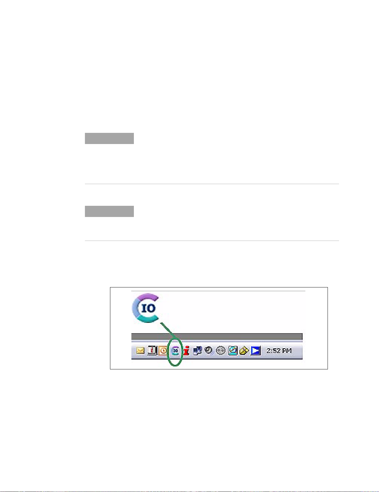
After the IO libraries have been successfully installed, you will see the Agilent IO Control (IO icon) in the taskbar notification area of your computer screen (Figure 2-1).
If another vendor’s implementation of VISA (Virtual Instrument Software
Architecture) is currently installed on your computer, continue installation
of the Agilent IO Libraries by installing Agilent VISA in side-by-side mode.
More information on side-by-side operation can be found in the Agilent IO
Libraries Suite Help (available after installation is complete) under “Using
Agilent VISA with Another Vendor’s VISA.
Installing the Agilent IO Libraries also installs the Interchangeable Virtual
Instrument (IVI) Shared Components. The IVI Shared Components are
required before IVI drivers (e.g. IVI-COM, IVI-C) can be installed (see
“Installing the L4400 Instrument Drivers”).
Figure 2-1. Agilent IO Control Icon.
Installing the L4400 Instrument Drivers
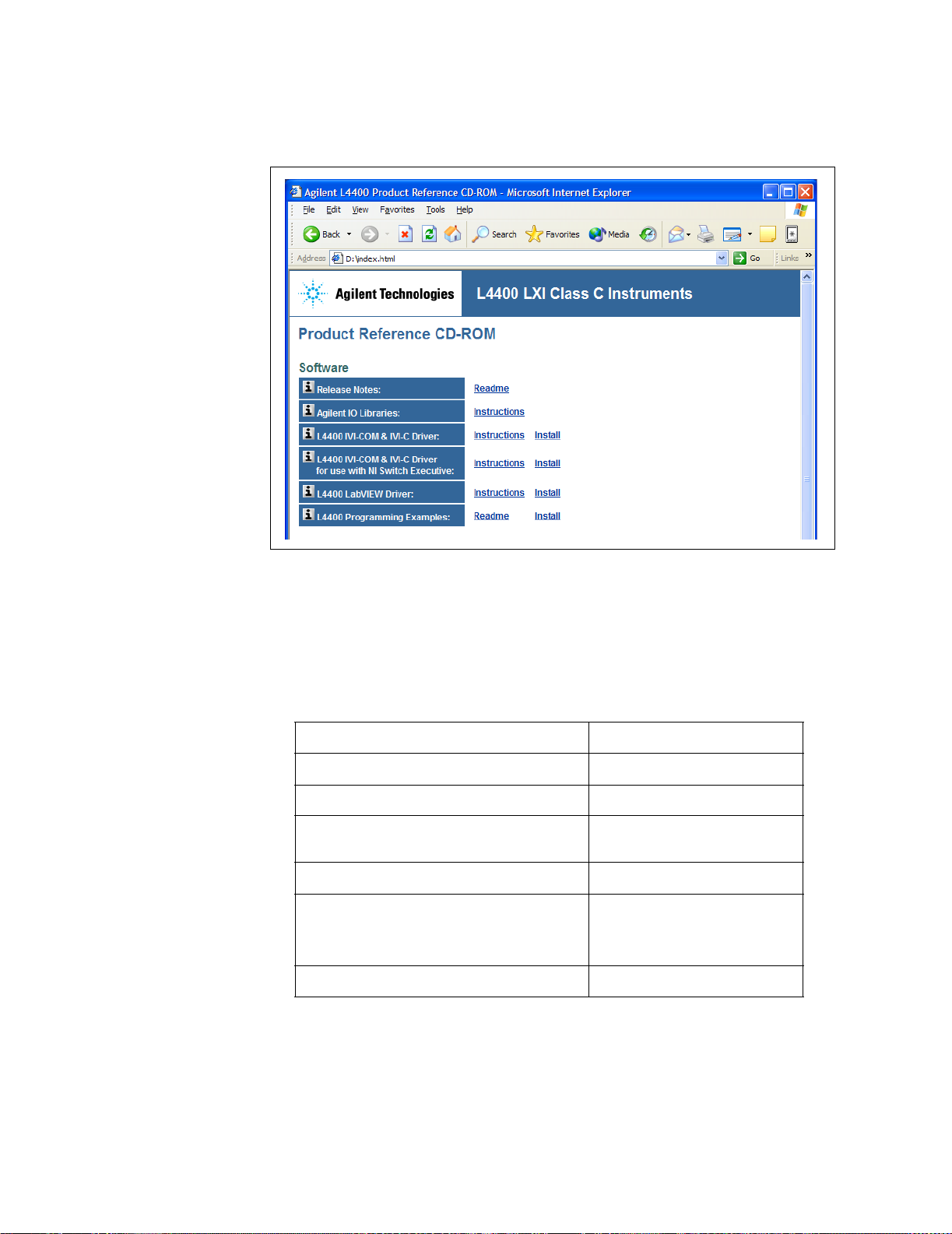
Insert the L4400 Product Reference CD-ROM into the computer. The installation program will open the menu window shown in Figure 2-2. If the program does not start
automatically, select Start -> Run -> Open: <cd-rom drive>:\index.html.
L4400 User’s Guide 15
Page 26
2 Software Installation and Configuration
Figure 2-2. L4400 Product Reference CD-ROM Software (Driver) Menu
Install the appropriate driver from the menu based on the environment you will use to
program the L4400 instruments. Table 2-2 contains a list of common environments and
corresponding drivers. Accept all default directories specified during installation.
Table 2-2. L4400 Programming Environments and Recommended Drivers
Programming Environment
Microsoft® Visual C 6.0 Visual C++, ANSI C
Microsoft® Visual Basic 6.0
Microsoft Visual Studio .NET for C#, C,
Visual Basic
Agilent VEE
National Instruments LabVIEW
National Instruments LabWindows/CVI
Recommended Drivers
IVI-C, IVI COM, VISA
IVI-COM, VISA, VISA-COM
IVI-COM
IVI-COM
LabVIEW Plug&Play (with
L44XX native mode driver),
IVI-C
IVI-C
For information on firmware updates that may be available after purchase,
refer to “Firmware Updates” at the end of this chapter.
16 L4400 User’s Guide
Page 27

Configuring the L4400 Instruments
Instrument configuration as applied to the L4400 series of LXI instruments
involves the following:
• identifying the IP address and host name (LAN programming)
• (optional) setting the GPIB address
• testing the communication paths (LAN and/or GPIB) to the instrument
• opening the Web interface to the instrument
Each task listed above is accomplished using the Agilent Connection Expert
Feature of the Agilent IO Libraries Suite.
The information included this section of the chapter is:
Software Installation and Configuration 2
• Selecting a LAN Network
• Connecting the LAN Cables
• Configuring the LAN Interface
• GPIB Configuration
Selecting a LAN Network
This user’s guide defines a private (isolated) LAN as a network in which
instrument access is limited to a direct connection between the computer and
the instrument, or to multiple instruments connected via a dedicated router or
switch. A site (company- wide) LAN is defined as a network in which
instrument access is available to many users in on-site and remote locations.
The instrument’s application and/or your company’s Information Technology
(IT) department may have guidelines that help decide the type (private or site)
of network used. If a network configuration has not been determined, refer to
the following considerations concerning each type.
Private LAN Considerations
Some of the basic parameters of a private LAN network to consider are:
security, performance, reliability, and IP address availability.
L4400 User’s Guide 17
Page 28

2 Software Installation and Configuration
Security: a private network generally involves direct connections between the
computer and the instruments, and may include switches and routers. Access
to the instrument is limited to users connected directly to the private network,
as opposed to users on a site network that could locate and access the
instrument from any location - possibly disrupting tests in progress. Code
generation for test systems on a private network is often simplified as
protection against unauthorized users may not be required.
Performance: test systems where large amounts of data are transferred
usually have faster throughput on a private network. On a site network, heavy
and unpredictable LAN traffic (lots of data) affects each instrument (node) on
the network. The impact on a test system is that repeatability is difficult to
achieve as latencies are difficult to account for.
Reliability: private networks are fundamentally more reliable than site
networks as they host fewer users and are less complex than site networks.
Private networks are isolated from conditions that could bring down (crash) a
site network.
IP Address Availability: Every instrument (node) on a LAN (private or site)
has an IP (Internet Protocol) address. Due to the expanding use of the internet,
the number of site network IP addresses available is limited. By using a router
with Dynamic Host Configuration Protocol (DHCP) capability on a private
network, the router can assign an IP address to each instrument thus creating
a sub- network (subnet) that does not consume site IP addresses.
Site LAN Considerations
For applications requiring access by many users or by users at distributed
sites, a site LAN network is required. In addition to supporting multiple users,
site LANs often offer the advantage of being maintained by IT departments.
When using a site LAN, consult your IT department regarding all LAN
configuration and security issues.
Connecting the LAN Cables
LAN cables are connected to the LAN terminal on the instrument, the
computer, and to the router or switch if they are part of your network.
18 L4400 User’s Guide
Page 29
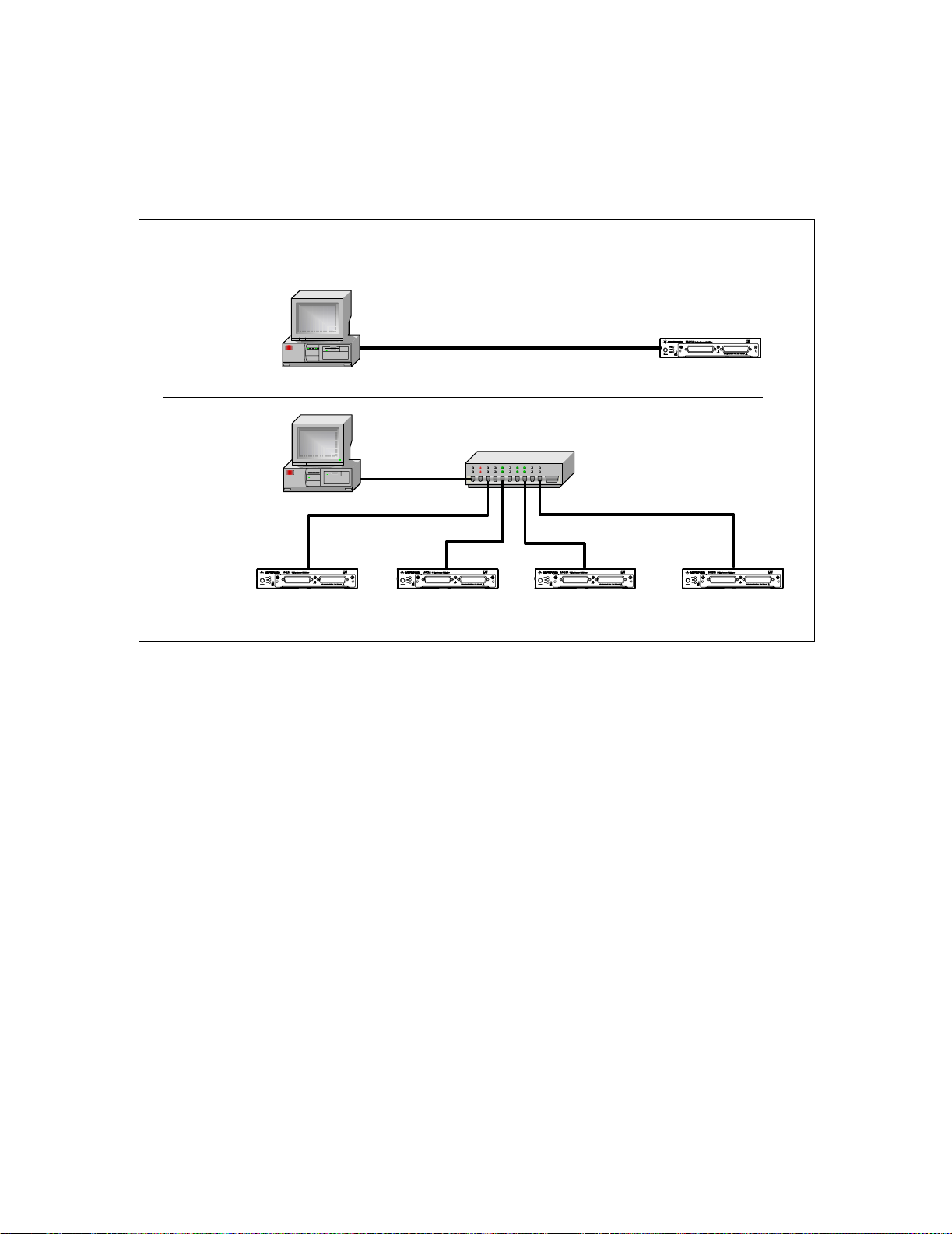
Private Network Connections
Figure 2-3 shows typical LAN cable connections for a private network.
Typical Private (isolated) LAN Networks
Direct
Connection
Software Installation and Configuration 2
Router / Switch
Connection
When making a direct connection between the L4400 instrument and the PC,
use the yellow LAN crossover cable provided with the instrument. Note, if
your computer supports Auto-MDIX or contains a LAN card with gigabit data
transfer rates, the (yellow) crossover cable is not required. A standard LAN
cable can be used instead. For private LAN networks that include a switch or
router, use standard LAN cables for network connections. Do not use the
crossover cable.
CAT5 Crossover Cable
PC
Ethernet Hub / Switch / Router
PC
L4400 L4400 L4400 L4400
L4400
Figure 2-3. Typical Private LAN Network Connections.
Once the LAN cables are connected, you can turn on the L4400 instrument(s).
L4400 User’s Guide 19
Page 30

2 Software Installation and Configuration
Site Network Connections
Figure 2-4 shows typical LAN cable connections for a site network.
Typical Site LAN Networks
To Site LAN
Router / Switch
Connection
On site networks, the L4400 instruments and the computer are connected
directly to site LAN ports, or are connected to the site LAN through a switch.
In each site network configuration, standard LAN cables are used.
Once all LAN cables are connected, turn on the L4400A instrument.
PC
Ethernet Hub / Switch / Router
PC
L4400 L4400
Figure 2-4. Typical Site LAN Network Connections.
standard LAN cable
L4400
L4400
To Site LAN
L4400
IP Addresses and Host Names
Dynamic Host Configuration Protocol (DHCP) and Automatic IP are enabled
on each L4400 series instrument shipped from Agilent. This allows the
instrument to automatically obtain an address on the network. If there is a
DHCP server on the network, the server will assign the address to the
instrument.
If there is not a DHCP server on the network, the L4400 instrument will
automatically determine an address to use. The address will be in the range of
169.254.xxx.xxx. If available, the instrument will try to acquire its default
setting of 169.254.44.88.
20 L4400 User’s Guide
Page 31

Software Installation and Configuration 2
Host Names Each L4400 instrument has a default host name. The format of
the host name is:
A- L44xxA-yyyyy
where ‘L44xxA’ is replaced by the module number (e.g. L4421A) and ‘yyyyy’
are the last five digits of the instrument serial number.
The instrument host name is reported by Agilent Connection Expert for
network servers that support Dynamic Domain Name Service (DNS). For
network servers that do not support Dynamic DNS, only the IP address is
reported.
Instrument Addressing
During programming, an L4400 series instrument is accessed through its
address string which consists of an IP address or host name. For example:
TCPIP0::192:168:1.221::inst0::INSTR
The L4400 series instruments can also be accessed using a host name as part
of the address string. For example:
TCPIP0::A-L4450A-12345.agilent.com::inst0::INSTR
NOTE
The L4400 instruments can be restored to their default configurations by
pressing the ‘Reset’ pin on the instrument’s front or rear panels.
Computer Configuration
Most computers used for instrument/system control are configured for LAN
and Internet access. Before starting Agilent Connection Expert to locate and
configure the instruments, verify that your computer is able to connect to the
network that will include the instruments.
A Web browser is used to open web interfaces to the L4400 instruments (See
“Using the Instrument Web Interface”). In some network configurations, a
proxy server cannot be used to access the instrument IP addresses. In these
situations, the browser must be set to disable the proxy for the instrument’s
address.
Configuring the LAN Interface
With the L4400 instrument(s) turned on and connected to a private or site
LAN network, start Agilent Connection Expert utility by clicking on the
Agilent IO Control icon and selecting “Agilent Connection Expert from the
pop- up menu (Figure 2- 5).
L4400 User’s Guide 21
Page 32

2 Software Installation and Configuration
NOTE
The procedure for using Agilent Connection Expert to locate and configure
L4400 instruments is independent of the type of network you are using
(private or site) and the network devices present (switches or routers).
For more information on Interactive IO, refer to the Agilent IO Libraries
Suite Getting Started Guide. The guide is available on-line by clicking on
the Agilent IO Control icon and then selecting Documentation
Libraries Suite Getting Started.
Clicking the icon opens the
pop-up menu
!IO
Figure 2-5. Starting Agilent Connection Expert.
Locating the Instruments
Agilent Connection Expert opens with a “welcome screen” and window similar
to that shown in Figure 2- 6. The computer interfaces configured during
installation of the Agilent IO Libraries are displayed in the left column
(Explorer pane) and the properties of the configured interface and instrument
are displayed in the right column (Properties pane).
22 L4400 User’s Guide
Page 33

Explorer pane
Properties pane
Software Installation and Configuration 2
Figure 2-6. Agilent Connection Expert (ACE) Opening Window.
To search the network for instruments, click on “Add Instrument” located on
the Connection Expert tool bar. From the “Add Instrument” window, select the
LAN (TCPIP0) interface and click on ‘OK’. See Figure 2-7.
Figure 2-7. Agilent Connection Expert “Add Instrument Window”.
L4400 User’s Guide 23
Page 34

2 Software Installation and Configuration
Clicking on “Find Instruments” (Figure 2- 8) opens the search window. Clicking
on “Find Now” performs the search for instruments on the LAN network.
Instruments found (discovered) on the network (local subnet) are indicated as
shown. In the Figure 2-8 example, two instruments were located on the router
subnet.
Figure 2-8. L4400 Instrument Private LAN Connection.
NOTE
The “Find Instrument” function of Agilent Connection Expert is supported
only on computers that have a single LAN card installed. If your computer
has more than one LAN card, the L4400 instruments must be entered
“manually” using the IP addresses.
Adding and Configuring the Instruments
To add an instrument to the network configuration, select (highlight) the
instrument host name/IP address and click on ‘OK’ in the “Search for Instruments on the LAN” window. This opens the “LAN Instrument” window shown
in Figure 2- 9.
24 L4400 User’s Guide
Page 35

Software Installation and Configuration 2
Click either to
test connection
Figure 2-9. Verifying a Communication Path to the Instrument.
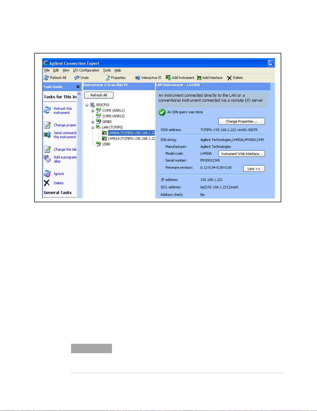
The LAN Instrument window identifies the instrument’s host name, its IP
address, its VISA address, and product number. Because the network server
used in this example does not support Dynamic DNS, the host name is not registered for use by the server. Thus, the instrument is accessed by its IP
address.
Note serial number to identify
multiple instruments
Click on “Test Connection” or “Identify Instrument” to test the communication
path to the instrument. Click on”OK” to add the configured instrument to your
network.
Repeat the sequence of Figures 2- 7 through 2-9 for each instrument. As instruments are added, they appear in the Agilent Connection Expert Explorer pane
as shown in Figure 2- 10. Selecting the instrument in the Explorer pane displays its properties in the Properties pane.
L4400 User’s Guide 25
Page 36
2 Software Installation and Configuration
Figure 2-10. Configured Instruments added to LAN Network.
Interactive IO
The Interactive IO feature of Agilent Connection Expert allows you to interact
with the instruments by sending commands and seeing the instruments’
responses. Interactive IO can help you:
• troubleshoot communication problems
• learn the instrument's command set
• prototype commands and check the instrument's responses before writing
code
With Interactive IO, you can choose from a menu of common commands
(*IDN?, *RST, *TST?), or execute commands from the instrument’s command
set (see Chapters 4-10 for the commands available with each instrument).
Figure 2- 11 shows how Interactive IO is started from Agilent Connection
Expert.
NOTE
For more information on Interactive IO, refer to the Agilent IO Libraries
Suite Getting Started Guide. The guide is available on-line by clicking on
the Agilent IO Control icon and then selecting Documentation !IO
Libraries Suite Getting Started.
26 L4400 User’s Guide
Page 37
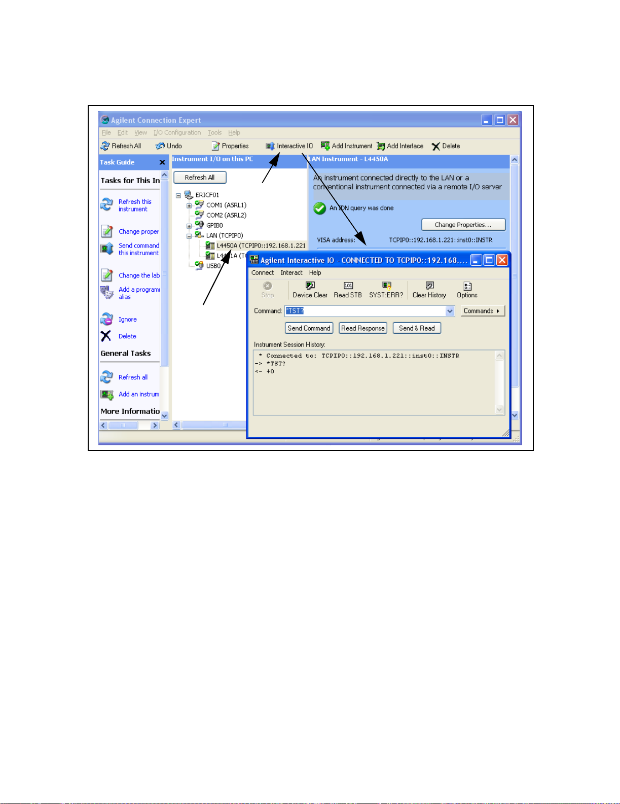
Select Interactive IO
Select (highlight) instrument
Software Installation and Configuration 2
Figure 2-11. Selecting an Instrument and Starting Interactive IO.
Identifying the Instruments
L4400 series instruments are comprised of the carrier, the instrument
sub- assembly, and on selected instruments, a wiring terminal block. The
carrier and instrument sub- assembly have separate serial numbers and
separate firmware revisions. The commands used to query these parameters
are:
• *IDN? (returns the carrier serial number and firmware revision)
• SYSTem:CTYPe? 1 (returns the instrument sub- assembly serial
number and firmware revision)
• SYSTem:CDEScription? 1 (returns the instrument description.)
These commands can be executed from the Interactive IO window. Examples
of the information returned by each command are as follows:
L4400 User’s Guide 27
Page 38

2 Software Installation and Configuration
*IDN?
Agilent Technologies, L4421A, MY00012345, 0.12-0.04-0.00-0.00
product
carrier serial number
SYST:CTYP? 1
Agilent Technologies,L4421A, MY44000237, 2.16
product
sub-assembly serial number
SYST:DESC? 1
“64-bit Digital I/O Module with Memory and Counter”
Using the Instrument Web Interface
Each L4400 series instrument can be programmed using its Web- based
interface. The Web interface functions as a virtual front panel which can also
be used for:
• interactive control
• familiarization with instrument capabilities
• determining / changing instrument configuration
• troubleshooting and debugging
carrier firmware revision
sub-assembly firmware revision
Comprehensive on- line help providing Web interface usage information is
available with each Web window.
The instrument Web interface can be opened from Agilent Connection Expert
as shown in Figure 2- 12. The Web interface can also be opened directly from a
Web browser by entering the instrument’s IP address or host name in the
browser’s ‘Address’ window.
28 L4400 User’s Guide
Page 39

Select the instrument /
open the Web interface
Software Installation and Configuration 2
Figure 2-12. Opening the Instrument Web Interface.
L4400 User’s Guide 29
Page 40

2 Software Installation and Configuration
An example of the Web interface window is shown in Figure 2-13.
Figure 2-13. L4450A Web Interface (Welcome Page).
NOTE
Instruments on the network can be physically identified by selecting
Turn on Front Panel Identification Indicator within the Web interface.
This causes the instrument’s front panel LAN LED to flash continually until
Turn off Front Panel Identification Indicator is selected.
Editing the Instrument’s LAN Settings
Once a communication path to the instrument has been opened, the
instrument’s LAN configuration can be viewed and modified using the Web
interface.
30 L4400 User’s Guide
Page 41

Software Installation and Configuration 2
On the Web “welcome page”, click ‘View and Modify Configuration’. This opens
the configuration window shown in Figure 2- 14.
Figure 2-14. Viewing LAN Configuration Settings from the Web Interface.
L4400 User’s Guide 31
Page 42

2 Software Installation and Configuration
Clicking ‘Modify Configuration’ opens the window shown in Figure 2- 15 which
allows you to edit the parameters shown.
Figure 2-15. Changing the Instrument LAN Interface Configuration.
NOTE
Selecting “Help with this Page” on any Web interface window provides
information on the use of the current Web interface page. Selecting “Help
with this Page”on the “Browser Web Control” page provides a listing of
the help contents.
LAN Configuration Command Summary
In addition to using the Web interface, the instrument’s LAN configuration can
be set/changed changed programmatically. Chapter 3, Table 3- 3 provides a
listing of the LAN configuration commands implemented by the L4400 series
instruments.
Refer to the L4400 Programmers Reference on the Product Reference CD- ROM
(p/n 34989-13601) for detailed information on the commands.
32 L4400 User’s Guide
Page 43

GPIB Configuration
Software Installation and Configuration 2
NOTE
The L4400 series instruments are available with an optional GPIB interface.
The steps required to configure L4400 instruments for use over GPIB include:
• connecting the GPIB cables
• adding the instrument to the GPIB interface configuration (using Agilent
Connection Expert)
• changing the instrument GPIB address (systems with multiple L4400
instruments)
• testing the IO path
Each L4400 series instrument is shipped from the factory with a default GPIB
address of 9. Because instruments on the GPIB bus must have unique
addresses, the L4400 instruments must be turned on one at a time, and the
GPIB address changed before the next instrument is turned on and added to
the configuration.
The following information assumes the GPIB interface card has been
installed in your computer. If necessary, install the card as instructed by
the documentation provided with the card.
Connecting the GPIB Cables
GPIB cables can be connected in a “star” (all cables connect directly to the
computer) or “linear” (instrument to instrument) configuration.
For systems with multiple L4400 series instruments, turn on only one L4400
instrument at this time. If there is another instrument on the bus at GPIB
address 9 (i.e. 34980A), turn off that instrument until the address of the
current L4400 instrument is changed.
Starting Agilent Connection Expert
Start Agilent Connection Expert by clicking the Agilent Control icon and
selecting “Agilent Connection Expert” from the pop- up menu (Figure 2- 5).
The computer interfaces configured during installation of the Agilent IO
libraries are displayed in the left column (Explorer pane) including the GPIB
interface if a GPIB card is installed in your computer.
L4400 User’s Guide 33
Page 44
2 Software Installation and Configuration
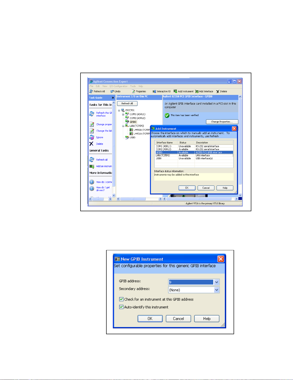
Adding Instruments to the GPIB Configuration
Highlight the GPIB interface (GPIB0) and select “Add Instrument” on the tool
bar. Select the GPIB interface in the “Add Instrument” window and click ‘OK’.
Figure 2-16. Adding Instruments to the GPIB Interface.
In the ‘configurable properties’ window shown in Figure 2-17, select GPIB
address 9 and click ‘OK’. This is the factory default address that will be
changed as necessary in the following steps.
Figure 2-17. Specifying the GPIB Address when Adding an Instrument.
34 L4400 User’s Guide
Page 45
Software Installation and Configuration 2
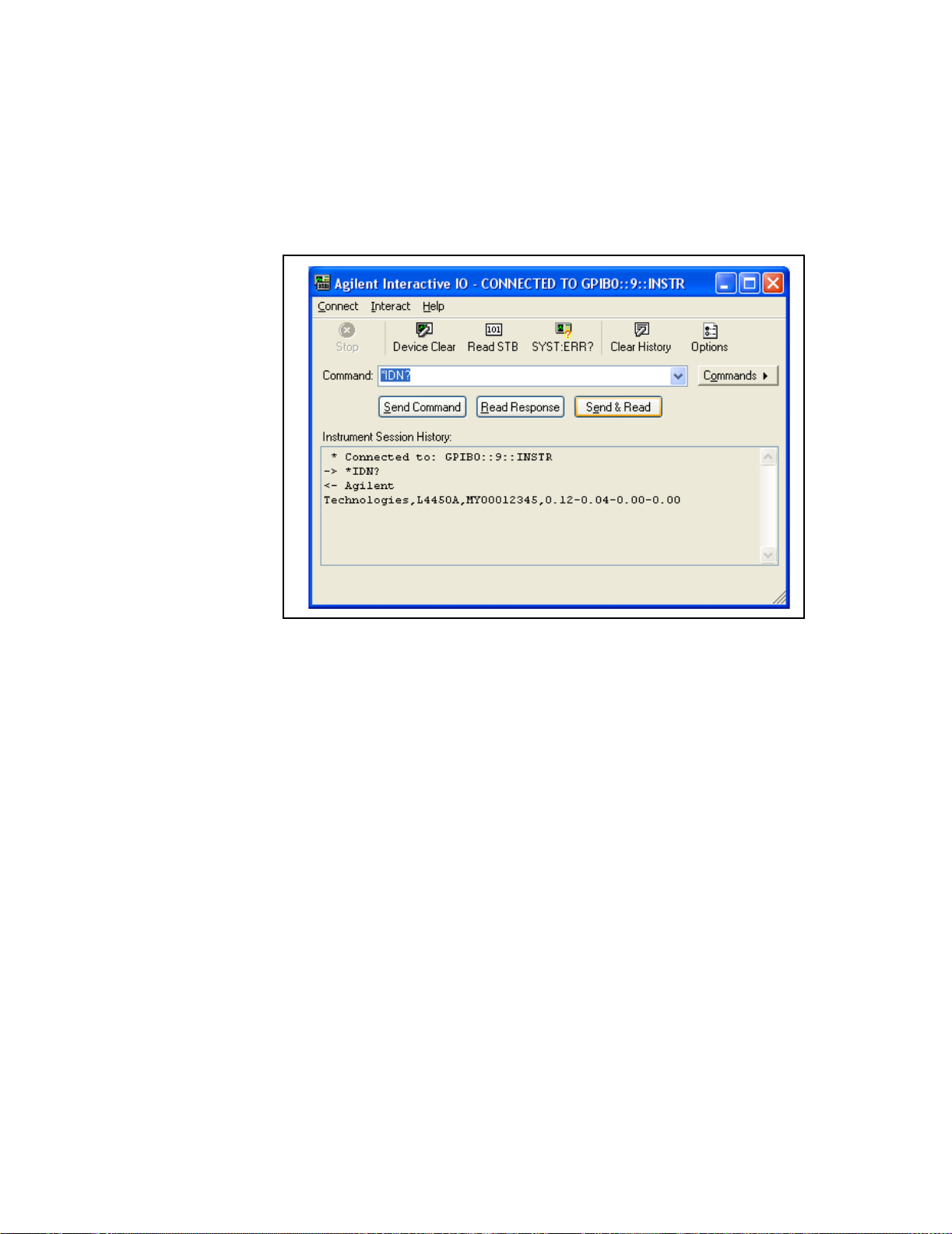
Verifying the GPIB Path
In the Agilent Connection Expert window, select and open ‘Interactive IO’.
Verify communication to the instrument by sending the *IDN? command using
Send & Read below the command line.
Figure 2-18. GPIB Communication Using the Default GPIB Address.
The GPIB Address String
When programming the L4400 instruments over GPIB, the instrument’s GPIB
address is included in the address string. For example:
GPIB0::9::INSTR
Changing the GPIB Address
If you have only one L4400 instrument on the GPIB interface and there are no other
instruments on the bus, the L4400 instrument address can remain set to 9. If you have
multiple L4400 instruments or there is another GPIB instrument at address 9, then one of
the addresses must be changed.
The command used to set the GPIB address on all L4400 instruments is:
SYSTem:COMMunication:GPIB:ADDRess < address >
The command can be abbreviated by including only the upper-case letters in the command syntax. The Interactive IO window is used to set the GPIB address as shown in
L4400 User’s Guide 35
Page 46

2 Software Installation and Configuration
Figure 2-19. In this example, the GPIB address is set to 10.
Figure 2-19. Setting the GPIB Address Using the Interactive IO Window.
Once the address is changed within the instrument, the address must also be
changed in the Agilent Connection Expert’s “configuration tables.”
36 L4400 User’s Guide
Page 47

Software Installation and Configuration 2
From the Agilent Connection Expert main window, highlight the instrument added and
then click ‘Change Properties ...”. Within the configurable properties window, change
the address of the instrument from ‘9’ to ‘10’ and click ‘OK’.
Highlight instrument and
select, change address to
‘10’.
Figure 2-20. Changing the GPIB Address within Configuration Expert.
Verifying the new GPIB Path
To verify the GPIB address change, you can close the Interactive IO window, select the
instrument, and reopen Interactive IO. Or, with Interactive IO remaining open, select
‘Connect’ and change the address from ‘9’ to ‘10’. Once connected to GPIB address
L4400 User’s Guide 37
Page 48

2 Software Installation and Configuration
‘10’, you can send the *IDN? command and verify the response from the instrument.
Figure 2-21. Connecting to GPIB Address 10 using Interactive IO.
Adding Additional Instruments
Additional instruments are added to the GPIB configuration using the process described
earlier. The steps are summarized as follows and assume the GPIB cable has been connected between the computer and the new instrument.
1. Turn on the “next” L4400 instrument. Do not turn on those instruments whose
addresses are still set to the default address of ‘9’.
2. Open the Agilent Configuration Expert “Add Instrument” window and select the
instrument’s GPIB address in the “configurable properties” window (Figures 2-16 and
2-17).
3. Open the Agilent Connection Expert “Interactive IO” window (Figure 2-18). Change
the instrument’s GPIB address using the command:
SYSTem:COMMunication:GPIB:ADDRess < address >
4. Change the address in the Agilent Connection Expert’s configuration table to the new
instrument address (Figure 2-20).
5. Verify the communication path to the new address.
38 L4400 User’s Guide
Page 49

Firmware Updates
Firmware updates for the L4400 series instruments consist of updates to the
instrument carrier firmware, and if necessary, an update of the instrument
module firmware. The updates are made available via the Web. The firmware
is installed using the Agilent L4400 Firmware Update Utility, also available on
the web. This section contains information for locating and downloading the
update utility and firmware to your computer, and then using the utility to
install the firmware.
Downloading the Update Utility and Firmware
Firmware updates (if available) for the L4400 series instruments can be found
on the Web at:
www.agilent.com/find/L4400
Software Installation and Configuration 2
Once this page is displayed, click on ‘Library’ under the heading “More
Details.” From the ‘Library’ window select:
√ L4400 Firmware Update Revision <revision number>
√ Documents & Downloads
√ Agilent L4400 Firmware Update Utility
Save the utility application to a directory (e.g. Temp) on your PC. Note the
directory location as you will need to install the utility from this location.
Installing the Firmware Update Utility
Downloading the firmware update utility copies the application to your PC but
does not install the utility. From the directory where the application was
saved, double- click the firmware update utility application (.exe file). For
example:
FirmwareUpdateUtility_B_01_09_V3.exe
This starts the application’s installation “wizard”. Follow the instructions as
prompted. This will create and install the utility in the directory:
C:\Program Files\Agilent\Firmware Update Utility
L4400 User’s Guide 39
Page 50

2 Software Installation and Configuration
Downloading and Installing the Instrument Firmware
Once the utility is saved, return to the Web page and click on:
Agilent Firmware Revision <revision number>
Save the firmware file to a directory on your PC (e.g. Temp). Note the directory
location as you will need to specify the path to the firmware file when you run
the firmware update utility.
When updating from the LAN interface, the update utility requires you to specify the instrument host name or IP address. Before running the utility, test the
communication path to the instrument(s) using Agilent Connection Expert.
Open Agilent Connection Expert and refresh the LAN and GPIB (if present)
interfaces by clicking ‘Refresh All’ (Figure 2- 10). A “
the instrument indicates communication with the instrument on that interface. Note the host names or IP addresses (assuming an update over the LAN
interface) of the instruments to receive firmware updates.
1. From the directory where the update utility was installed, start the utility by selecting
FirmwareUpdateUtility.exe.
√ ” in a green circle next to
40 L4400 User’s Guide
Page 51

Software Installation and Configuration 2
Click ‘Next’ until the window shown in Figure 2-22 appears.
Figure 2-22. Firmware Update Utility Firmware File Selection.
2. Using the ‘Browse’ button, specify the path to the firmware file and then
click ‘Next’.
NOTE
The ‘Applicable Model’ window lists the L4400 series instruments which
are updateable by the current firmware (.xs) image. The window is
NOTused to select the instrument receiving the firmware update.
Firmware updates are performed on one instrument at a time. Once the
firmware update is complete, you must exit and re-start the utility to
update each instrument.
L4400 User’s Guide 41
Page 52

2 Software Installation and Configuration
3. Select the I/O interface to be used to upgrade the instrument firmware and
then select ‘Next’ (Figure 2- 23).
Figure 2-23. Selecting the Instrument Interface.
4. If the LAN interface is selected (Figure 2-23), enter the instrument host
name or IP address and click ‘Update’. If the GPIB interface is used, select the
instrument’s GPIB address.
42 L4400 User’s Guide
Page 53

Software Installation and Configuration 2
The firmware update process takes several minutes. The instrument’s front
panel ATTN indicator will flash green while the update is in progress.
enter host name
or IP address
Figure 2-23. Entering the Instrument Host Name or IP Address.
When the update to the instrument carrier firmware is complete, the results
are indicated as shown in Figure 2- 24. Note that an update of the instrument
sub-assembly firmware may continue for a few moments after the update
results message appears.
NOTE
Instrument sub-assembly firmware updates are performed automatically if
the current sub-assembly firmware revision is incompatible with the
updated carrier firmware.
L4400 User’s Guide 43
Page 54

2 Software Installation and Configuration
Figure 2-24. Instrument Firmware Update Complete.
5. Once the carrier update AND instrument sub- assembly update (if one
occurs) complete and no instrument activity is indicated by the front panel
LEDs, cycle power on the instrument. Once the power-on sequence completes,
select ‘Refresh All’ in the Agilent Connection Expert (Figure 2- 10).
Agilent Connection Expert may report that the instrument’s configuration has
changed. This is represented by a yellow triangle and an exclamation point (!)
next to the updated instrument. Select (highlight) the instrument name. Select
‘Change Properties...’ and then click either ‘Test Connection’ or ‘Identify
Instrument’ to update Agilent Connection Expert and then click ‘OK’. Repeat
for each updated instrument on the LAN and GPIB interfaces.
44 L4400 User’s Guide
Page 55

Software Installation and Configuration 2
Instrument Power-On and Default LAN Configuration States
The L4400 series instruments covered in this user’s guide are set to their
power on and preset states using any one the following commands:
*RST
SYSTem:CPON 1
SYSTem:PRESet
Table 2-3 lists the power-on and preset states for each instrument.
Table 2-3. L4400 Instrument Power-on and Preset States
L4400 Series Instrument
L4421A 40-Channel Armature Multiplexer
L4433A Dual/Quad 4x8 Reed Matrix
L4437A 32-Channel Form A/ Form C
General Purpose Switch
L4445A Microwave Switch / Attenuator Driver
L4450A 64-Bit Digital I/O w/Memory and Counter
L4451A 4-Channel Isolated D/A Converter
w/Memory
L4452A Multifunction with Digital I/O, D/A,
Totalizer
LAN Reset (Default) Configuration
Power-on Preset States
All channels open
All channels open
2-wire/1-wire mode: no change
All channels open
Channel drives enabled = user-
defined defaults
I/O ports = Input
Count = 0
Trace memory = cleared
DACs = 0Vdc
Trace wavforms = cleared
DIO Ports = Input
Count = 0
DACs = 0Vdc
Pressing the “LAN Reset” button (recessed) on the L4400 instrument front or
rear panel restores the instrument’s default LAN configuration. Table 2- 4 lists
the default LAN configuration settings.
L4400 User’s Guide 45
Page 56

2 Software Installation and Configuration
Table 2-4. Default LAN Configuration Settings.
LAN Parameter
DHCP
Automatic IP Addressing
IP Settings if DHCP Server
Unavailable
DNS Server
Host Name (registered with
DDNS if available)
LAN Keep Alive
Ethernet Connection Monitoring
Default (Reset) Setting
ON
ON
IP Address: 169.254.44.88 (default)
Subnet Mask: 255.255.0.0
Default Gateway: 0.0.0.0
0.0.0.0 (may be assigned by the DHCP server)
A-product number-last 5 digits of serial number
1800 (seconds)
ON - instrument monitors its LAN connection;
will attempt to automatically reconnect if disconnected from network.
46 L4400 User’s Guide
Page 57

Agilent L4400 LXI Class C Instruments
User’s Guide
3
Operating and Programming
L4400 Instrument Front Panel Overview 48
L4400 Instrument Rear Panel Overview 50
L4400 Series Channel Addressing Scheme 52
Introduction to the SCPI Command Language 52
L4400 SCPI Command Summary 55
L4400 Series Programming Examples 59
Analog Bus Applications 65
User-Defined Channel Labels 68
Scanning Applications 69
Scanning with External Instruments 81
Alarm Limits 84
Using Sequences 89
Instrument State Storage 96
Error Conditions 97
Relay Cycle Count 98
Calibration Overview 98
This chapter contains general operating and programming information
applicable to multiple L4400 series instruments.
Agilent Technologies
47
Page 58

3 Operating and Programming
L4400 Instrument Front Panel Overview
LXI instruments within the the L4400 family consist of the instrument
carrier, an instrument sub- assembly, and if applicable, a wiring terminal
block. The front panel of an L4400 instrument is shown in Figure 3- 1.
Power
LAN Reset
Figure 3-1. L4400 Instrument Front Panel (L4421A shown).
The only time it is necessary to remove the instrument sub-assembly from the
carrier is to attach a support sleeve to those sub-assemblies that use a wiring
terminal block.
Chapter 1 contains information for removing the sub- assembly from the
carrier and attaching the sleeve.
The LAN Reset Button
The LAN reset button allows you reset the instrument’s LAN configuration to
its default state. Refer to “LAN Reset (Default) Configuration” in Chapter 2
for a listing of the default settings.
The Front Panel LEDs
The front panel LEDs:
Instrument carrier
Instrument sub-assembly
ATTN
LAN
PWR
provide information on the status of the instrument. Table 3-1 lists the
instrument’s status conditions based on the color and functioning of the
LEDs.
48 L4400 User’s Guide
Page 59

Operating and Programming 3
Table 3-1. L4400 LED Definitions and Instrument Status.
LED Color
ATT N
LAN
PWR
ATT N
LAN
PWR
ATT N
LAN
PWR
ATT N
LAN
PWR
ATT N
LAN
PWR
ATT N
LAN
PWR
Off
Off
Off
flashing
flashing
Green
Off
Green
Green
Off
Green (flashing)
Green
Off
Red
Green
Red (flashing)
Green
Green
Condition
Instrument is not turned on, and may or may
not be connected to line power.
Power-on/boot-up. ATTN and LAN will flash
red and then green during the power-on
self-test.
LAN connection
- instrument has an IP address
Instrument identification. Activated from
instrument Web interface:
ON: Turn on Front Panel Interface Indicator
OFF: Turn off Front Panel Interface Indicator
No LAN connection due to:
- disconnected LAN cable
- failure to acquire an IP address
- waiting for DHCP-assigned address
Instrument programming error or self-test
error. Error queue is read using
SYSTem:ERRor?
ATT N
LAN
PWR
L4400 User’s Guide 49
Green (flashing)
Green
Green
Instrument Busy State
- firmware download
- lengthy instrument operation in progress
Page 60

3 Operating and Programming
L4400 Instrument Rear Panel Overview
The rear panel of an L4400 series instrument is shown in Figure 3-2. Note
that the ports and connectors available are based on the instrument’s
options and functionality.
Analog Bus Port
Analog Bus Port
The Analog bus port, available on the rear panel of the L4421A 40- Channel
Armature Multiplexer Module and the L4433A Dual/Quad 4x8 Reed Matrix
Module, allows signals to be routed to external instruments such as digital
multimeters (DMMs). There are four busses (ABUS1 - ABUS 4) on the port.
Figure 3- 3 defines each bus and corresponding pin numbers.
External Trigger/Alarm DIO Port
GPIB Interface
LAN Reset
LAN Port
(optional)
Figure 3-2. L4400 Instrument Rear Panel (L4421A shown).
ABus1 LO (pin 4)
ABus2 LO (pin 3)
Current
(L4421A only)
5
9
6
ABus3 LO (pin 2)
ABus4 LO (pin 1)
1
Power
(2A Max.)
ABus4 HI (pin 6)
ABus3 HI (pin 7)
ABus2 HI (pin 8)
ABus1 HI (pin 9)
Figure 3-3. L4400 Analog Bus Port Pinouts.
See “Scanning with External Instruments” later in this chapter for
information on how the analog bus is used for scanning a channel list with an
external DMM.
50 L4400 User’s Guide
Page 61

Operating and Programming 3
Ext Trig/Alarms/DIO Port
The external trigger, alarms, and DIO port enables you to synchronize
scanning between a switching instrument such as the L4421A and an
external DMM. The port also allows you to output alarm signals to an
external device or control system. Figure 3- 4 shows the pin out and signal
definitions for the port.
Channel advance input
(Trig In - pin 6)
1
6
External Trigger Usage
Input
5 V
0 V
> 1 µs
Output
3.3 V
0 V
Channel closed output
(Trig Out - pin 5)
5
9
Gnd (pin 9)
Alarm Usage
1
6
Alarm 1 output (pin 1)
Alarm 2 output (pin 2)
5
9
Gnd (pin 9)
or
Approx. 2 µs
Figure 3-4. External Trigger and Alarm Port Pin Definitions.
GPIB Connector
The GPIB interface is available on all L4400 series instruments as
Option- GPIB. This option must be purchased with the product. Products not
ordered with the GPIB interface cannot be reconfigured to add it later.
LAN Port
The LAN port on the L4400 series instruments supports 10 Mbps and 100
Mbps data transfer rates (10BaseT/100BaseTx). The port is Non Auto-MDIX
which means that the LAN crossover cable supplied with the instrument
L4400 User’s Guide 51
Page 62

3 Operating and Programming
must be used when connecting the L4400 instrument directly (without a
switch or router) to the computer. See “Connecting the LAN Cables” in
Chapter 2 for more information.
L4400 Series Channel Addressing Scheme
The channel addressing scheme for the L4400 series LXI instuments uses the
form 1ccc where ccc is the three- digit channel number. Following are
examples of the scheme. Refer to the individual instrument chapters for
more information on channel numbering.
Table 3-2. L4400 Series Channel Addressing Examples.
Channel Number
1014 Channel 14 on Bank 1 of the L4421A multiplexer module.
1921 Channel 921 (analog bus relay for ABUS 1) on Bank 2 of the
L4421A multiplexer module or on Matrix 2 of the L4433A matrix
module.
1304 Row 3 / column 4 on Matrix 1 of the L4433A matrix module
(2-wire mode).
1437 Row 3 / column 7 on Matrix 4 of the L4433A matrix module
(1-wire mode).
1201 Channel 201 on Bank 2 of the L4450A digital I/O module.
Introduction to the SCPI Command Language
The functions of the L4400 series instruments are programmed using SCPI
(Standard Commands for Programmable Instruments) commands. The L4400
Programmer’s Reference located on the L4400 LXI Class C Instruments Product Reference CD- ROM (p/n 34989- 13601), contains a complete description
of each instrument’s command set.
Definition
SCPI is an ASCII- based instrument command language designed for test and
measurement instruments. SCPI commands use a hierarchical structure, also
known as a tree system. In this system, associated commands are grouped
together under a common node or root, thus forming subsystems. A portion
of the ROUTe subsystem is shown below to illustrate the tree system.
ROUTe
:MONitor
[:CHANnel]:ENABle <mode>, (@<ch_list>)
[:CHANnel]:ENABle? (@<ch_list>)
52 L4400 User’s Guide
Page 63

ROUTe is the root keyword of the command, MONitor is a second- level keywords, CHANnel is a third- level keyword, and so on. A colon ( : ) separates a
command keyword from a lower- level keyword.
Syntax Conventions
The SCPI syntax convention can be defined using the command shown below:
ROUTe:CHANnel:DRIVe:PULSe:WIDTh {<seconds>|MIN|MAX|DEF},
(@<ch_list>)
Keywords
The command syntax shows that most commands (and some parameters) are
a mixture of upper- and lower- case letters. The upper- case letters indicate the
abbreviated spelling for the command. For shorter program lines, you can
send the abbreviated form. For better program readability, you can send the
long form.
Operating and Programming 3
For example, in the above syntax statement DRIV and DRIVE are both
acceptable forms. You can also use a combination of upper- and lower- case
letters. When sending a command, the abbreviated form or the complete
spelling of the command must be used. Any other combination will generate
a syntax error.
Braces and Vertical Bars
Braces ( { } ) enclose the parameter choices for a given command string. The
braces are not sent with the command string.
A vertical bar ( | ) separates multiple parameter choices for a given
command string.
Brackets
Triangle brackets ( < > ) indicate that you must specify a value for the
enclosed parameter. For example, the syntax statement shows the <seconds>
parameter enclosed in triangle brackets. The brackets are not sent with the
command string. You must specify a value for the parameter.
Optional Parameters
Some parameters are enclosed in square brackets ( [ ] ). This indicates that
the parameter is optional and can be omitted. The brackets are not sent with
the command string. If you do not specify a value for an optional parameter,
the instrument chooses a default value.
L4400 User’s Guide 53
Page 64

3 Operating and Programming
Command Separators
A colon ( : ) is used to separate a command keyword from a lower-level keyword. A blank space separates the keyword from the first parameter. If a
command has more than one parameter, the subsequent parameters are separated by commas as shown below:
ROUT:CHAN:DRIV:PULS:WIDTh 0.010, (@1201,1202)
Linking Commands
A semicolon ( ; ) is used to separate IEEE-448.2 common commands and
commands at the same “node” within the same subsystem. For example:
*RST; *CLS; *IDN?;
Also, sending the following command string:
COUN:GAT:POL NORM(@1301);SOUR EXT, (@1301)
is the same as sending the following two commands:
[SENSe:]COUNter:GATe:POLarity NORM(@1301)
[SENSe:]COUNter:GATe:SOURce EXT, (@1301)
This can occur since “POLarity” and “SOURce” are at the same node within
the [SENSe:]COUNter:GATe command.
A colon and a semicolon are used to link commands from different subsystems as shown below:
INP:IMP AUTO;:ROUT:CHAN:DEL 1
Using the MIN and MAX Parameters
For many commands, "MIN" or "MAX" can be used in place of a discrete
parameter value. For example:
ROUT:CHAN:DRIV:PULS:WIDTh MIN, (@1201,1202)
sets the MINimum pulse width (0.001) available for the command.
Querying Parameter Settings
Many SCPI commands have a complimentary command that allows you to
query the current value of the parameters. These commands are indicated by a
‘?’ in the command syntax. For example:
ROUT:CHAN:DRIV:PULS:WIDTh? (@1201)
queries the pulse with setting for channel 1201.
54 L4400 User’s Guide
Page 65

Specifying Channel Lists and Scan Lists
A command’s channel list (<ch_list>) or scan list (<scan_list>) parameter is
used to specify a single channel, multiple channels, or a range of channels. The
channel and scan lists must be preceded with the "@" symbol and must be
enclosed in parentheses. The following commands demonstrate how the channel list parameter is used:
ROUT:CLOS (@1010) - close channel 10
ROUT:CLOS (@1010,1012,1015) - close channels 10, 12, and 15
ROUT:CLOS (@1005:1010,1015) - close channels 5-10, and 15
When specifying a range of channels, the first and last channels in the range
must be valid. Any invalid channels within the range are ignored (no error is
generated).
The Analog Bus relays (numbered 911, 912, 913, etc.) on the multiplexer and
matrix modules are ignored if they are included in a range of channels. An error
will be generated if an Analog Bus relay is specified as the first or last channel
in a range of channels.
Operating and Programming 3
Refer to “Scanning” later in this chapter for additional information
creating/using a scan list.
L4400 SCPI Command Summary
Table 3-3 lists the SCPI commands that apply to all L4400 series instruments.
The SCPI commands unique to each instrument are summarized in the
instrument-specific chapters that follow Chapter 3.
For complete information on all commands, refer to the Programmer’s
Reference contained on the L4400 Product Reference CD- ROM.
L4400 User’s Guide 55
Page 66

3 Operating and Programming
Table 3-3. L4400 Series SCPI Command Summary.
Subsystem
STATus
Commands
*CLS
*ESE <enable_value>
*ESE?
*ESR?
*SRE <enable_value>
*SRE?
*STB?
STATus:MODule:ENABle <enable_value>
STATus:MODule:ENABle?
STATus:MODule:EVENt?
STATus:MODule:SLOT1:CONDition?
STATus:MODule:SLOT1:ENABle <enable_value>
STATus:MODule:SLOT1:ENABle?
STATus:MODule:SLOT1:EVENt]?
STATus:OPERation:CONDition?
STATus:OPERation:ENABle <enable_value>
STATus:OPERation:ENABle?
STATus:OPERation[:EVENt]?
STATus:PRESet
STATus:QUEStionable:CONDition?
STATus:QUEStionable:ENABle <enable_value>
STATus:QUEStionable:ENABle?
STATus:QUEStionable[:EVENt]?
SYSTem:MODule?
MEMory
(State Storage)
*RCL {1|2|3|4|5}
*SAV {1|2|3|4|5}
MEMory:NSTates?
MEMory:STATe:CATalog?
MEMory:STATe:DELete {1|2|3|4|5}
MEMory:STATe:DELete:ALL
MEMory:STATe:NAME {1|2|3|4|5} [,<name>]
MEMory:STATe:NAME? {1|2|3|4|5}
MEMory:STATe:RECall:AUTO {OFF|0|ON|1}
MEMory:STATe:RECall:AUTO?
MEMory:STATe:RECall:SELect {1|2|3|4|5}
MEMory:STATe:RECall:SELect?
MEMory:STATe:VALid? {1|2|3|4|5}
56 L4400 User’s Guide
Page 67

Operating and Programming 3
IEEE-488
Commands
SYSTem
(System-Related
Commands)
*CLS
*ESE <enable_value>
*ESE?
*ESR?
*IDN?
*OPC
*OPC?
*RCL {1|2|3|4|5}
*RST
*SAV {1|2|3|4|5}
*SRE <enable_value>
*SRE?
*STB?
*TRG
*TST?
*WAI
*IDN?
*RST
*TST
SYSTem:CDEScription[:LONG]? 1
SYSTem:CDEScription:SHORt? 1
SYSTem:COMMunicate:ENABle
{OFF|0|ON|1},{GPIB|LAN|SOCKets|TELNet|VXI11|WEB}
SYSTem:COMMunicate:ENABle? {GPIB|LAN|SOCKets|
TELNet|VXI11|WEB}
SYSTem:COMMunicate:GPIB:ADDRess <address>
SYSTem:COMMunicate:GPIB:ADDRess?
SYSTem:COMMunicate:GPIB:ADDRess:INSTalled?
SYSTem:CPON 1
SYSTem:CTYPe? 1
SYSTem:DATE <yyyy>,<mm>,<dd>
SYSTem:DATE?
SYSTem:DELay[:IMMediate] <seconds>
SYSTem:ERRor?
SYSTem:LOCK:OWNer?
SYSTem:LOCK:RELease
SYSTem:LOCK:REQuest?
SYSTem:MODule?
SYSTem:PRESet
SYSTem:SECurity:IMMediate
SYSTem:TIME <hh>,<mm>,<ss.sss>
SYSTem:TIME?
SYSTem:VERSion?
L4400 User’s Guide 57
Page 68

3 Operating and Programming
SYSTem
(LAN Configuration)
SYSTem:COMMunicate:LAN:AUTOip {OFF|0|ON|1}
SYSTem:COMMunicate:LAN:AUTOip?
SYSTem:COMMunicate:LAN:BSTatus?
SYSTem:COMMunicate:LAN:CONTrol?
SYSTem:COMMunicate:LAN:DHCP {OFF|0|ON|1}
SYSTem:COMMunicate:LAN:DHCP?
SYSTem:COMMunicate:LAN:DNS “<address>”
SYSTem:COMMunicate:LAN:DNS?
SYSTem:COMMunicate:LAN:DOMain "<name>"
SYSTem:COMMunicate:LAN:DOMain? [{CURRent|STATic}]
SYSTem:COMMunicate:LAN:GATEway <address>
SYSTem:COMMunicate:LAN:GATEway? [{CURRent|STATic}]
SYSTem:COMMunicate:LAN:HISTory:CLEar
SYSTem:COMMunicate:LAN:HISTory?
SYSTem:COMMunicate:LAN:HOSTname "<name>"
SYSTem:COMMunicate:LAN:HOSTname? [{CURRent|STATic}]
SYSTem:COMMunicate:LAN:IPADdress “<address>”
SYSTem:COMMunicate:LAN:IPADdress? [{CURRent|STATic}]
SYSTem:COMMunicate:LAN:KEEPalive {<seconds>|MIN|MAX}
SYSTem:COMMunicate:LAN:KEEPalive? [{MIN|MAX}]
SYSTem:COMMunicate:LAN:MAC?
SYSTem:COMMunicate:LAN:SMASk “<mask>”
SYSTem:COMMunicate:LAN:SMASk? [{CURRent|STATic}]
SYSTem:COMMunicate:LAN:TELNet:PROMpt "<string>"
SYSTem:COMMunicate:LAN:TELNet:PROMpt?
SYSTem:COMMunicate:LAN:TELNet:WMESsage "<string>"
SYSTem:COMMunicate:LAN:TELNet:WMESsage?
58 L4400 User’s Guide
Page 69

L4400 Series Programming Examples
The L4400 series Product Reference CD- ROM (part number 34989- 13601)
contains progamming examples to familiarize you with the operation of
selected L4400 instruments. Once communication paths to the instruments
have been set (Chapter 2), the examples can be used as an introduction to the
sequence of commands necessary to program the functions available with
the instruments.
The examples on the CD-ROM include multiple development environments
and demonstrate instrument programming via drivers and direct
programming through the I/O libraries. The drivers and I/O libraries used
include:
• IVI- C
• IVI- COM
• VISA
• VISA COM
Operating and Programming 3
To install the examples on your computer, insert the Product Reference
CD- ROM and click ‘Install’ next to “L4400 Programming Examples.” Follow
the instructions as prompted.
Once installed, the examples are located in the following (default) path and
are grouped into development environment directories:
C:\Program Files\Agilent\L4400\Examples
To select a specific example, open the environment directory under
“
Examples” followed by the driver (IVI- COM, IVI- C) or IO library (VISA, VISA
COM) subdirectory.
The examples assume that you are familiar with the programming languages
demonstrated and the tools associated with the development environment.
Note that before you run a programming example, the program must be
edited to include the address string of your particular instrument. The
following sections provide instructions for editing the programs based on the
driver type and development environment.
Modifying IVI-COM Examples (.NET)
IVI-COM examples are available for the Microsoft C#.NET and Visual
Basic.NET development environments. To modify IVI- COM (C#) examples for
use with with your instrument, open the example in the \IVI- COM
subdirectory for your development environment by double-clicking the
example name with the .csproj extension.
L4400 User’s Guide 59
Page 70

3 Operating and Programming
C#
Once the development environment opens, select the example source code
file (.cs extension) of the same name. Locate the “Initialize” function and
change the address string. Figure 3- 5 shows where the address string is
changed within the source code for program “MultifunctionExample.sln.
change address string
Figure 3-5. Changing the Instrument Address String (IVI-COM Programs).
Visual Basic.NET
When using the IVI- COM examples with Visual BASIC.NET, you are prompted
to enter/change the instrument’s address string after starting the program.
To modify IVI- COM Visual Basic examples for use with with your instrument,
open the example in the \IVI-COM subdirectory for your development
environment by double- clicking the example name with the .vbproj
extension.
example source code
60 L4400 User’s Guide
Page 71

Operating and Programming 3
Figure 3-6 is an example of the window used during program execution to
change the address string.
click to start program
enter address string
Figure 3-6. Changing the Address String (IVI-COM / Visual Basic.NET).
Visual Basic 6.0
To modify IVI- COM examples with Visual Basic 6.0, open the example by
double- clicking the example name with the .vbp extension. When using
Visual BASIC 6.0, you are prompted to enter/change the instrument’s
address string after starting the program.
The Visual Basic 6.0 form is similar to that shown in Figure 3-6.
Modifying IVI-C Examples
IVI-C examples are available for the Microsoft Visual C++ 6.0 environment. To
modify IVI- C examples for use with with your instrument, open the example
in the \IVI-C subdirectory of VC 60 by double-clicking the example name with
the .vcproj extension. Once the development environment opens, select the
example source code file (.cpp extension) of the same name.
L4400 User’s Guide 61
Page 72

3 Operating and Programming
Locate “InitWithOptions” and change the address string as shown in the
example of Figure 3- 7.
change address string
Figure 3-7. Changing the Instrument Address String (IVI-C Programs).
Modifying VISA and VISA COM Examples
Agilent VISA examples are available with the Microsoft Visual C++ 6.0 and
Visual Basic 6.0 environments. To modify VISA examples for use with with
your instrument, open the example in the \VISA subdirectory of the
development environment by double- clicking the example name with the .dsp
extension. Once the development environment opens, select the example
source code file (.c extension) of the same name.
example source code
62 L4400 User’s Guide
Page 73

Operating and Programming 3
Locate “DEFAULT_LOGICAL_ADDRESS” and change the address string as
shown in the example of Figure 3- 8.
change address string
Figure 3-8. Changing the Instrument Address String (VISA Programs).
Visual Basic 6.0
To modify VISA examples with Visual Basic 6.0, open the example by
double- clicking the example name with the .vbp extension. When using
Visual BASIC 6.0, you are prompted to enter/change the instrument’s
address string after starting the program.
The Visual Basic 6.0 form is similar to that shown in Figure 3-6.
VISA COM Examples
VISA COM examples are available with the Microsoft Visual Basic 6.0
environment. To modify the examples, double- click the example name with
the .vbp extension.
double-click to view source code
L4400 User’s Guide 63
Page 74

3 Operating and Programming
Once the Visual Basic environment opens, start the program using the
“Start” arrow shown in Figure 3-9. The program prompts you for the
instrument address as shown.
“Start” arrow
IO address dialog box
Figure 3-9. Changing the Address String (VISA COM Programs).
Using L4400 Instruments in Agilent 34980A Applications
The L4400 series LXI instruments have counterparts that are available as
plug-in modules for the Agilent 34980A Multifunction Switch/Measure Unit.
Table 3-4 lists the L4400 series instruments and the corresponding 34980A
products.
Table 3-4. Agilent L4400 Series and 34980A Module Cross Reference.
L4400A Instrument
L4421A: 40-Channel Armature Multiplexer
L4433A: Dual/Quad 4x8 Reed Matrix
L4437A: General Purpose Switch
L4445A: Microwave Switch/Attenuator
L4450A: 64-Bit Digital I/O
34980A Plug-In Module
34921A
34933A
34937A
34945A
34950A
L4451A: 4-Channel Isolated D/A Converter
L4452A: Multifunction Module
64 L4400 User’s Guide
34951A
34952A
Page 75

Operating and Programming 3
Because of the similarity in products, code and applications can be leveraged
and ported between an L4400 instrument and its 34980A module
counterpart.
Porting Applications
The programming examples on the L4400 Product Reference CD- ROM as well
as all application programs contain a function that opens a “session” to, and
initializes the instrument.
In addition to specifying the instrument’s address string, this initialization
function contains parmeters that query and reset the instrument when the
session is opened. These parameters are represented by true/false conditions
that either perform an ID query or reset (true) or do not (false).
By setting the ID query parameter of the (session) initialization function to
‘False’, the program can be ported between corresponding (L4400 and
34980A) instruments.
For example, in the IVI- COM programming example
MultfunctionExample.csproj, the instrument session is opened using the
function:
address string
host.Initialize("GPIB::9", false, true, standardInitOptions +
"," + driverSetupOptions);
By setting the ID query parameter to ‘false’ as shown and changing the
address string as required, the example can be run using the L4452A
multifunction module or the 34952A multifunction module. Note that
channel addresses within the program must be changed accordingly. See
“L4400 Series Channel Addressing Scheme” for more information.
Modifying each of the programming examples on the L4400 Product
Reference CD- ROM in this manner allows the examples to be used by the
L4400 instruments and their 34980A counterparts.
Analog Bus Applications
Usage:
• L4421A 40- Channel Armature Multiplexer
• L4433A Dual/Quad 4x8 Reed Matrix
ID query
reset
This section provides important environmental and electrical considerations
that can affect analog bus usage on the L4421A and L4433A.
L4400 User’s Guide 65
Page 76

3 Operating and Programming
Environmental Operating Conditions
The L4400 series instruments are designed to operate in a temperature range
of 0 °C to +55 °C with non- condensing humidity. The maximum humidity is
80% at 40 °C or higher. Do not use in locations where conductive dust or
electrolytic salt dust may be present.
The L4400 instruments should be operated in an indoor environment where
temperature and humidity are controlled. Condensation can pose a potential
shock hazard. Condensation can occur when the instrument is moved from a
cold to a warm environment, or if the temperature and/or humidity of the
environment changes quickly.
When used in pollution degree 1 conditions, the maximum voltage rating for
the Analog Buses is 300V. When used in pollution degree 2 conditions,
the maximum voltage rating is 100V. If conditions change, ensure that
condensation has evaporated and the instrument has thermally stabilized
until pollution degree 1 conditions are restored before turning on power to
the equipment.
NOTE
NOTE
Pollution Degree 1: No pollution or only dry, non-conductive pollution
occurs. The pollution has no influence (on insulation) (IEC 61010-1
2nd Edition).
Pollution Degree 2: Normally only non-conductive pollution occurs.
Occasionally, a temporary conductivity (leakage current between isolated
conductors) caused by condensation can be expected (IEC 61010-1
2nd Edition).
Electrical Operating Conditions
WARNING
Tr an s ie n ts
The Analog Buses are designed to safely withstand occasional transient
overvoltages up to 1000 Vpeak. Typically, these transient overvoltages result
from switching inductive loads or from nearby lightning strikes.
To avoid electric shock, turn off the L4400 instrument and disconnect or
de-energize all field wiring to the modules and the Analog Bus
connector before removing any module or slot cover.
66 L4400 User’s Guide
Page 77

Operating and Programming 3
The lightning- caused transient overvoltages that may occasionally occur on
mains power outlets may be as high as 2500 Vpeak.
WARNING
High Energy Sources
The Analog Buses are designed to handle inputs up to their rated currents or
their rated powers, whichever is less. Under certain fault conditions, high
energy sources could provide substantially more current or power than the
instrument can handle. It is important to provide external current limiting,
such as fuses, if the inputs are connected to high- energy sources.
CAUTION
Safety Interlock
The Safety Interlock feature prevents connections to the Analog Buses
if no terminal block or properly-wired cable is connected to the L4421A or
L4433A.
Do not connect the Analog Buses directly to a mains power outlet.
If it is necessary to measure a mains voltage or any circuit where a
large inductive load may be switched, you must add signal conditioning
elements to reduce the potential transients before they reach the
Analog Buses.
Install current limiting devices between high energy sources and the
module inputs.
Normally, if you attempt to connect to the Analog Buses without a terminal
block or properly- wired cable connected, an error is generated. You can,
however, temporarily disable errors generated by the Safety Interlock
feature. This simulation mode may be useful during test system development
when you may not have connected any terminal blocks or cables to your
module.
CAUTION
• When the simulation mode is enabled, the Analog Bus relays will appear
to close and open as directed. For example, no errors are generated if you
close an Analog Bus relay from the remote interface or Web Interface.
However, remember that the Safety Interlock feature prevents the actual
hardware state of the Analog Bus relays from being changed. When you
connect a terminal block or cable to the module, the Analog Bus relays
will open and close normally.
The Safety Interlock feature is implemented in hardware on the modules
and cannot be circumvented. Regardless of whether the simulation mode
is enabled or disabled, all Analog Bus operations are prohibited as long as
no terminal block or properly-wired cable is connected to the module.
L4400 User’s Guide 67
Page 78

3 Operating and Programming
• The simulation setting is stored in volatile memory and will be lost when
power is turned off. To re- enable the simulation mode after power has
been off, you must send the command again. The command used is:
SYSTem:ABUS:INTerlock:SIMulate {OFF|ON}
User-Defined Channel Labels
Usage:
• All L4400 series instruments
You can assign user- defined labels to any channel, including Analog Bus
channels on the L4421A and L4433A instruments. User- defined channel
labels are available for identification purposes only and cannot be used in
place of a channel number within a command string.
• When shipped from the factory, each channel is assigned a unique
factory- default label (cannot be overwritten). From the instruments’ Web
interfaces, the factory- default labels are displayed as the channel number
(e.g., “1001”, “1020”, etc.).
• If desired, you can assign the same user- defined label to multiple channels
within the same module or on different modules (i.e., channel labels are
not required to be unique).
• You can specify a label with up to 18 characters. You can use letters (A- Z),
numbers (0-9), and the underscore character. If you specify a label with
more than the allowed 18 characters, it will be truncated (no error is
generated).
• From the Web Interface, a limited number of characters can be displayed
due to space constraints in the browser window. If the user- defined label
it too long to be displayed properly, it will be truncated (no error is
generated).
• All user- defined channel labels are stored in non- volatile memory,
and do not change when power has been off, after a Factory Reset (
command), after an Instrument Preset (SYSTem:PRESet command), or
after a stored state is recalled (*RCL command).
The following command assigns a label (“TEST_PT_1”) to channel 3 in slot 1.
ROUT:CHAN:LABEL "TEST_PT_1",(@1003)
The following command clears the user- defined label previously assigned to
channel 3 in slot 1. The channel will now be identified by its factory default
label (e.g., “MUX CH BANK 1”, “MATRIX1 ROW3 COL4”,
“DIO BYTE 1”, etc.).
*RST
ROUT:CHAN:LABEL "",(@1003)
68 L4400 User’s Guide
Page 79

The following command clears all user- defined channel labels on the
instrument and restores the factory- default labels.
ROUT:CHAN:LABEL:CLEAR:MOD 1
Scanning Applications
Usage:
• L4421A 40- Channel Armature Multiplexer
• L4450A 64- Bit Digital I/O (digital input, counter channels only)
• L4452A Multifunction Module (digital input, totalizer channels only)
Channels on selected L4400 series instruments can be “scanned” by separate
devices such as a DMM. During a scan, the instrument channels are
connected to the device and a measurement/reading is made one channel at
a time. Once the measurement is complete, the scan advances to the next
channel in the list until the end of the scan list is reached and the number of
passes (sweeps) through the scan list is complete.
Operating and Programming 3
For scanning applications involving the L4421A and a DMM, readings are
stored on the DMM. For applications involving scans of the digital input and
counter channels of the L4450A and the digital input and totalizer channels
of the L4452A, readings are stored in L4450A/L4452A memory.
Scanning is not allowed with the other (L4433A, L4437A, L4445A) switching
instruments. Also, scan lists cannot include digital output channels or DAC
voltage channels.
Rules for Scanning
• Before you can initiate a scan, you must set up a scan list to include all
desired multiplexer or digital channels. Channels which are not in the
scan list are skipped during the scan. By default, channels are scanned in
ascending order. If your application requires non- ordered scanning of the
channels in the present scan list, see “Non- Sequential Scanning" on
page 79.
• You can store at least 500,000 scan readings in instrument
(L4450A/L4452A) memory and all readings are automatically time
stamped. If memory overflows, a status register bit is set and new
readings will overwrite the first (oldest) readings stored. The most recent
readings are always preserved. Using the DATA:REMove? or R? command
to retrieve readings during a scan REMOVES the readings from memory.
Using FETCh? after the scan completes retrieves the readings and the
readings also remain in instrument memory.
L4400 User’s Guide 69
Page 80

3 Operating and Programming
• Each time you start a new scan, the instrument clears all readings
(including alarm data) stored in reading memory from the previous scan.
Therefore, the contents of memory are always from the most recent scan.
• The Analog Bus relays are automatically opened and closed as required
during the scan to place the signal on the analog bus. For example, with
the L4421A, all 2- wire measurements use the ABus1 (MEAS) relays; for
4- wire measurements, the ABus2 (SENS) relays are used in addition to the
ABus1 relays.
• When the scan is initiated, the instrument will open all channels in banks
that contain one or more channels in the scan list.
• In order to guarantee that no signals are connected to the Analog Buses
prior to the scan, the instrument will open all ABus1 relays (applies to all
banks in all slots). In banks that contain channels in the scan list, the
instrument will also open all ABus2 relays (regardless of whether 4- wire
measurements are involved). If no channels configured for 4- wire
measurements are included in the scan list, the state of the ABus2 relays
in the non- scanned banks is not
altered.
• The state of the ABus3 and ABus4 relays is not altered and these relays
remain available for use during the scan. However, be sure to use
CAUTION when closing these relays on banks involved in the scan. While
the scan is running, any signals present on ABus3 and/or ABus4 will be
joined with the scanned measurement on ABus1 and ABus2.
• While the scan is running, the instrument prevents use of all channels in
banks that contain one or more channels in the specified scan list (these
channels are dedicated to the scan). In addition, the instrument prevents
use of all ABus1 and ABus2 relays on banks containing channels in the
scan list. If one or more channels configured for 4- wire measurements are
included in the scan list, then the rules for ABus2 relay operations are
extended to the non- scanned banks as well.
• If the ABus1 relay used for current measurements (channel 931 on
L4421A only) is not closed prior to the initiation of the scan, the four
current channels (channels 41 through 44) are not affected by the scan.
However, if the ABus1 relay is closed, the instrument will open the ABus1
relay as well as the four associated current channels in a
make- before- break fashion.
• When you add a digital read (digital modules) to a scan list, the
corresponding channel is dedicated to the scan. The instrument issues a
Card Reset to make that channel an input channel (the other channel is
not affected).
• While the scan is running, you can perform low-level control operations
on any channels on the digital modules that are not in the scan.
For example, you can output a DAC voltage or write to a digital channel
(even if the totalizer is part of the scan list). However, you cannot change
any parameters that affect the scan (channel configuration,
scan interval, Card Reset, etc.) while a scan is running.
70 L4400 User’s Guide
Page 81

• If a scan includes a read of the totalizer, the count is reset each time it is
read during the scan only when the totalizer reset mode is enabled.
• At the end of the scan, the last channel that was scanned will be opened
(as well as any Analog Bus relays used during the scan).
Any channels that were opened during the scan will remain open at
the completion of the scan.
• If you abort a scan that is running, the instrument will terminate any
reading in progress (readings are not cleared from memory). If a scan is in
progress when the command is received, the scan will not be completed
and you cannot resume the scan from where it left off.
Note that if you initiate a new scan, all readings are cleared from memory.
• The Monitor mode is automatically enabled on all channels that are part
of the active scan list (see “Monitor Mode" on page 80).
• The present scan list is stored in volatile memory and will be lost when
power is turned off or after a Factory Reset (*RST command).
Creating the Scan List
Operating and Programming 3
Usage:
• L4421A 40- Channel Armature Multiplexer
• L4450A 64- Bit Digital I/O (digital input, counter channels only)
• L4452A Multifunction Module (digital input, totalizer channels only)
A scan list is created as follows:
• Use the ROUTe:SCAN command to define the list of channels in the scan
list. To determine what channels are currently in the scan list, use the
ROUTe:SCAN? query command.
• To add channels to the present scan list, use the ROUTe:SCAN:ADD
command. To remove channels from the present scan list, use the
ROUTe:SCAN:REMove command.
• To remove all channels from the scan list, send “ROUT:SCAN (@)”.
• To initiate a scan, use the INITiate or READ? command. Each time you
initiate a new scan, the instrument will clear the previous set of readings
from memory.
To stop a scan in progress, use the ABORt command.
L4400 User’s Guide 71
Page 82

3 Operating and Programming
Scan Trigger Source
Usage:
• L4421A 40- Channel Armature Multiplexer
• L4450A 64- Bit Digital I/O (digital input, counter channels only)
• L4452A Multifunction Module (digital input, totalizer channels only)
You can configure the event or action that controls the onset of each sweep
through the scan list (a sweep is one pass through the scan list):
• You can set the instrument’s internal timer to automatically scan at a
specific interval. You can also program a time delay between channels in
the scan list (see “Channel Delay" on page 77).
• You can start a scan when an external TTL trigger pulse is received.
• You can start a scan when an alarm event (L4450A, L4452A) is logged on
the channel being monitored.
Interval Scanning
In this configuration, you control the frequency of scan sweeps by selecting a
wait period from the start of one trigger to the start of the next trigger (called
the trigger- to- trigger interval). If the scan interval is less than the time
required to measure all channels in the scan list, the instrument will scan
continuously, as fast as possible (no error is generated).
Trigger 1
Sweep 1
Sweep 2
Sweep n
Trigger 2
. . .
t
Trigger Timer
(0 to 359,999 seconds)
Figure 3-10. Trigger-to-Trigger Interval.
• You can set the scan interval to any value between 0 seconds and 99:59:59
hours (359,999 seconds), with 1 ms resolution.
• Once you have initiated the scan, the instrument will continue scanning
until you stop it or until the trigger count is reached. See “Trigger
Count" on page 75 for more information.
72 L4400 User’s Guide
Page 83

Operating and Programming 3
• Mx+B scaling and alarm limits (L4450A, L4452A) are applied to
measurements during a scan and all data is stored in volatile memory.
• The CONFigure and MEASure? commands (L4450A, L4452A) automatically
set the scan interval to immediate (0 seconds) and the scan count to 1
sweep.
• The instrument sets the scan interval to immediate (0 seconds) after a
Factory Reset (*RST command). An Instrument Preset (SYSTem:PRESet
command) or Card Reset (SYSTem:CPON command) does not change
the setting.
The following program segment configures the instrument for an interval
scan.
TRIG:SOURCE TIMER
TRIG:TIMER 5
TRIG:COUNT 2
INIT
Note: To stop a scan, send the
Select interval time mode
Set the scan interval to 5 seconds
Sweep the scan list 2 times
Initiate the scan
ABORt command.
Manual Scanning
In this configuration, the instrument waits for a command before sweeping
through the scan list.
• All readings from the scan are stored in volatile memory.
Readings accumulate in memory until the scan is terminated
(until the trigger count is reached or until you abort the scan).
• You can specify a trigger count which sets the number of scan trigger
commands that will be accepted before terminating the scan. See
“Trigger Count" on page 75 for more information.
• Mx+B scaling and alarm limits (L4450A, L4452A) are applied to
measurements during a manual scanning operation and all data is stored
in volatile memory.
The following program segment configures the instrument for a manual
scanning operation.
TRIG:SOURCE BUS
TRIG:COUNT 2
INIT
Then, send the
*TRG (trigger) command to begin each scan sweep.
Note: To stop a scan, send the
L4400 User’s Guide 73
Select bus (manual) mode
Sweep the scan list 2 times
Initiate the scan
ABORt command.
Page 84

3 Operating and Programming
Scanning on Alarm
Usage:
• L4450A 64- Bit Digital I/O (counter channels only)
• L4452A Multifunction Module (totalizer channels only)
In this configuration, the instrument initiates a scan each time a reading
crosses an alarm limit on a channel. You can also assign alarms to channels
on the digital modules. For example, you can generate an alarm when a
specific bit pattern or bit pattern change is detected on a digital input
channel or when a specific count is reached on a totalizer channel.
NOTE
For complete details on configuring and using alarms, refer to
“Al a rm Li m its" on page 84.
• In this scan configuration, you can use the Monitor function to
continuously take readings on a selected channel and wait for an alarm on
that channel. Channels do not have to be part of an active scan list to be
monitored; however, the channel must be configured for a measurement in
order to be monitored.
• All readings from the scan are stored in the instrument’s volatile memory.
Readings accumulate in memory until the scan is terminated
(until the trigger count is reached or until you abort the scan).
• You can specify a trigger count which sets the number of scan trigger
commands that will be accepted before terminating the scan. See
“Trigger Count" on page 75 for more information.
• Mx+B scaling and alarm limits are applied to measurements during a
manual scanning operation and all data is stored in volatile memory.
The following program segment configures the instrument to continuously
scan when an alarm is detected.
TRIG:SOURCE ALARM1
TRIG:SOURCE:ALARM CONT
CALC:LIM:UPPER 10.25,(@1003)
CALC:LIM:UPPER:STATE ON,(@1003)
OUTPUT:ALARM1:SOURCE (@1003)
ROUT:MON:CHAN (@1003)
ROUT:MON:CHAN:ENABLE ON,(@1003)
ROUT:MON:STATE ON
INIT
74 L4400 User’s Guide
Select alarm configuration
Select continuous scan mode
Set upper alarm limit
Enable alarms
Report alarms on Alarm 1
Select monitor channel
Enable monitoring on channel
Enable monitor mode
Initiate the scan
Page 85

Operating and Programming 3
Note: To stop a scan, send the ABORt command.
Externally Triggering a Scan
In this configuration, the instrument sweeps through the scan list once each
time a low- going TTL pulse is received on the rear- panel Ext Trig Input line
(pin 6).
• You can specify a scan count which sets the number of external pulses the
instrument will accept before terminating the scan. See “Trigger Count”
for more information.
• If the instrument receives an external trigger before it is ready to accept
one, it will buffer one trigger and then ignore any additional triggers
received (no error is generated).
• All readings from the scan are stored in volatile memory.
Readings accumulate in memory until the scan is terminated
(until the scan count is reached or until you abort the scan).
• Mx+B scaling and alarm limits are applied to measurements during the
The following program segment configures the instrument for an external
scan.
TRIG:SOURCE EXT
TRIG:COUNT 2
INIT
Note: To stop a scan, send the
Trigger Count
Usage:
You can specify the number of triggers that will be accepted by an instrument
before returning to the “idle” state. The trigger count applies to both
scanning and non-scanning applications.
scan and all data is stored in volatile memory.
Select external mode
Sweep the scan list 2 times
Initiate the scan
ABORt command.
• L4421A 40- Channel Armature Multiplexer
• L4450A 64- Bit Digital I/O (digital input, counter channels only)
• L4452A Multifunction Module (digital input, totalizer channels only)
• Select a trigger count between 1 and 500,000 triggers, or continuous.
L4400 User’s Guide 75
Page 86

3 Operating and Programming
• You can store at least 500,000 readings in memory and all readings are
automatically time stamped. If memory overflows, the new readings will
overwrite the first (oldest) readings stored; the most recent readings are
always preserved.
• You can specify a trigger count in conjunction with a sweep count. The two
parameters operate independent of one another, and the total number of
readings returned will be the product of the two parameters.
• The CONFigure and MEASure? commands automatically set the scan
trigger count to 1.
• The instrument sets the scan trigger count to 1 after a Factory Reset (*RST
command). An Instrument Preset (SYSTem:PRESet command) or Card
Reset (SYSTem:CPON command) does not change the setting.
The following command sets the trigger count:
TRIGger:COUNt
To configure a continuous scan, send TRIG:COUNT INFINITY.
Sweep Count
Usage:
The sweep count sets the number of sweeps per trigger event during a scan (a
sweep is one pass through the scan list).
• L4450A 64- Bit Digital I/O (digital input, counter channels only)
• L4452A Multifunction Module (digital input, totalizer channels only)
Sweep 1Trigger
Sweep 2
Sweep n
Trigger
. . .
t
Sweep Count
(1 to 500,000 sweeps)
Figure 3-11. Sweep Count Diagram.
• The sweep count is valid only while scanning. If no channels have been
assigned to the scan list, the specified sweep count is ignored (no error is
generated).
76 L4400 User’s Guide
Page 87

Operating and Programming 3
• You can specify a sweep count in conjunction with a trigger count and a
sample count. The three parameters operate independent of one another,
and the total number of readings returned will be the product of the three
parameters.
• You can store at least 500,000 readings in memory and all readings are
automatically time stamped. If memory overflows, the new readings will
overwrite the first (oldest) readings stored; the most recent readings are
always preserved.
• The CONFigure and MEASure? commands automatically set the sweep
count to 1 sweep.
• The instrument sets the sweep count to 1 after a Factory Reset
(*RST command). An Instrument Preset (SYSTem:PRESet command) or
Card Reset (SYSTem:CPON command) does not change the setting.
The following command sets the sweep count:
SWEep:COUNt
Channel Delay
Usage:
• L4421A 40- Channel Armature Multiplexer
You can control the pacing of a scan sweep by inserting a delay between the
L4421A channels in the scan list (useful for high- impedance or
high-capacitance circuits). The delay occurs following relay closure and any
inherent settling time, and before the generation of the “channel closed”
signal that would externally trigger a separate DMM (see “Scanning with
External Instruments”).
L4400 User’s Guide 77
Page 88

3 Operating and Programming
Scan List
t
Ch 1 Ch 3 Ch 4Ch 2 Ch 5 Ch 6
t
1
Channel Delay
(0 to 60 seconds)
t
t
2
t
3
t
4
t
5
6
Figure 3-12. Channel Delay.
• You can set the channel delay to any value between 0 seconds and
60 seconds, with 1 ms resolution. You can select a different delay for each
channel.
• You can select a unique delay for every channel on the module.
• The channel delay is valid only while scanning. If no channels have been
assigned to the scan list, the specified channel delay is ignored (no error is
generated).
• The default channel delay is 0.0 seconds.
• A Factory Reset (*RST command) sets the channel delay to 0.0s.
The following command adds a 2- second channel delay to the specified
channels.
t
ROUT:CHAN:DELAY 2,(@1003,1013)
78 L4400 User’s Guide
Page 89

Reading Format
Usage:
• L4450A 64- Bit Digital I/O (digital input, counter channels only)
• L4452A Multifunction Module (digital input, totalizer channels only)
During a scan, the instrument automatically adds a time stamp to all
readings and stores them in memory. Each reading is stored with
measurement units, time stamp, channel number, and alarm status
information. You can specify which information you want returned with the
readings.
• The reading format applies to all readings being removed from the
instrument from a scan; you cannot set the format on a per- channel basis.
• The CONFigure and MEASure? commands automatically turn off the units,
time, channel, and alarm information.
• The format settings are stored in volatile memory and will be lost when
power is turned off or after a Factory Reset (
Operating and Programming 3
*RST command).
The following commands to select the reading format.
FORMat:READing:ALARm ON
FORMat:READing:CHANnel ON
FORMat:READing:TIME ON
FORMat:READing:TIME:TYPE {ABSolute|RELative}
FORMat:READing:UNIT ON
Non-Sequential Scanning
Usage:
• L4421A 40- Channel Armature Multiplexer
• L4450A 64- Bit Digital I/O (digital input, counter channels only)
• L4452A Multifunction Module (digital input, totalizer channels only)
By default, channels are scanned in ascending order. If your application
requires non- ordered scanning of the channels in the present scan list, you
can use the non- sequential scanning mode.
• When sequential scanning is enabled (default), the channels in the scan
list are placed in ascending order.
• When sequential scanning is disabled (OFF), the channels remain in the
order presented in the scan list. Multiple occurrences of the same channel
are allowed. For example, (@1001, 1001, 1001) and
(@1010,1003,1001,1005) are valid and the channels will be scanned in the
order presented.
L4400 User’s Guide 79
Page 90

3 Operating and Programming
• If you define a scan list with the sequential mode enabled and later
disable the mode, the scan list will not be reordered; however, the scan list
will be treated as a non- sequential list thereafter.
• If you have defined a scan list with the sequential mode disabled (OFF)
and later enable the mode, the channels will be reordered.
• Non- sequential scan lists are not stored as part of the instrument state by
the *SAV command; in this case, the ordered mode will be enabled and the
scan list will be empty when the instrument state is restored (*RCL
command).
• The scan order setting is stored in volatile memory and the ordered mode
will be enabled when power is turned off or after a Factory Reset (*RST
command).
The command used to control the order of the scan list is:
ROUTe:SCAN:ORDered {OFF|ON}
Monitor Mode
Usage:
• L4450A 64- Bit Digital I/O (digital input, counter channels only)
• L4452A Multifunction Module (digital input, totalizer channels only)
In the Monitor mode, the instrument takes readings as often as it can on a
single channel or during a scan. This feature is useful for troubleshooting
your system before a test or for watching an important signal.
• Any channel that can be “read” by a device can be monitored. This
includes the digital input, totalizer, and the counter channels.
• Readings acquired during a Monitor are not stored in memory. However,
all readings from a scan in progress at the same time are stored in
memory.
• The Monitor mode is equivalent to making continuous measurements
on a single channel with an infinite scan count. Only one channel can be
monitored at a time but you can change the channel being monitored at
any time.
• A scan in progress always has priority over the Monitor function.
• Channels do not have to be part of an active scan list to be monitored;
however, the channel must be configured for a measurement in order to be
monitored.
• The Monitor mode ignores all trigger settings and takes continuous
readings on the selected channel using the IMMediate (continuous)
source.
80 L4400 User’s Guide
Page 91

Operating and Programming 3
• The Monitor mode is automatically enabled on all channels that are part
of the active scan list. If you define the scan list after monitoring has
already been enabled, any channels that are not part of the active scan list
will be ignored during the monitor operation (no error is generated).
• Mx+B scaling and alarm limits are applied to the selected channel during a
Monitor and all alarm data is stored in the alarm queue (which will be
cleared if power fails).
• You can monitor a digital input channel or totalizer channel even if the
channel is not part of the scan list. The count on a totalizer channel is not
reset when it is being monitored (the Monitor ignores the totalizer reset
mode).
The following command is used to enable the channel Monitor mode
(default):
ROUTe:MONitor:MODE CHAN
The following program segment selects the channel to be monitored (single
channel only) and enables the Monitor function.
ROUTE:MON:CHAN (@1003)
ROUTE:MON:CHAN:ENABLE ON,(@1003)
ROUTE:MON:STATE ON
To read the monitor data from the selected channel, send the following
command. Each reading is returned with measurement units, time stamp,
channel number, and alarm status information (see “Reading Format" on
page 79).
ROUTe:MONitor:DATA?
Scanning with External Instruments
Usage:
• L4421A 40- Channel Armature Multiplexer
A common application of the the L4421A is to scan the multiplexer channels
using a “separate” instrument such as a DMM. The DMM can be connected to
the multiplexer’s COM terminals on its terminal block (Figure 3- 13), or it can
be connected and synchronized using the multiplexer’s “Analog Busses” and
“Ext Trig” ports.
L4400 User’s Guide 81
Page 92

3 Operating and Programming
Input
Channels
DMM
Common Terminals
(COM)
H
L
Figure 3-13. Scanning with External Instruments.
Figure 3- 14 shows the connections required to make a series (scan) of
two-wire measurements (e.g. ohms, DCV) using ABus1 of the L4421A .
Sequence The L4421A outputs a Channel Closed pulse on pin 5 of its Ext
Trig connector when a relay is closed and has fully settled (including any
channel delay). By connecting this pin to the DMM’s external trigger (Ext
Trig) input, the DMM is triggered to take a measurement. When the
measurement is complete, the DMM outputs a pulse from its DMM (VM
Complete) output. Connecting this output to pin 1 (Channel Advance) of the
L4421A’s Ext Trig connector advances the scan and closes the next channel
in the scan list.
82 L4400 User’s Guide
Page 93

Operating and Programming 3
This handshake sequence continues until all channels are scanned and the
programmed number of passes (sweeps) through the scan list are complete.
ABus1-Lo
ABus1-Hi
5
9
Channel advance (in)
1
6
Figure 3-14. External Scanning Using the L4421A and a DMM.
• In this configuration, you must set up a scan list to include all desired
multiplexer channels. Channels which are not in the list are skipped
during the scan.
• You can configure the event or action that controls the onset of each
sweep through the scan list (a sweep is one pass through the scan list).
The selected source is used for all channels in the scan list. For more
information, refer to “Scan Trigger Source" on page 72.
L4421A
HI
LO
VM Complete
Channel closed (out)
1
6
5
9
Gnd
(Out)
HI
LO
I
Ext Trig
(In)
DMM
• You can configure the event or action that notifies the instrument to
advance to the next channel in the scan list. Note that the Channel
Advance source shares the same sources as the (scan) trigger. However, an
error is generated if you attempt to set the channel advance source to the
same source (other than IMMediate) used for the scan trigger.
• You can specify the number of times the instrument will sweep through
the scan list. When the specified number of sweeps have occurred, the
scan stops. For more information, refer to “Sweep Count" on page 76.
L4400 User’s Guide 83
Page 94

3 Operating and Programming
• You can configure the list of channels for 4-wire external scanning. When
enabled, the instrument automatically pairs channel n in Bank 1 with
channel n+20 in Bank 2 to provide the source and sense connections. For
example, make the source connections to the HI and LO terminals on
channel 2 in Bank 1 and the sense connections to the HI and LO terminals
on channel 22 (or 37) in Bank 2.
To configure the instrument for 4-wire external scanning, send the following
command.
Alarm Limits
ROUTe:CHANnel:FWIRe {OFF|ON}, (@<
ch_list
>)
The following program segment configures a separate DMM and the L4421A
for one pass through a scan list of 10 channels (Figure 3-14).
CONF:RES AUTO, DEF
TRIG:SOUR EXT
TRIG:COUN 10
INIT
ROUT:SCAN (@1001:1010)
ROUT:CHAN:ADV:SOUR EXT
INIT
Configure DMM function (resistance)
Set DMM trigger source
Set DMM trigger count
Put DMM in wait-for-trigger state
Set L4421A scan list
Set L4421A channel advance source
Initiate the scan (close first channel)
The L4400 Product Reference CD-ROM (p/n 34989-13601) included with the
L4400 instruments contains complete examples (VISA, VISA-COM, IVI-COM)
of scanning L4421A channels using a separate DMM. The example is in the
folder “Mux_L4421A.”
Usage:
• L4450A 64-Bit Digital I/O (digital input, counter channels only)
• L4452A Multifunction Module (digital input, totalizer channels only)
You can configure the instrument to generate an alarm when a specific
bit pattern or bit pattern change is detected on a digital input channel
or when a specific count is reached on a totalizer channel of the L4450A and
L4452A. These channels do not have to be part of the scan list to generate an
alarm. Alarms are evaluated continuously as soon as you enable them.
There are two alarm paths that can be configured to alert you when specific
alarm conditions are encountered during a scan. You can assign multiple
channels to either of the two available alarms (ALARm1, ALARm2).
Alarm data can be stored in one of two locations depending on whether a
scan is running when the alarm occurs.
84 L4400 User’s Guide
Page 95

Operating and Programming 3
• If an alarm event occurs on a channel as it is being scanned, then that
channel’s alarm status is stored in instrument memory as the readings are
taken. Each reading that is outside the specified alarm limits is logged in
memory. You can store at least 500,000 readings in memory during
a scan. You can read the contents of instrument memory at any time, even
during a scan. Instrument memory is not cleared when you read it.
• As alarm events are generated, they are also logged in an alarm queue,
which is separate from instrument memory. This is the only place where
non- scanned alarms get logged (alarms generated by the digital modules).
Up to 20 alarms can be logged in the alarm queue. If more than 20 alarm
events are generated, they will be lost (only the first 20 alarms are saved).
Even if the alarm queue is full, the alarm status is still stored in reading
memory during a scan. The alarm queue is cleared by the
*CLS (clear
status) command, when power is cycled, and by reading all of the entries.
A Factory Reset (
*RST command) or instrument preset (SYSTem:PREset)
does not clear the alarm queue.
• You can assign an alarm to any configured channel and multiple channels
can be assigned to the same alarm number. However, you cannot assign
alarms on a specific channel to more than one alarm number.
• When an alarm occurs, the instrument stores relevant information about
the alarm in the queue. This includes the reading that caused the alarm,
the time of day and date of the alarm, and the channel number on which
the alarm occurred. The information stored in the alarm queue is always
in absolute time format and is not affected by the
FORMat:READing:TIME:TYPE command setting.
• You must configure the channel before setting any alarm limits. If you
change the measurement configuration, alarms are turned off and the
limit values are cleared.
• If you plan to use scaling on a channel which will also use Mx+B scaling
(L4450A counter function), be sure to configure the scaling values first. If
you attempt to assign the alarm limits first, the instrument will turn off
alarms and clear the limit values when you enable scaling on that channel.
If you specify a custom measurement label with scaling, it is automatically
used when alarms are logged on that channel.
• If you redefine the scan list, alarms are no longer evaluated on those
channels (during a scan) but the limit values are not cleared. If you decide
to add a channel back to the scan list (without changing the function), the
original limit values are restored and alarms are turned back on. This
makes it easy to temporarily remove a channel from the scan list without
entering the alarm values again.
L4400 User’s Guide 85
Page 96

3 Operating and Programming
• Two TTL alarm outputs are available on the rear- panel Alarms connector
(Figure 3-4). You can use these hardware outputs to trigger external alarm
lights, sirens, or send a TTL pulse to your control system. You can also
initiate a scan sweep (no external wiring required) when an alarm event is
logged on a channel. For complete details, refer to “Using the Alarm
Output Lines" on page 88.
• A Factory Reset (*RST command) clears all alarm limits and turns off all
alarms. An Instrument Preset (
(SYSTem:CPON command) does not clear the alarm limits and does not
turn off alarms.
• The channel numbering scheme for the digital input and totalizer
channels is shown below.
SYSTem:PRESet command) or Card Reset
Digital Input Channel Numbering Totalizer Channel Numbering
L4450A 1101 through 1104
1201 through 1204
L4452A 1001 through 1004 1005
1301, 1302
• Pattern comparisons always start on the lowest- numbered channel in the
bank and extend to all channels involved in the channel width.
• Alarms are evaluated continuously on the digital modules, but alarm data
is stored in reading memory only during a scan.
• Each time you start a new scan, the instrument clears all readings
(including alarm data) stored in reading memory from the previous scan.
However, alarm data stored in the alarm queue from the digital modules is
not cleared. Therefore, although the contents of reading memory are
always from the most recent scan, the alarm queue may contain data that
occurred during previous scans or while the instrument was not scanning.
To assign the alarm number to report any alarm conditions on the specified
digital input channels, use the following command.
OUTPut:ALARm[1|2]:SOURce (@<ch_list>)
To configure alarms on the specified digital input channel, use the following
commands (also see the example below).
CALCulate
:COMPare:TYPE {EQUal|NEQual},(@<ch_list>)
:COMPare:DATA <data>,(@<ch_list>)
:COMPare:MASK <mask>,(@<ch_list>)
Select EQUal to generate an alarm when the data read from the port
is equal to CALC:COMP:DATA after being masked by CALC:COMP:MASK.
Select NEQual (not equal) to generate an alarm when the data read from the
port is not equal to CALC:COMP:DATA after being masked by CALC:COMP:MASK.
86 L4400 User’s Guide
Page 97

Operating and Programming 3
Use CALC:COMP:MASK to designate the “don’t care” bits. Bits that you set
to “0” in the mask are ignored. To enable the specified alarm mode,
send the following command.
CALCulate:COMPare:STATe ON,(@<ch_list>)
Example: Configuring an Alarm on a Digital Input
The following program segment sets the digital pattern for the L4450A and
then enables the pattern comparison mode. When the data read from the
bank is equal to the comparison pattern, an alarm is generated on Alarm 2.
CALC:COMP:DATA:WORD #HF6,(@1201)
CALC:COMP:TYPE EQUAL,(@1201)
OUTP:ALARM2:SOUR (@1201)
CALC:COMP:STAT ON,(@1201)
To assign the alarm number to report any alarm conditions on the specified
totalizer channels, use the following command.
OUTPut:ALARm[1|2]:SOURce (@<ch_list>)
To configure an alarm on a totalizer channel, specify the desired count
as the upper limit using the following command.
CALCulate:LIMit:UPPer <count>,(@<ch_list>)
To enable the upper limit on the specified totalizer channel, use the following
command.
CALCulate:LIMit:UPPer:STATe ON,(@<ch_list>)
Viewing Stored Alarm Data
If an alarm occurs on a channel as it is being scanned, then that channel’s
alarm status is stored in reading memory as the readings are taken.
As alarm events are generated, they are also logged in an alarm queue, which
is separate from reading memory. This is the only place where non- scanned
alarms get logged (alarms generated by the digital modules).
Set compare pattern (1111 0110)
Generate alarm on match
Enable alarms
Enable pattern compare mode
The following command reads data from the alarm queue (one alarm event is
read and cleared each time this command is executed).
SYSTem:ALARm?
The following command retrieves scanned readings and alarm data from
reading memory (the readings are not erased).
FETCh?
L4400 User’s Guide 87
Page 98

3 Operating and Programming
Using the Alarm Output Lines
As mentioned, there are two TTL alarm lines available on the rear- panel
Alarms connector. Each alarm output line represents the logical “OR” of all
channels assigned to that alarm number (an alarm on any of the associated
channels will pulse the line). The connector is shown below:
Alarm 1 output (pin 1)
Alarm 2 output (pin 2)
1
6
5
9
Gnd (pin 9)
or
Figure 3-15. The L4400 Series Rear Panel Alarm Connector.
You can configure the behavior of the alarm output lines as follows. The
configuration that you select is used for both alarm output lines. A Factory
Reset (
*RST command) clears the alarm outputs but does not clear the alarm
queue in either configuration.
• Latch Mode: In this mode, the corresponding output line is latched true
when the first alarm occurs and remains asserted until you clear it by
initiating a new scan or cycling power. You can manually clear the output
lines at any time (even during a scan) and the alarm data in memory is not
cleared (however, data is cleared when you initiate a new scan).
• Track Mode: In this mode, the corresponding output line is asserted only
when a reading crosses a limit and remains outside the limit. When a
reading returns to within limits, the output line is automatically cleared.
You can manually clear the output lines at any time (even during a scan)
and the alarm data in memory is not cleared (however, data is cleared
when you initiate a new scan). The alarm outputs are also cleared when
you initiate a new scan.
• You can control the slope of the pulse from the alarm outputs (the selected
configuration is used for both outputs). In the falling edge mode, 0V (TTL
low) indicates an alarm. In the rising edge mode, +5V (TTL high) indicates
an alarm. A Factory Reset (
*RST command) will reset the slope to falling
edge.
Note: Changing the slope of the output lines may cause the lines to change
state.
88 L4400 User’s Guide
Page 99

Operating and Programming 3
To clear the specified output line (or to clear both lines), use one of the
following commands.
To select the output configuration for the output lines, use the following
command.
To configure the slope of the output lines, use the following command.
Using Sequences
Usage:
This section gives information on defining and executing a sequence,
which is a compiled series of SCPI commands stored in non- volatile memory
and identified by a user- defined name. Sequences can be used in a variety of
applications, such as creating a signal path from a device-under- test to a
measurement device or sequencing relays in a specified order. You can also
uses sequences in conjunction with other operations to configure and
synchronize complex measurements without having to send the routing
commands each time.
OUTPUT:ALARM2:CLEAR
OUTPUT:ALARM:CLEAR:ALL
OUTPut:ALARm:MODE {LATCh|TRACk}
OUTPut:ALARm:SLOPe {NEGative|POSitive}
Clear alarm output line 2
Clear both alarm outputs
• All L4400 Series Instruments
The following tables summarizes the commands used to define, execute, and
manage sequences. For more information, see the Programmer’s Reference
Help file on the L4400 series Product Reference CD- ROM.
Sequence Definition
ROUTe:SEQuence:DEFine <name>, "<commands>"
ROUTe:SEQuence:DEFine? <name>
Sequence Execution
ROUTe:SEQuence:ABORT
ROUTe:SEQuence:BUSY?
ROUTe:SEQuence:RUNNing:NAME?
ROUTe:SEQuence:TRIGger[:IMMediate]
ROUTe:SEQuence:WAIT
L4400 User’s Guide 89
Defines a sequence.
Returns sequence definition.
Terminates currently-running sequence.
Returns “1” if sequence is executing (busy).
Returns name of currently-running sequence.
Executes specified sequence.
Blocks until sequence has completed.
Page 100

3 Operating and Programming
Sequence Management
ROUTe:SEQuence:CATalog?
ROUTe:SEQuence:DELete:ALL
ROUTe:SEQuence:DELete[:NAME] <name>
Alarm Limits
OUTPut:ALARm{1-2}:SEQuence?
ROUTe:SEQuence:TRIGger:SOURce <name>, <source>
ROUTe:SEQuence:TRIGger:SOURce? <name>
Defining a Sequence
A sequence defines a series of SCPI commands with an associated name.
When the sequence is first defined, the commands are compiled and then
stored in a compressed format in non-volatile memory. The following SCPI
commands by L4400 LXI instrument are allowed in a sequence definition (all
other commands will generate an error).
L4421A / L4433A
ROUTe:ClOSe (@<ch_list>)
ROUTe:CLOSe:EXCLusive (@<ch_list>)
ROUTe:OPEN (@<ch_list>)
Returns list of defined sequence names.
Deletes all sequences from memory.
Deletes specified sequence from memory.
Returns sequence associated with alarm.
Assigns trigger source to sequence.
Returns trigger source currently selected.
ROUTe:OPEN:ABUS [{1-4|ABUS1-ABUS4|ALL}]
ROUTe:OPEN:ALL [{1|ALL}]
ROUTe:MODule:WAIT {1|ALL}
ROUTe:SEQuence:TRIGger[:IMMediate] <name>
SYSTem:DELay[:IMMediate] <time>
ABORt
L4437A
ROUTe:ClOSe (@<ch_list>)
ROUTe:CLOSe:EXCLusive (@<ch_list>)
ROUTe:OPEN (@<ch_list>)
ROUTe:OPEN:ALL [{1|ALL}]
ROUTe:MODule:WAIT {1|ALL}
ROUTe:SEQuence:TRIGger[:IMMediate] <name>
SYSTem:DELay[:IMMediate] <time>
ABORt
90 L4400 User’s Guide
 Loading...